

Page 1
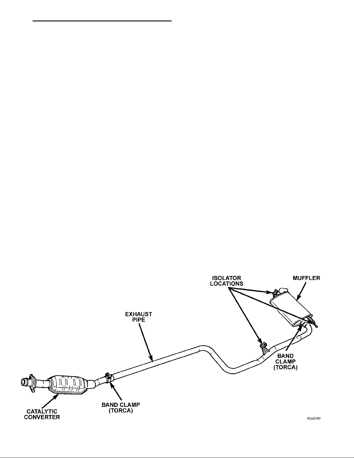
CATALYTIC CONVERTERBAND CLAMP (TORCA)EXHAUST PIPEISOLATOR LOCATIONSMUFFLERBAND CLAMP (TORCA)
PL EXHAUST SYSTEM AND INTAKE MANIFOLD 11 - 1
EXHAUST SYSTEM AND INTAKE MANIFOLD
CONTENTS
page page
GENERAL INFORMATION
CATALYTIC CONVERTER ................. 1
EXHAUST BALL JOINT COUPLING .......... 1
EXHAUST GAS RECIRCULATION (EGR)
SYSTEM ............................. 2
EXHAUST SYSTEMS ..................... 1
HEAT SHIELDS ......................... 2
DESCRIPTION AND OPERATION
EXHAUST MANIFOLD .................... 3
INTAKE MANIFOLD DOHC ................. 3
INTAKE MANIFOLD SOHC ................. 3
DIAGNOSIS AND TESTING
EXHAUST SYSTEM DIAGNOSIS ............ 3
GENERAL INFORMATION
EXHAUST SYSTEMS
The exhaust system has an underfloor catalytic
converter, tail pipe, and muffler (Fig. 1).
EXHAUST BALL JOINT COUPLING
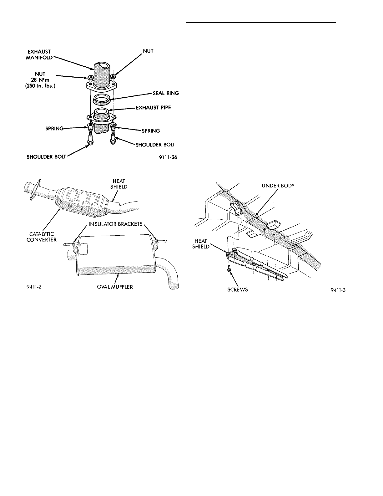
An exhaust ball joint coupling (Fig. 2) is used to
secure the exhaust pipe to the engine exhaust manifold. This flexible joint moves back and forth as the
engine moves, preventing breakage that could occur
REMOVAL AND INSTALLATION
EXHAUST MANIFOLD ................... 10
EXHAUST PIPE AND MUFFLER ............. 4
INTAKE MANIFOLD—DUAL OVERHEAD CAM
ENGINE (DOHC) ....................... 7
INTAKE MANIFOLD—SINGLE OVERHEAD CAM
ENGINE (SOHC) ....................... 5
CLEANING AND INSPECTION
EXHAUST MANIFOLD ................... 11
INTAKE MANIFOLD DOHC ................ 10
INTAKE MANIFOLD SOHC ................ 10
SPECIFICATIONS
TORQUE CHART ....................... 11
from the back-and-forth motion of a transverse
mounted engine.
The exhaust ball joint consists of two bolts, two
springs, and a ball joint seal ring, which is a separate part from the exhaust pipe.
CATALYTIC CONVERTER
There is no regularly scheduled maintenance on
any Chrysler catalytic converter (Fig. 3). If damaged,
the converter must be replaced.
Fig. 1 Exhaust System
Page 2
EXHAUST MANI-FOLD NUTSEAL RINGEXHAUSTPIPESPRINGSHOULDERBOLTSHOULDERBOLTSPRINGNUT 28 N·m(250 in. lbs.)
HEAT SHIELDINSULATOR BRACKETSOVAL MUFFLERCATALYTIC CON-VERTER
UNDER BODYHEATSHIELD SCREWS
11 - 2 EXHAUST SYSTEM AND INTAKE MANIFOLD PL
GENERAL INFORMATION (Continued)
result in excessive exhaust system/floor pan temperatures because of no air movement under the vehicle.
HEAT SHIELDS
The heat shield (Fig. 4) is needed to protect both
the car and the environment from the high temperatures developed in the vicinity of the catalytic converter.
Refer to Group 23, Body and Sheet Metal for service procedures.
CAUTION: Avoid application of rust prevention
compounds or undercoating materials to exhaust
system floor pan heat shield on cars if equipped.
Light over-spray near the edges is permitted. Application of coating will greatly reduce the efficiency
Fig. 2 Ball Joint Connection
of the heat shields resulting in excessive floor pan
temperatures and objectionable fumes.
Fig. 3 Exhaust System Components
CAUTION: Due to exterior physical similarities of
some catalytic converters with pipe assemblies,
extreme care should be taken with replacement
parts.
The combustion reaction caused by the catalyst
releases additional heat in the exhaust system. Causing temperature increases in the area of the reactor
under severe operating conditions. Such conditions
can exist when the engine misfires or otherwise does
not operate at peak efficiency. Do not remove spark
plug wires from plugs or by any other means short
out cylinders if exhaust system is equipped with a
catalytic converter. Failure of the catalytic converter
can occur due to temperature increases caused by
unburned fuel passing through the converter.
The use of the catalysts also involves some non-automotive problems. Unleaded gasoline must be used
to avoid poisoning the catalyst core. Do not allow
engine to operate above 1200 RPM in neutral for
extended periods over 5 minutes. This condition may
Fig. 4 Heat Shield Installation
EXHAUST GAS RECIRCULATION (EGR) SYSTEM
To assist in the control of oxides of nitrogen (NOx)
in engine exhaust, some engines are equipped with
an exhaust gas recirculation system. The use of
exhaust gas to dilute incoming air/fuel mixtures lowers peak flame temperatures during combustion, thus
limiting the formation of NOx.
Exhaust gases are taken from the number four
exhaust port through a hole in the end of the cylinder head. REFER TO GROUP 25, EMISSION SYSTEMS FOR A COMPLETE DESCRIPTION,
DIAGNOSIS AND SERVICE PROCEDURES ON
THE EXHAUST GAS RECIRCULATION SYSTEM
AND COMPONENTS.
Page 3

PL EXHAUST SYSTEM AND INTAKE MANIFOLD 11 - 3
DESCRIPTION AND OPERATION
This long branch fan design enhances low and
midrange torque.
INTAKE MANIFOLD SOHC
The intake manifold is a molded plastic composition, attached to the cylinder head with ten fasteners. This long branch design enhances low and
midrange torque. If removing the intake manifold for
any reason, the fasteners can not be reused.
EXHAUST MANIFOLD
The exhaust manifold is made of nodular cast iron
for strength and high temperatures. Exhaust gasses
exit through a machined, articulated joint connection
to the exhaust pipe.
INTAKE MANIFOLD DOHC
The intake manifold is a two piece aluminum cast-
ing, attached to the cylinder head with ten fasteners.
DIAGNOSIS AND TESTING
EXHAUST SYSTEM DIAGNOSIS
Condition Possible Cause Correction
EXCESSIVE EXHAUST
NOISE
(UNDER HOOD) (b) Manifold to cylinder head leak (b) Tighten manifold and/or replace
EXCESSIVE EXHAUST
NOISE
(a) Exhaust manifold cracked or broken (a) Replace manifold
gasket
(c) EGR Valve Leakage (c)
a, EGR Valve to Manifold Gasket a, Tighten nuts or replace gasket
b, EGR Valve to EGR Tube Gasket b, Tighten nuts or replace gasket
c, EGR Tube to Manifold Tube Nut c, Tighten tube nut
(d) Exhaust Flex Joint (d)
a, Spring height, installed not correct a, Check spring height, both sides
(specification is 32.5 mm, 1.28 inch)
look for source of spring height
variation if out of specification.
b, Exhaust sealing ring defective b, Inspect seal for damage on
round spherical surface. If no
damage is evident, check for exhaust
obstruction causing high back
pressure on heavy acceleration.
(e) Pipe and shell noise from front
exhaust pipe
(a) Leaks at pipe joints (a) Tighten clamps at leaking joints
(b) Burned or blown or rusted out muffler,
tailpipe of exhaust pipe.
(c) Restriction in muffler or tailpipe (c) Remove restriction, if possible or
(d) Converter material in muffler (d) Replace muffler and converter
(e) Characteristic of single wall pipes.
(b) Replace muffler or muffler tailpipe
or exhaust pipe.
replace as necessary.
assemblies. Check fuel injection and
ignition systems for proper operation.
Page 4
11 - 4 EXHAUST SYSTEM AND INTAKE MANIFOLD PL
REMOVAL AND INSTALLATION
EXHAUST PIPE AND MUFFLER
REMOVAL
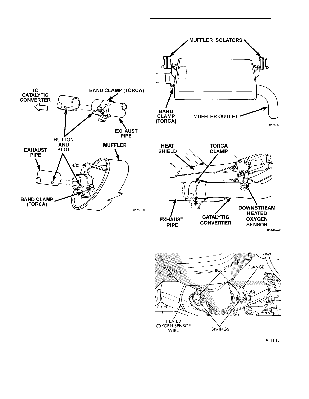
(1) Raise vehicle on hoist and apply penetrating oil
to band clamp fastener of component being removed
(Fig. 5).
Fig. 5 Slip Joint Connection
NOTE: Do not use petroleum-based lubricants
when removing/installing muffler or exhaust pipe
isolators as it may compromise the life of the part.
A suitable substitute is a mixture of liquid dish
soap and water.
HEATSHIELD TORCA CLAMPEXHAUST PIPE CATALYTIC CON-VERTER DOWNSTREAM HEATEDOXYGEN SENSOR
BOLTS FLANGEHEATED OXY-GEN SENSORWIRE SPRINGS
Fig. 6 Exhaust Pipe and Muffler Support Insulators
Fig. 7 Catalytic Converter to Exhaust Pipe
Connection
(2) Loosen band clamp and remove support insulators at muffler (Fig. 6). Remove muffler from exhaust
pipe.
(3) Disconnect downstream heated oxygen sensor
from the catalytic converter pipe.
(4) Remove clamp at the catalytic converter to
exhaust pipe slip joint (Fig. 7). Separate at slip joint.
(5) When removing exhaust pipe, raise rear of
vehicle to relieve body weight from rear suspension
to provide clearance between pipe and lateral arms.
(6) Remove catalytic converter to exhaust manifold
attaching bolts (Fig. 8).
(7) Clean ends of pipes and/or muffler to assure
mating of all parts. Discard broken or worn insulators, rusted clamps, supports and attaching parts.
NOTE: When replacement is required on any component of the exhaust system, you must use original equipment parts (or their equivalent).
Fig. 8 Catalytic Converter to Exhaust Manifold
Connection
Page 5
FUEL RAIL
37 mm (1.45 in.) TOEBOARD FLOOR PANELCROSS MEMBERCONVERTER MOUNTEDHEAT SHIELDCATALYTIC CON-VERTERUNDER BODY HEATSHIELD 23 mm (.91 in.)EXHAUST PIPE
CLAMP SIZETORQUE SPECI-FICATION
PL EXHAUST SYSTEM AND INTAKE MANIFOLD 11 - 5
REMOVAL AND INSTALLATION (Continued)
INSTALLATION
When assembling exhaust system do not tighten
clamps until components are aligned and clearances
are checked.
(1) Assemble catalytic convertor to exhaust manifold ball joint connection (Fig. 8).
(2) Assemble exhaust pipe to catalytic convertor
and the support to the underbody
(3) Install the muffler to exhaust pipe and the supports to the underbody.
(4) Working from the front of system;
(5) Align and tighten the catalytic convertor to
exhaust manifold ball joint bolts (Fig. 8).
(6) Align each component to maintain position and
proper clearance with underbody parts and tighten
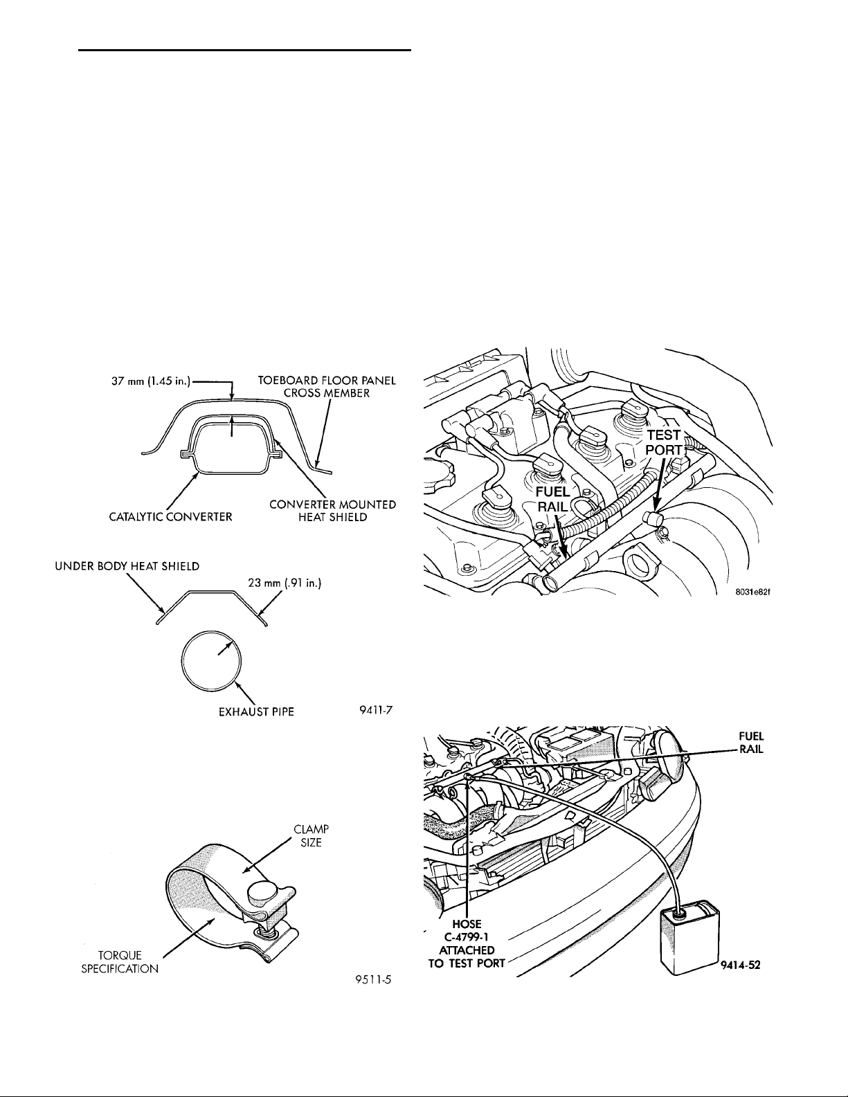
clamps to specifications (Fig. 9).
INTAKE MANIFOLD—SINGLE OVERHEAD CAM ENGINE (SOHC)
REMOVAL
WARNING: RELEASE FUEL SYSTEM PRESSURE
BEFORE SERVICING FUEL SYSTEM COMPONENTS.
SERVICE VEHICLES IN WELL VENTILATED AREAS
AND AVOID IGNITION SOURCES. NEVER SMOKE
WHILE SERVICING THE VEHICLE.
(1) Disconnect negative cable from battery.
(2) Remove fuel filler cap.
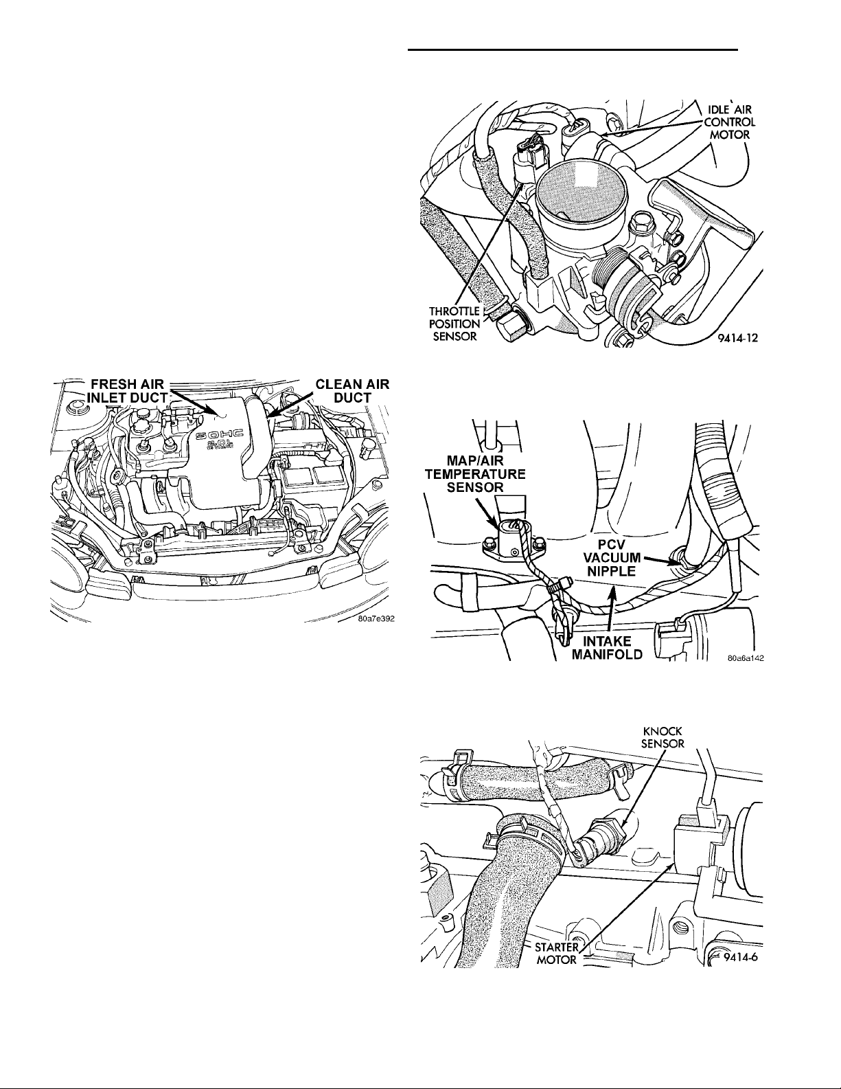
(3) Remove the fresh air duct (Fig. 13).
(4) Remove the protective cap from the fuel pres-
sure test port on the fuel rail (Fig. 11).
Fig. 9 Exhaust Clearance
(7) Connect the downstream heated oxygen sensor.
(8) A new style band clamp (Torca) will be used on
the PL exhaust system (Fig. 10).
Fig. 11 Fuel Pressure Test Port
(5) Place the open end of fuel pressure release
hose, tool number C-4799-1, into an approved gaso-
FUEL RAILHOSEC-4799-1ATTACHEDTO TESTPORT
line container. Connect the other end of hose to the
fuel pressure test port (Fig. 12). Fuel pressure will
bleed off through the hose into the gasoline container. Fuel gauge C-4799-A contains hose C-4799-1.
Fig. 10 Band Clamp (Torca)
Fig. 12 Releasing Fuel Pressure
Page 6
THROTTLEPOSITIONSENSOR
MAP/AIR TEMPERATURESENSORPCV VACUUM NIPPLEINTAKE MANIFOLD
KNOCK SEN-SORSTARTERMOTOR
IDLE AIR CON-
TROL MOTOR
11 - 6 EXHAUST SYSTEM AND INTAKE MANIFOLD PL
REMOVAL AND INSTALLATION (Continued)
(6) Perform fuel system pressure release procedure
before attempting any repairs.
(7) Disconnect the fuel supply line quick connect at
the fuel tube assembly.
WARNING: WRAP SHOP TOWELS AROUND HOSE
TO CATCH ANY GASOLINE SPILLAGE.
(8) Remove fuel rail assembly attaching screws
and remove fuel rail assembly from engine. Cover
injector holes with suitable covering.
CAUTION: Do not set fuel injectors on their tips,
damage may occur to the injectors
(9) Remove clean air duct and upper air filter
housing (Fig. 13).
Fig. 14 Idle Air Control (IAC) Motor and Throttle
Position Sensor (TPS) Wiring Connectors and
Vacuum Hose Connection
Fig. 13 Clean Air Duct to Throttle Body Assembly
(10) Remove accelerator, kickdown and speed control cables from throttle lever and bracket. Refer to
Group 14, Fuel System Throttle Body Removal for
procedures.
(11) Disconnect Idle Air Control (IAC) motor and
Throttle Position Sensor (TPS) wiring connectors
(Fig. 14).
(12) Disconnect vacuum hoses from throttle body
(Fig. 14).
(13) Disconnect Manifold Absolute Pressure/Intake
Air Temperature Sensor (TMAP), electrical connector
(Fig. 15). Disconnect vapor and brake booster hoses.
(14) Disconnect knock sensor electrical connector
(Fig. 16) and disconnect wiring harness from tab
located on the intake manifold.
(15) Disconnect wiring at starter.
(16) Remove transmission to throttle body support
bracket fasteners at the throttle body and loosen the
fastener at the transmission end.
(17) Remove throttle body.
Fig. 15 Intake Manifold Electrical and Vacuum Hose
Connections
Fig. 16 Knock Sensor
Page 7
EGR TUBE TO INTAKEMANIFOLD FASTENERS EGR VALVE TOTUBE FASTENERS
INTAKE MANIFOLD TOWATER INLET SUPPORT
PL EXHAUST SYSTEM AND INTAKE MANIFOLD 11 - 7
REMOVAL AND INSTALLATION (Continued)
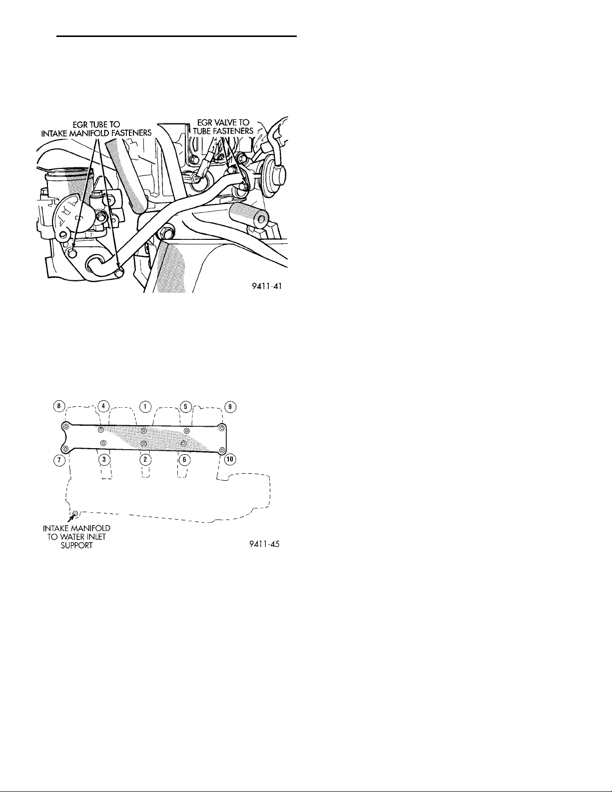
(18) Remove EGR tube bolts at the valve and at
the intake manifold (Fig. 17). Remove tube from
engine.
Fig. 17 EGR Tube Assembly
(19) Remove the intake manifold to inlet water
tube support fastener (Fig. 18).
(20) Remove 10 intake manifold screw and washer.
Discard the fasteners. Remove intake manifold.
(4) Connect PCV and brake booster hoses.
(5) Inspect quick connect fittings for damage,
replace if necessary Refer to Group 14, Fuel System
for procedure. Lube tube with clean 30w engine oil,
Connect fuel supply hose to fuel rail assembly. Check
connection by pulling on connector to insure it locked
into position.
(6) Install throttle body. Tighten fastener to 22
N·m (200 in. lbs.). Install transmission to throttle
body support bracket and tighten to 11.9 N·m (105
in. lbs.) at the throttle body first. Next tighten the
bracket at the transmission.
(7) Connect Manifold Absolute Pressure/Intake Air
Temperature Sensor (TMAP) wiring connector.
(8) Connect knock sensor connector, and wiring at
starter. Connect wiring harness to intake manifold
tab.
(9) Connect Idle Air Control (IAC) motor and
Throttle Position Sensor (TPS) wiring connectors.
(10) Connect vacuum hoses to throttle body.
(11) Install accelerator, kickdown and speed control cables to their bracket and connect them to the
throttle lever. Refer to Group 14, Fuel System Throttle Body Installation for procedure.
(12) Loose assemble the EGR tube onto valve and
intake manifold finger tight. Tighten tube fasteners
at the EGR valve first to 11 N·m (95 in. lbs.) then,
tighten the intake manifold side fasteners to 11 N·m
(95 in. lbs.).
(13) Install clean air duct to air filter housing.
Tighten clamp to 3 N·m (30 in. lbs.).
(14) Connect negative battery cable.
(15) Install fresh air duct to air cleaner and
tighten wing nut.
(16) With the DRB scan tool use ASD Fuel System
Test to pressurize system to check for leaks.
Fig. 18 Intake Manifold Tightening Sequence
INSTALLATION
Before installing manifold. Clean all mating surfaces. Replace all seals, with new seals. All intake
manifold fasteners and washers are to be discarded
and NEW fasteners and washers are to be used.
(1) Install intake manifold onto cylinder head and
tighten fasteners to 12 N·m (105 in. lbs.) in sequence
shown in (Fig. 18).
(2) Install intake manifold to water inlet support
fastener (Fig. 18) tighten to 12 N·m (105 in. lbs.).
(3) Remove covering from fuel injector holes and
insure the holes are clean. Install fuel rail assembly
to intake manifold. Tighten screws to 23 N·m (200 in.
lbs.).
CAUTION: When using the ASD Fuel System Test,
the Auto Shutdown (ASD) relay will remain energized for 7 minutes or until the ignition switch is
turned to the OFF position, or Stop All Test is
selected.
INTAKE MANIFOLD—DUAL OVERHEAD CAM ENGINE (DOHC)
REMOVAL
WARNING: RELEASE FUEL SYSTEM PRESSURE
BEFORE SERVICING FUEL SYSTEM COMPONENTS.
SERVICE VEHICLES IN WELL VENTILATED AREAS
AND AVOID IGNITION SOURCES. NEVER SMOKE
WHILE SERVICING THE VEHICLE.
(1) Disconnect negative cable from battery.
(2) Remove fuel filler cap.
Page 8
11 - 8 EXHAUST SYSTEM AND INTAKE MANIFOLD PL
REMOVAL AND INSTALLATION (Continued)
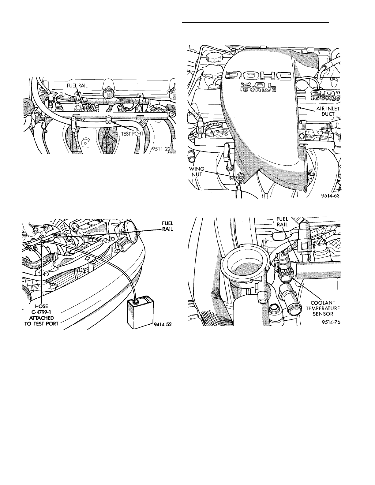
(3) Remove fresh air inlet duct (Fig. 21). Remove
wing nut on intake.
(4) Remove the protective cap from the fuel pressure test port on the fuel rail (Fig. 19).
Fig. 19 Fuel Pressure Test Port
(5) Place the open end of fuel pressure release
hose, tool number C- 4799-1, into an approved gaso-
FUEL RAILHOSEC-4799-1ATTACHEDTO TESTPORT
line container. Connect the other end of hose to the
fuel pressure test port (Fig. 20). Fuel pressure will
bleed off through the hose into the gasoline container. Fuel gauge C-4799-A contains hose C-4799-1.
FUEL RAIL
Fig. 21 Fresh Air Inlet Duct
COOLANT TEMPER-ATURE SENSOR
Fig. 20 Releasing Fuel Pressure—Typical
(6) Disconnect the fuel supply line-connect at the
fuel tube assembly.
(7) Remove clean air inlet duct.
WARNING: WRAP SHOP TOWELS AROUND HOSE
TO CATCH ANY GASOLINE SPILLAGE.
(8) Disconnect the coolant temperature sensor
(Fig. 22).
(9) Remove fuel rail assembly attaching screws
and remove fuel rail assembly from engine. Cover
injector holes with suitable covering.
CAUTION: Do not set fuel injectors on their tips,
damage may occur to the injectors
Fig. 22 Engine Coolant Temperature Sensor
(10) Remove accelerator, kickdown and speed control cables from throttle lever and bracket. Refer to
Group 14, Fuel System Throttle Body Removal for
procedures.
(11) Remove throttle body.
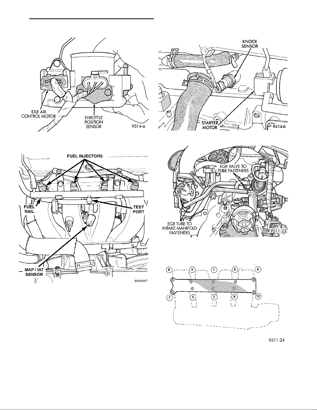
(12) Disconnect Idle Air Control (IAC) motor and
Throttle Position Sensor (TPS) wiring connectors
(Fig. 23).
(13) Disconnect vacuum hoses from throttle body.
(14) Disconnect Manifold Absolute Pressure/Intake Air Temperature sensor (TMAP) electrical connector. Disconnect vapor and brake booster hoses
(Fig. 24).
(15) Disconnect knock sensor electrical connector
and disconnect wiring harness from tab located on
the intake manifold (Fig. 25).
Page 9
PL EXHAUST SYSTEM AND INTAKE MANIFOLD 11 - 9
REMOVAL AND INSTALLATION (Continued)
EGR VALVE TOTUBE FASTENERSEGR TUBE TOINTAKE MANI-FOLD FASTEN-ERS
FUEL INJECTORSFUEL RAILTEST PORTMAP/IAT SENSOR
Fig. 23 Idle Air Control (IAC) Motor and Throttle
Position Sensor (TPS) Wiring Connectors
Fig. 25 Knock Sensor Electrical
Fig. 26 EGR Tube Assembly
Fig. 24 Manifold Absolute Pressure/Intake Air
Temperature Sensor (TMAP) Electrical Connector
(16) Disconnect wiring from starter.
(17) Remove EGR tube bolts at the valve and at
the intake manifold (Fig. 26). Remove tube from
engine.
(18) Remove intake manifold fastener. Remove
intake manifold.
INSTALLATION
Before installing manifold. Clean all mating surfaces. Replace all gaskets, with new.
(1) Install intake manifold onto cylinder head and
tighten fasteners to 28 N·m (250 in. lbs.) in sequence
shown in (Fig. 27).
Fig. 27 Intake Manifold Tightening Sequence
(2) Remove covering from fuel injector holes and
insure the holes are clean. Install fuel rail assembly
to intake manifold. Tighten screws to 23 N·m (200 in.
lbs.).
(3) Connect PCV and brake booster hoses.
Page 10
11 - 10 EXHAUST SYSTEM AND INTAKE MANIFOLD PL
REMOVAL AND INSTALLATION (Continued)
(4) Inspect quick connect fittings for damage,
replace if necessary Refer to Group 14, Fuel System
for procedure. Lube tube with clean 30w engine oil,
Connect fuel supply hose to fuel rail assembly. Check
connection by pulling on connector to insure it locked
into position.
(5) Install throttle body. Tighten fastener to 22
N·m (200 in. lbs.).
(6) Connect Manifold Absolute Pressure/Intake Air
Temperature Sensor (TMAP) wiring connector.
(7) Connect knock sensor connector and starter
wires. Connect wiring harness to intake manifold
tab.
(8) Connect Idle Air Control (IAC) motor and
Throttle Position Sensor (TPS) wiring connectors.
(9) Connect vacuum hoses to throttle body.
(10) Install accelerator, kickdown and speed control cables to their bracket and connect them to the
throttle lever. Refer to Group 14, Fuel System Throttle Body Installation for procedure.
(11) Loose assemble the EGR tube onto valve and
intake manifold finger tight. Tighten tube fasteners
at the EGR valve first to 11 N·m (95 in. lbs.) then,
tighten the intake manifold side fasteners to 11 N·m
(95 in. lbs.).
(12) Install clean air duct.
(13) Install fresh air duct to air filter housing.
Tighten clamp to 3 N·m (25 in. lbs.).
(14) Connect negative battery cable.
(15) With the DRB scan tool use ASD Fuel System
Test to pressurize system to check for leaks.
CAUTION: When using the ASD Fuel System Test,
the Auto Shutdown (ASD) relay will remain energized for 7 minutes or until the ignition switch is
turned to the OFF position, or Stop All Test is
selected.
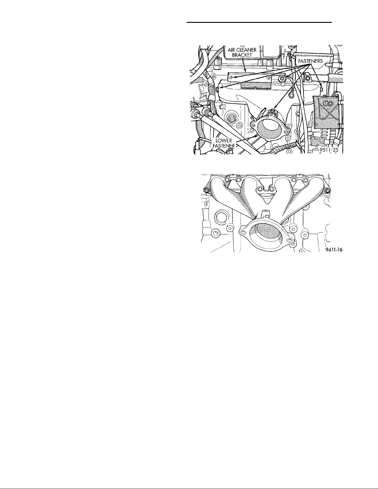
EXHAUST MANIFOLD
tighten to 23 N·m (200 in. lbs.) starting at center and
progressing outward in both directions. Repeat this
procedure until all fasteners are at specified torque.
nector.
N·m (250 in. lbs.)
Fig. 28 Exhaust Manifold Heat Shield
Fig. 29 Exhaust Manifold
(2) Install exhaust manifold heat shield.
(3) Connect upstream heated oxygen sensor con-
(4) Install air cleaner bracket and assembly.
(5) Attach exhaust pipe and tighten fasteners to 28
REMOVAL
(1) Remove air cleaner assembly and bracket.
(2) Remove exhaust manifold heat shield (Fig. 28).
(3) Disconnect upstream heated oxygen sensor connector.
(4) Remove exhaust pipe from manifold.
(5) Remove 8 exhaust manifold retaining fasteners
and remove exhaust manifold (Fig. 29).
INSTALLATION
NOTE: Discard gasket and clean all gasket surfaces of manifolds and cylinder head.
(1) Set exhaust manifold and gasket in place.
Apply Loctite 271 or equivalent to fasteners and
CLEANING AND INSPECTION
INTAKE MANIFOLD SOHC
INSPECT AND CLEAN
Check for:
• Inspect manifold for cracks or distortions.
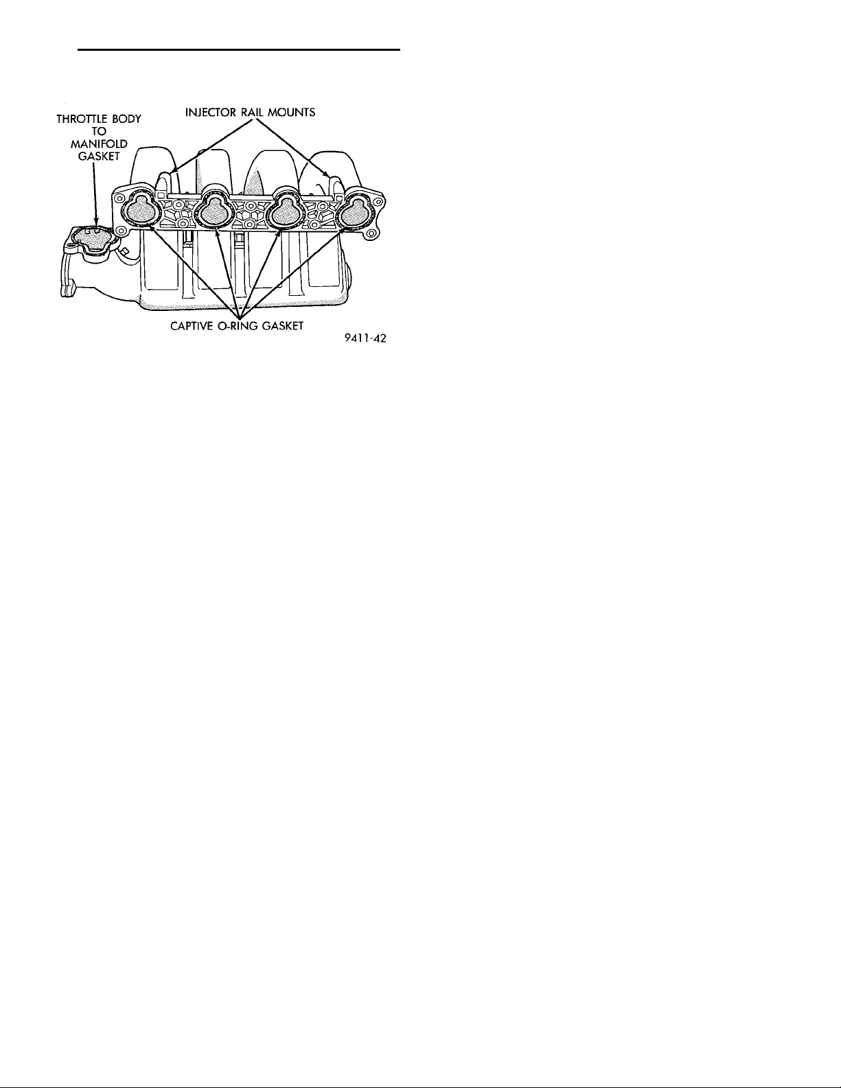
• Check for torn or missing O-rings at the mating
surface of the manifold (Fig. 30).
INTAKE MANIFOLD DOHC
INSPECT AND CLEAN
Check for:
• Inspect manifold for cracks or distortions.
Page 11
THROTTLE BODYTO MANIFOLDGASKET INJECTOR RAIL MOUNTSCAPTIVE O-RING GASKET
PL EXHAUST SYSTEM AND INTAKE MANIFOLD 11 - 11
CLEANING AND INSPECTION (Continued)
(3) Inspect manifolds for cracks or distortion.
Replace manifold if necessary.
SPECIFICATIONS
TORQUE CHART
EGR Tube Attaching
Bolts ....................11N·m(95in.lbs.)
Exhaust Manifold to Exhaust Pipe
Nuts ....................27N·m(20ft.lbs.)
Exhaust Manifold Mounting
Bolts ...................23N·m(200 in. lbs.)
Intake Manifold Mounting
Bolts SOHC .............12N·m(105 in. lbs.)
Fig. 30 Intake Manifold O-Rings
• Check for torn gasket at the mating surface of
the manifold.
EXHAUST MANIFOLD
CLEAN AND INSPECT
(1) Discard gasket and clean all gasket surfaces of
manifolds and cylinder head.
(2) Test manifold gasket surfaces for flatness with
straight edge. Surface must be flat within 0.15 mm
per 300 mm (.006 in. per foot) of manifold length.
Bolts DOHC .............28N·m(250 in. lbs.)
Heat Shield Mounting (Body)
Bolts .....................4N·m(35in.lbs.)
Exhaust System Band Clamps (Torca)
Fastener .................75N·m(55ft.lbs.)
Exhaust Manifold Heat Shield
Bolts ...................23N·m(200 in. lbs.)
Page 12

 Loading...