

Page 1
ENGINE OILAUTOMATICTRANSMISSIONFLUIDENGINE COOLANT BRAKE FLUIDPOWER STEERINGFLUIDWINDSHIELDWASHER FLUID
PL LUBRICATION AND MAINTENANCE 0 - 1
LUBRICATION AND MAINTENANCE
CONTENTS
page page
GENERAL INFORMATION .................. 1
JUMP STARTING, TOWING AND HOISTING ... 7
GENERAL INFORMATION
INDEX
page page
GENERAL INFORMATION
CLASSIFICATION OF LUBRICANTS .......... 1
FLUID CAPACITIES ...................... 2
INTERNATIONAL SYMBOLS ............... 1
GENERAL INFORMATION
INTRODUCTION
Service and maintenance procedures for components and systems listed in Schedule—A or B can be
found by using the Group Tab Locator index at the
front of this manual. If it is not clear which group
contains the information needed, refer to the index at
the back of this manual.
There are two maintenance schedules that show
proper service based on the conditions that the vehicle is subjected to.
Schedule— A , lists scheduled maintenance to be
performed when the vehicle is used for general transportation.
Schedule— B , lists maintenance intervals for vehicles that are operated under the conditions listed at
the beginning of the Maintenance Schedule section.
Use the schedule that best describes your driving
conditions.
Where time and mileage are listed, follow the
interval that occurs first.
MAINTENANCE SCHEDULES ............... 3
INTRODUCTION ........................ 1
PARTS AND LUBRICANT
RECOMMENDATIONS .................. 1
INTERNATIONAL SYMBOLS
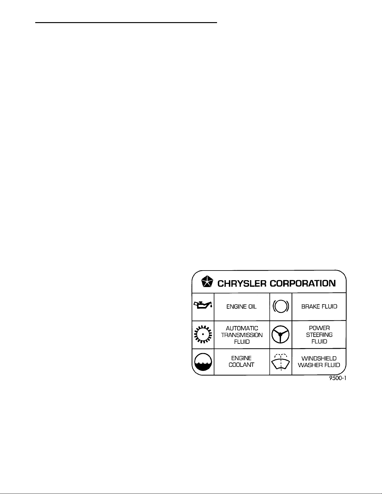
Chrysler Corporation uses international symbols to
identify engine compartment lubricant and fluid
inspection and fill locations (Fig. 1).
Fig. 1 International Symbols
PARTS AND LUBRICANT RECOMMENDATIONS
When service is required, Chrysler Corporation
recommends that only Mopart brand parts, lubricants and chemicals be used. Mopar provides the
best engineered products for servicing Chrysler Corporation vehicles.
Page 2
0 - 2 LUBRICATION AND MAINTENANCE PL
GENERAL INFORMATION (Continued)
CLASSIFICATION OF LUBRICANTS
Only lubricants that are endorsed by the following
organization should be used to service a Chrysler
Corporation vehicle.
• Society of Automotive Engineers (SAE)
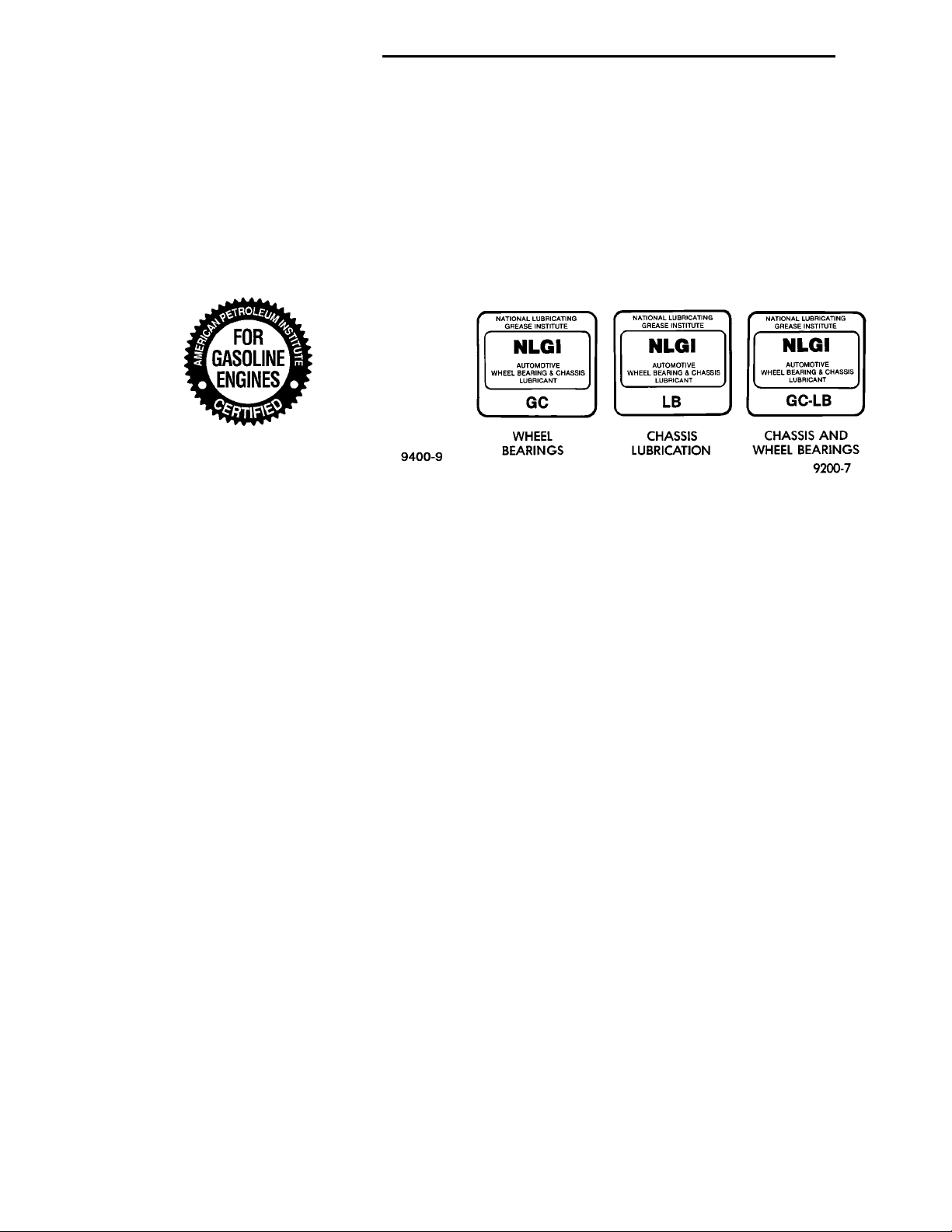
• American Petroleum Institute (API) (Fig. 2)
• National Lubricating Grease Institute (NLGI)
(Fig. 3)
Fig. 2 API Symbol
ENGINE OIL
SAE GRADE RATING INDICATES ENGINE OIL VISCOSITY
An SAE viscosity grade is used to specify the viscosity of engine oil. SAE 30 specifies a single viscosity engine oil. Engine oils also have multiple
viscosities. These are specified with a dual SAE viscosity grade which indicates the cold-to-hot temperature viscosity range.
• SAE 30 = single grade engine oil.
• SAE 10W-30 = multiple grade engine oil.
API QUALITY CLASSIFICATION
The API Service Grade specifies the type of performance the engine oil is intended to provide. The API
Service Grade specifications also apply to energy conserving engine oils.
Use engine oils that are API Service Certified.
5W-30 and 10W-30 MOPAR engine oils conform to
specifications.
Refer to Group 9, Engine for engine oil specification.
GEAR LUBRICANTS
SAE ratings also apply to multiple grade gear
lubricants. In addition, API classification defines the
lubricants usage.
LUBRICANTS AND GREASES
Lubricating grease is rated for quality and usage
WHEELBEARINGS CHASSIS LUBRICA-TION CHASSIS ANDWHEEL BEARINGS
by the NLGI. All approved products have the NLGI
symbol (Fig. 3) on the label. At the bottom NLGI
symbol is the usage and quality identification letters.
Wheel bearing lubricant is identified by the letter
“G”. Chassis lubricant is identified by the latter “L”.
The letter following the usage letter indicates the
quality of the lubricant. The following symbols indicate the highest quality.
Fig. 3 NLGI Symbol
FLUID CAPACITIES
FUEL TANK
All .........................47.3 L (12.5 gal.)
ENGINE OIL W/FILTER CHANGE
All ..........................4.25 L (4.5 qts.)
ENGINE OIL W/OUT FILTER CHANGE
All ...........................3.8L(4.0 qts.)
COOLING SYSTEM
All* ...........................6L(6.5 qts.)
*Includes heater and coolant recovery bottle
AUTOMATIC TRANSAXLE
NOTE: Overhaul Fill Capacity with Torque Converter Empty
31TH ........................8.4L(8.9 qts.)
31 TH (Fleet Vehicles) ............8.7L(9.2 qts.)
MANUAL TRANSAXLE
NV T350 ................1.9-2.2 L (4.0-4.6 pts.)
POWER STEERING
All ..........................0.95 L (2.0 pts.)
Page 3

PL LUBRICATION AND MAINTENANCE 0 - 3
MAINTENANCE SCHEDULES
INDEX
page page
GENERAL INFORMATION
INTRODUCTION ........................ 3
SCHEDULE—A ......................... 3
GENERAL INFORMATION
INTRODUCTION
Service and maintenance procedures for components and systems listed in Schedule—A or B can be
found by using the Group Tab Locator index at the
front of this manual. If it is not clear which group
contains the information needed, refer to the index at
the back of this manual.
There are two maintenance schedules that show
proper service based on the conditions that the vehicle is subjected to. Use the schedule that best
describes these conditions.
Schedule— A , lists maintenance recommended for
vehicles used for general transportation.
Schedule— B , lists maintenance recommended for
vehicles used under the following conditions:
• Frequent short trip driving less than 5 miles (8
km)
• Frequent driving in dusty conditions
• Frequent trailer towing
• Extensive idling
• More than 50% of your driving is at sustained
high speeds during hot weather, above 90°F (32°C)
Where time and mileage are listed, follow the
interval that occurs first.
SCHEDULE—B ......................... 4
UNSCHEDULED INSPECTION .............. 3
Once A Month
• Check tire pressure and look for unusual wear
or damage.
• Inspect battery, clean, and tighten terminals as
required.
• Check fluid levels of coolant reservoir, power
steering and automatic transmission and add as
required.
• Check all lights and all other electrical items for
correct operation.
At Each Oil Change
• Inspect exhaust system.
• Inspect brake hoses.
• Inspect the CV joints and front suspension com-
ponents.
• Rotate the tires at each oil change interval
shown on Schedule—A (7,500 miles) or every other
interval shown on schedule—B (6,000 miles).
• Check coolant level, hoses and clamps.
• Check the manual transaxle fluid level.
• If the mileage is less than 7,500 miles (12 000
km) yearly, replace the engine oil filter at each oil
change.
SCHEDULE—A
EMISSION CONTROL SYSTEM MAINTENANCE
The scheduled emission maintenance listed in bold
type on the Maintenance Schedules, must be done at
the mileage specified to assure the continued proper
functioning of the emission control system. These,
and all other maintenance services included in this
manual, should be done to provide the best vehicle
performance and reliability. More frequent maintenance may be needed for vehicles in severe operating
conditions such as dusty areas and very short trip
driving.
UNSCHEDULED INSPECTION
At Each Stop For Fuel
• Check engine oil level, add as required.
• Check windshield washer solvent and add if
required.
7,500 Miles (12 000 km) or at 6 months
• Change engine oil.
15,000 Miles (24 000 km) or at 12 months
• Change engine oil.
• Replace engine oil filter.
• Adjust drive belt tension.
22,500 Miles (36 000 km) or at 18 months
• Change engine oil.
• Inspect the front brake pads and rear brake lin-
ings.
30,000 Miles (48 000 km) or at 24 months
• Change engine oil.
• Replace engine oil filter.
• Lubricate front suspension ball joints.
• Adjust drive belt tension.
Page 4

0 - 4 LUBRICATION AND MAINTENANCE PL
GENERAL INFORMATION (Continued)
• Replace air cleaner element.
• Replace spark plugs.
37,500 Miles (60 000 km) or at 30 months
• Change engine oil.
45,000 Miles (72 000 km) or at 36 months
• Change engine oil.
• Replace engine oil filter.
• Inspect front brake pads and rear brake linings.
• Adjust drive belt tension.
• Flush and replace engine coolant at 36 months,
regardless of mileage.
52,500 Miles (84 000 km) or at 42 months
• Change engine oil.
• Flush and replace engine coolant if not done at
36 months.
60,000 Miles (96 000 km) or at 48 months
• Change engine oil.
• Replace engine oil filter.
• Check and replace, if necessary***, the
PCV valve.**
• Lubricate front suspension upper ball joints.
• Replace drive belts.
• Replace air cleaner element.
• Replace ignition cables.
• Replace spark plugs.
67,500 Miles (108 000 km) or at 54 months
• Change engine oil.
• Inspect front brake pads and rear brake linings.
75,000 Miles (120 000 km) or at 60 months
• Change engine oil.
• Replace engine oil filter.
• Adjust drive belt tension.
• Flush and replace engine coolant if it has been
30,000 miles (48 000 km) or 24 months since last
change.
82,500 Miles (132 000 km) or at 66 months
• Change engine oil.
• Flush and replace engine coolant if it has been
30,000 miles (48 000 km) or 24 months since last
change.
• Replace spark plugs.
97,500 Miles (156 000 km) or at 78 months
• Change engine oil.
105,000 Miles (168 000 km)
• Change engine oil.
• Replace engine oil filter.
• Replace engine timing belt
• Adjust drive belt tension.
SCHEDULE—B
3,000 Miles (5 000 km)
• Change engine oil
6,000 Miles (10 000 km)
• Change engine oil
• Replace engine oil filter.
9,000 Miles (14 000 km)
• Change engine oil
• Inspect front brake pads and rear brake lining.
12,000 Miles (19 000 km)
• Change engine oil
• Replace engine oil filter.
15,000 Miles (24 000 km)
• Change engine oil
• Adjust drive belt tension.
• Inspect and replace, if required, the air
cleaner element.
• Change automatic transaxle fluid and filter.
Adjust the bands.*
18,000 Miles (29 000 km)
• Change engine oil
• Replace engine oil filter.
• Inspect front brake pads and rear brake linings.
21,000 Miles (34 000 km)
• Change engine oil
24,000 Miles (38 000 km)
• Change engine oil
• Replace engine oil filter.
90,000 Miles (144 000 km) or at 72 months
• Change engine oil.
• Replace engine oil filter.
• Check and replace, if necessary***, the
PCV valve.**
• Lubricate front suspension upper ball joints.
• Inspect front brake pads and rear brake linings.
• Adjust drive belt tension.
• Replace air cleaner air cleaner element.
27,000 Miles (43 000 km)
• Change engine oil
• Inspect front brake pads and rear brake linings.
30,000 Miles (48 000 km)
• Change engine oil
• Replace engine oil filter.
• Check and replace, if necessary, the PCV
valve.**
Page 5

PL LUBRICATION AND MAINTENANCE 0 - 5
GENERAL INFORMATION (Continued)
• Lubricate front suspension upper ball joints.
• Adjust drive belt tension.
• Replace air cleaner element.
• Replace spark plugs.
• Change automatic transmission fluid and filter.
Adjust the bands.*
33,000 Miles (53 000 km)
• Change engine oil.
36,000 Miles (58 000 km)
• Change engine oil.
• Replace engine oil filter.
• Flush and replace engine coolant.
• Inspect front brake pads and rear brake linings.
39,000 Miles (62 000 km)
• Change engine oil.
42,000 Miles (67 000 km)
• Change engine oil.
• Replace engine oil filter.
45,000 Miles (72 000 km)
• Change engine oil.
• Inspect front brake pads and rear brake linings.
• Inspect and replace, if necessary, the air
cleaner element.
• Adjust drive belt tension.
• Change automatic transaxle fluid and filter.
Adjust the bands.*
• Replace spark plugs.
• Change automatic transaxle fluid and filter.
Adjust the bands.*
63,000 Miles (101 000 km)
• Change engine oil.
• Inspect front brake pads and rear brake linings.
66,000 Miles (106 000 km)
• Change engine oil.
• Replace engine oil filter.
69,000 Miles (110 000 km)
• Change engine oil.
72,000 Miles (115 000 km)
• Change engine oil.
• Replace engine oil filter.
• Inspect front brake pads and rear brake linings.
75,000 Miles (120 000 km)
• Change engine oil.
• Adjust drive belt tension.
• Inspect and replace, if necessary, the air
cleaner element.
• Change automatic transaxle fluid and filter.
Adjust the bands.*
78,000 Miles (125 000 km)
• Change engine oil.
• Replace engine oil filter.
48,000 Miles (77 000 km)
• Change engine oil.
• Replace engine oil filter.
51,000 Miles (82 000 km)
• Change engine oil.
• Flush and replace engine coolant.
54,000 Miles (86 000 km)
• Change engine oil.
• Replace engine oil filter.
• Inspect front brake pads and rear brake linings.
57,000 Miles (91 000 km)
• Change engine oil.
60,000 Miles (96 000 km)
• Change engine oil.
• Replace engine oil filter.
• Check and replace, if necessary***, the
PCV valve.**
• Lubricate front suspension upper ball joints.
• Replace drive belts.
• Replace air cleaner element.
• Replace ignition cables.
81,000 Miles (130 000 km)
• Change engine oil.
• Flush and replace the engine coolant.
• Inspect front brake pads and rear brake linings.
84,000 Miles (134 000 km)
• Change engine oil.
• Replace engine oil filter.
87,000 Miles (139 000 km)
• Change engine oil.
90,000 Miles (144 000 km)
• Change engine oil.
• Replace engine oil filter.
• Inspect front brake pads and rear brake linings.
• Check and replace, if necessary***, the
PCV valve.**
• Lubricate front suspension upper ball joints.
• Adjust drive belt tension.
• Replace air cleaner element.
• Replace spark plugs.
• Change automatic transaxle fluid and filter.
Adjust the bands.*
Page 6

0 - 6 LUBRICATION AND MAINTENANCE PL
GENERAL INFORMATION (Continued)
93,000 Miles (149 000 km)
• Change engine oil.
96,000 Miles (154 000 km)
• Change engine oil.
• Replace engine oil filter.
99,000 Miles (158 000 km)
• Change engine oil.
• Inspect front brake pads and rear brake linings.
102,000 Miles (163 000km)
• Change engine oil.
• Replace engine oil filter.
105,000 Miles (168 000km)
• Replace the engine timing belt
• Change engine oil.
• Replace engine oil filter.
• Adjust drive belt tension.
• Inspect and replace, if necessary, the air
cleaner element.
*Police, taxi, or delivery service usage and trailer
towing require the more frequent transaxle service
indicated witha*inschedule—B. Perform these services if the vehicle is usually operated under these
conditions.
NOTE: **This maintenance is recommended by
Chrysler to the owner but is not required to maintain the warranty on the PCV valve.
NOTE: ***This maintenance is not required if the
PCV valve was previously replaced.
Page 7
ENGINE GROUNDNEGATIVE JUMPER CABLEBATTERY NEGATIVE CABLEPOSITIVE JUMPER CABLEBATTERY POSITIVE CABLEBATTERYTEST INDICATOR
PL LUBRICATION AND MAINTENANCE 0 - 7
JUMP STARTING, TOWING AND HOISTING
INDEX
page page
SERVICE PROCEDURES
HOISTING RECOMMENDATIONS ........... 9
SERVICE PROCEDURES
JUMP STARTING PROCEDURE
WARNING: REVIEW ALL SAFETY PRECAUTIONS
AND WARNINGS IN GROUP 8A, BATTERY/STARTING/CHARGING SYSTEMS DIAGNOSTICS. DO NOT
JUMP START A FROZEN BATTERY, PERSONAL
INJURY CAN RESULT. DO NOT JUMP START WHEN
MAINTENANCE FREE BATTERY INDICATOR DOT IS
YELLOW OR BRIGHT COLOR. DO NOT JUMP
START A VEHICLE WHEN THE BATTERY FLUID IS
BELOW THE TOP OF LEAD PLATES. DO NOT
ALLOW JUMPER CABLE CLAMPS TO TOUCH
EACH OTHER WHEN CONNECTED TO A BOOSTER
SOURCE. DO NOT USE OPEN FLAME NEAR BATTERY. REMOVE METALLIC JEWELRY WORN ON
HANDS OR WRISTS TO AVOID INJURY BY ACCIDENTAL ARCING OF BATTERY CURRENT. WHEN
USING A HIGH OUTPUT BOOSTING DEVICE, DO
NOT ALLOW BATTERY VOLTAGE TO EXCEED 16
VOLTS. REFER TO INSTRUCTIONS PROVIDED
WITH DEVICE BEING USED.
JUMP STARTING PROCEDURE ............. 7
TOWING RECOMMENDATIONS ............. 8
the automatic transmission in PARK or the manual
transmission in NEUTRAL and turn the ignition
OFF.
(3) On disabled vehicle, place gear selector in park
or neutral and set park brake. Turn off all accessories.
(4) Connect jumper cables to booster battery. RED
clamp to positive terminal (+). BLACK clamp to negative terminal (-). DO NOT allow clamps at opposite
end of cables to touch, electrical arc will result.
Review all warnings in this procedure.
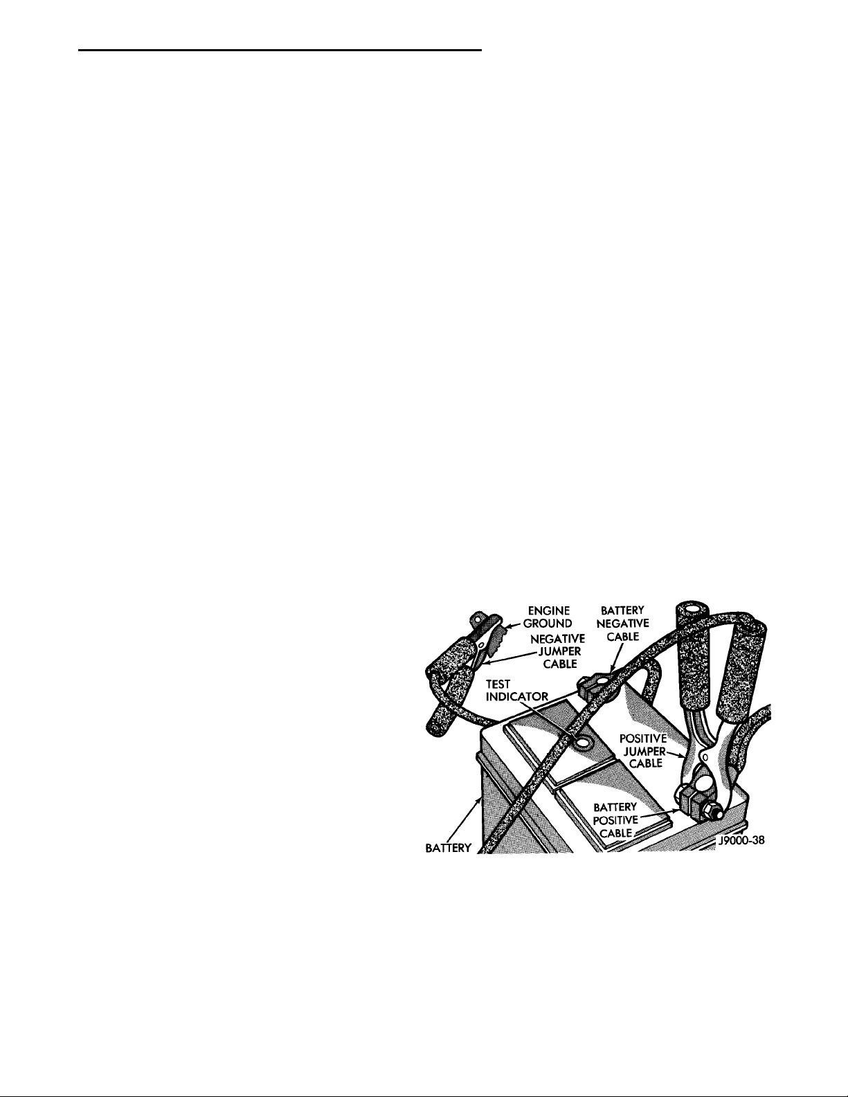
(5) On disabled vehicle, connect RED jumper cable
clamp to positive (+) terminal. Connect BLACK
jumper cable clamp to engine ground as close to the
ground cable attaching point as possible (Fig. 1).
(6) Start the engine in the vehicle which has the
booster battery, let the engine idle a few minutes,
then start the engine in the vehicle with the discharged battery.
CAUTION: When using another vehicle as a
booster, do not allow vehicles to touch. Electrical
systems can be damaged on either vehicle.
TO JUMP START A DISABLED VEHICLE:
(1) Raise hood on disabled vehicle and visually
inspect engine compartment for:
• Battery cable clamp condition, clean if necessary.
• Frozen battery.
• Yellow or bright color test indicator, if equipped.
• Low battery fluid level.
• Generator drive belt condition and tension.
• Fuel fumes or leakage, correct if necessary.
CAUTION: If the cause of starting problem on disabled vehicle is severe, damage to booster vehicle
charging system can result.
(2) When using another vehicle as a booster
source, park the booster vehicle within cable reach.
Turn off all accessories, set the parking brake, place
Fig. 1 Jumper Cable Clamp Connections
CAUTION: Do not crank starter motor on disabled
vehicle for more than 15 seconds, starter will overheat and could fail.
(7) Allow battery in disabled vehicle to charge to
at least 12.4 volts (75% charge) before attempting to
start engine. If engine does not start within 15 seconds, stop cranking engine and allow starter to cool
(15 min.), before cranking again.
Page 8
WHEEL LIFTFLAT BED
0 - 8 LUBRICATION AND MAINTENANCE PL
SERVICE PROCEDURES (Continued)
DISCONNECT CABLE CLAMPS AS FOLLOWS:
• Disconnect BLACK cable clamp from engine
ground on disabled vehicle.
• When using a Booster vehicle, disconnect
BLACK cable clamp from battery negative terminal.
Disconnect RED cable clamp from battery positive
terminal.
• Disconnect RED cable clamp from battery positive terminal on disabled vehicle.
TOWING RECOMMENDATIONS
WARNING: DO NOT ALLOW TOWING ATTACHMENT DEVICES TO CONTACT THE FUEL TANK OR
LINES, FUEL LEAK CAN RESULT. DO NOT LIFT OR
TOW VEHICLE BY FRONT OR REAR BUMPER, OR
BUMPER ENERGY ABSORBER UNITS. DO NOT
VENTURE UNDER A LIFTED VEHICLE IF NOT SUPPORTED PROPERLY ON SAFETY STANDS. DO NOT
ALLOW PASSENGERS TO RIDE IN A TOWED VEHICLE. USE A SAFETY CHAIN THAT IS INDEPENDENT
FROM THE TOWING ATTACHMENT DEVICE.
CAUTION: Do not damage brake lines, exhaust
system, shock absorbers, sway bars, or any other
under vehicle components when attaching towing
device to vehicle. Do not attach towing device to
front or rear suspension components. Do not
secure vehicle to towing device by the use of front
or rear suspension or steering components.
Remove or secure loose or protruding objects from
a damaged vehicle before towing. Refer to state and
local rules and regulations before towing a vehicle.
Do not allow weight of towed vehicle to bear on
lower fascia, air dams, or spoilers.
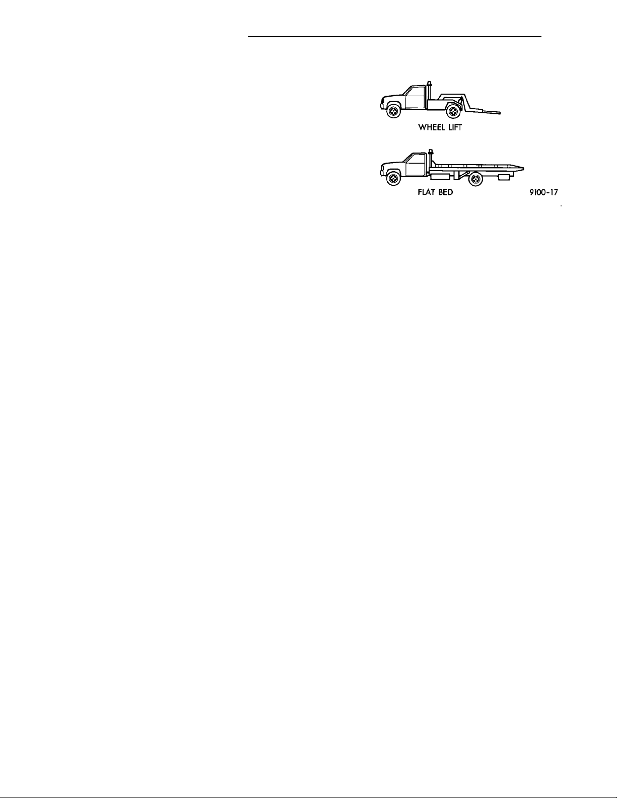
RECOMMENDED TOWING EQUIPMENT
To avoid damage to bumper fascia and air dams
use of a wheel lift or flat bed towing device (Fig. 2) is
recommended. When using a wheel lift towing device,
be sure the unlifted end of disabled vehicle has at
least 100 mm (4 in.) ground clearance. If minimum
ground clearance cannot be reached, use a towing
dolly. If a flat bed device is used, the approach angle
should not exceed 15 degrees.
GROUND CLEARANCE
CAUTION: If vehicle is towed with wheels
removed, install lug nuts to retain brake drums or
rotors.
A towed vehicle should be raised until lifted wheels
are a minimum 100 mm (4 in) from the ground. Be
sure there is adequate ground clearance at the opposite end of the vehicle, especially when towing over
Fig. 2 Recommended Towing Devices
rough terrain or steep rises in the road. If necessary,
remove the wheels from the lifted end of the vehicle
and lower the vehicle closer to the ground, to
increase the ground clearance at the opposite end of
the vehicle. Install lug nuts on wheel attaching studs
to retain brake drums or rotors.
LOCKED VEHICLE TOWING
When a locked vehicle must be towed with the
front wheels on the ground, use a towing dolly or flat
bed hauler.
FLAT TOWING WITH TOW BAR
• 3-speed automatic transaxle vehicles can be flat
towed at speeds not to exceed 40 km/h (25 mph) for
not more than 25 km (15 miles). The steering column
must be unlocked and gear selector in neutral.
• 5-speed manual transaxle vehicles can be flat
towed at any legal highway speed for extended distances. The gear selector must be in the neutral position.
TOWING—FRONT WHEEL LIFT
Chrysler Corporation recommends that a vehicle be
towed with the front end lifted, whenever possible.
TOWING—REAR WHEEL LIFT
If a vehicle cannot be towed with the front wheels
lifted, the rear wheels can be lifted provided the following guide lines are observed.
CAUTION: Do not use steering column lock to
secure steering wheel during towing operation.
• Unlock steering column and secure steering
wheel in straight ahead position with a clamp device
designed for towing.
• Verify that front drive line and steering components are in good condition.
• 5-speed manual transaxle vehicles can be towed
at any legal highway speed for extended distances.
The gear selector must be in the neutral position.
• 3-speed automatic transaxle vehicles can be
towed at speeds not to exceed 40 km/h (25 mph) for
Page 9
PL LUBRICATION AND MAINTENANCE 0 - 9
SERVICE PROCEDURES (Continued)
not more than 25 km (15 miles). The gear selector
must be in the neutral position.
HOISTING RECOMMENDATIONS
Refer to Owner’s Manual provided with vehicle for
proper emergency jacking procedures.
WARNING: THE HOISTING AND JACK LIFTING
POINTS PROVIDED ARE FOR A COMPLETE VEHICLE. WHEN THE ENGINE OR REAR SUSPENSION
IS REMOVED FROM A VEHICLE, THE CENTER OF
GRAVITY IS ALTERED MAKING SOME HOISTING
CONDITIONS UNSTABLE. PROPERLY SUPPORT OR
SECURE VEHICLE TO HOISTING DEVICE WHEN
THESE CONDITIONS EXIST.
CAUTION: Do not position hoisting device on suspension components, damage to vehicle can result.
Do not attempt to raise one entire side of the
vehicle by placing a floor jack midway between the
front and rear wheels. This practice may result in
permanent damage to the body.
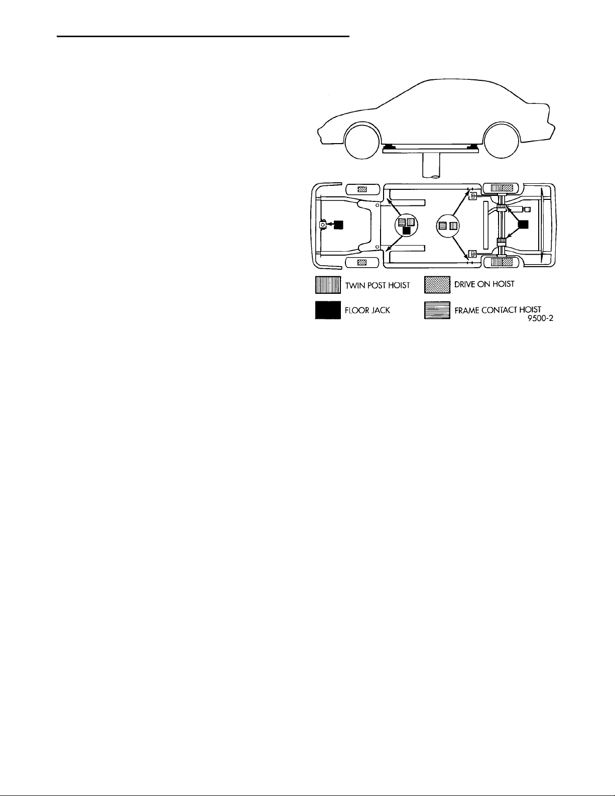
FLOOR JACK
When properly positioned, a floor jack can be used
to lift a PL vehicle (Fig. 3). Support the vehicle in the
raised position with jack stands.
A floor jack must never be used on any part of the
underbody.
HOIST
A vehicle can be lifted with:
• A single-post, frame-contact hoist.
• A twin-post, chassis hoist.
• A ramp-type, drive-on hoist.
NOTE: When a frame-contact type hoist is used,
verify that the lifting pads are positioned properly
(Fig. 3).
Fig. 3 Hoisting and Jacking Points
Page 10

 Loading...