

Page 1
ELM320
OBD (PWM) to RS232 Interpreter
Description
1238765
4
2
3
5
6
4
7
Features
Since the 1996 model year, North American
automobiles have been required to provide an OBD,
or On Board Diagnostics, port for the connection of
test equipment. Data is transferred serially between
the vehicle and the external equipment using these
connections, in a manner specified by the Society of
Automotive Engineers (SAE) standards. In addition
to operating at different voltage levels, these ports
also use a data format that is not compatible with the
standard used for personal computers.
The ELM320 is an 8 pin integrated circuit that is
able to change the data rate and reformat the OBD
signals into easily recognized ASCII characters. This
allows virtually any personal computer to
communicate with an OBD equipped vehicle using
only a standard serial port and a terminal program.
By also enhancing it with an interface program,
hobbyists can create their own custom ‘scan tool’.
This integrated circuit was designed to provide a
cost-effective way for experimenters to work with an
OBD system, so many features such as RS232
handshaking, variable baud rates, etc., have not
been implemented. In addition, this device is only
able to communicate using the 41.6KHz J1850 PWM
protocol that is commonly used in Ford Motor
Company vehicles.
• Low power CMOS design
• High current drive outputs - up to 25 mA
• Crystal controlled for accuracy
• Configurable with AT commands
• Standard ASCII character output
• High speed RS232 communications
• 41.6KHz J1850 PWM Protocol
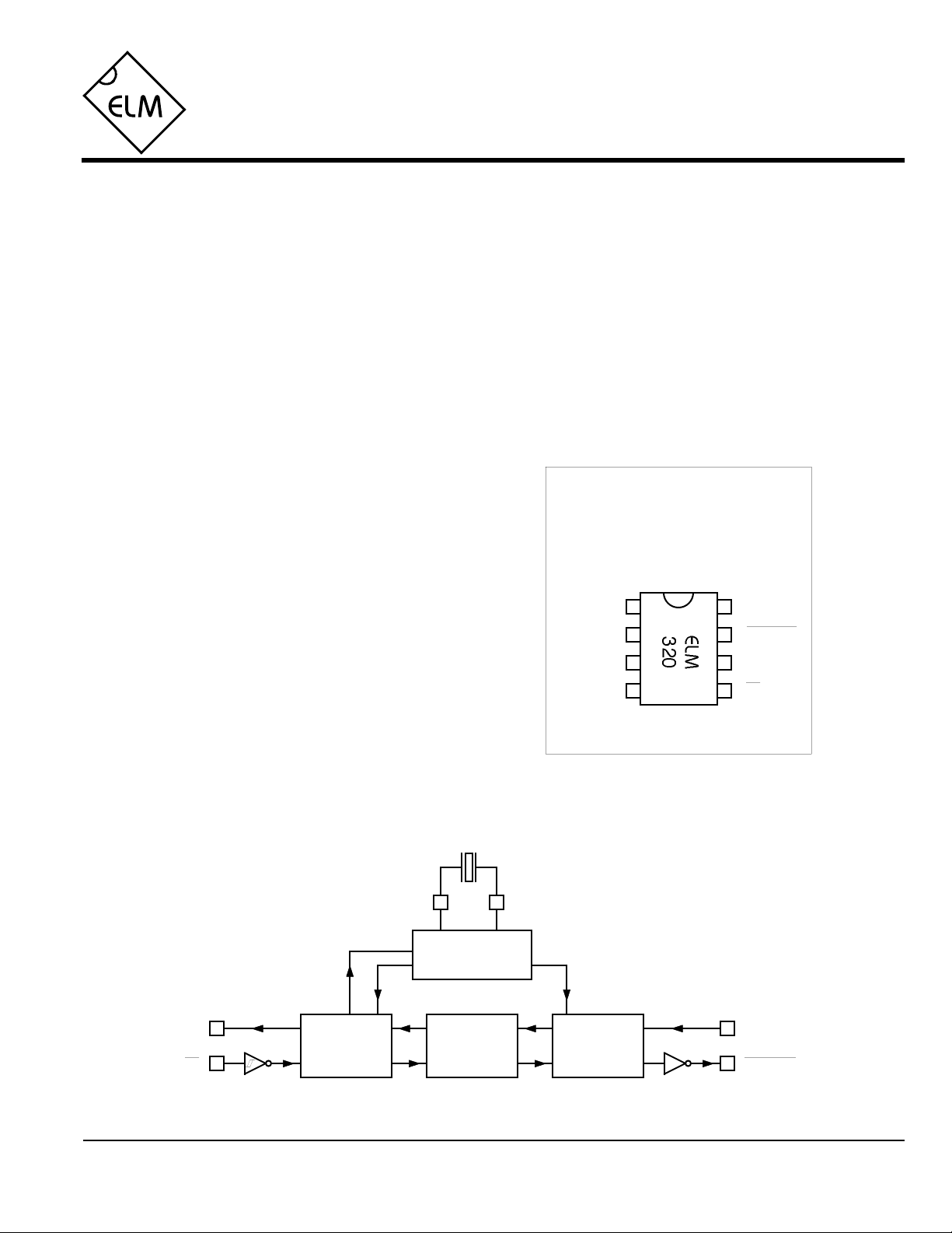
Connection Diagram
PDIP and SOIC
(top view)
VDD VSS
XT1
XT2
OBDIn Rx
OBDOut
Tx
Applications
• Diagnostic Trouble Code Readers
• Automotive Scan Tools
Block Diagram
Tx
Rx
ELM320DSB
3.58MHz
XT1 XT2
Timing and
Control
RS232
Interface
Interpreter
OBD
Interface
Elm Electronics – Circuits for the Hobbyist
< http://www.elmelectronics.com/ >
OBDIn
OBDOut
1 of 10
Page 2

ELM320
Pin Descriptions
VDD (pin 1)
This pin is the positive supply pin, and should
always be the most positive point in the circuit.
Internal circuitry connected to this pin is used to
provide power on reset of the microprocessor, so
an external reset signal is not required. Refer to
the Electrical Characteristics section for further
information.
XT1 (pin 2) and XT2 (pin 3)
A 3.579545MHz NTSC television colourburst
crystal is connected between these two pins.
Crystal loading capacitors (typically 27pF) will
also normally be connected between each of the
pins and the circuit common (Vss).
OBDIn (pin 4)
The OBD data is input to this pin, with a high
logic level representing the active state (and a
low, the passive). No Schmitt trigger input is
provided, so the OBD signal should be buffered
to minimize transition times for the internal
CMOS circuitry. The external level shifting
circuitry is usually sufficient to accomplish this –
see the Example Applications section for a
typical circuit.
Rx (pin5)
The computer’s RS232 transmit signal can be
directly connected to this pin from the RS232
line as long as a current limiting resistor
(typically about 47KΩ) is installed in series.
(Internal protection diodes will pass the input
currents safely to the supply connections,
protecting the ELM320.) Internal signal inversion
and Schmitt trigger waveshaping provide the
necessary signal conditioning.
Tx (pin 6)
The RS232 data output pin. The signal level is
compatible with most interface ICs, and there is
sufficient current drive to allow interfacing using
only a single PNP transistor, if desired.
OBDOut (pin 7)
This is the active low output signal which is used
to drive the OBD bus to its active state. Since the
J1850 PWM standard requires a differential bus
signal, the user must create the complement of
this signal to drive the other bus line. See the
Example Application section for more details.
VSS (pin 8)
Circuit common is connected to this pin. This is
the most negative point in the circuit.
Ordering Information
All rights reserved. Copyright 2001 - 2002 Elm Electronics.
Every effort is made to verify the accuracy of information provided in this document, but no representation or warranty can be
given and no liability assumed by Elm Electronics with respect to the accuracy and/or use of any products or information
described in this document. Elm Electronics will not be responsible for any patent infringements arising from the use of these
products or information, and does not authorize or warrant the use of any Elm Electronics product in life support devices and/or
systems. Elm Electronics reserves the right to make changes to the device(s) described in this document in order to improve
reliability, function, or design.
ELM320DSB
These integrated circuits are available in either the 300 mil plastic DIP format, or in the 200 mil SOIC surface
mount type of package. To order, add the appropriate suffix to the part number:
300 mil Plastic DIP............................... ELM320P 200 mil SOIC.....................................ELM320SM
Elm Electronics – Circuits for the Hobbyist
< http://www.elmelectronics.com/ >
2 of 10
Page 3
ELM320
Absolute Maximum Ratings
Storage Temperature.......................-65°C to +150°C
Ambient Temperature with
Power Applied....................................-40°C to +85°C
Note:
Stresses beyond those listed here will likely damage
the device. These values are given as a design
guideline only. The ability to operate to these levels
Voltage on VDD with respect to VSS............0 to +7.5V
is neither inferred nor recommended.
Voltage on any other pin with
respect to VSS........................... -0.6V to (VDD + 0.6V)
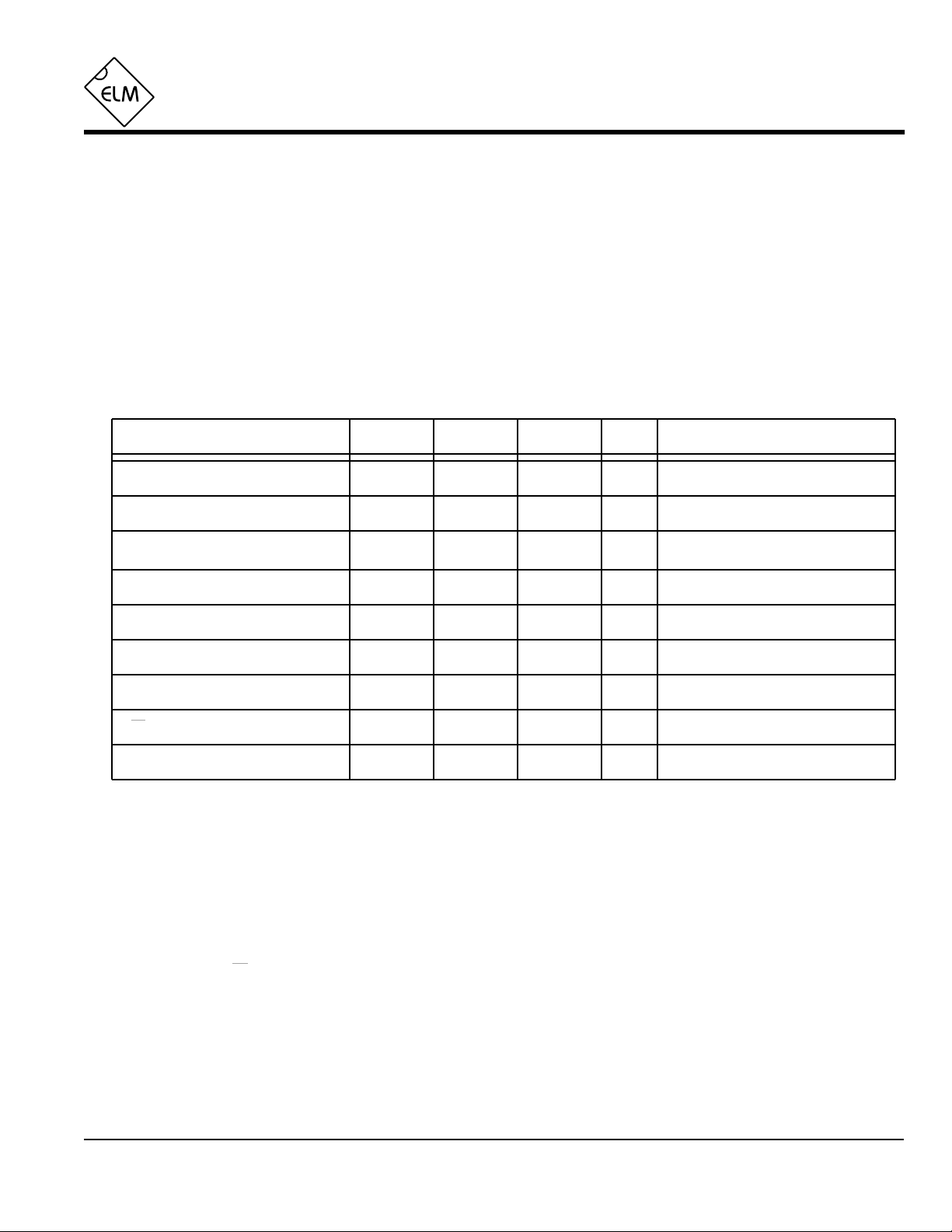
Electrical Characteristics
All values are for operation at 25°C and a 5V supply, unless otherwise noted. For further information, refer to note 1 below.
Characteristic Minimum Typical Maximum ConditionsUnits
Supply voltage, VDD 4.5 5.0 5.5 V
VDD rate of rise 0.05 V/ms
Average supply current, IDD 1.0 2.4 mA
Input low voltage VSS 0.15 VDD V
Input high voltage VDD V0.85 VDD
see note 2
see note 3
Output low voltage 0.6 V
Output high voltage VVDD - 0.7
Rx pin input current
RS232 baud rate
-0.5
+0.5
9600
Notes:
1. This integrated circuit is produced with a Microchip Technology Inc.’s PIC12C5XX as the core embedded
microcontroller. For further device specifications, and possibly clarification of those given, please refer to the
appropriate Microchip documentation (available at http://www.microchip.com/).
2. This spec must be met in order to ensure that a correct power on reset occurs. It is quite easily achieved
using most common types of supplies, but may be violated if one uses a slowly varying supply voltage, as
may be obtained through direct connection to solar cells, or some charge pump circuits.
3. Device only. Does not include any load currents.
4. This specification represents the current flowing through the protection diodes when applying large voltages
to the Rx input (pin 5) through a current limiting resistance. Currents quoted are the maximum that should be
allowed to flow continuously.
5. Nominal data transfer rate when a 3.58 MHz crystal is used as the frequency reference. Data is transferred
to and from the ELM320 with 8 data bits, no parity, and 1 stop bit (8 N 1).
mA
baud
Current (sink) = 8.7mA
Current (source) = 5.4mA
see note 4
see note 5
ELM320DSB
Elm Electronics – Circuits for the Hobbyist
< http://www.elmelectronics.com/ >
3 of 10
Page 4

ELM320
Communicating with the ELM320
The ELM320 relies on a standard RS232 type
serial connection to communicate with the user. The
data rate is fixed at 9600 baud, with 8 data bits, no
parity bit, 1 stop bit, and no handshaking (often
referred to as 9600 8N1). All responses from the IC
are terminated with only a single carriage return
character, and no line feed character. Some users
may wish to improve readability by configuring their
software to insert linefeed characters at the end of
each line.
Properly connected and powered, the ELM320 will
initially display the message:
ELM320 v1.1
>
In addition to identifying the version of the IC,
receipt of this string is a convenient way to be sure
that the computer connections and the settings are
correct. However, at this point no communications
have taken place with the vehicle, so the state of that
connection is still unknown.
The ‘>’ character displayed above is the ELM320’s
prompt character. It indicates that the device is in its
idle state, ready to receive characters on the RS232
port. Characters sent from the computer can either be
intended for the ELM320’s internal use, or for
reformatting and passing on to the vehicle’s OBD bus.
Commands for the ELM320 are distinguished from
those to the vehicle by always beginning with the
characters ‘AT’ (as is common with modems), while
commands for the OBD bus must contain only the
ASCII characters for hexadecimal digits (0 to 9 and A
to F). This allows the ELM320 to quickly determine
where the received characters are to be directed.
Whether an ‘AT’ type internal command or a hex
string for the OBD bus, all messages to the ELM320
must be terminated with a carriage return character
(hex ‘0D’) before it will be acted upon. The one
exception is when an incomplete string is sent and no
carriage return appears. In this case, an internal timer
will automatically abort the incomplete message after
about 10 seconds, and the ELM320 will print a single
question mark to show that the input was not
understood (and was not acted upon).
Messages that are misunderstood by the ELM320
(syntax errors) will always be signalled by a single
question mark (‘?’). These include incomplete
messages, invalid AT commands, or invalid
hexadecimal digit strings. It is not an indication of
whether or not the message was understood by the
vehicle. (The ELM320 is a protocol interpreter that
makes no attempt to assess OBD messages for
validity - it only ensures that an even number of hex
digits were received, combined into bytes, and sent
out the OBD port, so it cannot determine if the
message sent to the vehicle is in error.)
Incomplete or misunderstood messages can also
occur if the controlling computer attempts to write to
the ELM320 before it is ready to accept the next
command (as there are no handshaking signals to
control the data flow). To avoid a data overrun, users
should always wait for the prompt character (‘>’)
before issuing the next command.
Finally, a few convenience items to note. The
ELM320 is not case-sensitive, so ‘ATZ’ is equivalent to
‘atz’, and to ‘AtZ’. The device ignores space characters
as well as control characters (tab, linefeed, etc.) in the
input, so they can be inserted anywhere to improve
readability and, finally, issuing only a single carriage
return character will repeat the last command (making
it easier to request updates on dynamic data such as
engine rpm).
AT Commands
commands in much the same manner that modems
do. Any message received, at any time, that begins
with the character ‘A’ followed by the character ‘T’ will
be considered an internal configuration or ‘AT’
command. These are executed upon receipt of the
terminating carriage return character, and successful
completion of the command is acknowledged by the
printing of the characters ‘OK’.
ELM320DSB Elm Electronics – Circuits for the Hobbyist
The ELM320 accepts internal configuration
< http://www.elmelectronics.com/ >
Communications on the OBD bus can generally
begin without requiring the issuance of any AT
commands, as the factory default settings should be
appropriate for most applications. Occasionally the
user may wish to customize settings, such as turning
the character echo off, etc. In these cases, AT
commands must be issued.
The following is a summary of the AT commands
that are recognized by the current version of the
4 of 10
Page 5

ELM320
ELM320. Note that they are not case-sensitive, and
that the character ‘0’ is the number ‘zero’:
ATE0 and ATE1
These commands control whether characters
received on the RS232 port are retransmitted (or
echoed) back to the host computer. To reduce traffic
on the RS232 bus, users may wish to turn echoing
off by issuing ATE0. Echo is initially on at powerup
(default) and can be turned on at any time by issuing
ATE1.
ATH0 and ATH1
These commands control whether or not the header
OBD Commands
information is shown in the responses. All OBD
messages have an initial (header) string of three
bytes and a trailing check digit (CRC character) that
is normally not displayed by the ELM320. To see this
extra information, users should turn headers on by
issuing ATH1. The default is H0 (headers off).
ATZ
This combination causes the chip to perform a
complete reset as if power were cycled off and then
on again. All settings are returned to their default
values, and the chip will be put in the idle state,
waiting for characters on the RS232 bus.
If the bytes received on the RS232 bus do not
begin with the letters A and T, they are assumed to be
commands for the vehicle’s OBD bus. The bytes will
be tested to ensure that they are valid pairs of
hexadecimal digits and, if they are, will be combined
into bytes for transmitting. Recall that no checks are
made as to the validity of the OBD command – data is
simply retransmitted as received.
OBD commands are actually sent to the vehicle
embedded in a data message. The standards require
that every message begin with three header bytes and
end with a checksum byte, which the ELM320 adds
automatically for the user (the header bytes never
change in value, so are stored internally). To view the
extra bytes that are received with the vehicle’s
messages, issue an ATH1 internal command.
Most OBD commands to the vehicle are one or
two bytes in length, but some can be three or more
bytes long. As the ELM320 is considered an
experimenter’s circuit, it will only accept a maximum of
three command bytes (or six hexadecimal digits) per
message. Attempts to send more will result in a syntax
error, with the entire command being ignored and a
single question mark being printed.
The use of hexadecimal digits for all of the data
exchange was chosen as it is the most common data
format used in the relevant SAE standards. It is
consistent with mode request listings and is the most
frequently used format for displaying results. With a
little practice, it should not be very difficult to deal in
hex numbers, but some people may want to obtain a
conversion table or keep a calculator nearby. All users
will be required to manipulate the results in some way,
though (combine bytes and divide by 4 to obtain rpm,
divide by 2 to obtain degrees of advance, etc.), and
may find a software front-end helpful.
As an example of sending a command to the
vehicle, assume that A6 (or decimal 166) is the
command that is required to be sent. In this case, the
user would type the letter A, then the number 6, then
would press the return key. These three characters
would be sent to the ELM320 on the RS232 bus. The
ELM320 would store the characters as they are
received, and when the third character (the carriage
return) is received, begin to assess the other two. It
would see that they are both valid hex digits, and
would convert them to a one byte value (decimal value
is 166). Four header bytes would be added, and a total
of five bytes would be sent to the vehicle. Note that the
carriage return character is only a signal to the
ELM320, and is not sent to the vehicle.
After sending a command, the ELM320 listens on
the OBD bus for any responses that are directed to it.
Each received byte is converted to the equivalent
hexadecimal pair of ASCII characters and transmitted
on the RS232 port for the user. Rather than send
control characters which are unprintable on most
terminals, the digits are sent as numbers and letters
(eg. the hex digit ‘A’ is transmitted as decimal value
65, and not 10).
If there was no response from the vehicle, due to
no data being available, or because the command is
not supported, a ‘NO DATA’ message will be sent. See
the error messages section for a description of this
message and others.
ELM320DSB Elm Electronics – Circuits for the Hobbyist
5 of 10
< http://www.elmelectronics.com/ >
Page 6

ELM320
Talking to the Vehicle
The ELM320 cannot be directly connected to a
vehicle as it is, but needs support circuitry as shown in
the Example Applications section. Once incorporated
into such a circuit, one need only use a terminal
program to send bytes to, and receive them from the
vehicle via the ELM320.
SAE standards specify that command bytes sent
to the vehicle must adhere to a set format. The first
byte (known as the ‘mode’) always describes the type
of data being requested, while the second, third, etc.
bytes specify the actual information required (given by
a ‘parameter identification’ or PID number). The
modes and PIDs are described in detail in the SAE
documents J1979 and J2190, and may also be
expanded on by the vehicle manufacturers.
Normally, one is only concerned with the nine
diagnostic test modes described in J1979 (although
there is provision for more). Note that it is not a
requirement for all of them to be supported. These are
the nine modes:
01 : show current data
02 : show freeze frame data
03 : show diagnostic trouble codes
04 : clear trouble codes and stored values
05 : test results, oxygen sensors
06 : test results, non-continuously monitored
07 : test results, continuously monitored
08 : special control mode
09 : request vehicle information
Within each mode, PID 00 is normally reserved to
show which PIDs are supported by that mode. Mode
01, PID 00 must be supported by all vehicles, and can
be accessed as follows…
Ensure that the ELM320 is properly connected to
your vehicle, and powered. Most vehicles will not
respond without the ignition key in the ON position, so
turn the ignition on, but do not start the vehicle. At the
prompt, issue the mode 01 PID 00 command:
>01 00
A typical response could be as follows:
41 00 BE 1F B8 10
The 41 00 signifies a response (4) from a mode 1
request from PID 00 (a mode 2, PID 00 request is
answered with a 42 00, etc.). The next four bytes (BE,
1F, B8, and 10) represent the requested data, in this
case a bit pattern showing which of PIDs 1 through 32
are supported by this mode (1=supported, 0=not).
Although this information is not very useful for the
casual user, it does serve to show that you are
communicating with the vehicle.
Another example requests the current engine
coolant temperature (ECT). This is PID 05 in mode 01,
and is requested as follows:
>01 05
The response will be of the form:
41 05 7B
This shows a mode 1 response (41) from PID 05,
with value 7B. Converting the hexidecimal 7B to
decimal, one gets 7 x 16 + 11 = 123. This represents
the current temperature in degrees Celsius, with the
zero value offset to allow operation at subzero
temperatures. To convert to the actual coolant
temperature, simply subtract 40 from the value. In this
case, then, the ECT is 123 - 40 = 83 deg C.
A final example shows a request for the OBD
requirements to which this vehicle was designed. This
is PID 1C of mode 01, so at the prompt, type:
>01 1C
A typical response would be:
41 1C 01
The returned value (01) shows that this vehicle
conforms to OBDII (California ARB) standards. The
presently defined responses are :
01 : OBDII (California ARB)
02 : OBD (Federal EPA)
03 : OBD and OBDII
04 : OBD I
05 : not intended to meet any OBD requirements
06 : EOBD (Europe)
Some modes may provide multi-line responses
(09, if supported, can display the vehicle’s serial
number). The ELM320 will attempt to display all
responses in these cases, but only if it is allowed
sufficient time to process each. There may be
occasions when the vehicle responds too quickly to
allow time for reprocessing, and lines could be lost.
Hopefully this has shown how typical requests
proceed. It has not been meant to be a definitive
source on modes and PIDs – this information can be
obtained from the SAE (http://www.sae.org/), from the
manufacturer of your vehicle, ISO (http://iso.org/), or
from various other sources on the web.
ELM320DSB Elm Electronics – Circuits for the Hobbyist
6 of 10
< http://www.elmelectronics.com/ >
Page 7

Interpreting Trouble Codes
ELM320
Likely the most common use that the ELM320 will
be put to is in obtaining the current Diagnostic Trouble
Codes or DTCs. Minimally, this requires that a mode
03 request be made, but first one should determine
how many trouble codes are presently stored. This is
done with a mode 01 PID 01 request as follows:
>01 01
To which a typical response might be:
41 01 81 07 65 04
The 41 01 signifies a response to our request, and
the first data byte (81) is the result that we are looking
for. Clearly there would not be 81(hex) or 129(decimal)
trouble codes if the vehicle is operational. In fact, this
byte does double duty, with the most significant bit
being used to indicate that the malfunction indicator
lamp (MIL, or ‘Check Engine’) has been turned on by
one of this module’s codes (if there are more than
one), while the other 7 bits provide the actual number
of stored codes. To determine the number of stored
codes then, one needs to subtract 128 (or 80 hex)
from the number if it is greater than 128, and otherwise
simply read the number of stored codes directly.
The above response then indicates that there is
one stored code, and it was the one that set the Check
Engine Lamp or MIL on. The remaining bytes in the
response provide information on the types of tests
supported by that particular module (see SAE
document J1979 for further information).
In this instance, there was only one line to the
response, but if there were codes stored in other
modules, they each could have provided a line of
response. To determine which module is reporting the
trouble code, one would have to turn the headers on
(ATH1) and then look at the third byte of the three byte
header for the address of the module that sent the
information.
Having determined the number of codes stored,
the next step is to request the actual trouble codes
with a mode 03 request:
>03
A response to this could be:
43 01 33 00 00 00 00
The ‘43’ in the above response simply indicates
that this is a response to a mode 03 request. The other
6 bytes in the response have to be read in pairs to
show the trouble codes (the above would be
interpreted as 0133, 0000, and 0000). Note that there
is only one trouble code here. The response has been
padded with 00’s as is required by the standard, and
the extra 0000’s do not represent actual trouble codes.
As was the case when requesting the number of
stored codes, the most significant bits of each trouble
code also contain additional information. It is easiest to
use the following table to interpret the first digit of
trouble codes as follows:
If the first hex digit received is this,
Replace it with these two characters
P0
0
P1
1
P2
2
P3
3
C0
4
C1
5
C2
6
C3
7
B0
8
B1
9
B2
A
B3
B
U0
C
U1
D
U2
E
U3
F
Taking the example trouble code (0133), the first
digit (0) would then be replaced with P0, and the 0133
reported would become P0133 (which is the code for
an ‘oxygen sensor circuit slow response’). As for
further examples, if the response had been D016, the
code would be interpreted as U1016, while a 1131
would be P1131.
Had there been codes stored by more than one
module, or more than three codes stored in the same
module, the above response would have consisted of
multiple lines. To determine which module is reporting
each trouble would then require turning the headers on
with an ATH1 command.
Powertrain Codes - SAE defined
“ “ - manufacturer defined
“ “ - SAE defined
“ “ - jointly defined
Chassis Codes - SAE defined
“ “ - manufacturer defined
“ “ - manufacturer defined
“ “ - reserved for future
Body Codes - SAE defined
“ “ - manufacturer defined
“ “ - manufacturer defined
“ “ - reserved for future
Network Codes - SAE defined
“ “ - manufacturer defined
“ “ - manufacturer defined
“ “ - reserved for future
ELM320DSB Elm Electronics – Circuits for the Hobbyist
7 of 10
< http://www.elmelectronics.com/ >
Page 8

ELM320
Resetting Trouble Codes
The ELM320 is quite capable of resetting
diagnostic trouble codes, as this only requires issuing
a mode 04 command. The consequences should
always be considered before sending it, however, as
more than the MIL (or ‘Check Engine’ lamp) will be
reset. In fact, issuing a mode 04 will:
- reset the number of trouble codes
- erase any diagnostic trouble codes
- erase any stored freeze frame data
- erase the DTC that initiated the freeze frame
- erase all oxygen sensor test data
- erase mode 06 and 07 test results
Clearing of all of this information is not unique to
the ELM320, as it occurs whenever a scan tool is used
to reset your codes. Understand that the loss of this
data could cause your car to run poorly for a short time
as well, while the system recalibrates itself.
Error Messages
To avoid inadvertently erasing stored information,
the SAE specifies that scan tools must verify that a
mode 04 is intended (“Are you sure?”) before actually
sending it to the vehicle, as all trouble code
information is immediately lost when the mode is sent.
Recall that the ELM320 does not monitor the content
of messages, so it will not know to ask for confirmation
of the mode request - this would have to be the duty of
a software interface if one is written.
As stated, to actually erase diagnostic trouble
codes, one need only issue a mode 04 command. A
response of 44 from the vehicle indicates that the
mode request has been carried out, the information
erased, and the MIL turned off. Some vehicles may
require a special condition to occur (the ignition on but
the engine not running, etc.) before it will respond to a
mode 04 command.
That is all there is to clearing the codes. Once
again, be very careful not to inadvertently issue an 04!
When hardware or data problems are
encountered, the ELM320 will respond with one of
the following short messages. Here is a brief
description of each:
BUS BUSY
The ELM320 tried to send the mode command or
request for about 0.5 seconds without success.
Messages are all assigned priorities, which allows
one message to take precedence over another.
More important things may have been going on, so
try re-issuing your request.
BUS ERROR
An attempt was made to send a message, and the
data bus voltage did not respond as expected. This
could be because of a circuit short or open, so
check all of your connections and try once more.
DATA ERROR
There was a response from the vehicle, but the
information could not be recovered. Most likely it
did not contain enough bytes to be a valid
message, which can occur if a ‘Break’ signal is
issued by another module.
<DATA ERROR
The error check result (CRC byte) was not as
expected, indicating a data error in the line pointed
to (the ELM320 still shows you what it received).
There could have been a noise burst which
interfered, or a circuit problem. Try resending the
request.
NO DATA
There was no response from the vehicle. The mode
requested may not be supported, so the vehicle
ignored you, or possibly the key needs to be turned
on. Try issuing a 01 00 command to be sure that the
vehicle is ready to receive commands.
?
This is the standard response for a misunderstood
command received on the RS232 bus. Usually it is
due to a typing mistake.
ELM320DSB Elm Electronics – Circuits for the Hobbyist
8 of 10
< http://www.elmelectronics.com/ >
Page 9

Example Application
ELM320
The SAE J1962 standard dictates that all OBD
compliant vehicles must provide a standard connector
near the driver’s seat, the shape and pinout of which is
shown in Figure 1 below. The circuitry described here
will be used to connect to this plug without modification
to your vehicle.
The male J1962 connector required to mate with a
vehicle’s connector may be difficult to obtain in some
locations, and you could be tempted to improvise by
making your own connections to the back of your
vehicle’s connector. If doing so, we recommend that
you do nothing which would compromise the integrity
of your vehicle’s OBD network. The use of any
connector which could easily short pins (such as an
RJ11 type telephone connector) would definitely not
be recommended.
The circuit of Figure 2 on the next page shows
how the ELM320 would typically be used. Circuit
power has been obtained from the vehicle (via OBD
pins 16 and 5) and, after some minor filtering, is
presented to a five volt regulator. The output of this
regulator powers several points in the circuit as well as
an LED (for visual confirmation that power is present).
The remaining two connections to the vehicle
(OBD pins 2 and 10) are for the differential data
system specified by the J1850 PWM standard. When
no data is being transmitted, both wires are idle with
the transistor drivers off, and the resistive pullup and
pulldown allowing voltage levels to float to the supply
levels. Note that the PNP driver transistor, and the
2.7KΩ pullup resistor both have series protection
diodes to prevent backfeeds into the ELM320 circuitry.
The ELM320 has only one OBD data ouput line
(pin 7). It is an active low signal, so must be used to
drive the open-collector ‘Bus +’ signal via the PNP
transistor as shown. By using a portion of this same
signal to drive the NPN transistor for the ‘Bus -’ signal,
one obtains open collector differential drive.
Data is received from the OBD bus and level
shifted by the NPN/PNP transistor pair shown
connected to pin 4 of the ELM320. The NPN transistor
detects the differential data signal while allowing for
the presence of common mode voltages, and the PNP
transistor provides the 0 to 5 volt levels required by
OBDIn.
A very basic RS232 interface is shown connected
to pins 5 and 6 of the ELM320. This circuit ‘steals’
power from the host computer in order to provide a full
swing of the RS232 voltages without the need for a
negative supply. The RS232 pin connections shown
are for a 25 pin connector. If you are using a 9 pin, the
connections would be 2(RxD), 5(SG) and 3(TxD).
RS232 data from the computer is directly
connected to pin 5 of the IC through only a 47KΩ
current limiting resistor. This resistor allows for voltage
swings in excess of the supply levels while preventing
damage to the ELM320. A single 100KΩ resistor is
also shown in this circuit so that pin 5 is not left floating
if the computer is disconnected.
Transmission of RS232 data is via the single PNP
transistor connected to pin 6. This transistor allows the
output voltage to swing between +5V and the negative
voltage stored on the 0.1µF capacitor (which is
charged by the computer’s TxD line). Although it is a
simple connection, it is quite effective for this type of
application.
Finally, the crystal shown connected between pins
2 and 3 is a common TV type that can be easily and
inexpensively obtained. The 27pF crystal loading
capacitors shown are typical only, and you may have
to select other values depending on what is specified
for the crystal you obtain.
This completes the description of the circuit. While
it is the minimum required to talk to an OBD equipped
vehicle (it relies on such techniques as using the
internal current limiting of the 78L05 for circuit
protection, etc.), it is a fully functional circuit. As an
experimenter, you may want to expand on it, though,
providing more protection from faults and electrostatic
discharge, or providing a different interface for the
RS232 connection to the computer. Then perhaps a
Basic program to make it easier to talk to the vehicle,
and a method to log your findings, and…
1
9
Figure 1. Vehicle Connector
8
16
ELM320DSB Elm Electronics – Circuits for the Hobbyist
9 of 10
< http://www.elmelectronics.com/ >
Page 10

ELM320
1234876
5
OBD
Interface
16
(Battery
Positive)
5
(Signal
Ground)
2
(Bus +)
10
(Bus -)
+5V
0.47µF
78L05
+5V
4.7KΩ
10KΩ
+5V
750Ω
4.7KΩ
+5V
0.01µF
‘Power On’
LED
Notes: -
NPN transistors are
2N3904 or similar
-
PNP transistors are
2N3906 or similar
-
Diodes are 1N4148 or
1N4001, etc.
4.7KΩ
10KΩ
2.7KΩ2.7KΩ
27pF
+5V
+5V
3.58MHz
27pF
4.7KΩ
Figure 2. Typical OBD to RS232 Interface
47KΩ
+5V
RS232
Interface
10KΩ
3 (RxD)
4.7KΩ
0.1µF
7 (SG)
2 (TxD)
100KΩ
ELM320DSB Elm Electronics – Circuits for the Hobbyist
< http://www.elmelectronics.com/ >
10 of 10
 Loading...