

Page 1
EC49016
Standalone Linear Lithium Battery Charger
Introduction
(General Description)
EC49016 is a complete constant-current & constant
voltage linear charger for single cell lithium-ion
batteries. Its SOT-23 package and low external
component count make EC49016 ideally suited for
portable applications. Furthermore, the EC49016 is
specifically designed to work within USB power
specification. At the same time, EC49016 can also be
used in the standalone lithium-ion battery charger.
No external sense resistor is needed, and no
blocking diode is required due to the internal MOSFET
architecture. Thermal feedback regulates the charger
current to limit the die temperature during high power
operation or high ambient temperature. The charge
voltage is fixed at 4.2V, and the charge current can be
programmed externally with a single resistor. The
EC49016 automatically terminates the charge cycle
when the charge current drops to 1/10
programmed value after the final float voltage is
reached.
When the input supply (wall adapter or USB supply)
is removed, the EC49016 automatically enters a low
current stage, dropping the battery drain current to less
than 2μA. The EC49016 can be put into shutdown
mode, reducing the supply current to 20μA.
Other features include charge current monitor,
under-voltage lockout, automatic recharge and a status
pin to indicate charge termination and the presence of
an input voltage.
Ordering/Marking Information
th
the
Features
z Programmable Charge Current Up to 800mA
z No MOSFET, Sense Resistor or Blocking Diode
Required
z Constant-Current/Constant-Voltage Operation
with Thermal Protection to Maximize Charge
Rate without Risk of Overheating
z Charges Single Cell Li-ion Batteries Directly
from USB Port
z Preset 4.2V Charge Voltage with +-1% Accuracy
z 20μA Supply Current in Shutdown
z 2.9V Trickle Charge Threshold
z Available Without Trickle Charge
z Soft-Start Limits Inrush Current
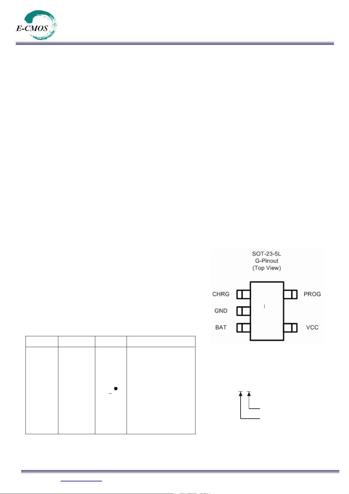
z Available in 5-Lead SOT-23 Package
Applications
z Cellular Telephones, PDA, MP3 Players
z Charging Docks and Cradles
z Bluetooth Applications
Pin Configuration
016b*
Package Part Number Marking Marking Information
Starting with 6, a bar on top
of 6 is for production year 2005,
and underlined 6 is for year
2006. The naming pattern
SOT-23-5L
EC49016B2-F 016
continues with consecutive
b
characters for later years.
The last character is the week
code. (A-Z: 1-26, a-z: 27-52)
A dot on top right corner is for
lead-free process.
E-CMOS Corp. (www.ecmos.com.tw
) Page 1 of 8 2006/05/18
Ordering Information
EC49016X - F
F: Lead-Free
Package: B2 = SOT-23-5L
Page 2
EC49016
Standalone Linear Lithium Battery Charger
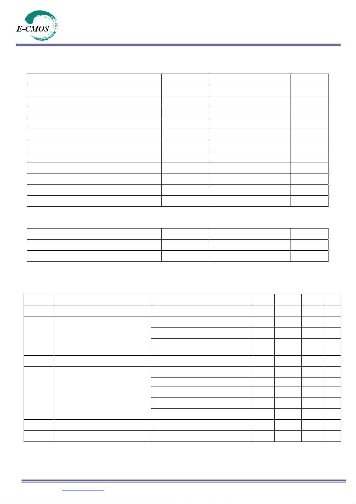
Absolute Maximum Rating
Parameter Symbol Value Units
Input Supply Voltage VCC 8 V
PROG Voltage V
BAT Voltage V
CHRG Voltage V
BAT Short-Circuit Duration — Continuous —
Thermal Resistance, Junction-to-Ambient ΘJA 250 (SOT-23-5) °C/W
BAT Pin Current I
PROG Pin Current I
Maximum Junction Temperature TJ 125 °C
Storage Temperature TS -65 to +125 °C
Lead Temperature (Soldering, 10 sec) — 300 °C
(1)
VCC+0.3 V
PROG
7 V
BAT
10 V
CHRG
800 mA
BAT
800
PROG
μA
(2)
Recommended Operating Conditions
Parameter Symbol Value Units
Supply Input Voltage VIN -0.3 to +8 V
Junction Temperature TJ -40 to +85 °C
Electrical Characteristics
VIN = 5V; TJ = 25°C; unless otherwise specified.
Symbol Parameter
VCC Input Supply Voltage 4.25 — 6 V
Charge Mode
ICC
V
Regulated Output (Float) Voltage I
FLOAT
I
BAT
I
Trickle Charge Current V
TRIKL
V
Trickle Charge Threshold Voltage R
TRIKL
Input Supply Current
BAT Pin Current
Standby Mode (Charge Terminated)
Shutdown Mode(R
R
R
Standby Mode, VBAT = 4.2V
Shutdown Mode (R
Conditions Min Typ Max Unit
(3)
, R
PROG
< V
V
CC
= 30mA, I
BAT
PROG
PROG
Sleep Mode, V
< V
BAT
PROG
, or VCC < VUV)
BAT
CHRG
= 10k, Current Mode 90 110 130 mA
= 2k, Current Mode — 500 — mA
PROG
, R
TRIKL
= 10k, V
= 10k — 110 500 µA
PROG
—
115 160 µA
Not Connected,
= 5mA 4.158 4.2 4.242 V
Not Connected)
= 0V
CC
= 10k 12 18 25 mA
PROG
Rising 2.8 2.9 3.0 V
BAT
—
0 +/-1 +/-5
— +/-0.5 +/-5
— +/-1 +/-5
20 40 µA
µA
µA
µA
E-CMOS Corp. (www.ecmos.com.tw
) Page 2 of 8 2006/05/18
Page 3
EC49016
Standalone Linear Lithium Battery Charger
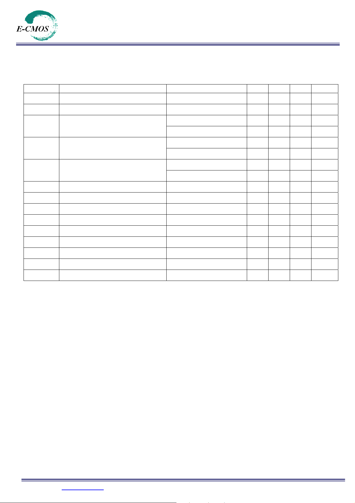
Electrical Characteristics (Continued)
= 5V; TJ = 25°C; unless otherwise specified
V
IN
Symbol Parameter Conditions Min Typ Max Unit
VUV VCC Undervoltage Lockout Threshold From V
V
ΔV
V
UVHYS
MSD
ASD
TERM
V
PROG Pin Voltage R
PROG
I
CHRG Pin Weak Pull-Down Current V
CHRG
V
CHRG Pin Output Low Voltage I
CHRG
RECHRG
T
Thermal Protection Temperature — 120 — °C
LIM
Undervoltage Lockout Hysteresis — 170 — mV
CC
Manual Shutdown Threshold Voltage
V
– V
CC
C/10 Termination Current Threshold
Recharge Battery Threshold Voltage V
Lockout Threshold Voltage
BAT
PROG
PROG Pin Rising — 1.25 — V V
PROG Pin Falling
V
CC
V
CC
Low to High — 3.4 — V
CC
—
1.2
from Low to High — 100 — mV V
—
—
30
0.1
from High to Low
R
PROG
R
PROG
= 10k, Current Mode 0.9 1.03 1.1 V
CHRG
CHRG
- V
FLOAT
(4)
= 10k
= 5mA — 0.35 0.8 V
— 0.1 — mA/mAI
= 2k
= 5V 8 20 40 µA
— 100 — mV
RECHRG
—
—
—
V
mV
mA/mA
tSS Soft-Start Time I
t
RECHARGE
t
I
Note 1: Exceeding the absolute maximum rating may damage the device.
Note 2: The device is not guaranteed to function outside its operating rating.
Note 3: Supply current includes PROG pin current (approximately 100µA) but does not include any current delivered to the
Note 4: I
Recharge Comparator Filter Time V
Termination Comparator Filter Time I
TERM
PROG Pin Pull-Up Current — 1 — µA
PROG
battery through the BAT pin (approximately 100mA).
is expressed as a fraction of measured full charge current with indicated PROG resistor.
TERM
= 0 to 1000V/R
BAT
High to Low — 2 — ms
BAT
Falling Below I
BAT
— 100 — µs
PROG
/10 — 1000 — µs
CHG
E-CMOS Corp. (www.ecmos.com.tw
) Page 3 of 8 2006/05/18
Page 4

EC49016
Standalone Linear Lithium Battery Charger
Typical Performance Characteristics
4.230
4.225
4.220
4.215
4.210
(V)
4.205
BAT
V
4.200
4.195
4.190
4.185
Float Voltage vs Supply Voltage
R
=10k
PROG
=25
T
℃
A
4.0 4.5 5.0 5.5 6.0 6.5
V
(V)
CC
Figure 1. Figure 2.
70
Trickle Charge Current vs Supply Voltage
60
50
40
30
(mA)
TRIKL
I
20
10
R
PROG
R
=2k
PROG
=10k
V
=2.5V
BAT
T
=25
℃
A
Charge Current vs Supply Voltage
600
500
400
300
(m A )
BAT
I
200
100
0
4.04.55.05.56.06.57.0
4.215
4.210
4.205
(V)
4.200
FLOAT
V
4.195
4.190
R
=2k
PROG
ONSET OF
V
=4V
BAT
=25
T
℃
A
THE RM AL
REGULATION
=10k
R
PROG
V
(V)
CC
Float Voltage vs Temperature
0
4.0 4.5 5.0 5.5 6.0 6.5 7.0
Figure 3. Figure 4.
Application Diagram
4.5V to 6.5V
LED
330
EC49016
CHRG
600mA Single Cell Li-Ion Charger
VIN
VCC
GND
V
CC
BAT
PROG
(V)
4.185
20 40 60 80 100 120
Temperature (℃)
600mA
4.2V
Li-Ion
Battery
1.65K
E-CMOS Corp. (www.ecmos.com.tw
) Page 4 of 8 2006/05/18
Page 5

EC49016
Standalone Linear Lithium Battery Charger
Operation
The EC49016 is a single cell lithium-ion battery charger using a constant-current/constant-voltage algorithm. It can
deliver up to 800mA of charge current (using a good thermal PCB layout) with a final float voltage accuracy of ±1%.
The EC49016 includes an internal P-channel power MOSFET and thermal regulation circuitry. No blocking diode or
external current sense resistor is required; thus, the basic charger circuit requires only two external components.
Furthermore, the EC49016 is capable of operating from a USB power source.
Normal Charge Cycle
A charge cycle begins when the voltage at the VCC pin rises above the UVLO threshold level and a 1% program
resistor is connected from the PROG pin to ground or when a battery is connected to the charger output. If the BAT pin
is less than 2.8V, the charger enters trickle charge mode. In this mode, the EC49016 supplies approximately 1/10 the
programmed charge current to bring the battery voltage up to a safe level for full current charging.
When the BAT pin voltage rises above 2.8V, the charger enters constant-current mode, where the programmed charge
current is supplied to the battery. When the BAT pin approaches the final float voltage (4.2V), the EC49016 enters
constant-voltage mode and the charge current begins to decrease. When the charge current drops to 1/10 of the
programmed value, the charge cycle ends.
Programming Charge Current
The charge current is programmed using a single resistor from the PROG pin to ground. The battery charge current is
1100 times the current out of the PROG pin. The program resistor and the charge current are calculated using the
following equations:
V
I
BAT
1100
I
CHG
V
R
,
I
PROG
PROG
R
PROG
The charge current out of the BAT pin can be determined at any time by monitoring the PROG pin voltage using the
following equation:
CHG
==
1100•=
1100
R
PROG
V
,
Charge Termination
A charge cycle is terminated when the charge current falls to 1/10th the programmed value after the final float voltage
is reached. This condition is detected by using an internal, filtered comparator to monitor the PROG pin. When the
PROG pin voltage falls below 100mV for longer than t
latched off and the EC49016 enters standby mode, where the input supply current drops to 200mA. (Note: C/10
termination is disabled in trickle charging and thermal limiting modes).When charging, transient loads on the BAT pin
can cause the PROG pin to fall below 100mV for short periods of time before the DC charge current has dropped to
1/10th the programmed value. The 1ms filter time (t
this nature do not result in premature charge cycle termination. Once the average charge current drops below 1/10th
the programmed value, the EC49016 terminates the charge cycle and ceases to provide any current through the BAT
pin. In this state, all loads on the BAT pin must be supplied by the battery.The EC49016 constantly monitors the BAT
pin voltage in standby mode. If this voltage drops below the 4.05V recharge threshold (V
begins and current is once again supplied to the battery. To manually restart a charge cycle when in standby mode, the
input voltage must be removed and reapplied, or the charger must be shut down and restarted using the PROG pin.
Figure 1 shows the state diagram of a typical charge cycle.
(typically 1ms), charging is terminated. The charge current is
TERM
) on the termination comparator ensures that transient loads of
TERM
), another charge cycle
RECHRG
E-CMOS Corp. (www.ecmos.com.tw
) Page 5 of 8 2006/05/18
Page 6

EC49016
Standalone Linear Lithium Battery Charger
Charge Status Indicator (CHRG)
The charge status output has three different states: strong pull-down (~10mA), weak pull-down (~20μA) and high
impedance. The strong pull-down state indicates that the EC49016 is in a charge cycle. Once the charge cycle has
terminated, the pin state is determined by undervoltage lockout conditions. A weak pull-down indicates that V
the UVLO conditions and the EC49016 is ready to charge. High impedance indicates that the EC49016 is in
undervoltage lockout mode: either V
to the V
pin.
CC
is less than 100mV above the BAT pin voltage or insufficient voltage is applied
CC
meets
CC
Thermal Limiting
An internal thermal feedback loop reduces the programmed charge current if the die temperature attempts to rise
above a preset value of approximately 120℃. This feature protects the EC49016 from excessive temperature and
allows the user to push the limits of the power handling capability of a given circuit board without risk of damaging the
EC49016. The charge current can be set according to typical (not worst-case) ambient temperature with the assurance
that the charger will automatically reduce the current in worst-case conditions. Thin SOT power considerations are
discussed further in the Applications Information section.
Undervoltage Lockout (UVLO)
An internal undervoltage lockout circuit monitors the input voltage and keeps the charger in shutdown mode until VCC
rises above the undervoltage lockout threshold. The UVLO circuit has a built-in hysteresis of 200mV. Furthermore, to
protect against reverse current in the power MOSFET, the UVLO circuit keeps the charger in shutdown mode if VCC
falls to within 30mV of the battery voltage. If the UVLO comparator is tripped, the charger will not come out of shutdown
mode until VCC raises 100mV above the battery voltage.
Power On
PROG Reconnected
Or
UVLO Connection Stops
V
<2.8V
BAT
Trickle Charge Mode
TH
of Full Current
1/10
Chrg LED: Strong Pull-Dn
V
>2.8V
Shutdown Mode
I
Drops to < 20μA
CC
Chrg: Hi-Z In UVLO
WeakPull-Dn Otherwise
CC/CV Charge Mode
Full Current
Chrg LED: Strong Pull-Dn
BAT
V
>2.8V
BAT
V
<100mV
PROG Floated
Or
UVLO Connection
Standby Mode
No Charge Current
Chrg LED: Weak Pull-Dn
Figure5. State Diagram of a Typical Charge Cycle
PROG
4.05V>V
BAT
>2.8V
E-CMOS Corp. (www.ecmos.com.tw
) Page 6 of 8 2006/05/18
Page 7

EC49016
Standalone Linear Lithium Battery Charger
Application Hints
Stability Considerations
The constant-voltage mode feedback loop is stable without an output capacitor provided a battery is connected to the
charger output. With no battery present, an output capacitor is recommended to reduce ripple voltage. When using
high value, low ESR ceramic capacitors, it is recommended to add a 1Ω resistor in series with the capacitor. No series
resistor is needed if tantalum capacitors are used.
In constant-current mode, the PROG pin is in the feedback loop, not the battery. The constant-current mode stability is
affected by the impedance at the PROG pin. With no additional capacitance on the PROG pin, the charger is stable
with program resistor values as high as 20k. However, additional capacitance on this node reduces the maximum
allowed program resistor. The pole frequency at the PROG pin should be kept above 100kHz.
VCC Bypass Capacitor
Many types of capacitors can be used for input bypassing, however, caution must be exercised when using multilayer
ceramic capacitors. Because of the self-resonant and high Q characteristics of some types of ceramic capacitors, high
voltage transients can be generated under some start-up conditions, such as connecting the charger input to a live
power source. Adding a 1.5Ω resistor in series with a ceramic capacitor will minimize start-up voltage transients.
Power Dissipation
The conditions that cause the SE9016 to reduce charge current through thermal feedback can be approximated by
considering the power dissipated in the IC. Nearly all of this power dissipation is generated by the internal
MOSFET—this is calculated to be approximately:
P
= (VCC – V
D
The approximate ambient temperature at which the thermal feedback begins to protect the IC is:
T
= 120°C – PDθJA
A
T
= 120°C – (VCC – V
A
Thermal Considerations
Because of the small size of the thin SOT23 package, it is very important to use a good thermal PC board layout to
maximize the available charge current. The thermal path for the heat generated by the IC is from the die to the copper
lead frame, through the package lead, (especially the ground lead) to the PC board copper. The PC board copper is
the heat sink. The footprint copper pads should be as wide as possible and expand out to larger copper areas to
spread and dissipate the heat to the surrounding ambient. Other heat sources on the board, not related to the charger,
must also be considered when designing a PC board layout because they will affect overall temperature rise and the
maximum charge current.
BAT
BAT
) • I
) • I
BAT
BAT
• θJA
E-CMOS Corp. (www.ecmos.com.tw
) Page 7 of 8 2006/05/18
Page 8

EC49016
Standalone Linear Lithium Battery Charger
OUTLINE DRAWING SOT-23-5L
K
B
D
F
A
E
C
J
H
DIMENSIONS
DIMN INCHES MM
A 0.110 0.120 2.80 3.05
B 0.059 0.070 1.50 1.75
C 0.036 0.051 0.90 1.30
D 0.014 0.020 0.35 0.50
E – 0.037 – 0.95
F – 0.075 – 1.90
H – 0.006 – 0.15
J 0.0035 0.008 0.090 0.20
K 0.102 0.118 2.60 3.00
MIN MAX MIN MAX
E-CMOS Corp. (www.ecmos.com.tw
) Page 8 of 8 2006/05/18
Page 9

 Loading...