

Page 1
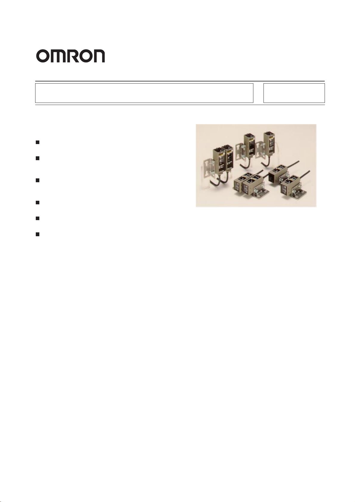
Built-in Amplifier Photoelectric Sensor
Water- and Oil-resistive Photoelectric
Sensor with Metal Housing Ensuring
Long Sensing Distance
Satisfies the requirements of IP67, NEMA 6P, and
IP67G (oil-tight).
Sensing distance six times as long as OMRON’s
conventional
detection of objects.
Ensures a vibration resistance of 10 Hz to 2 kHz
and a shock resistance of 1,000 m/s
mately 100G).
Incorporating an NPN and PNP output selector,
thus reducing the stock of photoelectric sensors.
Incorporating a fuzzy mutual interference prevention function.
The E3S-C’s optical axis coincides with its
mechanical axis, thus ensuring axis adjustment
with ease.
Photoelectric Sensors ensures
2
(approxi-
stable
E3S-C
1
Page 2
E3S-C
g
g
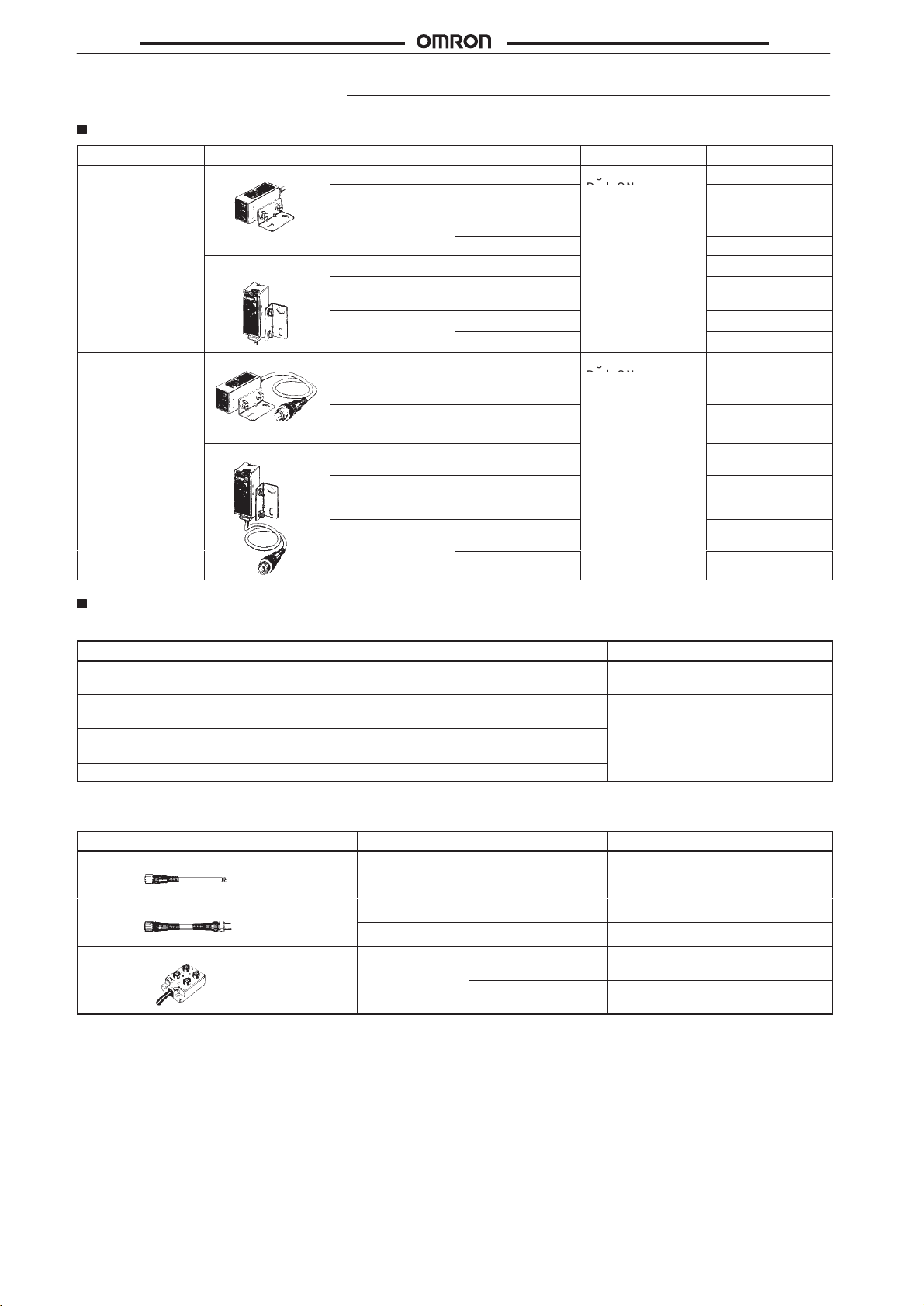
Ordering Information
E3S-C
Connections Appearance Sensing
Prewired
Junction connector
Horizontal
Vertical
Horizontal
Vertical
method
Through-beam
Retroreflective
Dif
fuse reflective
Through-beam
Retroreflective
Dif
fuse reflective
Through-beam
Retroreflective
Dif
fuse reflective
Through-beam
Sensing distance
30 m
3 m (polarized red
light source)
70 cm
2 m
30 m
3 m (polarized red
light source)
70 cm
2 m
30 m
3 m (MSR polarized
red light source)
70 cm
2 m
30 m
Operating mode
Light-ON
Dark-ON
(selectable)
Light-ON
Dark-ON
(selectable)
E3S-C
Model
E3S-CT11
E3S-CR11
E3S-CD11
E3S-CD12
E3S-CT61
E3S-CR61
E3S-CD61
E3S-CD62
E3S-CT11-M1J
E3S-CR11-M1J
E3S-CD11-M1J
E3S-CD12-M1J
E3S-CT61-M1J
Retroreflective
Dif
fuse reflective
Accessories (Order Separately)
For
E3S-C
Name Model Remarks
Slit
for Through-beam Sensor
V
ertical Mounting Bracket for the E3S-
adjustment of the Photoelectric Sensor’s optical axis direction (see note)
V
ertical Mounting Bracket for the E3S-
Photoelectric Sensor’s optical axis direction (see note)
Special Mounting Bracket
Note:
Refer to page 17 for the optical axis direction of each model.
I/O Connector
Appearance Cord Model
Single-mold
Single-mold Connector on each end
Connector Junction Box
Connector on one end only
jjjj
42 or E3S
jjjj
43 for adjustment of the
2 m
5 m
2 m
5 m
5 m
jjjj
44 for
3 m (MSR polarized
red light source)
70 cm
2 m
E39-S61
E39-L85
E39-L86
E39-L87
3-wired XS2F-D421-DC0-A
3-wired XS2F-D421-GC0-A
4-wired XS2W-D421-D81-A
4-wired XS2W-D421-G81-A
4-point input (NPN)
A set consisting of a 0.5-mm, 1-mm,
2-mm, and 4-mm slits.
Replaces the E3S with the E3S-C
Series.
XW3A-P445-G11
E3S-CR61-M1J
E3S-CD61-M1J
E3S-CD62-M1J
4-point input (PNP)
2
XW3A-P443-G11
Page 3

E3S-C
Specifications
Prewired Models
Item Through-beam Retroreflective Diffuse
E3S-CT11
E3S-CT61
LED for emitter
Sensitivity adjustment
Connection method
Weight
Output configuration
Control output Light ON or Dark ON (selectable)
Circuit protection
Indicator Emitter:
Materials Case: Zinc die-cast
Attachments
Infrared LED (880 nm)
One-turn adjustor
Prewired
Horizontal model:110 g (with 2-mm cord)
V
ertical model:115 g (with 2-mm cord)
NPN or PNP (selectable) open collector current output
Load short-circuit protection, reversed connection protection, and mutual interference prevention function
(except for through-beam models)
Emission indicator (red)
Receiver:
Stability indicator (green),
light indicator (red)
Operation panel:
Lens: Acrylic
Mounting bracket:
Mounting bracket, screw driver for adjustment, M4 hexagonal bolts, instruction sheet, and reflector
(E39-R1: retroreflective model only)
Sulfonated polyether
Stainless
E3S-CR11
E3S-CR61
Red LED (700 nm)
Stability indicator (green), light indicator (red)
E3S-CD11
E3S-CD61
Infrared LED (880 nm)
T
wo-turn endless adjustor with an indicator
E3S-C
reflective
E3S-CD12
E3S-CD62
Junction Connector Models
Item Through-beam Retroreflective Diffuse
E3S-CT11-M1J
E3S-CT61-M1J
LED for emitter
Sensitivity adjustment
Connection method
Weight
Output configuration
Control output Light ON or Dark ON (selectable)
Circuit protection
Indicator Emitter:
Materials Case: Zinc die-cast
Attachments
Infrared LED (880 nm)
One-turn adjustor
M12 metal junction connector (cord length: 30 cm)
Approx. 80 g (with 30-cm cord and connector)
NPN or PNP (selectable) open collector current output
Load short-circuit protection, reversed connection protection, and mutual interference prevention function
(except for through-beam models)
Emission indicator (red)
Receiver:
Stability indicator (green),
light indicator (red)
Operation panel:
Lens: Acrylic
Mounting bracket:
Mounting bracket, screw driver for adjustment, M4 hexagonal bolts, instruction sheet, and reflector
(E39-R1: retroreflective model only)
Sulfonated polyether
Stainless
E3S-CR11-M1J
E3S-CR61-M1J
Red LED (700 nm)
Stability indicator (green), light indicator (red)
E3S-CD11-M1J
E3S-CD61-M1J
Infrared LED (880 nm)
T
wo-turn endless adjustor with an indicator
reflective
E3S-CD12-M1J
E3S-CD62-M1J
3
Page 4
E3S-C
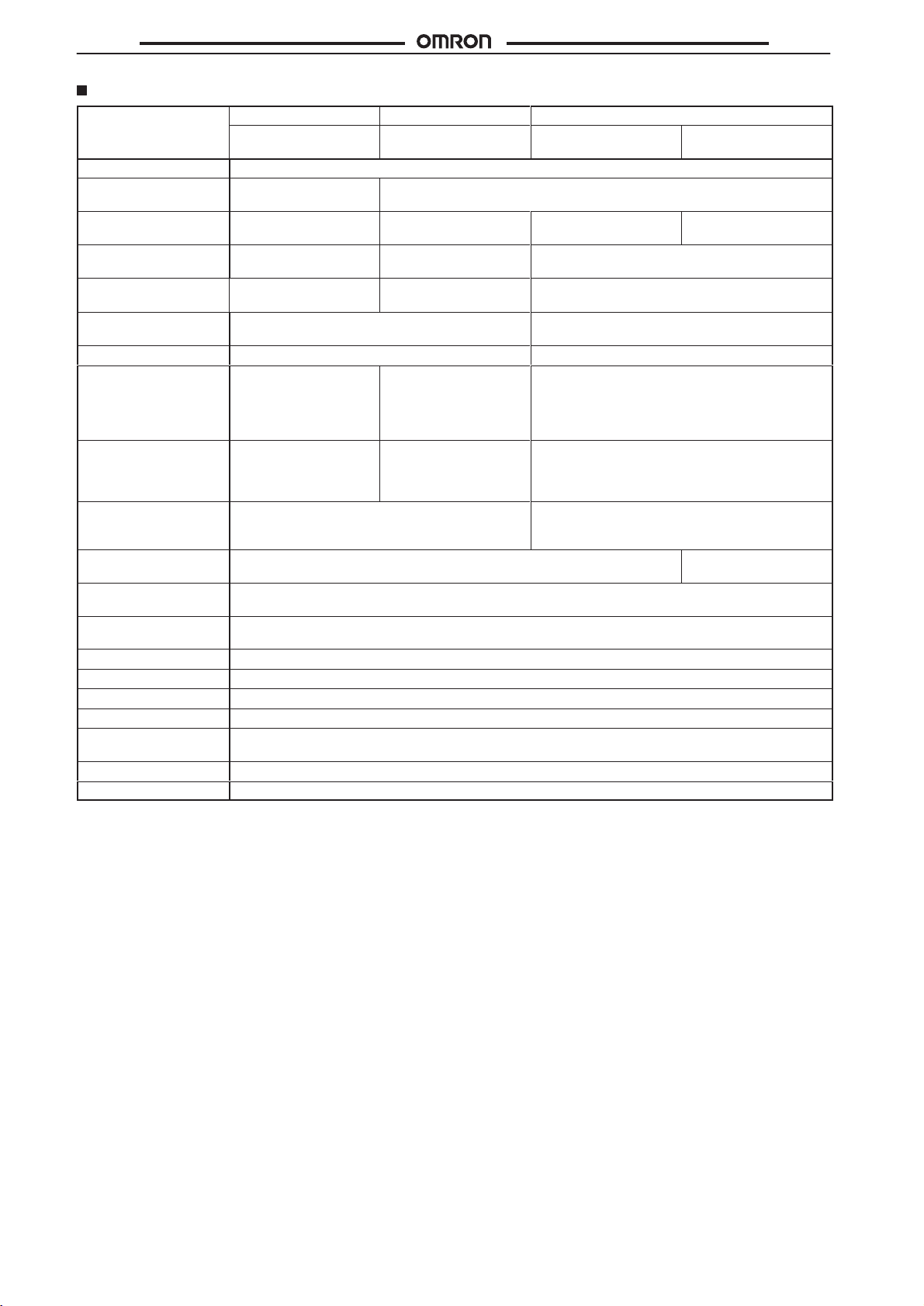
Ratings/Characteristics
Item Through-beam Retroreflective Diffuse
E3S-CT11(-M1J)
E3S-CT61(-M1J)
Power supply voltage
Current consumption
Sensing distance
(white paper)
Standard sensing
object
Directional angle
V
ariation in sensing
distance
Hysteresis --Sensing distance with
attachment
Min. sensing object
(see note)
Difference in direction
between optical axis
and mounting direction
Response time
Control output
Ambient illumination
Ambient temperature
Ambient humidity
Insulation resistance
Dielectric strength
V
ibration resistance
Shock resistance
Enclosure ratings
*NEMA:
National Electrical Manufactures Association
**JEM:
Japan Electrical Manufacturers
Note:
At the rated sensing distance, set a sensing object at half the rated sensing distance.
10 to 30 VDC (including ripple (p–p) 10%)
50 mA max. (emitter and
receiver)
0 to 30 m 0 to 3 m
---
3°
to 15
° Sensor: 3°
---
4-mm slit:
2-mm slit:
1-mm slit:
0.5-mm slit:
4-mm slit:
2-mm slit:
1-mm slit:
0.5-mm slit:
±2°
max. (checked along extended line in the
mounting direction)
1 ms max. for both operation and release
30 VDC, 100 mA max. (residual voltage: NPN output: 1.2 V max., PNP output: 2.0 V max.), open collector
(NPN/PNP output selectable)
Incandescent lamp:
Sunlight:
Operating: –25°C to 55°C (with no icing)
Operating: 35% to 85%
20 MΩ min. (at 500 VDC)
1,000 V
Destruction: 10 to 2,000 Hz, 1.5-mm double amplitude, or 300 m/s2 (approx. 30G) 0.5 hrs each in X, Y
Z directions
Destruction: 1,000 m/s2 (approx. 100G) 3 times each in X, Y
IEC: IP67, NEMA*: 6P (indoors only), JEM**: IP67G
15 m
7 m
3.5 m
1.8 m
2.6-mm dia.
2-mm dia.
1-mm dia.
0.5-mm dia.
illumination on optical spot:
illumination on optical spot:
AC, 50/60 Hz for 1 min
E3S-CR11(-M1J)
E3S-CR61(-M1J)
40 mA max.
With the E39-R1
Reflector: 30°
E39-R2:
E39-R3:
E39-R4:
E39-RSA:
E39-RSB:
E39-R1 Reflector:
13-mm dia.
E39-R3:
E39-R4:
to 10
min.
0 to 4 m
0 to 150 cm
0 to 75 cm
5 to 35 cm
5 to 60 cm
8-mm dia.
4-mm dia.
°
E3S-CD11(-M1J)
E3S-CD61(-M1J)
0 to 70 cm
30 x 30 cm (white paper)
---
±
10% max.
20% max. of sensing distance
---
---
±2°
max.
5,000
ȏx max.
10,000
ȏx max.
, and Z directions
E3S-C
reflective
E3S-CD12(-M1J)
E3S-CD62(-M1J)
0 to 2 m
2 ms max. for both
operation and release
, and
4
Page 5
E3S-C
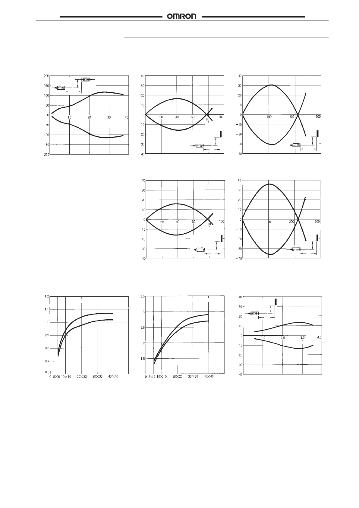
Engineering Data
E3S-C
Parallel Operating Range
(Typical)
E3S-CTj1
Y
Y (cm)
Parallel operating range
X
Set distance
X (m)
Operating Range (Typical)
E3S-CDj1
(mm)
Y
Operating position
E3S-CDj1 (Up and Down) E3S-CDj2 (Up and Down)
(mm)
Y
Operating position
(Left and Right)
Set
distance
X (cm)
Sensing
object
Y
X
Set distance
X (cm)
Sensing
object
Y
X
E3S-CDj
(mm)
Y
2 (Left and Right)
Operating position
(mm)
Y
Operating position
Set distance
X (cm)
Sensing
object
Y
X
Set distance
X (cm)
Sensing
object
Y
X
Sensing Distance vs.
Object Size (Typical)
E3S-CDj1
Sensing object: White paper
Sensing distance (m)
Size of object (cm)
OFF
ON
E3S-CDj2
Sensing object: White paper
Sensing distance (m)
Size
of object (cm)
OFF
ON
Reflector Parallel
Movement (Typical)
E3S-CRj1
E39-R1
Reflector
Y (cm)
Parallel operating range
Y
X
Set distance X (m)
5
Page 6
E3S-C
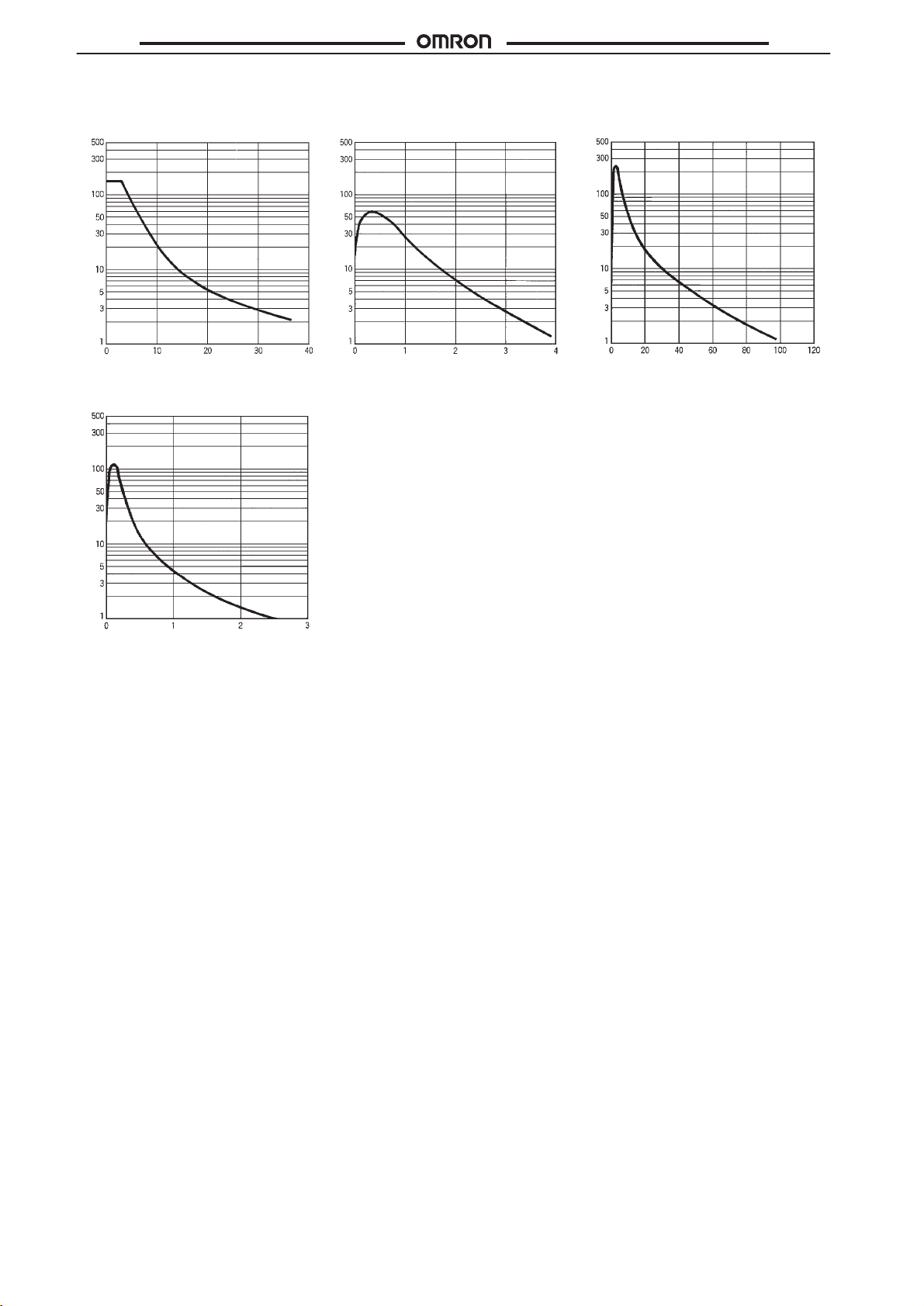
Excess Gain vs. Set Distance (Typical)
E3S-CTj1
E3S-CRj1
(E39-R1 Reflector)
E3S-C
E3S-CDj1
Excess gain ratio
E3S-CDj2
Excess gain ratio
Excess gain ratio
Distance (m) Distance (m) Distance (cm)
Distance (m)
Excess gain ratio
6
Page 7
E3S-C
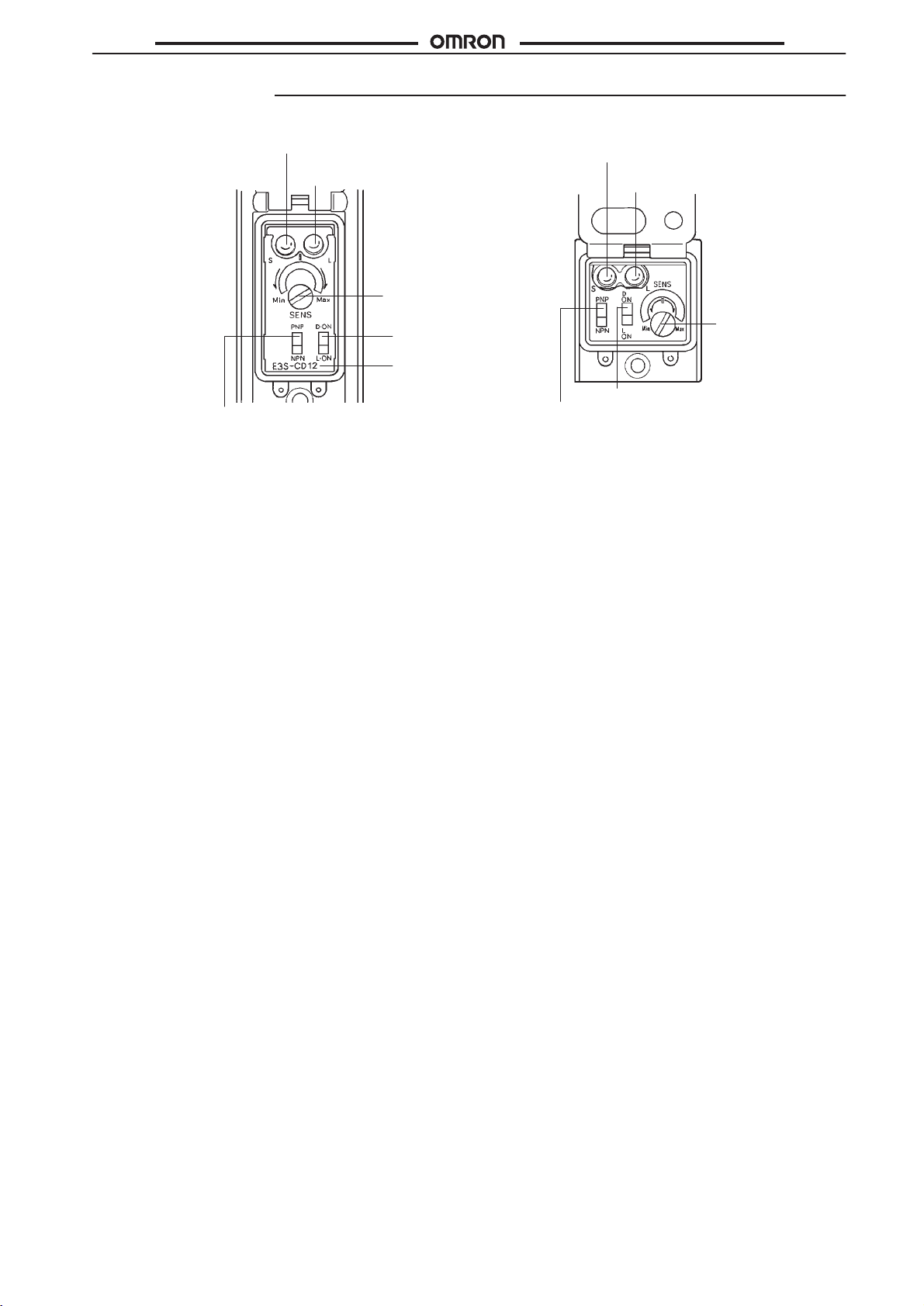
Nomenclature
E3S-C
Horizontal Model Vertical Model
Stability
NPN and PNP
output selector
indicator (green)
Light indicator
(red)
Stability indicator (green)
Light indicator
(red)
Sensitivity
adjuster
L-ON and D-ON
selector
Model
number
L-ON and D-ON selector
NPN and PNP output
selector
Operation Panel
Use
the NPN and PNP output selector on the operation panel to select the type of output transistor
Use the Light ON and Dark ON selector on the operation panel to select the operation mode of the E3S-C.
.
Sensitivity
adjuster
7
Page 8
E3S-C
NPN
PNP
Photoelectric
Photoelectric
NPN and PNP
Black
C
Operation
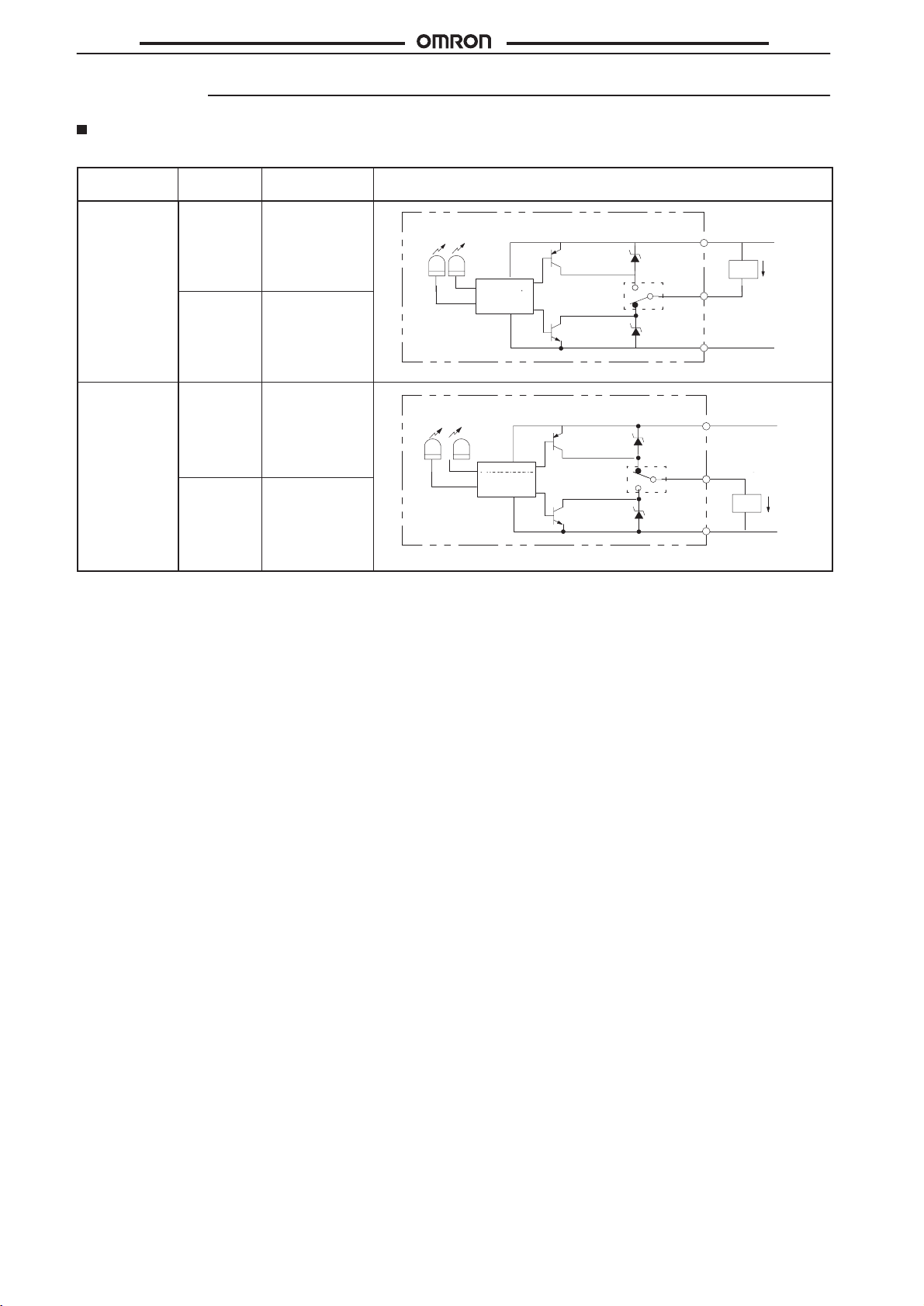
Output Circuits
Prewired Models
Output
configuration
NPN
PNP Light ON
Mode
switch
Light ON
Dark ON
Dark ON
Output
transistor
On when light is
received.
ON when light is
not received.
On when light is
received.
ON when light is
not received.
Light
indicator
(Red)
ZD : Vz = 39 V
Light
indicator
(Red)
ZD : Vz = 39 V
Stability
indicator
(Green)
Photoelectric
sensor main
circuit
Stability
indicator
(Green)
Photoelectric
sensor main
circuit
Output
PNP output
transistor
and
output selector
NPN output
transistor
PNP output
transistor
NPN and PNP
output selector
NPN output
transistor
circuits
ZD
ZD
ZD
ZD
Set the NPN
and PNP
output selector to NPN.
Set the NPN
and PNP
output selector to PNP.
Brown
Black
Blue
Brown
Black
Blue
10 to 30 VDC
Load
Control
output
10 to 30 VDC
Control
output
Load
E3S-C
Load
current
0 V
Load
current
0 V
8
Page 9
E3S-C
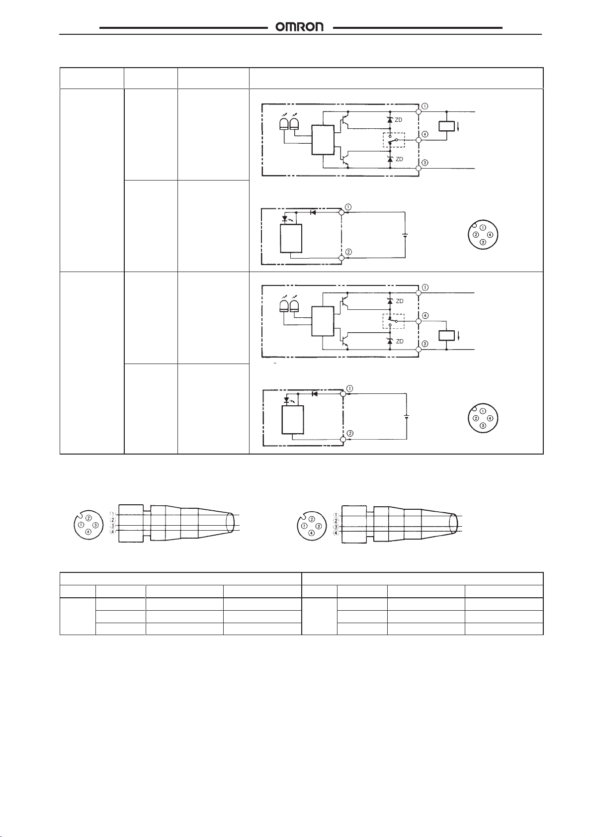
Junction Connector Models
Output
configuration
NPN
Mode
switch
Light ON
Dark ON
On when light is
received.
ON when light is
not received.
Output
transistor
Reflective T
Light
indicator
(Red)
: VZ = 39 V
ZD
Emitter
Emitter
indicator
(red)
Photoelectric
sensor
main
circuit
ype and Receiver
Stability
indicator
Photo-
(Green)
electric
NPN and PNP
sensor
output selector
main
circuit
Note: Set
the NPN and PNP output selector to NPN
Output
PNP output
transistor
NPN output
transistor
circuits
(See
note)
10 to 30 VDC
10 to 30 VDC
Load
Control output
Load
current
0 V
.
Connector
Arrangement
Pin
E3S-C
PNP Light ON
Dark ON
I/O
Connector Plug
On when light is
received.
ON when light is
not received.
Reflective T
Light
indicator
(Red)
: VZ = 39 V
ZD
Emitter
Emitter
indicator
(red)
ype and Receiver
Stability
indicator
Photo-
(Green)
electric
sensor
main
circuit
Note: Set
Photoelectric
sensor
main
circuit
NPN Output PNP Output
Terminal
no.
XS2F-D421-DC0–A
XS2F-D421-GC0–A
Brown
Blue
Black
Terminal no.
10 to 30 VDC
PNP output
transistor
p
10 to 30 VDC
Control output
Load
Load
current
0 V
Connector
Arrangement
Brown
Blue
Black
NPN and PNP
output selector
NPN output
transistor
(See
note)
the NPN and PNP output selector to NPN
XS2F-D421-DC0–A
XS2F-D421-G81–A
.
Pin
PNP output
Connector pin
Application
Type Conductor
NPN output
Connector pin
Application Type Conductor
DC Brown 1 Power supply (+V) DC Brown 1 Power supply (+V)
Black 4 Output Black 4 Output
Blue 3 Power supply (0 V) Blue 3 Power supply (0 V)
9
Page 10
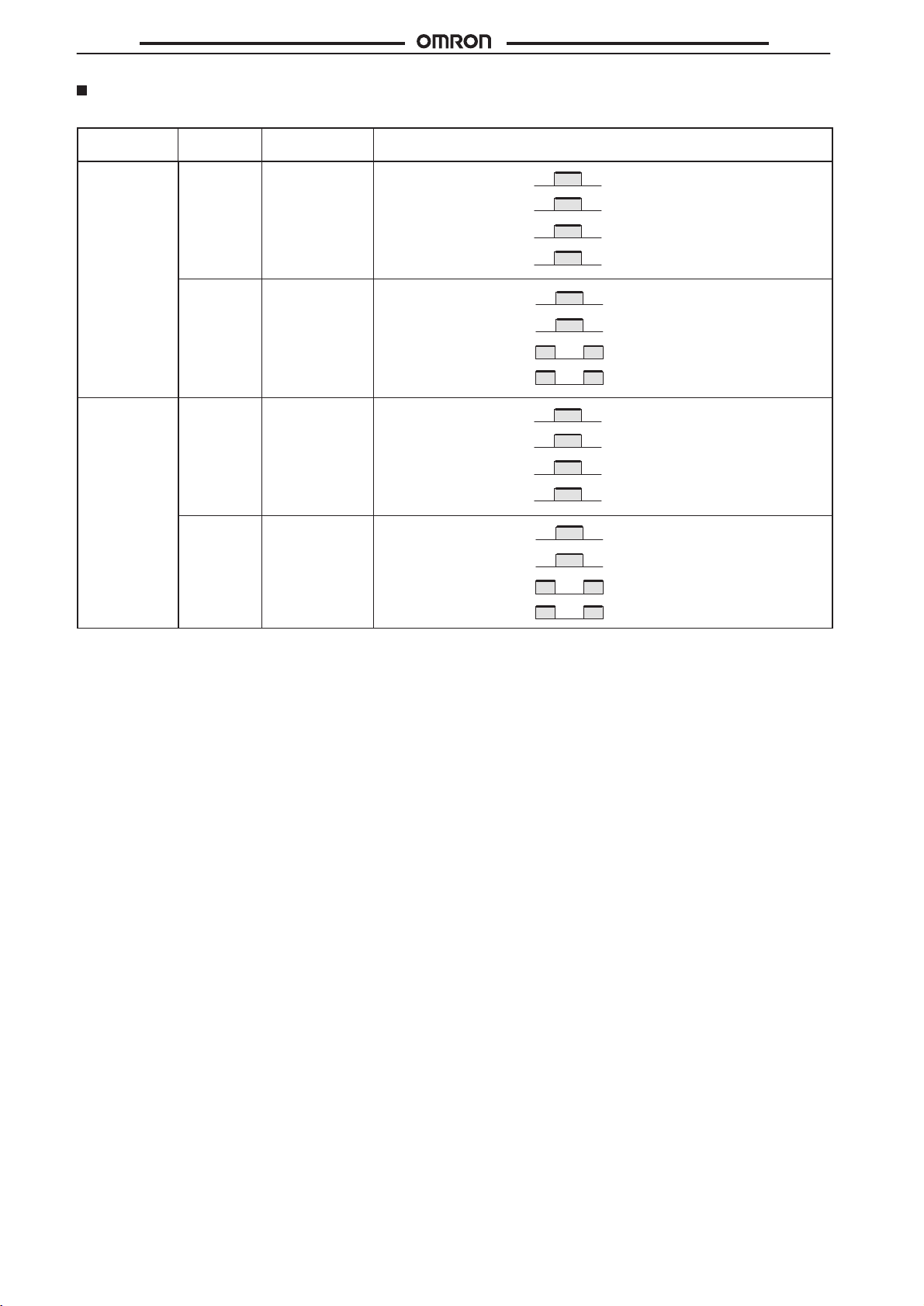
E3S-C
Timing Chart
Prewired
Output
configuration
NPN
PNP Light ON
Mode
switch
Light ON
Dark ON
Dark ON
Output
transistor
On when light is
received.
ON when light is
not received.
On when light is
received.
ON when light is
not received.
Light received
Light not received
Light indicator
(Red)
Output
transistor
Load
(relay)
Light received
Light not received
Light indicator
(Red)
Output
transistor
Load
(relay)
Light received
Light not received
Light indicator
(Red)
Output
transistor
Load
(relay)
Light received
Light not received
Light indicator
(Red)
Output
transistor
Load
(relay)
Operate
Release
Operate
Release
Operate
Release
Operate
Release
ON
OFF
ON
OFF
ON
OFF
ON
OFF
ON
OFF
ON
OFF
ON
OFF
ON
OFF
Timing
E3S-C
chart
(Between brown and black)
(Between brown and black)
(Between blue and black)
(Between blue and black)
10
Page 11
E3S-C
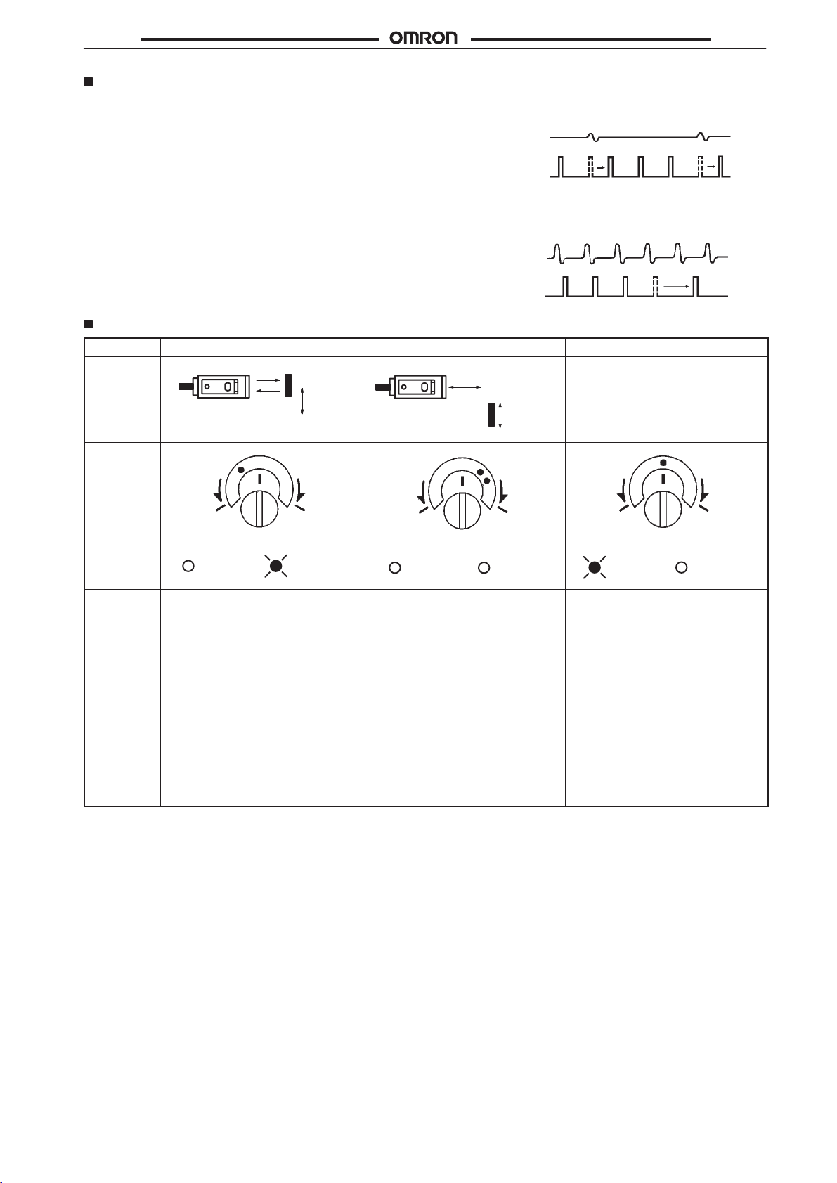
Fuzzy Mutual Interference Prevention Function
If reflective Photoelectric Sensors are installed side by side, each
reflective Photoelectric Sensor may be influenced by the light
emitted
from the other Photoelectric Sensors.
The
fuzzy mutual interference prevention function of the E3S-C en
ables
the E3S-C to monitor any light interference for a certain period
before
the E3S-C starts emitting light so that the E3S-C can retrieve
the
intensity and frequency of the light interference as data. Using
this data, the E3S-C estimates with fuzzy inference the risk of the
malfunctioning
emission.
light
of the E3S-C and controls the timing of the E3S-C’
When the risk is low:
The
-
s
When
The E3S-C emits light between each light interference moment.
Sensitivity Adjustment (Reflective Sensors)
Item Position A
Sensing
condition
Photoelectric sensor
Position B
Photoelectric sensor
E3S-C
E3S-C waits until there is no light interference and emits light.
Light interference
Emission pattern
the risk is high:
Light interference
Emission pattern
Setting
---
Sensitivity
adjustor
Indicators
OFF ON
Procedure Locate
sensing distance, set the sensitivity
adjustor to the minimum scale
position, and gradually increase
sensitivity by turning the sensitivity
adjustor clockwise until the incident
light indicator (red LED) is ON.
Position A is where the indicator has
turned ON. Regard the maximum
scale position as Position A if the
indicator does not turned ON at full
sensitivity.
A
Min. Max.
STABILITY
(green)
a sensing object at the
Sensing object
LIGHT
(red)
Min. Max.
OFF OFF
STABILITY
(green)
Remove the sensing object and turn
the sensitivity adjustor clockwise until
the E3S-C detects the background
object and the incident light indicator
(red LED) is lit. The moment the red
light indicator is lit, stop turning the
sensitivity adjustor
which is point B. T
, the position of
urn the sensitivity
adjustor counterclockwise to decrease
the sensitivity until the red light
indicator is OFF
. The moment the red
light indicator is OFF
sensitivity adjustor
, the position of
Sensing object
C
B
LIGHT
(red)
, stop turning the
AC
Min. Max.
OFF ON
STABILITY
(green)
Set the sensitivity indicator to the
position between Positions A and C
(in some cases, Positions A and C are
opposite of the above example). The
photoelectric sensor will then work
normally if the stability indicator
(green) is lit with and without the
sensing object. If it is not lit, stable
operation cannot be expected, in
which case a dif
ferent sensing
method must be applied.
which is point C.
If there is no background object, point
C is where the sensitivity adjustor is
set to maximum.
Unlike
conventional photoelectric sensors, the variation in the sensitivity of E3S photoelectric sensors is minimal. This means the sensitivity
can
be adjusted on only a single photoelectric sensor
position.
There is no need to adjust the sensitivity of each photoelectric sensor individually
, and
then the adjustors on the other photoelectric sensors can be set to the same scale
.
LIGHT
(red)
11
Page 12
E3S-C
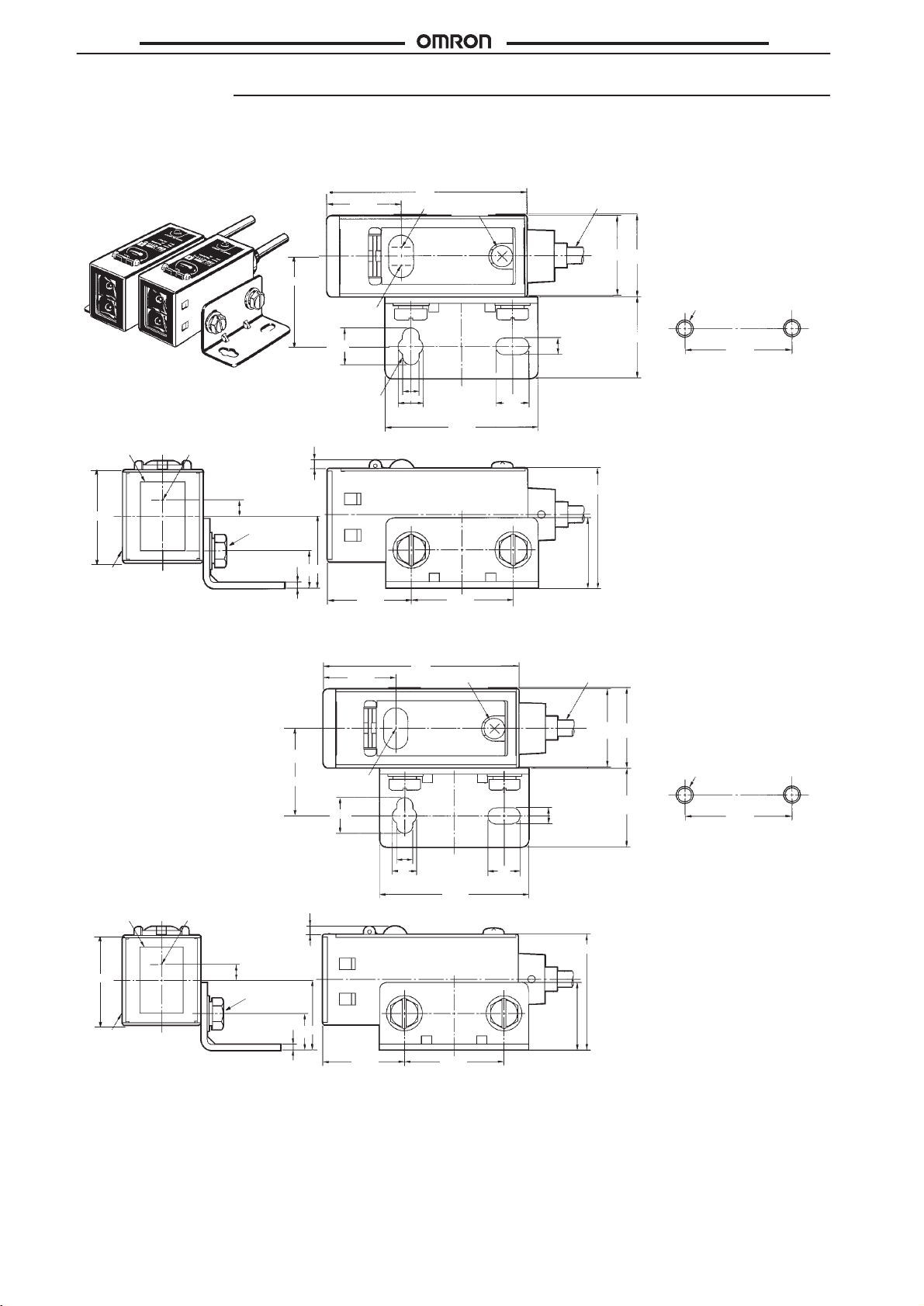
Dimensions
Note:
All units are in millimeters unless otherwise indicated.
E3S-C
E3S-CT11 (Receiver)
22
Stability indicator
(green)
9.2
18.5
50
Light indicator (red)
M3 x 5
Vinyl-insulated cord with three conductors,
4 dia. (18 x 0.12 dia.); standard length: 2 m
20
20.4
Mounting
Two, M4
4.2
20
E3S-C
Holes
25.4
Lens (17 x 11) Optical axis
23
*
A
*The mounting bracket can
be attached to side A.
E3S-CT11 (Emitter)
Two mounting holes
4
Two, M4
1.5
22.2
Emission indicator (red)
4.2
6.2
38.2
2.2
18
9.3
20.8 25.4
18.5
9.2
50
M3 x 5
8.3
29.5
17.3
Vinyl-insulated cord with two conductors, 4 dia.
(27 x 0.12 dia.); standard length: 2 m
20
20.4
4.2
20
Mounting
Two, M4
Holes
25.4
23
A
*
*The mounting bracket can
be attached to side A.
12
4.2
6.2
Optical axisLens (17 x 11)
2.2
4
Two, M4
1.5
18
9.3
20.8 25.4
38.2
8.3
29.5
17.3
Page 13
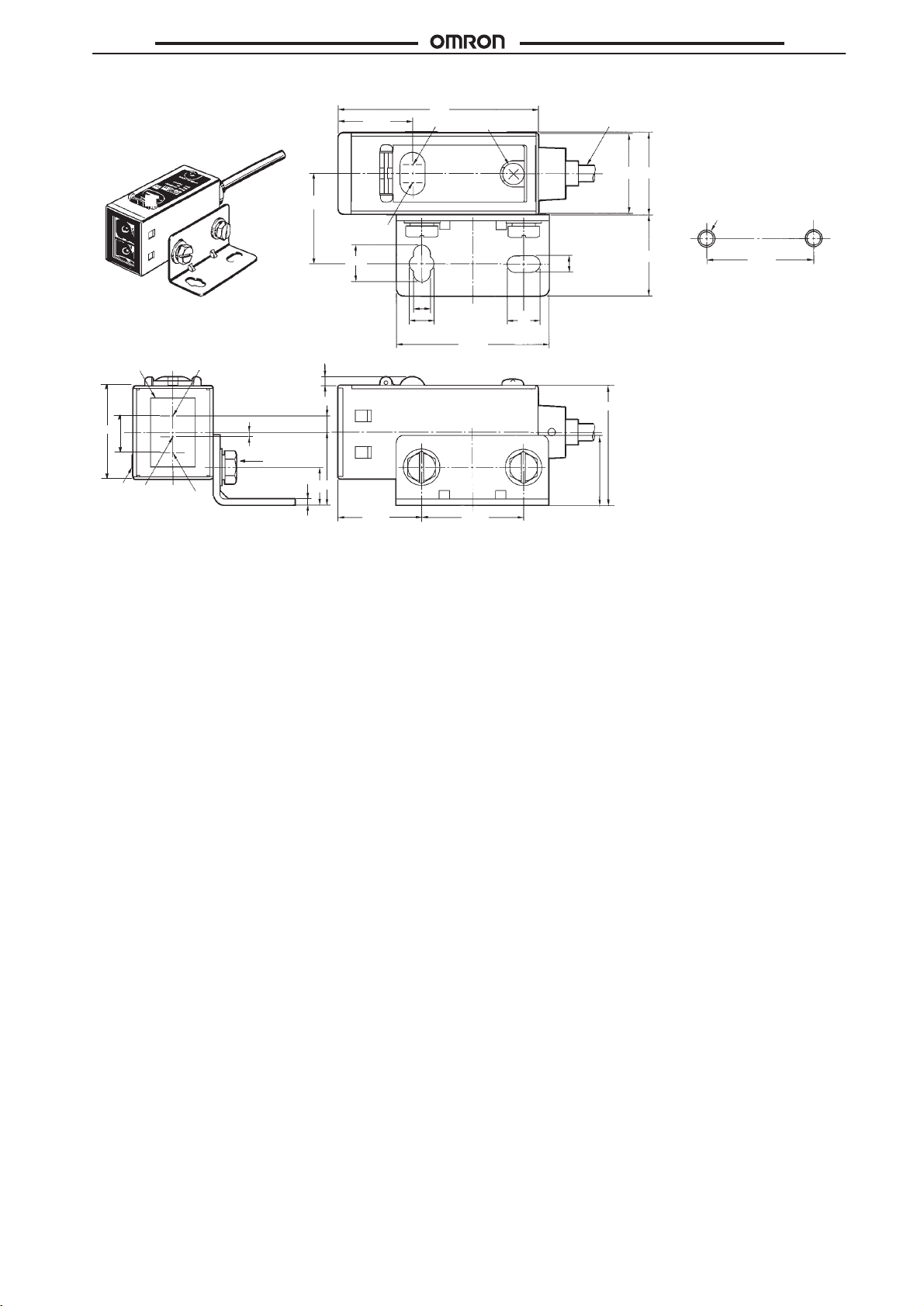
E3S-C
E3S-CR11
E3S-CD11
E3S-CD12
22.2
Stability indicator
(green)
9.2
18.5
50
Light indicator (red)
M3 x 5
Vinyl-insulated cord with three conductors,
4 dia. (18 x 0.12 dia.); standard length: 2 m
20
20.4
Mounting
Two, M4
4.2
20
E3S-C
Holes
25.4
(17 x 1
A
*
Optical axis
1)
Receiver
Emitter
Lens
23
9
*The mounting bracket can
be attached to side A.
4.2
6.2
38.2
2.2
4
1
Two, M4
1.5
18
9.3
20.8
25.4
8.3
29.5
17.8
13
Page 14
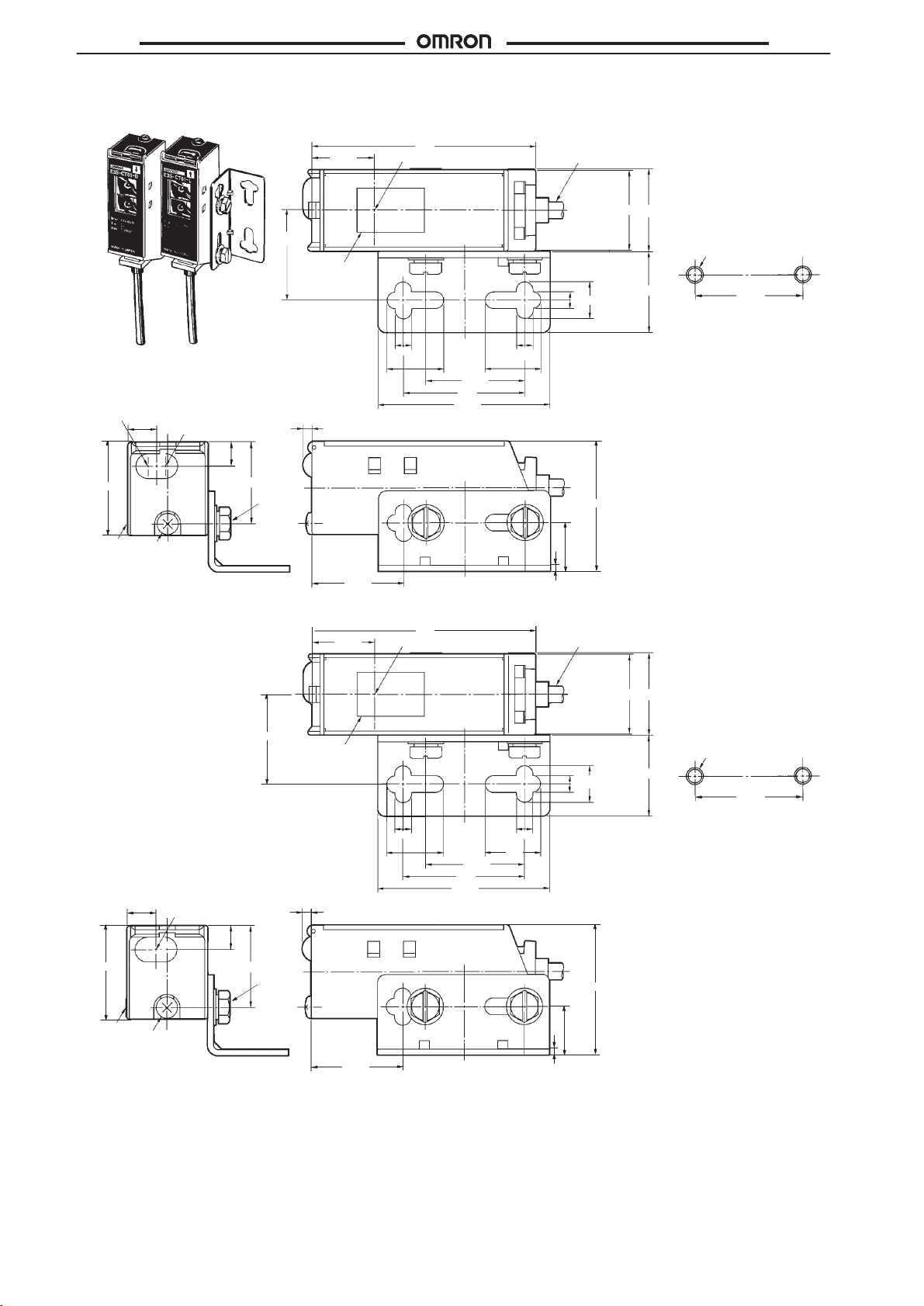
E3S-C
E3S-CT61 (Receiver)
E3S-C
Stability indicator
(green)
23
*
A
*The mounting bracket can
be attached to side A.
7.2
M3 x 5
Light indicator
(red)
5.8
20.2
22.2
Two, M4
15.8
Lens (17 x 11)
2.2
23.2
Optical axis
4.2
14.4
57
14.4
25.4
31
43.8
Vinyl-insulated cord with three conductors,
4 dia. (18 x 0.12 dia.); standard length: 2 m
20
20.4
9.2
4.2
4.2
32.2
12
1.5
20
Mounting
Two, M4
Holes
25.4
E3S-CT61 (Emitter)
7.2
Emission indicator (red)
23
*
A
M3 x 5
*The mounting bracket can
be attached to side A.
5.8
20.2
22
Two, M4
15.8
Lens (17 x 11)
2.2
23.2
57
Optical axis
4.2
14.4
31
43.8
25.4
Vinyl-insulated round cord with two conductors,
4 dia. (27 x 0.12 dia.); standard length: 2 m
20.420
12
9.2
4.2
4.2
32.2
12
1.5
20
Mounting
Two, M4
Holes
25.4
14
Page 15
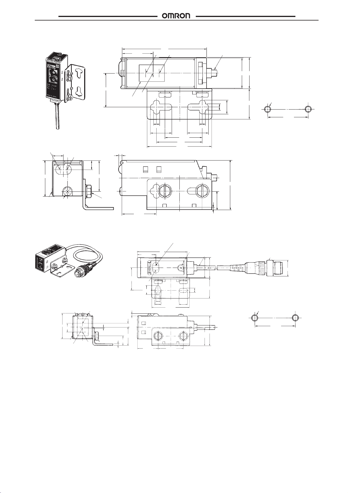
E3S-C
E3S-CR61
E3S-CD61
E3S-CD62
20.8
57 Vinyl-insulated cord with three conductors,
Receiver
Emitter
4 dia. (18 x 0.12 dia.); standard length: 2 m
20.4
20
E3S-C
Stability indicator
(green)
23
A*
*The mounting bracket can
be attached to side A.
7.2
M3 x 5
Light indicator
(red)
E3S-Cj1j-M1J
(Horizontal)
5.8
20.2
22
Lens (17 x 11)
Two, M4
2.2
Optical
axis
23.2
18.5
4.2
14.4
50
25.4
31
43.8
Light indicator
(red) (see note 2)
M3 ×
4.2
9.2
4.2
14.4
32.2
12
1.5
Vinyl-insulated cord with three
conductors, 4 dia. (18 x 0.12 dia.);
5
standard length: 0.3 m (see note 3)
Mounting
20
Two, M4
M12 ×
Holes
25.4
1
Lens
23
A (see note 1)
Optical axis
Note: 1. The
22.2
Stability
indicator
(17 x 1
9
1)
Emitter
Receiver
(see note 4)
1
Two, M4
1.5
9.3
2.2
(green)
9.2
4.2
6.2
38.2
4
18
20.8 25.4
4.2
8.3
17.3
mounting bracket can be attached to side A.
2.
The emitter for through-beam sensors have only the power supply indicator
3. The
cord for emitters for through-beam sensors is
4. Position
of optical axis for through-beam sensors.
two-conductor
20
29.5
.
, 4 dia. (27 x 12 dia.).
Mounting
Two, M4
16 dia.
Holes
25.4
15
Page 16
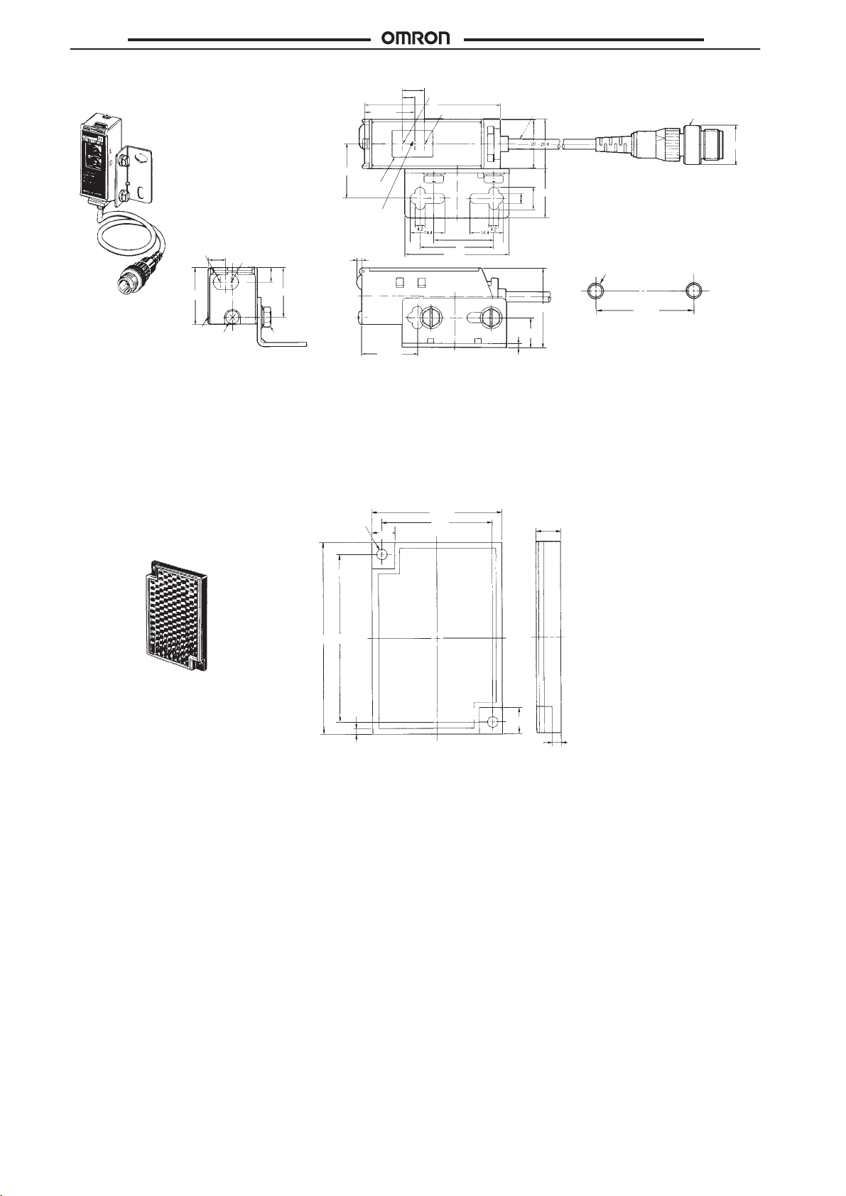
E3S-C
E3S-C
E3S-Cj6j-M1J
(Vertical)
Stability
indicator
(green)
A
(see note 1)
Note: 1.
The mounting bracket can be attached to side A.
2.
The emitter for through-beam sensors have only the power supply indicator
3. The
4. Position
Attachments
E39-R1 Retroreflector
(Retroreflective
the E3S-CR1
type, provided with
1(-M1J)/CR61(-M1J))
20.8
22.2
Lens
(17
x 1
1)
Optical
axis
Light indicator
7.2
(red) (see note 2)
5.8
23
M3 ×
20.2
Two, M4
5
2.2
23.2
cord for emitters for through-beam sensors is
of optical axis for through-beam sensors.
Two, 3.5 dia.
7
9
5
Receiver
(see note 4)
57
Emitter
25.4
31
43.8
two-conductor
40.3
34
Vinyl-insulated cord with three
conductors, 4 dia. (18 x 0.12 dia.);
standard length: 0.3 m (see note 3)
9.2
20
4.2
Mounting
Two, M4
32.2
12
1.5
.
, 4 dia. (27 x 12 dia.).
7.5
25.4
Holes
M12 ×
1
16 dia.
59.9
52
8
1.6
2.7
16
Page 17
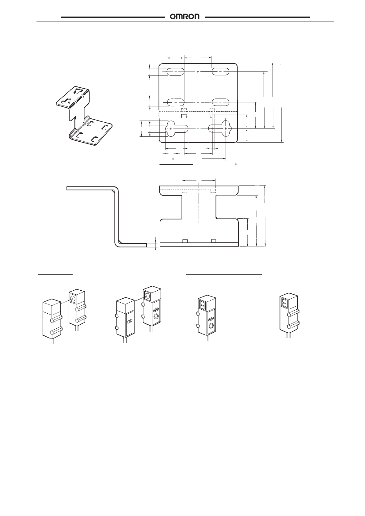
E3S-C
Accessories (Order Separately)
For Replacing the E3S Series with the E3S-C Series
E3S-C
E39-L85 Special Mounting Bracket
(Vertical/E3S-jjjj42/44
the Photoelectric Sensor’s optical axis direction)
for adjustment of
9.2
4.2
4.2
4.2
4.2
9.8
15.6
43.8
37
(44.7)
32
15
8
8
16
31
19
2.612.9
32.2
28.9
Sensing Face Direction of the E3S Series
Through-beam
E3S-5E44
Receiver
Emitter
E3S-5E42
Emitter
1.5
Receiver
15.1
Retroreflective/Diffuse Reflective
E3S-DS30E44
E3S-R2E44
E3S-DS30E42
E3S-R2E42
17
Page 18
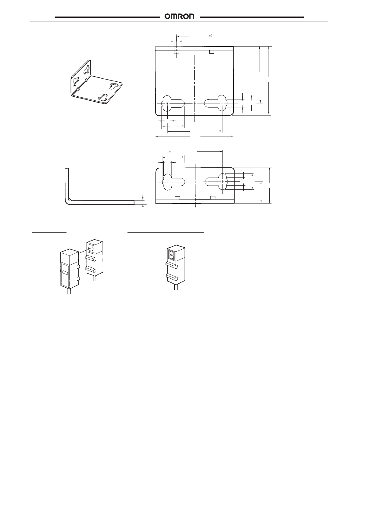
E3S-C
E3S-C
E39-L86 Special Mounting Bracket
(Vertical/E3S-jjjj43
Photoelectric Sensor’s optical axis direction)
for adjustment of the
1.5
2.6
4.2
4.2
12.9
12.9
20
43.8
31
32.2
39
4.2
9.2
31
9.2
4.2
20
12
Sensing Face Direction of the E3S Series
Through-beam
E3S-5E43
Receiver
Emitter
Retroreflective/Diffuse Reflective
E3S-DS30E43
E3S-R2E43
18
Page 19
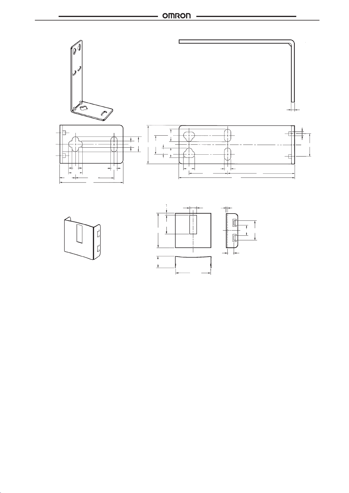
E3S-C
E39-L87 Special Mounting Bracket
4.2
E3S-C
1.5
2.6
8.2
25 12.4
10
4.1
6.2
15
4.2
9.2
10
41
E39-S61 Slit for E3S-C
25.4
4.2
6.5
7.2
25.4
See note
11
20
20.1
4.2
75.6
0.2
6.2
3.8
Note: This
or
4 mm depending on the type.
43.7
11.8
size
is 0.5 mm, 1 mm, 2 mm,
19
Page 20
E3S-C
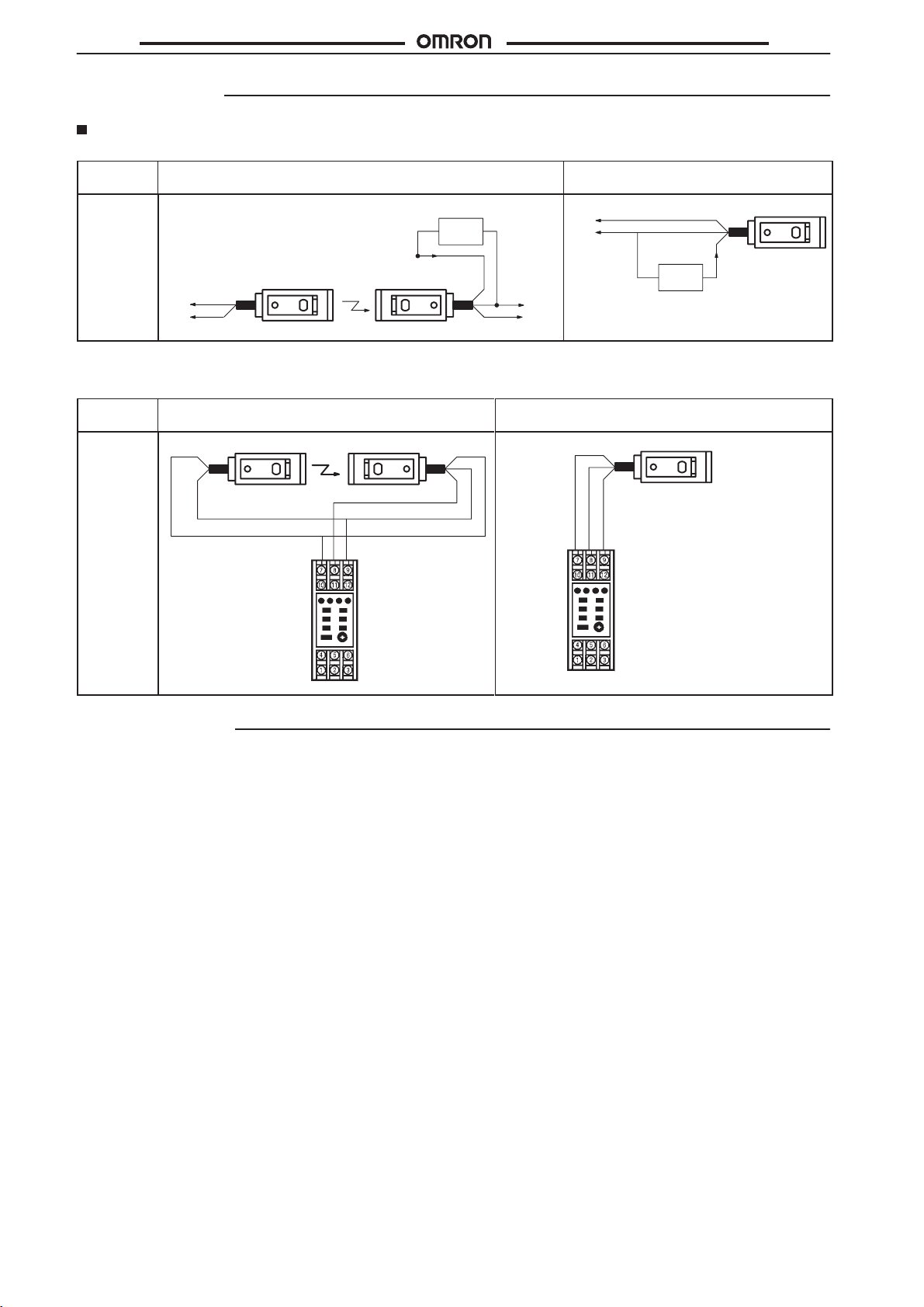
Installation
Connections
Load (Relay)
Sensing
method
Connection
method
10
to
30 V
0 V
Brown
Blue
Through-beam Retroreflective/diffuse
Blue
Brown
100 mA max.
Emitter Receiver
100 mA max.
Load
Black
Blue
Brown
10 to
30 V
0 V
0V
10 to
30 V
Load
E3S-C
reflective
Black
Output
Note: If
the load is a relay
, insert a surge absorbing diode between the coils of the relay
The connection examples are for sensors with the NPN output.
With Sensor Controller (S3D2)
Sensing
method
Connection
method
Brown
Blue
Through-beam Retroreflective/diffuse
Emitter Receiver
Black
IN1
+12 V 0 V
S3D2
Precautions
Connection
If the input/output lines of the photoelectric sensor are placed in the
same
conduit or duct as power lines or high-voltage lines, the photo
electric sensor could be induced to malfunction, or even be damaged,
by electrical noise.
lines
as input/output lines to the photoelectric sensor
cord connected to the E3S-C can be extended up to
The
vided
that the diameter of each wire of the
Either separate the wiring, or use shielded
.
100 m pro
cord is 0.3 mm2 minimum.
Startup Operation
A
maximum of 100 ms
until
the E3S-C is able to detect objects. If power is supplied to the
loads and the E3S-C from different sources, turn on power to the
first.
E3S-C
is required from the time power is turned on
-
-
.
reflective
Brown
Blue
Brown
Black
Blue
IN
1
+12 V 0 V
S3D2
Power Supply
If a standard switching regulator is used as a power supply, the
frame ground (FG) terminal and the ground (G) terminal must be
grounded, or otherwise the E3S-C may malfunction, due to the
switching
noise of the power supply
.
Water Resistivity
Do
not use the E3S-C in water
To ensure the water resistivity of the E3S-C, tighten the screws of
the
operation panel cover to a torque of 3.5 to 5.5 kgf S cm (0.34 N
m
to 0.54 N S m).
, in the rain, or outdoors.
S
20
Page 21
E3S-C
g
g
Oil and Chemical Resistivity
Do
not use the E3S-C in oils or liquid chemicals.
Although the E3S-C is oil-resistive, refer to the following table before using the E3S-C in places where oil may be sprayed on the
E3S-C.
Tests
were carried out with the following oils and it
the E3S-C resists these oils.
Oil
Lubricating oil
W
ater insoluble machining oil
W
ater soluble machining oil
Note: 1. The
E3S-C maintained a minimum insulation resistance of 100 MΩ after the
of
50°C for 240 hours.
2. When
3.
using the E3S-C in a place where an oil other than the ones listed above is sprayed on
viscosity
above
ence
JIS: Japan Industrial Standards
and ph values. The location may
kinematic viscosity and pH values, but make sure that
on the E3S-C.
--- V
No. 5, type 2
No. 1
No. 1, type W1
No. 2, type W1
No. 1, type W2
JIS classification
1, type 2
was certified that
be suitable for the E3S-C if the kinematic viscosity and pH values of the oil are close to the
Product name
elocite No.3
Daphnecut
Y
ushiron Oil No. 2 ac
Y
ushiroken EC50T
Y
ushiron Lubic HWC68
Griton 1700D
Y
ushiroken S50N
the oil does not contain any additive that may have a negative influ
-3 ---
E3S-C was dipped in all the above oils at a temperature
Kinematic viscosity
(mm2/s (cst)) at 40
2.02 --10 min. and less than 50
Less than 10
the E3S-C, refer to the above kinematic
°C
E3S-C
PH
7 to 9.5
7 to 9.9
7 to 9.2
7 to 9.8
-
Cable
The E3S-C uses an oil-resistive cord to ensure oil resistivity
Do not allow the cable to be repeatedly bent during application.
Do not allow the cable to be bent to a radius of less than 25 mm.
.
Mounting
When
mounting the E3S-C, do not hit the E3S-C with a hammer
the
E3S-C will loose watertightness.
Use M4 screws to mount the E3S-C.
The
tightening torque
maximum.
Mounting
When
ing
tical axis lock holes.
If
it is not possible
will be in the direction the mechanical axis, move the E3S-C upwards,
in
time
Bracket
mounting the E3S-C with the mounting bracket so that sens
objects will
downwards, to the left, or to the right and secure the
the center of the range where the light indicator will be
make sure that the stability indicator is lit.
of each screw must be 12 kgf S m (1.18 N S m)
be in the direction of the mechanical axis, use the op
to mount the E3S-C so that the sensing objects
, or
E3S-C
lit, at which
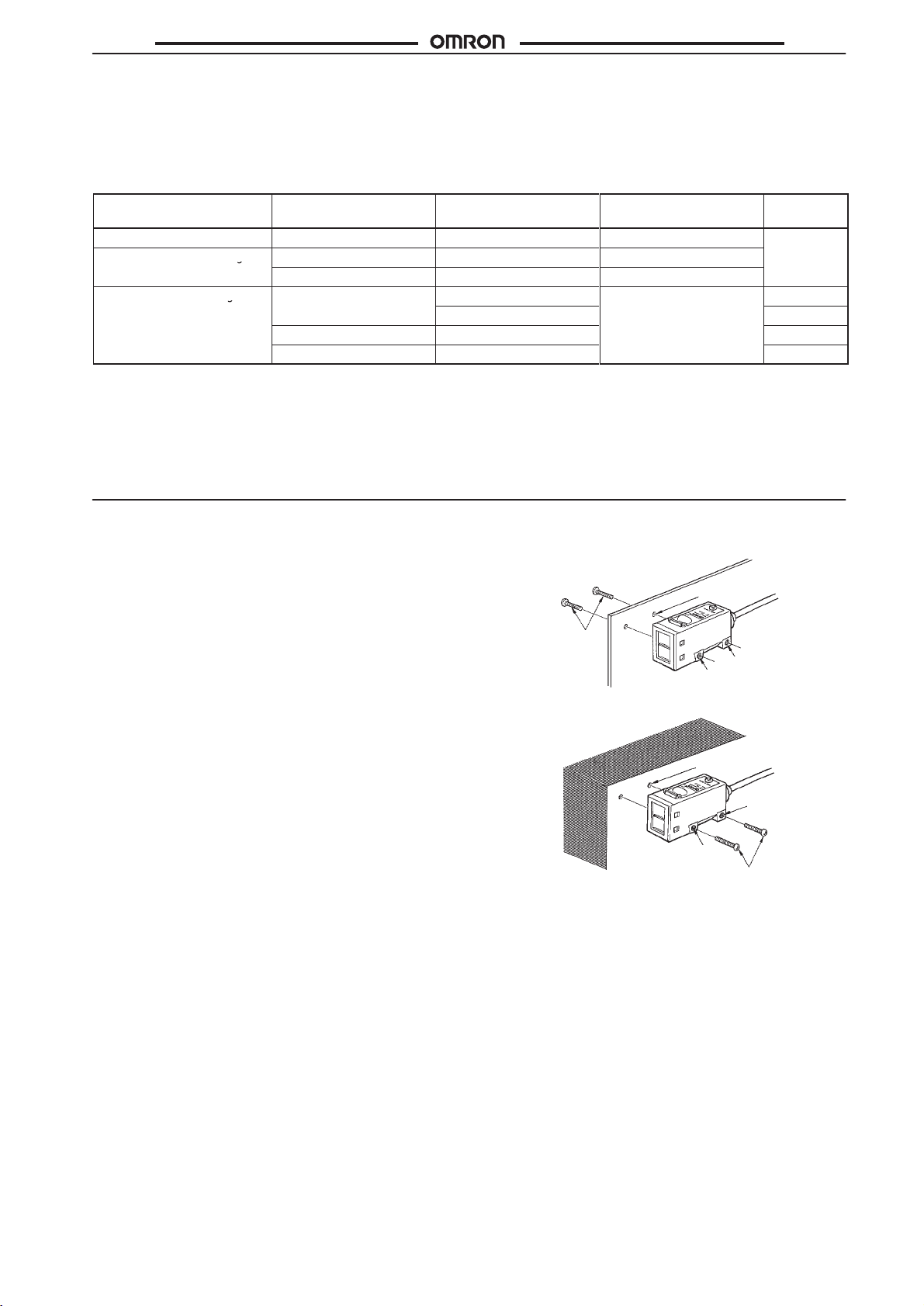
Direct Mounting
Mount the E3S-C as shown in the following illustration.
Two, 4.5 dia.
through holes
M4 hole
M4 hole
-
-
Two, M3
M4 hole
M4 hole
M3
Malfunctioning
If
an inverter motor or servomotor is used with the E3S-C, the frame
ground (FG) terminal and the ground (G) terminal must be
grounded,
or otherwise the E3S-C may malfunction.
21
Page 22
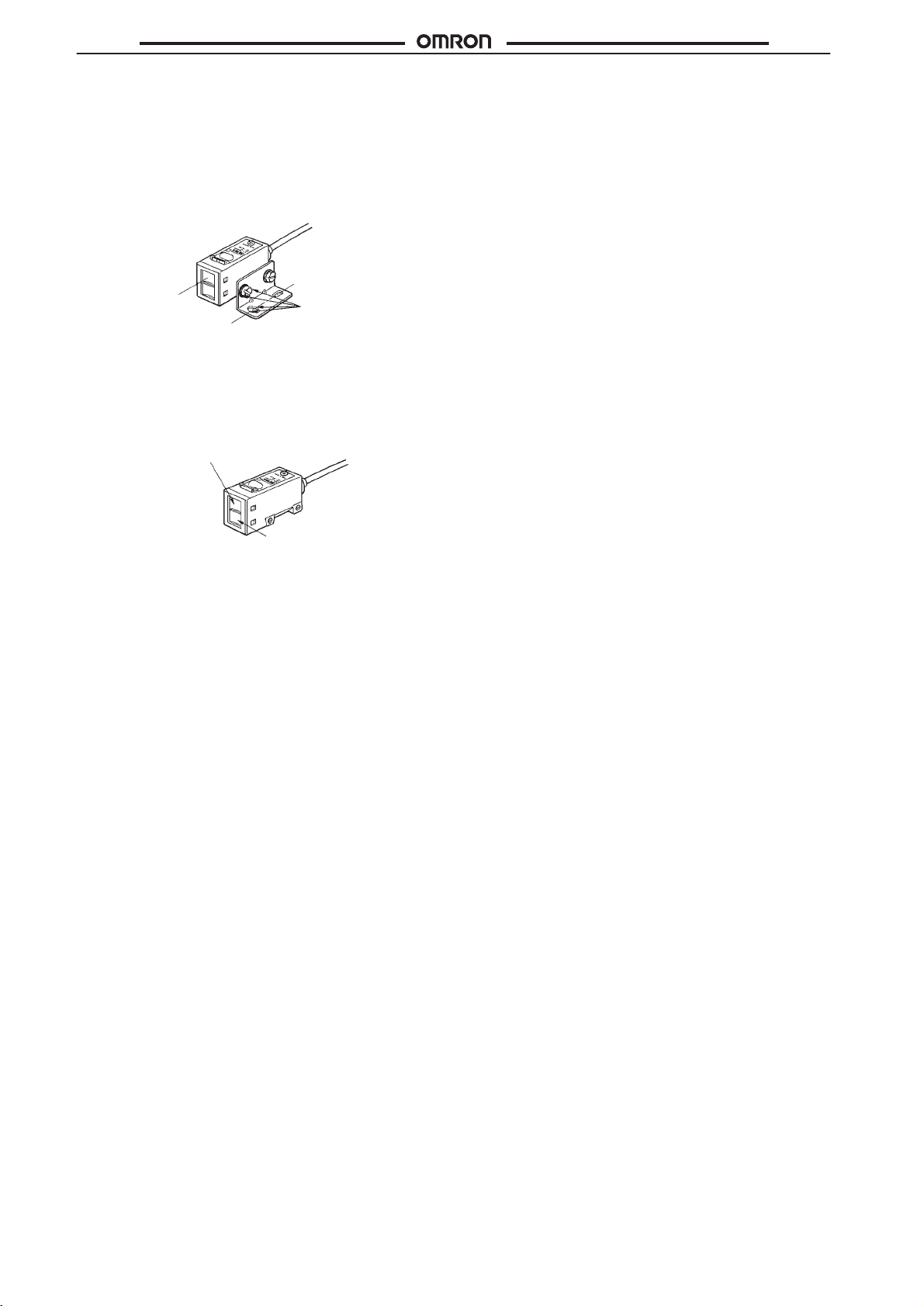
E3S-C
Optical Axis Adjustment
Direct the mounting axis of the mounting bracket in the direction
sensing objects will be
where
coincides with the mounting axis of the mounting bracket, which en
the user to adjust the optical axis of the E3S-C with ease.
ables
Optical Lock Holes
By
tightening the optical axis lock holes with screws, the mounting
bracket
will be in the direction of the optical axis of the E3S-C.
located. The optical axis of the E3S-C
-
E3S-C
Optical axis
Mounting axis
Four M4 optical
axis lock holes
Optical Axis of Through-bean Sensor
The
E3S-C through-beam models incorporates two
which
will be used as shown in the following illustration. When using
a slit, the slit must be on the side where the lens to be used is located.
Lens in use. The slit
must be on this side.
Lens not in use.
lenses, one of
22
Page 23

E3S-C
Replacing the E3S with the E3S-C
The
following is the conversion table for changing from the E3S to the E3S-C.
Models
Conventional models
E3S-5E4/5B4 E3S-CT11
E3S-5E41/5B41 E3S-CT61
E3S-R2E4/R2B4 E3S-CR11
E3S-R2E41/R2B41 E3S-CR61
E3S-DS30E4/DS30B4 E3S-CD11
E3S-DS30E41/DS30B41 E3S-CD61
Comparison
Item
Sensing distance
Response time
Enclosure rating
V
ertical operation panel
(sensitivity adjustor) (see note 1)
Outputs (see note 2)
Power supply voltage
LED for emitter
V
ariation in sensing distance
Dif
ference in direction between
optical axis and mounting
direction
Dark ON and light ON selection
(see note 1)
Dimensions (see note 1)
Dimensions with mounting
bracket attached (see note 1)
Mounting bracket
Material (lens)
Note: 1.
Especially take these items into consideration when replacing E3S models with E3S-C models.
2. When
connecting the E3S-C to a timer or counter with voltage input, be sure
power
supply lines. When the E3S-C is turned ON, a pulse signal may be output from the sensor
Through-beam:
Retroreflective:
Dif
fuse reflective:
Through-beam: 3 ms max.
Retroreflective/Dif
IP67 (with steel mounting bracket)
The sensitivity adjustor and indicator are on the
face where the lens is located.
V
oltage and current
12 to 24 VDC
Infrared
Not specified (approx. 150% max.)
Not specified (approx. 12° max.)
Selected with the connection of power supply
cord
Through-beam:
Dif
fuse reflective:
Through-beam/Retroreflective/Dif
Horizontal:
Vertical:
Iron
Polycarbonate Acrylic
55 x 40.2 x 32 mm
63 x 40.2 x 32 mm
E3S E3S-C
5 m
2 m (polarized)
30 cm (infrared type)
fuse reflective: 1 ms max.
±10%
23 x 20 x 55 mm
23 x 20 x 55 mm
fuse reflective:
E3S-C
New models
Through-beam:
Retroreflective:
Dif
fuse reflective:
1 ms max. (2 ms for 2-m dif
IP67, NEMA 6P, and IP67G (with stainless
mounting bracket)
The sensitivity adjustor and indicator are on the
top panel.
Open collector
10 to 30 VDC
Infrared (red for retroreflective models)
30% max.
±2°max.
Selector
Horizontal:
Vertical:
Through-beam/Retroreflective/Dif
Horizontal:
Vertical:
Stainless steel
to connect a 4.7-kΩ resistor between the output and
30 m
3 m (polarized)
70 cm/2 m (infrared type)
fusive models)
23 x 20 x 50 mm
57 x 20 x 23 mm
fuse reflective:
52.6 x 40.2 x 29.5 mm
60.6 x 40.2 x 32.2 mm
.
23
Page 24

E3S-C
E3S-C
ALL DIMENSIONS SHOWN ARE IN MILLIMETERS.
To
convert millimeters into inches, multiply by 0.03937. T
o convert grams into ounces, multiply by 0.03527.
Cat. No. E229-E1-3 In the interest of product improvement, specifications are subject to change without notice.
OMRON Corporation
Systems
28th Fl., Crystal T
1-2-27, Shiromi, Chuo-ku,
Osaka 540 Japan
Phone: 06-949-6012 Fax: 06-949-6021
Components Division H.Q.
24
ower Bldg.
Printed
in Japan
0397-1M (0194)
a
 Loading...