

Page 1
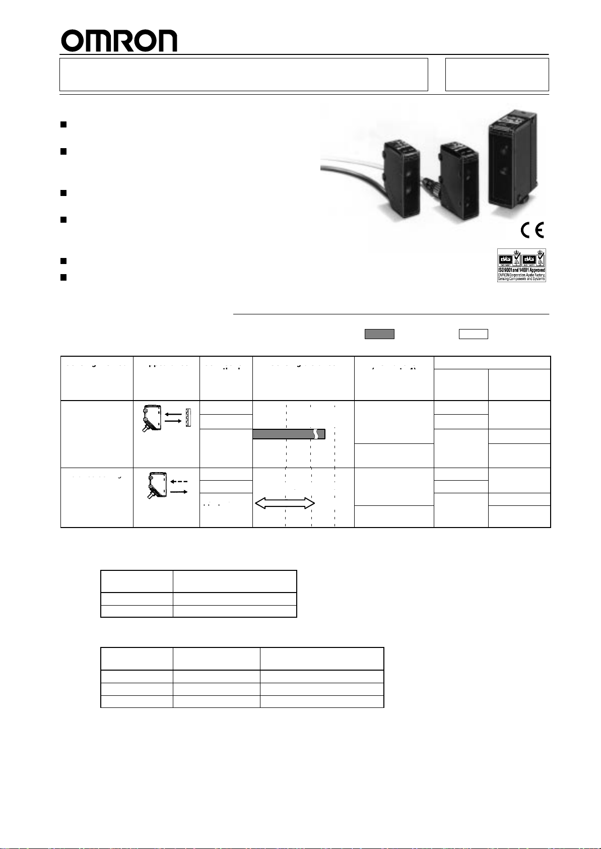
Long-distance Photoelectric Sensor
Se s g e od
ppea a ce
Co ec o
Se s gdsa ce
e uco
(
)
(see note 1)
function)
s a ce se g
()
ea
0.2 to 2 m
Retroreflective Models
Sensing distance of 10 m, with polarized light to
detect shiny objects.
Operation stability monitored by the stability
indicator.
Distance-setting Models
Distance-setting models with a long 2-m sensing
distance incorporate a teaching function.
Set sensing area (zone setting) function allows
detection of shiny objects with uneven surface.
Common Features
Meets
IEC
IP67 requirements, thus resisting water
E3G has an M12 rotary connector which ensures
easy maintenance.
.
Ordering Information
Sensors
MSR:
Mirror Surface Reflection
Sensing method
Retroreflective
(with MSR
function)
Distance-setting
Appearance Connection
method
Pre-wired
Connector
Terminal
block
Pre-wired E3G-L73
Connector
Terminal
block
Sensing distance
see note 1
10 m
(500
White paper (300 x 300 mm)
0.2
mm)
to 2 m
: Red light
T
imer function
(see note 4)
---
ON
or OFF delay
0 to 5 s (adjustable)
---
ON
or OFF delay
0 to 5 s (adjustable)
NPN/PNP
selector
(see note 2)
E3G-R13
E3G-R17
---
E3G-L77
---
E3G
: Infrared light
Model
Relay output
(see note 3)
---
E3G-MR19
E3G-MR19T
---
E3G-ML79
E3G-ML79T
Note: 1.
Figures in parentheses indicate the minimum required distances between the Sensors and Reflectors.
2. Specify
3. Specify
4.
the retroreflective model with or without Reflector by adding the suf
E3G-R13-G)
Suffix code
None Provided
-G
the conduit of the relay output model
E3G-MR19-G, E3G-ML79-US)
Suffix code
None PF1/2 (JIS) Provided
-G PG13.5 (CENELEC)
-US
For ON- and OFF-delay timers, Td1 and Td2 are independently variable.
E39-R2 Reflector
(retroreflective model)
Not provided (order separately)
and Reflector by adding the suf
Conduit
1
/2-14NPT Provided
(retroreflective model)
Not provided (order separately)
E39-R2 Reflector
fix code to the model number as shown below
fix code to the model number as shown below
. (e.g.,
. (e.g.,
1
Page 2
E3G
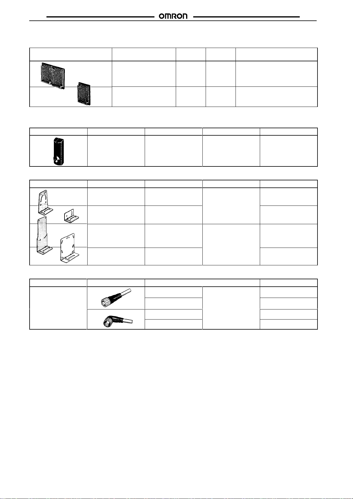
Accessories (Order Separately)
Reflectors
Shape
Note:
Figures in parentheses indicate the minimum required distance between the Sensors and Reflectors.
T
erminal Protection Cover for Side-pullout Cable
Shape Model
E39-L129 1
Mounting Brackets
Shape Model
E39-L131 1
Sensing
10 m
(500
6 m
(100
distance (typical)
mm)
(see note)
mm)
(see note)
Minimum order
Minimum order
Model Minimum
order
E39-R2 1
E39-R1 1
Applicable model
E3G-MR19 (T), ML79 (T)
Applicable model
E3G-R1j
E3G-L7j
Provided with E3G-R
E3G-MRjj
Remarks
jj,
and E3G-MR
---
Provided with rubber
bushing and cap for
pullout prevention in
vertical direction
---
jj-US
Remarks
Remarks
E3G
Sensor I/O Connectors
Cord Shape
Standard
Note:
Refer to the
Sensor I/O Connectors Catalog (X065)
E39-L132 1
E39-L135 1
E39-L136 1 ---
Straight
L-shaped
2 m
5 m
2 m
5 m
for details.
E3G-MR19 (T)
E3G-ML79 (T)
Cable type
Three-wire type
Rear-mounting use
Cable pulled out in the
downward direction
XS2F-D421-DC0-A
XS2F-D421-GC0-A
XS2F-D422-DC0-A
XS2F-D422-GC0-A
Model
2
Page 3
E3G
Material
E3G
Specifications
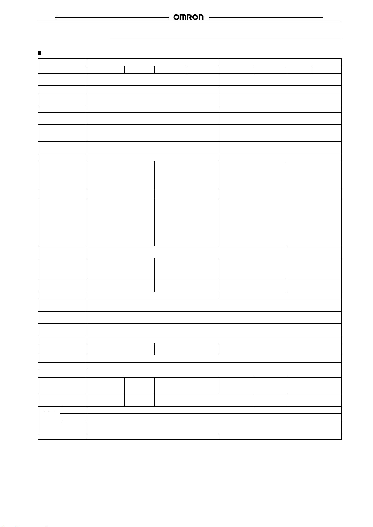
Ratings/Characteristics
Sensing
method
Item Model E3G-R13 E3G-R17 E3G-MR19 E3G-MR19T E3G-L73 E3G-L77 E3G-ML79 E3G-ML79T
Sensing distance
Setting distance
Standard sensing
object
Hysteresis (typical)
Directional angle
Reflectivity
characteristics
(black/white error)
Light source
(wavelength)
Spot size
Power supply voltage
Current/Power
consumption
Control output
Life expectancy
(relay output)
Circuit protection
Response time
Sensitivity adjustment
Ambient illumination
(receiver side)
Ambient temperature
Ambient humidity
Insulation resistance
Dielectric strength
V
ibration resistance
Shock resistance
Degree of protection
Connection method
W
eight
(packed state)
Material
Accessories Reflector*2, instruction sheet, and screwdriver for adjustment
Case
Lens
Mounting
Bracket
Note: *1.Figures
*2.
These accessories are not provided with the retroreflective models with the suf
10 m (500 mm)
(when using E39-R2)
Opaque: 80 dia. min.
Sensor: 1° to 5
Reflector: 40° min.
Red LED (700 nm)
10 to 30 VDC including 10%
(p-p) ripple
50 mA max.
Load power supply voltage:
30 VDC max.
Load current: 100 mA max.
Residual voltage:
NPN output: 1.2 V max.
PNP output: 2.0 V max.
Open collector output
(NPN/PNP selectable)
L.ON/D.ON selectable
Mechanical:
Electrical:
Protection from reversed power
supply connection, load
short-circuit, and mutual
interference
Operation or reset: 1 ms Operation or reset: 30 ms
One-turn adjuster
Incandescent lamp:
Sunlight:
Operating: –25°
(with no icing nor condensation)
Operating:
(with no condensation)
20 MΩ min. at 500 VDC
1,000 V
Destruction: 10 to 55 Hz, 1.5-mm double amplitude for 2 hours each in X, Y
Destruction: 500 m/s2 3 times each in X, Y, and Z directions
IEC60529 IP67 (with protective cover)
Pre-wired
(Standard
length: 2 m)
Approx. 150 g
PBT (polybutylene terephthalate)
Acrylic (PMMA)
Stainless steel (SUS304)
in parentheses indicate the minimum required distances between the Sensors and Reflectors.
Retroreflective (with MSR function)
*1
---
---
°
---
--12 to 240 VDC ± 10%
including 10% (p-p) max.
ripple
24 to 240 V
50/60 Hz
2 W max.
Relay output: SPDT
3 A (cos φ = 1) max. at 250
V
AC or 3 A max. at 30 VDC
L.ON/D.ON selectable
50,000,000 operations min. (switching frequency: 18,000 operations/h)
100,000 operations min. (switching frequency: 1,800 operations/h)
Protection from mutual
interference
max.
3,000 lx max.
10,000 lx max.
C to 55
°C/Storage: –30°
35% to 85%/Storage:
AC, 50/60 Hz for 1 min
M12
Connector
Approx. 50 g
35% to 95%
2,000 V
min
T
erminal block
Approx. 150 g
AC ± 10% at
,
C to 70
°C
AC, 50/60 Hz for 1
White paper (300 x 300 mm): 0.2 to 2 m
White paper (300 x 300 mm): 0.5 to 2 m
10% of setting distance
±
10% max. (at 1-m sensing distance)
Infrared LED (860 nm)
70 dia. max. (at 1-m sensing distance)
10 to 30 VDC including 10%
(p-p) ripple
60 mA max.
Load power supply voltage:
30 VDC max.
Load current: 100 mA max.
Residual voltage:
Open collector output
(NPN/PNP selectable)
L.ON/D.ON selectable
Protection from power supply
reverse connection, load
short-circuit, and mutual
interference
Operation or reset: 5 ms Operation or reset: 30 ms
T
eaching (in NORMAL or ZONE mode)
1,000 V
Pre-wired
(standard
length: 2 m)
*2
Instruction sheet and screwdriver for adjustment
Distance-setting
NPN output: 1.2 V max.
PNP output: 2.0 V max.
AC, 50/60 Hz for 1 min
, and Z directions
M12
Connector
Approx. 50 g
fix “-G.”
---
---
12 to 240 VDC ± 10%
including 10% (p-p) max.
ripple
24 to 240 V
50/60 Hz
2 W max.
Relay output: SPDT
3 A (cos φ = 1) max. at
250 V
AC or 3 A max. at
30 VDC
L.ON/D.ON selectable
Protection from mutual
interference
max.
2,000 V
1 min
T
erminal block
Approx. 150 g
AC ± 10% at
,
AC, 50/60 Hz for
3
Page 4
E3G
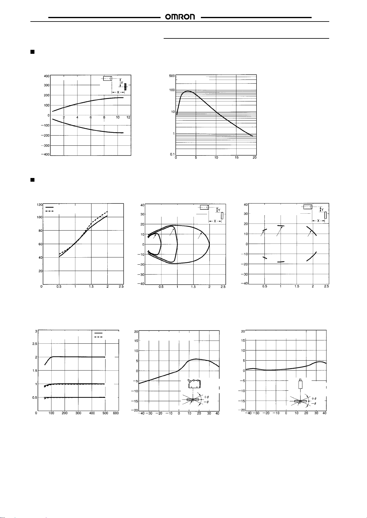
Engineering Data (Typical)
E3G-R/MR Retroreflective Models
E3G
Parallel Movement
(Typical)
E39-R2 Reflector
(mm)
Distance Y
Distance X (m)
E3G-L/ML Distance-setting Models
Spot Diameter vs.
Sensing Distance
Horizontal
Vertical
Spot Diameter (mm)
Sensing Zone in NORMAL Mode Sensing Zone in ZONE Mode
(mm)
Distance Y
Incident Output vs. Distance
E39-R2 Reflector
Incident output excess gain
ON level
Distance
setting:
Sensing object:
0.5
0.5, 1, and 2 m
White paper
300 x 300 mm
1 m
m
2 m
Distance
(mm)
Distance Y
(m)
Distance
Sensing object:
0.5
setting:
1 and 2 m
White paper
300 x 300 mm
m
1 m 2 m
Sensing Object Size vs.
Setting Distance
Distance setting:
0.5, 1, and 2 m
Sensing distance (m)
Side
length (one side) of
sensing object: d (mm)
Distance
White paper
Black paper
2 m
1 m
0.5 m
00
(m)
Sensing Object Angle
Characteristics
(Up and Down)
Sensing object: White paper
Sensing distance: 1 m
Sensing distance variation (%)
Distance
X (m)
Distance
Sensing Object Angle
(Left and Right)
Sensing object: White paper
Sensing distance: 1 m
(Upwards and
Downwards)
Inclination angle
Sensing object Sensing object
Inclination angle (
θ_)
Sensing distance variation (%)
Inclination angle (
X (m)
(Left and Right)
Inclination
angle
θ_)
4
Page 5
E3G
E3G
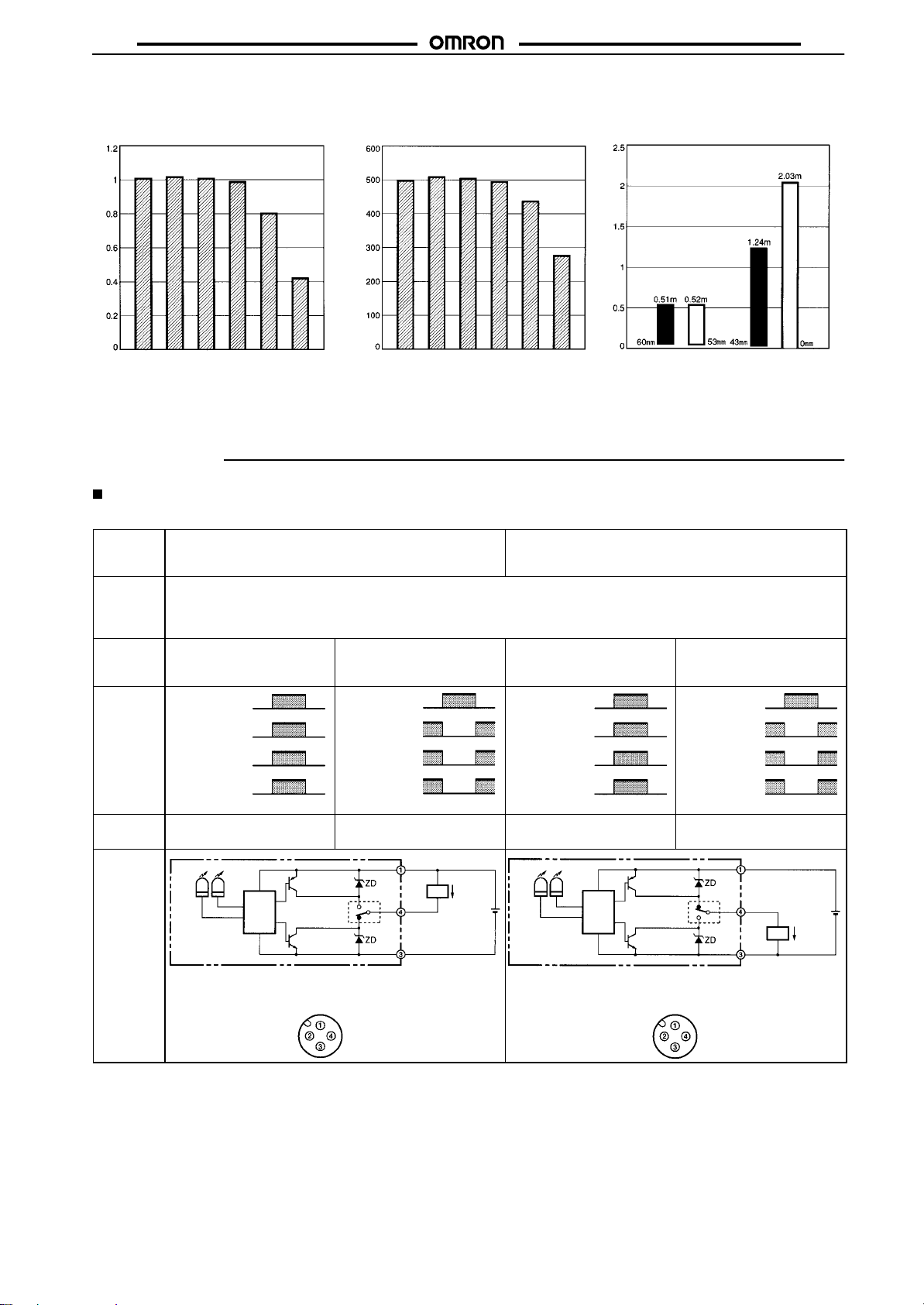
Sensing Distance vs. Sensing
Object Material
(at 1-m Setting Distance)
Sensing distance (m)
Sensing Distance vs. Sensing
Object Material
(at 500-mm Setting Distance)
Sensing distance (mm)
Material
White paper
Black paper
Fiberboard
Veneer
Black rubber
Mirror
White paper
Black paper
Fiberboard
Operation
Output Circuits
NPN/PNP Selection
Output
configura
tion
Model E3G-R13
Output
transistor
status
Timing
chart
Mode
selector
Output
circuit
NPN PNP
E3G-R17
E3G-L73
E3G-L77
Light ON Dark ON
Operation
indicator
(orange)
Output
transistor
Load
(relay)
Incident
Interrupted
ON
OFF
ON
OFF
Operate
Reset
(Between brown and black)
Operation
indicator
(orange)
Output
transistor
Load
(relay)
Incident
Interrupted
ON
OFF
ON
OFF
Operate
Reset
(Between brown and black)
Light ON (L/ON) Dark ON (D/ON) Light ON (L/ON) Dark ON (D/ON)
Operation
indicator
Orange
Note: Set the NPN or PNP selector to NPN.
Stability
indicator
Green
Connector
Main
circuit
PNP
output
transistor
NPN or PNP
output selector
NPN output
transistor
Pin Arrangement
(see
note)
Brown
Black
Blue
10 to 30 VDC
100 mA
Load
max.
Control output
0
V
Close-range Characteristics
Sensing distance (m)
Black
Material
Veneer
Black rubber
Mirror
Light ON
Incident
Interrupted
Operation
indicator
(orange)
Output
transistor
Load
(relay)
Operation
indicator
Orange
Note: Set the NPN or PNP selector to PNP.
ON
OFF
ON
OFF
Operate
Reset
(Between blue and black)
Stability
indicator
Green
Main
circuit
Connector
paper
(0.5
m)
PNP output
transistor
NPN or PNP
output selector
NPN output
transistor
Pin Arrangement
White
paper
(0.5 m)
Material
Dark ON
Operation
indicator
(orange)
Output
transistor
Load
(relay)
Black
White
paper
paper
(2 m)
(2 m)
(teaching distance m)
Incident
Interrupted
ON
OFF
ON
OFF
Operate
Reset
(Between blue and black)
Brown
10 to 30 VDC
(see
note)
Black
Control output
100 mA
Load
Blue
max.
0
V
Pin 2 is open.
Pin 2 is open.
5
Page 6
E3G
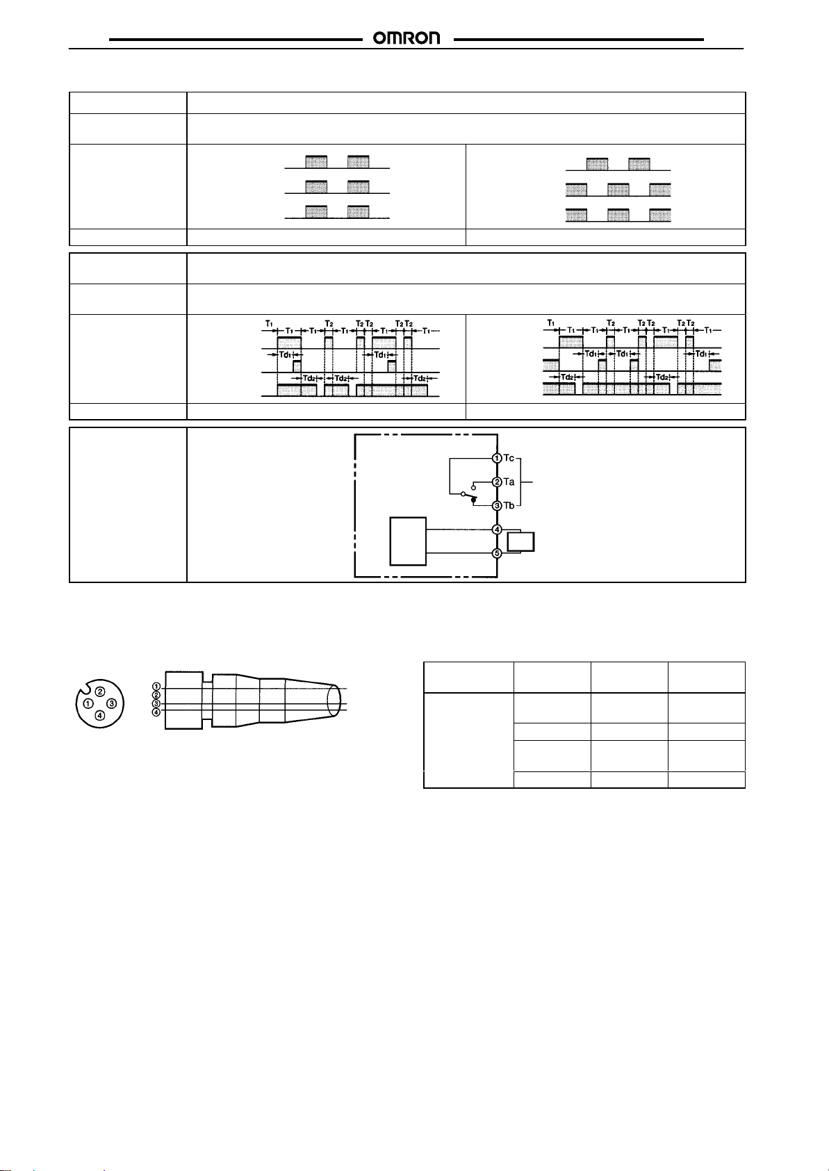
Relay Output
Timer
function
Model E3G-MR19
T
iming chart
Mode selector
T
imer function
Light-ON (L/ON) Dark-ON (D/ON)
ON or OFF delay
Operation
indicator
(orange)
Ta
Incident
Interrupted
ON
OFF
ON
OFF
0 to 5 s (adjustable)
Model
T
iming chart
Incident
Interrupted
ON
ON delay
OFF
ON
OFF delay
OFF
Mode
selector
Light-ON (L/ON) Dark-ON (D/ON)
Output circuit
---
E3G-ML79
E3G-MR19T
E3G-ML79T
Operation
indicator
(orange)
Ta
Incident
Interrupted
ON delay
OFF delay
Incident
Interrupted
ON
OFF
ON
OFF
ON
OFF
ON
OFF
E3G
Note: Td1,
Td2: Delay time (0 to 5 s)
T1:
A period longer than the delay time.
T2:
A period shorter than the delay time.
For ON- and OFF-delay timers, Td1 and Td2 are independently variable.
Structure of Sensor I/O Connector
Pin No. Wire colors
Brown
Blue
Black
XS2F-D421-DC0-A
XS2F-D421-GC0-A
XS2F-D422-DC0-A
XS2F-D422-GC0-A
Main
circuit
Classification Wire
DC
Note: 1.
2. For
Contact output
(G6C Relay built in)
24
to 240 V
Power
supply
AC or
12 to 240 VDC
(no polarity order
restricted)
color
Connector
pin No.
Brown 1 Power
--- 2 ---
Blue 3 Power
Black 4 Output
Pin 2 is not used.
details, refer to the
(X065)
.
Sensor I/O Connectors Catalog
Use
supply (+V)
supply (0 V)
6
Page 7
E3G
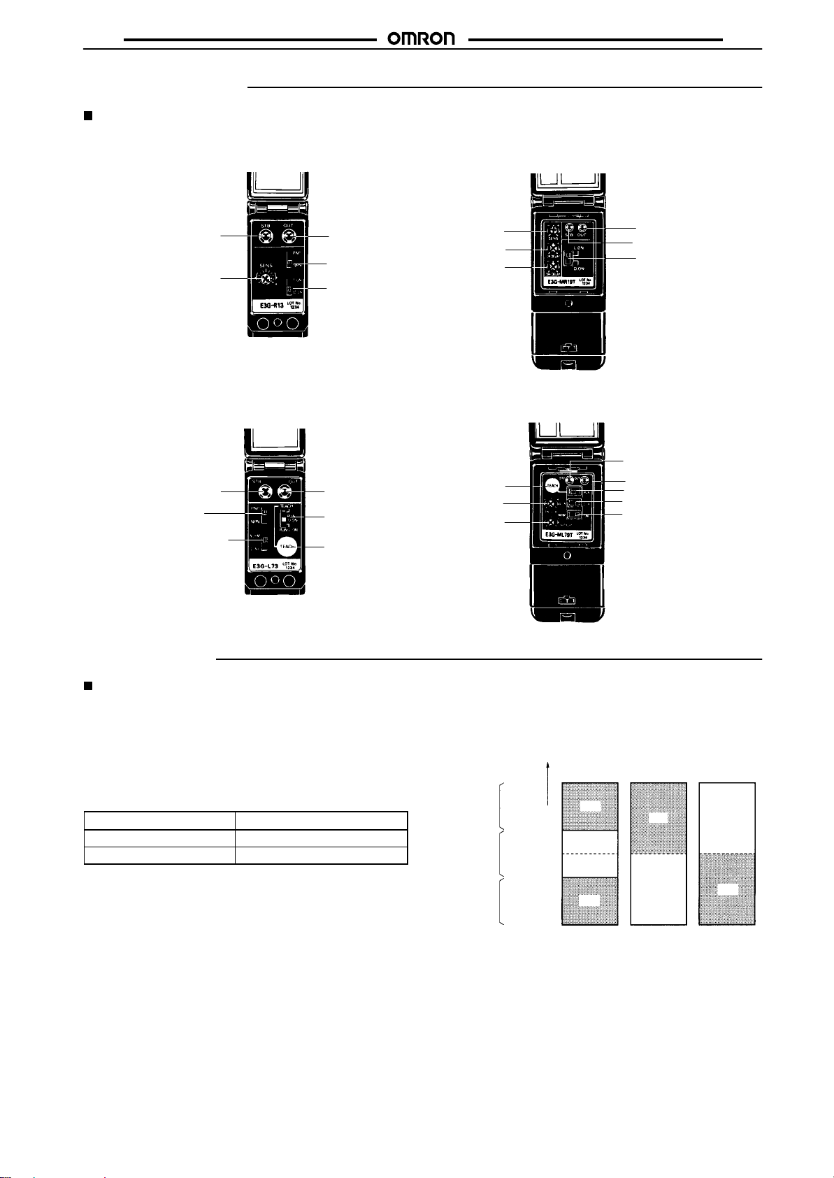
Nomenclature
Control Panels
Retroreflective
E3G-R13 (Pre-wired Model)
E3G-R17 (Connector Model)
E3G
E3G-MR19 (Terminal Block Model)
E3G-MR19T (Terminal Block Model with Timer)
Stability indicator
(Green)
Sensitivity adjuster
Note: The
Distance-setting
ON- or OFF-delay adjuster is not available with the E3G-MR19.
E3G-L73 (Pre-wired Model)
E3G-L77 (Connector Model)
Stability indicator (Green)
Teaching indicator (Red and green)
PNP/NPN selector
NORMAL/ZONE selector
Note: The
ON- or OFF-delay adjuster is not available with the E3G-ML79.
Operation indicator
(Orange)
PNP/NPN selector
L.ON/D.ON selector
Operation indicator
(Orange)
Mode selector:
TEACH, RUN (D-ON),
RUN (L.ON)
TEACH button
Sensitivity adjuster
ON-delay adjuster
(see note)
OFF-delay adjuster
(see note)
Operation indicator (Orange)
Stability indicator (Green)
L.ON/D.ON selector
E3G-ML79 (Terminal Block Model)
E3G-ML79T (Terminal Block Model with Timer)
Stability indicator (Green)
Teaching indicator (Red and green)
TEACH button
ON-delay adjuster
(see note)
OFF-delay adjuster
(see note)
Operation indicator (Orange)
TEACH/RUN selector
L.ON/D.ON selector
NORMAL/ZONE selector
Installation
E3G-R/MR
Designing
Power
Supply
A
power supply with full-wave rectification can be connected to the
E3G-MR19(T).
Wiring
The
tensile strength of the cable during operation should not exceed
the
values shown below
Model
E3G-R13, E3G-MR19(T)
E3G-R17
.
T
ensile strength (torque)
50 N max.
10 N max.
Adjustments
Indicators
following illustration indicates the operation levels of the E3G.
The
Set
the E3G so that it will work within the stable operation range.
Stability indicator
(green)
Stable
operation
range
(see note)
Unstable
operation
range
(see note)
Stable
operation
range
(see note)
Note: If
the operation level is set to the stable operation range, the
E3G
ing
influenced by temperature change, voltage
dust,
Incident level
Operation
level x 1.2
Operation level
Operation
level x 0.8
ON
OFF
ON
will operate with the highest reliability and without be
or setting change. If the operation level cannot be set
to the stable operation range, pay close attention to environmental
changes while operating the E3G.
Operation indicator (orange)
L. ON D. ON
ON
OFF
fluctuation,
OFF
ON
-
7
Page 8
E3G
E3G-L/ML
Designing
Power
Supply
A
power supply with full-wave rectification can be connected to the
E3G-ML79(T).
Wiring
The
tensile strength of the cable during operation should not exceed
the
values shown below
Model
E3G-L73, E3G-ML79(T) 50 N max.
E3G-L77
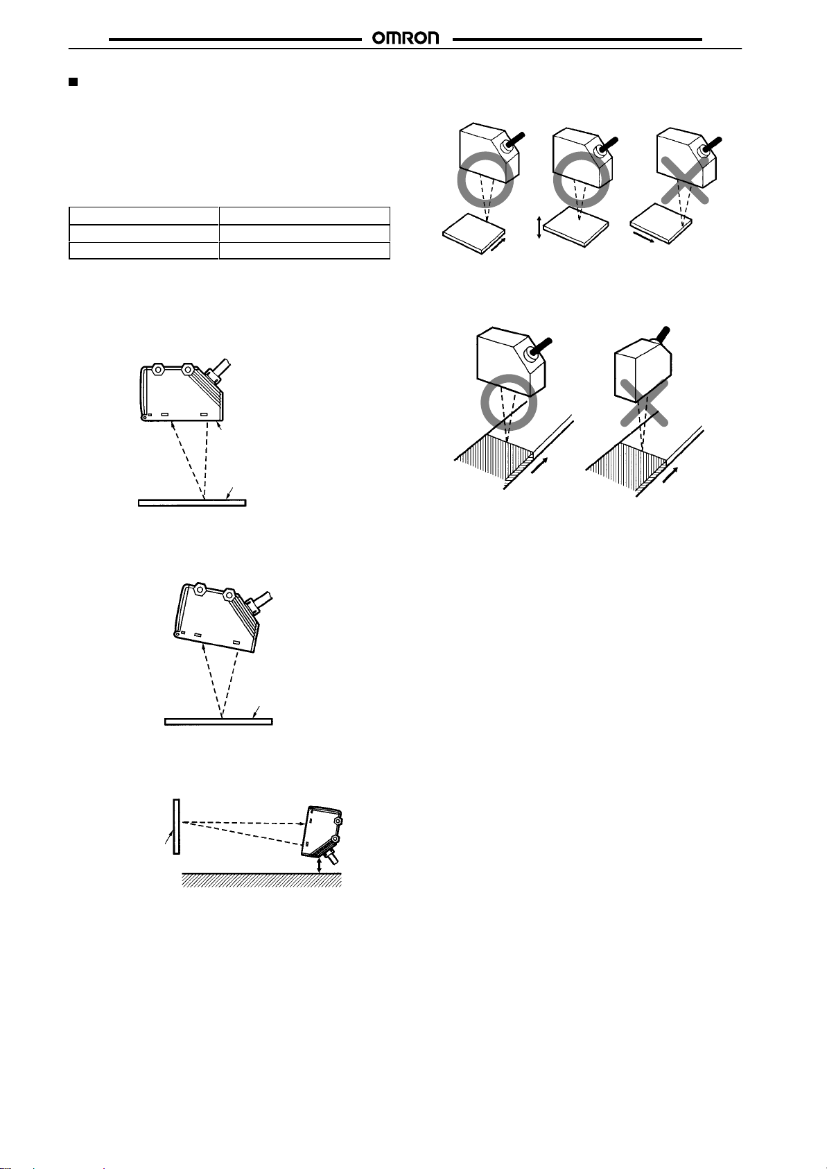
Mounting
Mounting Directions
Make sure that the sensing side of the Sensor is parallel with the
of each sensing
surface
the sensing object.
.
T
ensile strength (torque)
10 N max.
object. Do not incline the Sensor towards
Sensing side
Make
the
following.
sure not to
install the Sensor in the incorrect direction. Refer to
Correct Correct Incorrect
Sensing
object
Install
the Sensor as shown in the following if
greatly dif
Moving direction
Moving direction
fers in color or material.
Sensing
object
Moving direction
Correct Incorrect
E3G
Sensing
object
each sensing object
Surface of sensing object
If
the sensing object has a glossy surface, incline the Sensor by 5° to
10°
as shown below, provided that the Sensor is not influenced by
any
background objects.
Glossy object
If there is a mirror-like object below the Sensor
, the Sensor may not
be in stable operation. Therefore, incline the Sensor or keep the
Sensor
a distance away from the mirror-like object as shown
Sensing object
Mirror-like object
below
Moving direction
Moving direction
Others
If
a teaching data error occurs with the
due
to a power failure or static noise, perform the teaching operation
of
the Sensor again.
.
operation indicator flashing
8
Page 9
E3G
E3G-L/ML
Adjustments
Adjustment
1
2
3
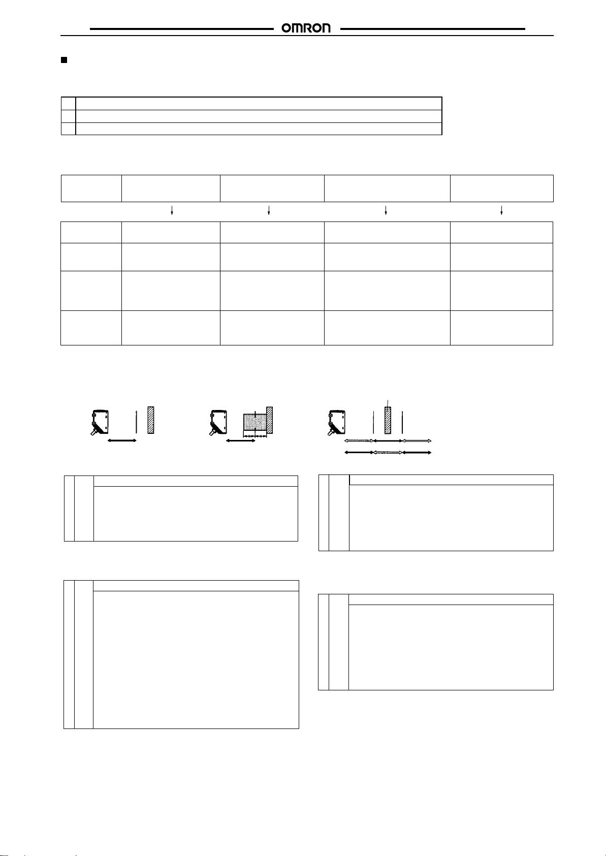
Distance Setting (Teaching)
Select
Steps
Install, wire, and turn ON the Sensor
Perform sensitivity adjustments (teaching). Refer to
.
Distance Setting (T
Check that the mode selector is set to RUN.
the most appropriate teaching method in reference to the following descriptions.
eaching)
below
E3G
.
Application
Teaching
Setting
method
Set threshold
Output ON range
La: Distance equivalent to threshold (a)
Lb: Distance equivalent to threshold (b)
Normal
Mode
1.
Normal One-point T
E3G-L/ML
Teaching without sensing objects
(i.e., teaching the background).
Normal one-point teaching
Press the TEACH button
with the background object.
Threshold (a) is set to a distance in front of the background of 20% of the background distance.
The output is ON between
the Sensor and La.
eaching
Threshold
a
(La)
Background
ON
2.
Normal T
Setting a threshold in the middle
between the background and
sensing object for operation.
Press the TEACH button with the
background object and with the
sensing object.
Threshold (a) is set approximately
in the middle between the background and sensing object.
The output is ON between the
Sensor and La.
wo-point T
E3G-L/ML
Object
ON ON
Normal One-point Teaching
Operation
1. Set the mode selector to TEACH.
2. Set the NORMAL/ZONE mode selector to NORMAL.
3. Press the TEACH button with no sensing object
ProcedureProcedure
Note: Perform normal one-point teaching with the background.
Normal T
(i.e., teach the background). The teaching indicator (red) will turn ON.
4. Set the mode selector to RUN.
(Set to L-ON or D-ON mode.)
wo-point Teaching
Operation
1. Set the mode selector to TEACH.
2. Set the NORMAL/ZONE mode selector to NORMAL.
3. Press the TEACH button with a sensing object located at the sensing
position. The teaching indicator (red) will turn ON.
4. Move the sensing object and press the TEACH button with the background.
• If
the teaching is successful, the teaching indicator (green) will turn
ON.
• If
the teaching is not successful, the teaching indicator (red) will start
5. If
to flash.
the
teaching is successful, set the mode selector to RUN to complete
the teaching operation.
the E3G to
Set
to the application.
If the teaching is not successful, change the set distance and object
sensing position and repeat two-point teaching from step 3.
light- or dark-ON mode with the mode selector according
eaching
Threshold a
(La)
Background
Detection of glossy objects in front
of the background.
Zone teachingNormal two-point teaching
Press the TEACH button with the
background object (conveyor
Thresholds (a and b) are set in the
sensing distance on condition that the
difference between these thresholds
are approximately 10% of the whole
sensing distance.
The output is ON between La and Lb.
Zone
Mode
Zone Teaching
E3G-L/ML
L-ON
D-ON
Zone T
1. Set the mode selector to TEACH.
2. Set the NORMAL/ZONE mode selector to ZONE.
3. Press the TEACH button with the background.
ProcedureProcedure
4. Set the mode selector to RUN.
Note: Perform zone teaching with the background.
Background
Threshold
a (La)
OFF
OFF
ON
eaching
• The teaching indicator (red) will turn ON first. Then the teaching
indicator (green) will turn ON.
(Set to L-ON or D-ON mode.)
, etc.).
Threshold b (Lb)
OFF
ON
Operation
Setting the maximum sensing
distance of the Sensor.
Maximum distance setting
(in normal mode)
Press the TEACH button for
longer than three seconds.
The threshold is set so that the
stability indicator will turn ON at
approximately 2 m if the sensing
object is white paper.
The output is ON whenever
the sensing object is located
between the Sensor and at a
distance of 2.2 m.
Maximum Distance Setting (in Normal Mode)
Operation
1. Set the mode selector to TEACH.
2. Set the NORMAL/ZONE mode selector to NORMAL.
3. Press the TEACH button for 3 s or more.
• The teaching indicator (red) will turn ON.
• The
teaching indicator (green) will turn ON in
4. If
teaching was successful.
the teaching is successful, set the mode selector to RUN to complete
the teaching operation.
(Set to L-ON or D-ON mode.)
3 s. This means that
9
Page 10
E3G
E3G
E3G-Mj(T)
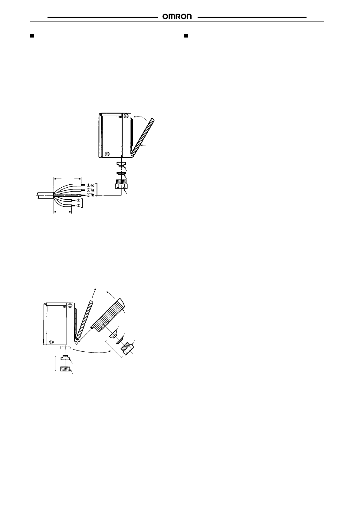
Wiring
The
cable with an external diameter of 6 to 8 mm is
Be
sure to attach the cover with screws securely in order to maintain
the
water- and dust-resistive properties of the product.
The conduit screw size is JIS B0202 PF1/2.
T
erminal Cover
Do
not tighten the terminal protection cover with wires pinched be
the Sensor and the cover in order to maintain
tween
dust-resistive
properties of the product.
Recommended
63
mm
Output
Power supply
33 mm
Changing to Side-pullout Cable from Verticalpullout Cable
Procedure
1. Remove
the present cover
2. Attach the E39-L129 Terminal Protection Cover for
side-pullout
3. Remove
E3G.
cable.
the clamping nut, washer
These are used for the side-pullout cable.
4. Attach the rubber bushing and cap provided with the
E39-L129
Note: *Provided
to the E3G as replacements.
(4)
Rubber bushing
Cap*
with the E39-L129.
.
, and rubber bushing of
(1) (2)
(2)
(3)
*
recommended.
the water- and
Example
Rubber bushing
Washer
Clamping nut
E39-L129 Terminal
Protection Cover
Rubber bushing
Washer
Clamping nut
Terminal
protection
cover
the
All E3G Models
Designing
Load
Relay Contact
If
E3G is connected to a load with contacts that spark when the load
is
turned OFF (e.g., a contactor or valve), the normally-closed
may
be turned ON before the normally-open side is turned OFF or
vice-versa. If both normally-open output and normally-closed out-
are used simultaneously
put
-
Refer
to OMRON’
s
of surge suppressors.
Power Reset Time
The Sensor needs 100 ms to be ready to operate after it is turned
ON.
The devices connected to
until
the Sensor
to separate power supplies, be sure to turn ON the Sensor
nected
is ready to operate. If the Sensor and load are con
first.
Power OFF
A single pulse signal may be output from the Sensor immediately
after it is turned OFF. This will occur more frequently if a timer or
counter
is connected to the Sensor and power is supplied
or counter independently
er
the
timer or counter from the built-in power supply of the Sensor
Power Supply
a standard switching regulator is used, be sure to ground the
If
(frame ground) and G (ground) terminals, otherwise the Sensor
malfunction due to the switching noise of the regulator
may
Repeated Cable Bending
Do not bend the sensor cable repeatedly
High-tension Lines
Do
not wire power lines or high-tension lines alongside the lines of
the
Sensor in the same conduit, otherwise the Sensor may be dam
or may malfunction due to induction. Be sure to wire the lines
aged
of the Sensor separated from power lines or high-tension lines or
in an exclusive, shielded conduit.
laid
Wiring
The
E3G has a built-in function to protect the E3G from load short-
circuiting. If load short-circuiting results, the output will be turned
In that case, check the wiring and turn ON the E3G again so
OFF.
that
the short-circuit protection circuit will be reset.
operate
if the output current flow is at least 2.0 times the rated load
current.
If an inductive load is connected to
the
inrush current does not exceed 1.2 times the rated load
The
cable can be extended up to a total length of 100 m, on condition
that
the thickness of the wire is at least 0.3 mm.
Mounting
Mounting Conditions
If
Sensors are mounted face-to-face, make sure that
cross
each other
Be sure to install the Sensor carefully so that the directional
range of the Sensor will not be directly exposed to intensive light,
such
as sunlight, fluorescent light, or incandescent light.
Do
not strike the Photoelectric Sensor with a hammer or any
tool
during the installation of the Sensor
water-resistive
Use M4 screws to mount the Sensor
When
mounting the case, make sure that the tightening torque ap
plied
to each screw does not exceed 1.2 N S m.
. Otherwise, mutual interference may result.
properties.
, apply an
PCB Relays Catalog (X33)
surge suppressor to the load.
for typical examples
the Photoelectric Sensor must wait
. Therefore, be sure to supply power to
.
the E3G, make sure that
, or the Sensor will loose its
.
side
to the tim
.
FG
.
This function will
current.
no optical axes
angle
other
-
-
-
-
10
Page 11

E3G
E3G
M12 Connector
Be sure to connect or disconnect the M12 connector after turning
OFF
the Sensor
sure to hold the connector cover when connecting or
Be
the M12 connector
ing
Secure the M12 connector by hand. Do not use any pliers, other-
wise
the connector may be damaged.
If
the M12 connector is not connected securely
protection of the Sensor may not be maintained or the connector
be disconnected due to vibration.
may
W
ater Resistance
Do not use the product in water
Tighten
to
a torque of 0.3 to 0.5 N S m in order to ensure water resistivity
.
disconnect
.
, the proper degree of
, in rain, or outdoors.
the operation cover screws and terminal block cover screws
Maintenance and Inspection
Cleaning
Paint thinner damages the casing of the E3G. Do not apply paint
-
to clean the E3G.
thinner
Others
Operating Environment
Do
not install the E3G in the following locations, otherwise the E3G
may
malfunction.
• Places with excessive dust.
• Places with corrosive gases.
• Locations
• Locations where the product is directly exposed to vibration or
.
shock.
directly exposed
to sprays of water
, oil, or chemicals.
11
Page 12
E3G
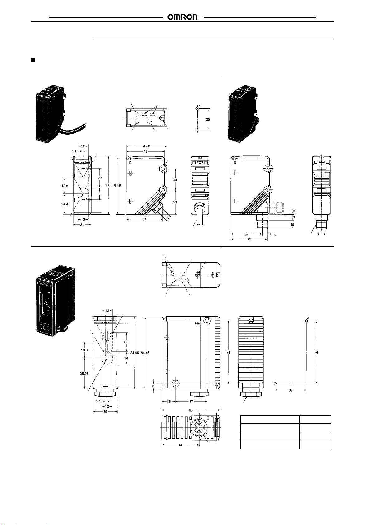
Dimensions
Note: All
Sensors
Retroreflective Models
units are in millimeters unless otherwise indicated.
E3G
E3G-R13 Pre-wired Model
Operation indicator (orange)
Receiver
R7
Emitter
R11
E3G-MR19 and E3G-MR19T
Terminal Block Models
Stability indicator
(green)
Operation indicator (orange)
Stability indicator
(green)
Mounting
Operation mode selector
Sensitivity
adjuster
M2.6
Two, 4.5-dia.
mounting
holes
Vinyl-insulated round cable
with three conductors, 6 dia.
(17 x 0.16 dia.); standard
length: 2 m
Operation
mode selector
Holes
Two, M4
E3G-R17 Connector Model
Note: All dimensions other than the
M2.6
ones specified below are the
same as the corresponding dimensions of E3G-R13.
M12 Connector
10.5 dia.
Receiver
R7
Emitter
R11
Sensitivity adjuster
OFF-delay adjuster
ON-delay adjuster
Two, 4.5-dia.
mounting holes
See the table.
Note: The ON- or OFF-delay adjuster is not
available with the E3G-MR19.
Mounting
Clamping nut (opposing side: 22)
Applicable cable: 6 to 8 dia.
Holes
Two, M4
Conduit Suffix
PF1/2 (JIS B0202)
None
PG13.5 (CENELEC) -G
1
/2-14NPT -US
code
12
Page 13
E3G
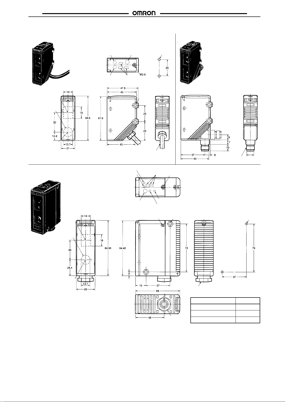
Distance-setting Models
E3G
E3G-L73 Pre-wired Model
Operation indicator (orange)
Stability indicator (green)
Teaching indicator (red/green)
Receiver
14-dia. lens
Emitter
E3G-ML79 and E3G-ML79T
Terminal Block Models
TEACH button
Operation
mode selector
Vinyl-insulated round cable
with three conductors, 6 dia.
(17 x 0.16 dia.); standard
length: 2 m
Operation indicator (orange)
Stability indicator (green)
Teaching indicator (red/green)
Mounting
Two, 4.5-dia.
mounting
holes
Operation mode
selector
Holes
Two, M4
E3G-L77 Connector Model
Note: All dimensions other than the
M2.6
ones specified below are the
same as the corresponding dimensions of the E3G-L73.
M12 Connector
10.5 dia.
Receiver
14-dia. lens
Emitter
TEACH button
OFF-delay adjuster
ON-delay adjuster
M2.6 nut
Note: The ON- or OFF-delay adjuster is not
Two, 4.5-dia. mounting holes
Clamping nut (opposing side: 22)
Applicable cable: 6 to 8 dia.
PF1/2 (JIS B0202)
See the table.
PG13.5 (CENELEC) -G
1
/2-14NPT -US
available with the E3G-ML79.
Mounting
Conduit Suffix
None
Holes
Two, M4
code
13
Page 14
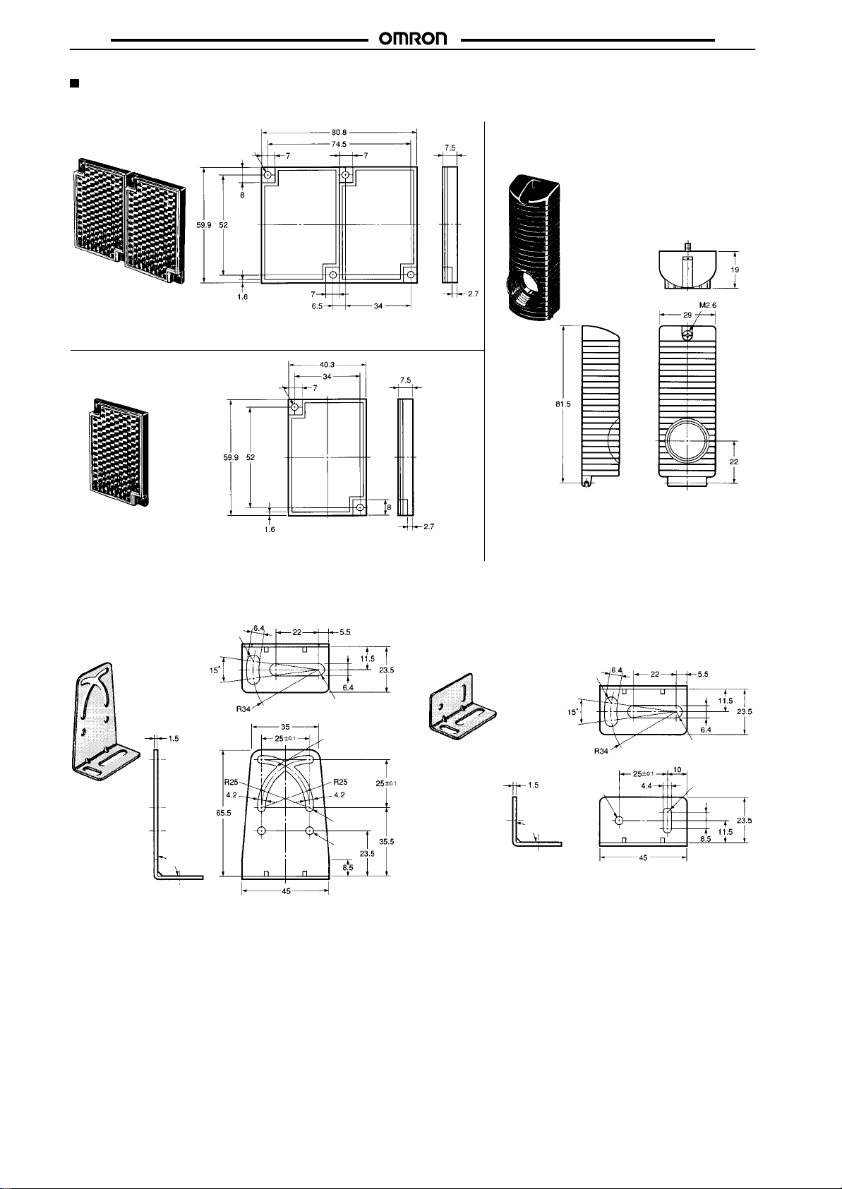
E3G
Accessories (Order Separately)
E3G
Reflectors
E39-R2
Material
Surface: Acrylic resin
Backside: ABS resin
Note:
Supplied with E3G-R
E39-R1
Material
Surface: Acrylic resin
Backside: ABS resin
Four, 3.5 dia.
jj, E3G-MRjj
Two, 3.5 dia.
, and E3G-MR
jj-US.
Terminal Protection Cover for
Side-pullout Cable
E39-L129
Note: 1. The cover is provided with a rubber
bushing and cap to prevent the cable
from
being pulled out vertically
2. Refer
to page
of the product.
od
10 for the mounting
.
meth
-
Mounting Brackets
E39-L131
90°±1°
Material: Stainless steel (SUS304)
Two, R3.2
Two, R3.2
Four, R1
Four, R2.1
Two,
4.2 dia.
E39-L132
Two, R3.2
Two, R3.2
4.2 dia.
90°±1°
Material: Stainless steel (SUS304)
Two, R2.2
14
Page 15
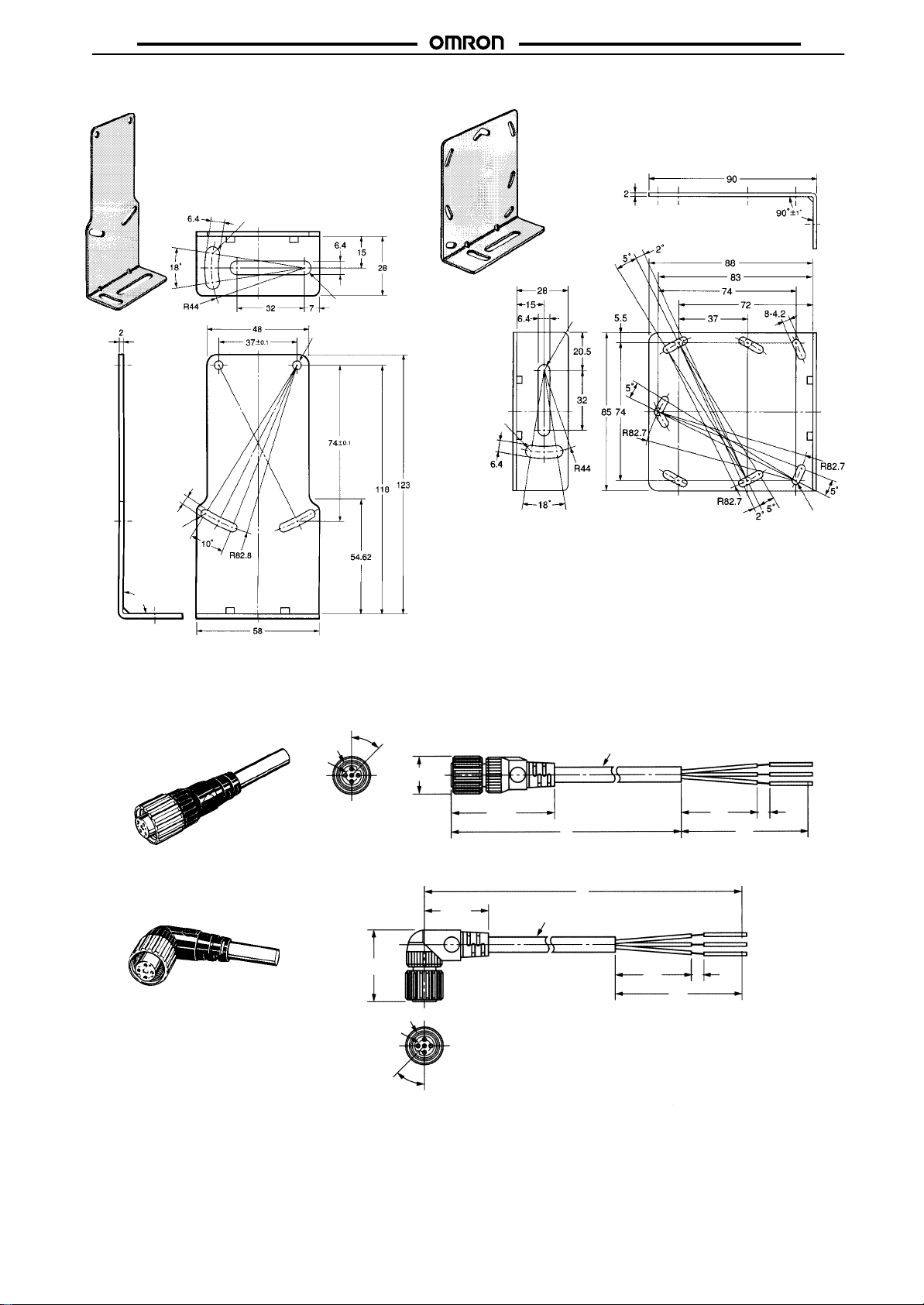
E3G
E39-L135 E39-L136
E3G
Material: Stainless steel (SUS304)
Two, 4.2
Four, R2.1
Two, R3.2
Two, R3.2
Two, 4.2 dia.
Two, R3.2
Material: Stainless steel (SUS304)
Two, R3.2
Fourteen,
R2.1
90°±1°
Sensor I/O Connectors
Straight
XS2F-D421-DC0-A (L=2 m)
XS2F-D421-GC0-A (L=5 m)
L-shaped
XS2F-D422-DC0-A (L=2 m)
XS2F-D422-GC0-A (L=5 m)
5 dia.
M12
45°
28.3
5 dia.
14.9 dia.
M12
25.3
40.7
6 dia.
6 dia.
5
30
L
L
30
50
50
5
45°
15
Page 16

E3G
Precautions
Do not ignore the following items that are essential for securing
safety
during Sensor operation.
• Do
not use the Sensor in locations with explosive or
gas.
• Do not use the Sensor in the water or electrically conductive
solutions.
• Do
not disassemble, repair
, or modify the product.
flammable
E3G
• Make sure that the power supply specifications, such as AC or
DC, are correct.
•
Do not apply voltage or current exceeding the rated ranges.
•
Do not make mistakes in wiring, such as mistakes in polarity
•
Be sure to connect the load correctly
•
Do not short-circuit the load terminals.
.
.
ALL DIMENSIONS SHOWN ARE IN MILLIMETERS.
To
convert millimeters into inches, multiply by 0.03937. T
o convert grams into ounces, multiply by 0.03527.
Cat. No. E278-E1-2 In the interest of product improvement, specifications are subject to change without notice.
OMRON Corporation
Industrial Sensors Division
Sensing Devices and Components Division H.Q.
28th Fl., Crystal T
1-2-27, Shiromi, Chuo-ku,
Osaka 540-6028 Japan
Phone: (81)6-6949-6012 Fax: (81)6-6949-6021
16
ower Bldg.,
Printed
in Japan
1298-3M (0998)
a
 Loading...