

Page 1

TRANSMISSION & DRIVELINE
Revision: October 2006
2007 G35 Sedan
A
B
SECTION DLN
CONTENTS
TRANSFER: ETX13B
BASIC INSPECTION ....................................
DIAGNOSIS AND REPAIR WORKFLOW ..........7
Work Flow .................................................................7
FUNCTION DIAGNOSIS ...............................8
AWD SYSTEM .....................................................8
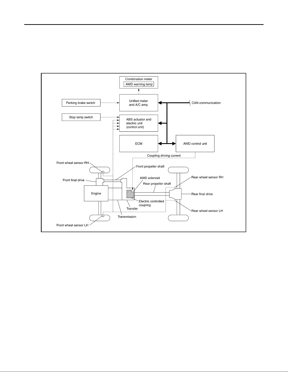
System Diagram ........................................................8
System Description ...................................................9
Component Parts Location . .....................................10
Component Description ...........................................11
DIAGNOSIS SYSTEM (AWD CONTROL
UNIT) ..................................................................
CONSULT-III Function (ALL MODE AWD/4WD) ....12
12
DRIVELINE
C1210 ECM .......................................................20
Description .......................... ... ....... ...... ....... ...... ........20
7
DTC Logic ................................................................20
Diagnosis Procedure ...............................................20
U1000 CAN COMM CIRCUIT ...........................21
Description .......................... ... ....... ...... ....... ...... ........21
DTC Logic ................................................................21
Diagnosis Procedure ...............................................21
U1010 CONTROL UNIT (CAN) .........................22
Description .......................... ... ....... ...... ....... ...... ........22
DTC Logic ................................................................22
Diagnosis Procedure ...............................................22
POWER SUPPLY AND GROUND CIRCUIT ....23
Description .......................... ... ....... ...... ....... ...... ........23
Diagnosis Procedure ...............................................23
C
DLN
E
F
G
H
I
J
K
COMPONENT DIAGNOSIS .........................14
C1201 AWD CONTROL UNIT ............................14
Description ..............................................................14
DTC Logic ...............................................................14
Diagnosis Procedure ........................... ... ... ... .... .......14
C1203 ABS ACTUATOR AND ELECTRIC
UNIT (CONTROL UNIT) .....................................
Description ..............................................................15
DTC Logic ...............................................................15
Diagnosis Procedure ........................... ... ... ... .... .......15
C1204 AWD SOLENOID ....................................16
Description ..............................................................16
DTC Logic ...............................................................16
Diagnosis Procedure ........................... ... ... ... .... .......16
Component Inspection ....... .... ... ... ... ........................18
C1205 AWD ACTUATOR RELAY .....................19
Description ..............................................................19
DTC Logic ...............................................................19
Diagnosis Procedure ........................... ... ... ... .... .......19
AWD WARNING LAMP ....................................25
Description .......................... ... ....... ...... ....... ...... ........25
Diagnosis Procedure ...............................................25
ECU DIAGNOSIS .........................................27
AWD CONTROL UNIT ......................................27
Reference Value ......................................................27
15
Wiring Diagram — AWD SYSTEM — .....................28
Fail Safe ..................................................................32
DTC Inspection Priority Chart ..................................33
DTC Index ...............................................................33
SYMPTOM DIAGNOSIS ..............................35
AWD SYSTEM SYMPTOMS .............................35
Symptom Table .......................................................35
AWD WARNING LAMP DOES NOT TURN ON
Description .......................... ... ....... ...... ....... ...... ........36
Diagnosis Procedure ...............................................36
DLN-1
...
L
M
N
O
P
36
Page 2

AWD WARNING LAMP DOES NOT TURN
Revision: October 2006
2007 G35 Sedan
OFF ....................................................................
Description ....................... .......................... ............. 37
Diagnosis Procedure .............................................. 37
37
HEAVY TIGHT-CORNER BRAKING SYMP-
TOM OCCURS ...................................................
Description ....................... .......................... ............. 38
Diagnosis Procedure .............................................. 38
38
VEHICLE DOES NOT ENTER AWD MODE .....39
Description ....................... .......................... ............. 39
Diagnosis Procedure .............................................. 39
REMOVAL AND INSTALLATION .............. 55
TRANSFER ASSEMBLY ................................... 55
Exploded View ........................................................55
Removal and Installation .........................................55
DISASSEMBLY AND ASSEMBLY ............ 58
FRONT CASE AND REAR CASE ..................... 58
Exploded View ........................................................58
Disassembly ........................ ................ ................ ....58
Assembly ................................................................62
Inspection ......................... ................ ................ .......67
AWD WARNING LAMP BLINKS QUICKLY .....40
Description ....................... .......................... ............. 40
AWD WARNING LAMP BLINKS SLOWLY ......41
Description ....................... .......................... ............. 41
Diagnosis Procedure .............................................. 41
NORMAL OPERATING CONDITION ................ 42
Description ....................... .......................... ............. 42
NOISE, VIBRATION AND HARSHNESS
(NVH) TROUBLESHOOTING ............................
NVH Troubleshooting Chart ............ .... ................... 43
43
PRECAUTION ............................................. 44
PRECAUTIONS .................................................44
Precaution for Supplemental Restraint System
(SRS) "AIR BAG" and "SEAT BELT PRE-TEN-
SIONER" ............................. ................. ...................
Service Notice or Precautions for Transfer ............. 44
44
PREPARATION ........................................... 45
PREPARATION .................................................45
Special Service Tools ............................................. 45
Commercial Service Tools ...................................... 46
ON-VEHICLE MAINTENANCE ................... 48
TRANSFER FLUID ............................................ 48
Inspection ............................................................... 48
Draining .................................................................. 48
Refilling ...................................... ............................. 48
ON-VEHICLE REPAIR ................................ 49
AWD CONTROL UNIT ....................................... 49
Exploded View ........................... ... .......................... 49
Removal and Installation ........................................ 49
FRONT OIL SEAL ............................................. 50
Exploded View ........................... ... .......................... 50
Removal and Installation ........................................ 50
REAR OIL SEAL ................................................ 52
Exploded View ........................... ... .......................... 52
Removal and Installation ........................................ 52
MAINSHAFT ...................................................... 69
Exploded View ........................................................69
Disassembly ........................ ................ ................ ....69
Assembly ................................................................70
Inspection ......................... ................ ................ .......70
FRONT DRIVE SHAFT AND DRIVE CHAIN ..... 72
Exploded View ........................................................72
Disassembly ........................ ................ ................ ....72
Assembly ................................................................73
Inspection ......................... ................ ................ .......74
SERVICE DATA AND SPECIFICATIONS
(SDS) .......................................................... 76
SERVICE DATA AND SPECIFICATIONS
(SDS) .................................................................
General Specifications ............................................76
76
FRONT PROPELLER SHAFT: 2S56A
SYMPTOM DIAGNOSIS ............................ 77
NOISE, VIBRATION AND HARSHNESS
(NVH) TROUBLESHOOTING ............................
NVH Troubleshooting Chart ....................................77
77
PREPARATION .......................................... 78
PREPARATION ................................................. 78
Commercial Service Tools ......................................78
ON-VEHICLE MAINTENANCE .................. 79
FRONT PROPELLER SHAFT ........................... 79
Inspection ......................... ................ ................ .......79
ON-VEHICLE REPAIR ............................... 80
FRONT PROPELLER SHAFT ........................... 80
Exploded View ........................................................80
Removal and Installation .........................................80
Inspection ......................... ................ ................ .......81
SERVICE DATA AND SPECIFICATIONS
(SDS) .......................................................... 82
DLN-2
Page 3

SERVICE DATA AND SPECIFICATIONS
Revision: October 2006
2007 G35 Sedan
(SDS) ..................................................................
General Specifications ............................................82
Propeller Shaft Runout ............................................82
Journal Axial Play ............ ... .... ... ... ...........................82
82
REAR PROPELLER SHAFT: 3S80A
SYMPTOM DIAGNOSIS ..............................
NOISE, VIBRATION AND HARSHNESS
(NVH) TROUBLESHOOTING ............................
NVH Troubleshooting Chart ....................................83
83
83
PREPARATION ...........................................84
PREPARATION ..................................................84
Commercial Service Tools ......................................84
SERVICE DATA AND SPECIFICATIONS
(SDS) ............................................................97
SERVICE DATA AND SPECIFICATIONS
(SDS) .................................................................
General Specifications .............................................97
Propeller Shaft Runout ............................................97
Journal Axial Play ....................................................97
97
REAR PROPELLER SHAFT: 3F80A-1VL107
SYMPTOM DIAGNOSIS ..............................98
NOISE, VIBRATION AND HARSHNESS
(NVH) TROUBLESHOOTING ...........................
NVH Troubleshooting Chart ....................................98
98
PREPARATION ...........................................99
A
B
C
DLN
E
ON-VEHICLE MAINTENANCE ....................85
REAR PROPELLER SHAFT ..............................85
Inspection ..................... ...........................................85
ON-VEHICLE REPAIR .................................86
REAR PROPELLER SHAFT ..............................86
Exploded View ........................................................86
Removal and Installation .........................................86
Inspection ..................... ...........................................88
SERVICE DATA AND SPECIFICATIONS
(SDS) ............................................................89
SERVICE DATA AND SPECIFICATIONS
(SDS) ..................................................................
General Specifications ............................................89
Propeller Shaft Runout ............................................89
Journal Axial Play ............ ... .... ... ... ...........................89
89
REAR PROPELLER SHAFT: 3S80A-R
SYMPTOM DIAGNOSIS ..............................
NOISE, VIBRATION AND HARSHNESS
(NVH) TROUBLESHOOTING ............................
NVH Troubleshooting Chart ....................................90
90
90
PREPARATION ...........................................91
PREPARATION ..................................................91
Commercial Service Tools ......................................91
ON-VEHICLE MAINTENANCE ....................92
REAR PROPELLER SHAFT ..............................92
Inspection ..................... ...........................................92
ON-VEHICLE REPAIR .................................93
PREPARATION .................................................99
Commercial Service Tools .......................................99
ON-VEHICLE MAINTENANCE .................. 100
REAR PROPELLER SHAFT ...........................100
Inspection ..............................................................100
ON-VEHICLE REPAIR ............................... 101
REAR PROPELLER SHAFT ...........................101
Exploded View .......................................................101
Removal and Installation .......................................101
Inspection ..............................................................104
SERVICE DATA AND SPECIFICATIONS
(SDS) ..........................................................105
SERVICE DATA AND SPECIFICATIONS
(SDS) ...............................................................
General Specifications ...........................................105
Propeller Shaft Runout ..........................................105
Journal Axial Play ..................................................105
105
FRONT FINAL DRIVE: F160A
SYMPTOM DIAGNOSIS ............................106
NOISE, VIBRATION AND HARSHNESS
(NVH) TROUBLESHOOTING .........................
NVH Troubleshooting Chart ..................................106
106
PRECAUTION ............................................107
PRECAUTIONS ...............................................107
Precaution Necessary for Steering Wheel Rota-
tion after Battery Disconnect .................................
Service Notice or Precautions for Front Final Drive
..
107
107
F
G
H
I
J
K
L
M
N
O
P
REAR PROPELLER SHAFT ..............................93
Exploded View ........................................................93
Removal and Installation .........................................93
Inspection ..................... ...........................................96
PREPARATION .........................................108
PREPARATION ...............................................108
Special Service Tools ............................................108
DLN-3
Page 4

Commercial Service Tools .....................................110
Revision: October 2006
2007 G35 Sedan
FUNCTION DIAGNOSIS ............................111
FRONT FINAL DRIVE ASSEMBLY ................ 111
System Diagram ........................................ ... .... .....111
ON-VEHICLE MAINTENANCE ..................112
FRONT DIFFERENTIAL GEAR OIL ................ 112
Inspection ..............................................................112
Draining .................................................................112
Refilling ...................................... ............................112
ON-VEHICLE REPAIR ...............................113
SIDE OIL SEAL ............................................... 113
RIGHT SIDE .................................... ... .... ... ... ............113
RIGHT SIDE : Exploded View ...............................113
RIGHT SIDE : Removal and Installation ................114
LEFT SIDE ............................................................... 114
LEFT SIDE : Exploded View ..................................114
LEFT SIDE : Removal and Installation ..................116
REMOVAL AND INSTALLATION ..............117
Preload Torque ..................................................... 144
Backlash ............................................................... 144
Companion Flange Runout ................................... 144
REAR FINAL DRIVE: R200
SYMPTOM DIAGNOSIS ...........................145
NOISE, VIBRATION AND HARSHNESS
(NVH) TROUBLESHOOTING ...........................
NVH Troubleshooting Chart ..................................145
145
PRECAUTION ...........................................147
PRECAUTIONS ................................................147
Service Notice or Precautions for Rear Final Drive . 147
PREPARATION .........................................148
PREPARATION ................................................148
Special Service Tools ................................... ... ... .. 148
Commercial Service Tools .................................... 151
FUNCTION DIAGNOSIS ...........................152
REAR FINAL DRIVE ASSEMBLY ...................152
System Diagram .............................. ... ... .... ... ... ..... 152
FRONT FINAL DRIVE ASSEMBLY ................ 117
Exploded View ........................... ... .........................117
Removal and Installation .......................................117
DISASSEMBLY AND ASSEMBLY ............119
SIDE SHAFT .................................................... 119
Exploded View ........................... ... .........................119
Disassembly ..........................................................120
Assembly ...............................................................120
Inspection After Disassembly ................................121
DIFFERENTIAL ASSEMBLY .......................... 122
Exploded View ........................... ... .........................122
Disassembly ..........................................................123
Assembly ...............................................................125
Adjustment ....................... .......................... ............130
Inspection After Disassembly ................................134
DRIVE PINION ................................................. 136
Exploded View ........................... ... .........................136
Disassembly ..........................................................137
Assembly ...............................................................138
Adjustment ....................... .......................... ............140
Inspection After Disassembly ................................143
SERVICE DATA AND SPECIFICATIONS
(SDS) ..........................................................
144
ON-VEHICLE MAINTENANCE ................. 154
REAR DIFFERENTIAL GEAR OIL ...................154
Inspection ......................... ................ ................ ..... 154
Draining ............................ ................ ................ ..... 154
Refilling ................................................................. 154
ON-VEHICLE REPAIR ..............................155
FRONT OIL SEAL ............................................155
2WD ......................................................................... 155
2WD : Exploded View ........................................... 155
2WD : Removal and Installation ............................ 156
AWD ........................................................................ 160
AWD : Exploded View ...........................................160
AWD : Removal and Installation ........................... 161
SIDE OIL SEAL ................................................166
2WD ......................................................................... 166
2WD : Exploded View ........................................... 166
2WD : Removal and Installation ............................ 167
AWD ........................................................................ 168
AWD : Exploded View ...........................................168
AWD : Removal and Installation ........................... 169
REMOVAL AND INSTALLATION ............. 171
SERVICE DATA AND SPECIFICATIONS
(SDS) ................................................................
General Specifications ...........................................144
Drive Gear Runout .................................................144
Differential Side Gear Clearance ...........................144
144
REAR FINAL DRIVE ASSEMBLY ...................171
2WD ......................................................................... 171
2WD : Exploded View ........................................... 171
2WD : Removal and Installation ............................ 171
DLN-4
Page 5

AWD ................................ .......................... ...............
Revision: October 2006
2007 G35 Sedan
AWD : Exploded View .. ... ... .... ... ... ... .... ... ...............172
AWD : Removal and Installation ........................... 172
172
Service Notice or Precautions for Rear Final Drive ..220
A
PREPARATION .........................................221
DISASSEMBLY AND ASSEMBLY ............174
DIFFERENTIAL ASSEMBLY ...........................174
2WD .........................................................................174
2WD : Exploded View ...........................................174
2WD : Disassembly ............................. ... ...............175
2WD : Assembly ........... ... ......................................177
2WD : Adjustment ..................... ... ... .... .................. 181
2WD : Inspection After Disassembly ..................... 186
AWD ................................ .......................... ...............186
AWD : Exploded View .. ... ... .... ... ... ... .... ... ...............186
AWD : Disassembly ..............................................187
AWD : Assembly ...................................................190
AWD : Adjustment .................................................194
AWD : Inspection After Disassembly ....................198
DRIVE PINION ..................................................199
2WD .........................................................................199
2WD : Exploded View ...........................................199
2WD : Disassembly ............................. ... ...............200
2WD : Assembly ........... ... ......................................201
2WD : Adjustment ..................... ... ... .... .................. 203
2WD : Inspection After Disassembly ..................... 206
AWD ................................ .......................... ...............207
AWD : Exploded View .. ... ... .... ... ... ... .... ... ...............207
AWD : Disassembly ..............................................208
AWD : Assembly ...................................................209
AWD : Adjustment .................................................211
AWD : Inspection After Disassembly ....................214
SERVICE DATA AND SPECIFICATIONS
(SDS) ..........................................................
SERVICE DATA AND SPECIFICATIONS
(SDS) ................................................................
General Specification ............................................216
Drive Gear Runout ................................................216
Differential Side Gear Clearance ..........................216
Preload Torque ............................ ... ......................216
Backlash .......................... .................... ..................216
Drive Pinion Runout (2WD Models) ......................216
Companion flange Runout (AWD Models) ............216
216
216
REAR FINAL DRIVE: R200V
PREPARATION ...............................................221
Special Service Tools ............................................221
Commercial Service Tools .....................................224
FUNCTION DIAGNOSIS ............................ 225
REAR FINAL DRIVE ASSEMBLY ..................225
System Diagram ....................................................225
ON-VEHICLE MAINTENANCE .................. 226
REAR DIFFERENTIAL GEAR OIL .................226
Inspection ..............................................................226
Draining .................................................................226
Refilling ............................... ...................................226
ON-VEHICLE REPAIR ............................... 227
FRONT OIL SEAL ...........................................227
M/T ...........................................................................227
M/T : Exploded View ..............................................227
M/T : Removal and Installation ..... ... ... ... .... ... ... ......228
A/T ...................................... ......................................232
A/T : Exploded View ..............................................232
A/T : Removal and Installation ...............................233
SIDE OIL SEAL ...............................................238
M/T ...........................................................................238
M/T : Exploded View ..............................................238
M/T : Removal and Installation ..... ... ... ... .... ... ... ......239
A/T ...................................... ......................................240
A/T : Exploded View ..............................................240
A/T : Removal and Installation ...............................241
REMOVAL AND INSTALLATION .............243
REAR FINAL DRIVE ASSEMBLY ..................243
M/T ...........................................................................243
M/T : Exploded View ..............................................243
M/T : Removal and Installation ..... ... ... ... .... ... ... ......243
A/T ...................................... ......................................244
A/T : Exploded View ..............................................244
A/T : Removal and Installation ...............................244
B
C
DLN
E
F
G
H
I
J
K
L
M
N
O
SYMPTOM DIAGNOSIS ............................
NOISE, VIBRATION AND HARSHNESS
(NVH) TROUBLESHOOTING ..........................
NVH Troubleshooting Chart ..................................218
PRECAUTION ............................................220
PRECAUTIONS ................................................220
218
218
DLN-5
DISASSEMBLY AND ASSEMBLY ............ 246
DIFFERENTIAL ASSEMBLY ..........................246
M/T ...........................................................................246
M/T : Exploded View ..............................................246
M/T : Disassembly .................................................247
M/T : Assembly ................................................ ... ...249
M/T : Adjustment ... ... .... ... ......................................253
M/T : Inspection After Disassembly .......................257
P
Page 6

A/T ................................... .........................................258
Revision: October 2006
2007 G35 Sedan
A/T : Exploded View ..............................................258
A/T : Disassembly .................................................. 259
A/T : Assembly ......................................................261
A/T : Adjustment ....................................................265
A/T : Inspection After Disassembly ........................269
DRIVE PINION ................................................. 270
M/T ................................... ...... ....... ...... ....... ... ....... .....270
M/T : Exploded View ..............................................270
M/T : Disassembly .................................................271
M/T : Assembly ......................................................272
M/T : Adjustment ...................................................274
M/T : Inspection After Disassembly .......................277
A/T ................................... .........................................278
A/T : Exploded View ..............................................278
A/T : Disassembly .. ... .... ........................................ 279
A/T : Assembly ....................................... .... ... ... ... .. 280
A/T : Adjustment .................................... .... ........... 282
A/T : Inspection After Disassembly ....................... 286
SERVICE DATA AND SPECIFICATIONS
(SDS) .........................................................287
SERVICE DATA AND SPECIFICATIONS
(SDS) ................................................................
General Specification ............................................287
Drive Gear Runout ................................................ 287
Differential Side Gear Clearance ........ ... .... ... ... ... .. 287
Preload Torque ..................................................... 287
Backlash ............................................................... 287
Companion flange Runout (M/T Models) .............. 287
Drive Pinion Runout (A/T Models) ........................287
287
DLN-6
Page 7
< BASIC INSPECTION >
Revision: October 2006
2007 G35 Sedan
DIAGNOSIS AND REPAIR WORKFLOW
[TRANSFER: ETX13B]
BASIC INSPECTION
DIAGNOSIS AND REPAIR WORKFLOW
Work Flow INFOID:0000000000957225
DETAILED FLOW
1.COLLECT THE INFORMATION FROM THE CUSTOMER
It is also important to clarify customer complaints before inspection. First of all, reproduce symptoms, and
understand them fully. Ask customer about his/her complaints carefully. In some cases, it will be necessary to
check symptoms by driving vehicle with customer.
CAUTION:
Customers are not professional. It is dangerous to make an easy guess like “maybe the customer
means that...,” or “maybe the customer mentions this symptom”.
>> GO TO 2.
2.CHECK AWD WARNING LAMP STATUS
Start engine and drive at 30 km/h (19 MPH) or more for approx. 1 minute.
Is AWD warning lamp illuminated?
YES >> GO TO 3.
NO >> GO TO 6.
3.PERFORM THE SELF-DIAGNOSIS
A
B
C
DLN
E
F
G
H
With CONSULT-III
1. Perform self-diagnosis of AWD control unit.
2. Perform malfunction detected by self-diagnosis.
3. Erase AWD control unit self-diagnosis results.
>> GO TO 4.
4.CHECK TERMINALS AND HARNESS CONNECTORS
Check pin terminals for damage or loose connection with harness connector.
>> GO TO 5.
5.RECHECK THE SYMPTOM
With CONSULT-III
Perform DTC confirmation procedure.
Is any malfunction detected by self-diagnosis?
YES >> GO TO 2.
NO >> GO TO 6.
6.DIAGNOSIS CHART BY SYMPTOM
Perform diagnosis by symptom.
Is any malfunction present?
YES >> GO TO 2.
NO >> GO TO 7.
7.FINAL CHECK
I
J
K
L
M
N
O
P
With CONSULT-III
Check AWD control unit input/output standard values.
Are AWD control unit input/output values within standard ranges respectively?
YES >> INSPECTION END
NO >> GO TO 2.
DLN-7
Page 8
AWD SYSTEM
Revision: October 2006
2007 G35 Sedan
< FUNCTION DIAGNOSIS >
[TRANSFER: ETX13B]
FUNCTION DIAGNOSIS
AWD SYSTEM
System Diagram INFOID:0000000000957226
CONTROL DIAGRAM
CROSS-SECTIONAL VIEW
SDIA3134E
DLN-8
Page 9
< FUNCTION DIAGNOSIS >
Revision: October 2006
2007 G35 Sedan
AWD SYSTEM
[TRANSFER: ETX13B]
A
B
C
DLN
E
F
G
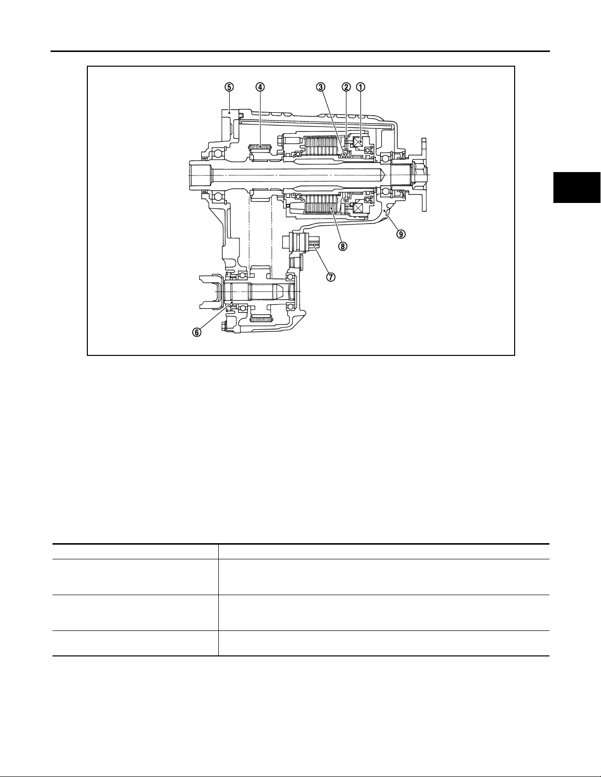
JSDIA0048ZZ
1. Electromagnet 2. Control clutch 3. Cam
4. Drive chain 5. Front case 6. Front drive shaft
7. AWD solenoid connector 8. Main clutch 9. Rear case
System Description INFOID:0000000000957227
DESCRIPTION
• Electronic control allows optimal distribution of torque to front/rear wheels to match road conditions.
• Makes possible stable driving, with no wheel spin, on snowy roads or other slippery surfaces.
• On roads which do not require AWD, it contributes to improved fuel economy by driving in conditions close to
rear-wheel drive.
• Sensor inputs determine the vehicle's turning condition, and in response tight cornering/braking are controlled by distributing optimum torque to front wheels.
• It transmits/receives each signal from the following control unit via CAN communication line.
Component parts Function
Transmits the following signals via CAN communication to AWD control unit.
ABS actuator and electric unit (control unit)
ECM
Unified meter and A/C amp.
NOTE:
• When driving, if there is a large difference between front and rear wheel speed which continues for a long
time, fluid temperature of drive system parts becomes too hi gh and AWD warning lamp blinks quickly. (When
AWD warning lamp blinks, vehicle changes to rear-wheel drive conditions.) Also, optional distribution of
torque sometimes becomes rigid before lamp blinks quickly, but it is not malfunction.
• If AWD warning lamp is blinking quickly, stop vehicle and allow it to idle for some time. Blinking will stop and
AWD system will be restored.
• Vehicle speed signal
• Stop lamp switch signal (brake signal)
Transmits the following signals via CAN communication to AWD control unit.
• Accelerator pedal position sign al
• Engine speed signal
Transmits conditions of parking brake switch via CAN communication to AWD control
unit.
H
I
J
K
L
M
N
O
P
DLN-9
Page 10
AWD SYSTEM
Revision: October 2006
2007 G35 Sedan
< FUNCTION DIAGNOSIS >
• When driving, AWD warning lamp may blink slowly if there is a significant difference in diameter of the tires.
At this time, vehicle performance is not fully available and cautious driving is required. (Continues until
engine is turned OFF.)
• If the warning lamp blinks slowly during driving but remains OFF after engine is restarted, the system is normal. If it again blinks slowly after driving for some time, vehicle must be inspected.
• When the difference of revolution speed between the front and rear wheel the shift occasionally changes to
direct 4-wheel driving conditions automatically. This is not malfunction.
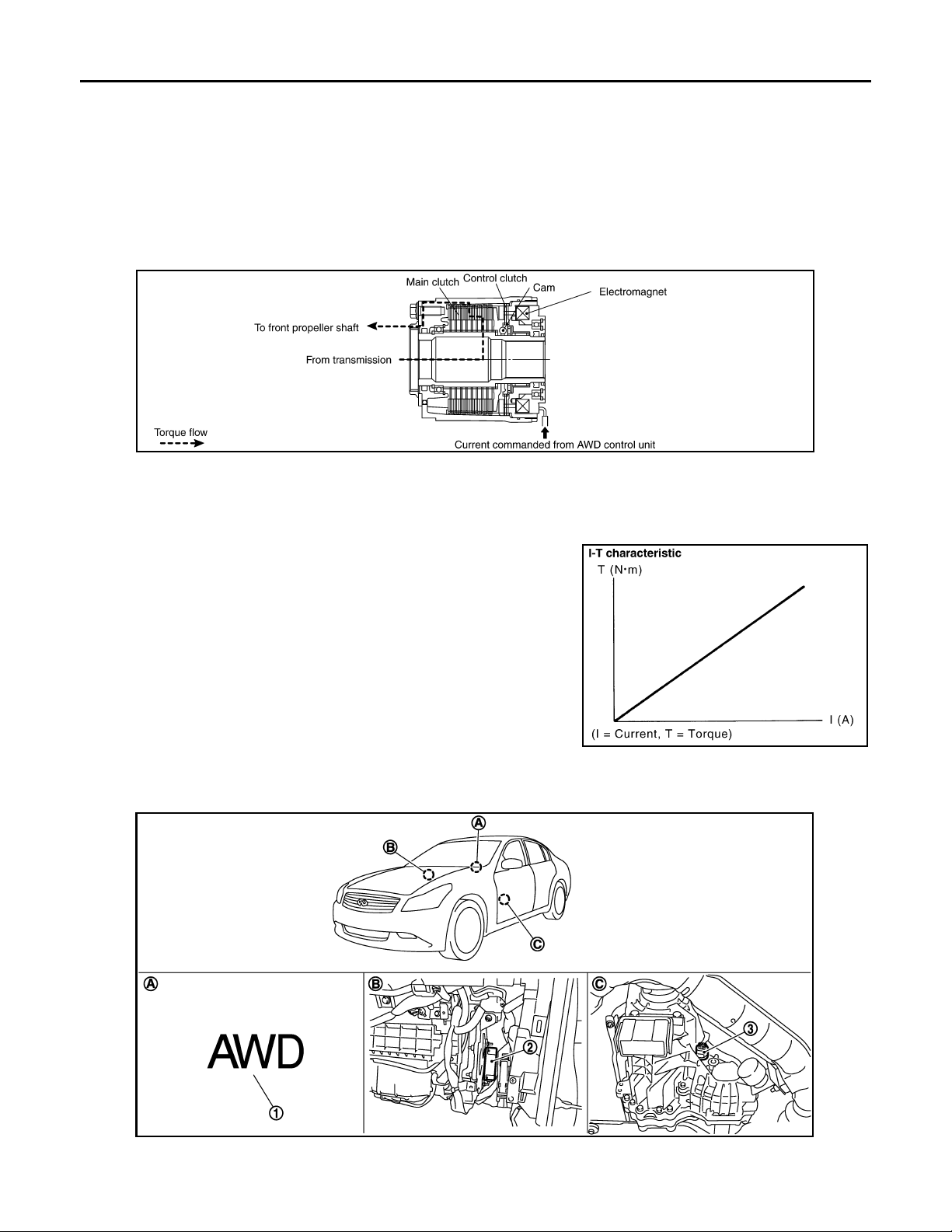
OPERATION PRINCIPLE
ELECTRIC CONTROLLED COUPLING
1. AWD control unit supplies command current to electric controlled coupling (AWD solenoid).
2. Control clutch is engaged by electromagnet and torque is detected in control clutch.
3. The cam operates in response to control clutch torque and applies pressure to main clutch.
4. Main clutch transmits torque to front wheels according to pressing power.
• Transmission torque to front wheels is determined according
to command current.
[TRANSFER: ETX13B]
SDIA2270E
SDIA1844E
Component Parts Location INFOID:0000000000957228
JSDIA0049ZZ
1. AWD warning lamp 2. AWD control unit 3. AWD solenoid harne ss connector
DLN-10
Page 11
AWD SYSTEM
Revision: October 2006
2007 G35 Sedan
< FUNCTION DIAGNOSIS >
A. Combination meter B. Glove box assembly removed C. Transfer assembly
[TRANSFER: ETX13B]
Component Description INFOID:0000000000957229
A
Component parts Reference/Function
AWD control unit DLN-14, "
Wheel sensors Detects wheel speed.
AWD solenoid DLN-16, "
Electric controlled coupling Transmits driving force to front final drive.
AWD warning lamp DLN-25, "
ABS actuator and electric unit (control unit) DLN-15, "Description"
ECM DLN-20, "Description"
Unified meter and A/C amp.
Transmits conditions o f parking brake switch vi a CAN communic ation to AWD control unit.
Description"
Description"
Description"
B
C
DLN
E
F
G
H
I
K
M
N
O
P
J
L
DLN-11
Page 12
DIAGNOSIS SYSTEM (AWD CONTROL UNIT)
Revision: October 2006
2007 G35 Sedan
< FUNCTION DIAGNOSIS >
[TRANSFER: ETX13B]
DIAGNOSIS SYSTEM (AWD CONTROL UNIT)
CONSULT-III Function (ALL MODE AWD/4WD) INFOID:0000000000957230
FUNCTION
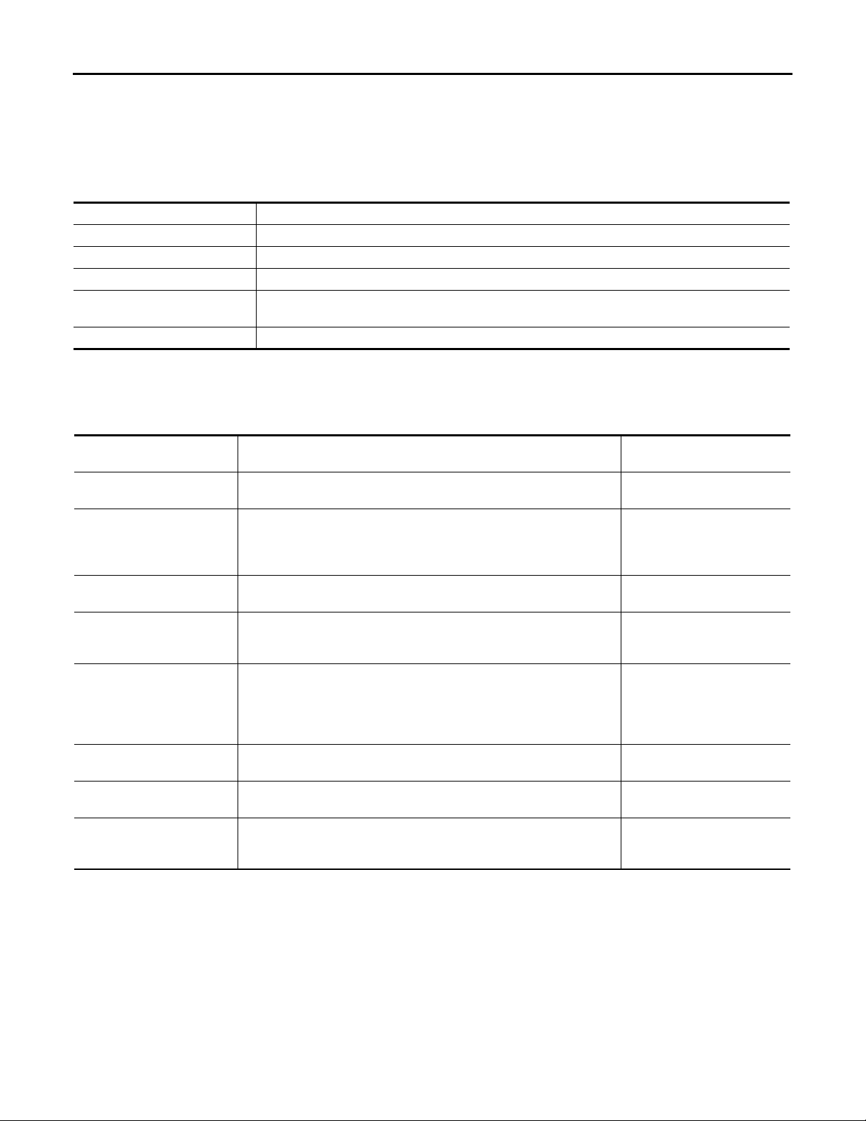
CONSULT-III can display each diagnostic item using the diagnostic test modes shown following.
Diagnostic test mode Function
Self-diagnostic results • Self-diagnostic results can be read and erased quickly.
Data monitor • Input/Output data in the AWD control unit can be read.
CAN diagnostic support monitor • The results of transmit/receive diagnosis of CAN communication can be read.
Active test
ECU part number • AWD control unit part number can be read.
SELF-DIAG RESULT MODE
• Drive at 30 km/h or more for approximately 1 minute before performing the self-diagnosis.
Display Item List
• Diagnostic Test Mode in which CONSULT-III drives some actuators apart from the AWD control
unit and also shifts some parameters in a specified range.
Items
(CONSULT-III screen terms)
CONTROLLER FAILURE
[C1201]
ABS SYSTEM
[C1203]
4WD SOLENOID
[C1204]
4WD ACTUATOR RLY
[C1205]
ENGINE SIGNAL 1
[C1210]
CAN COMM CIRCUIT
[U1000]
CONTROL UNIT (CAN)
[U1010]
NO DTC IS DETECTED.
FURTHER TESTING MAY
BE REQUIRED.
CAUTION:
• If “CAN COMM CIRCUIT [U1000]” or “CONTROL UNIT (CAN) [U1010]” is displayed with other DTCs, first perform the trouble
diagnosis for CAN communication line.
• Make sure that ABS warning lamp turns OFF by drivin g for a m inu te at v ehi cle s pee d of 30 km /h (1 9 MPH ) or m ore a fter turning ignition switch OFF if AWD warning lamp turns ON with system malfunction of “ABS SYSTEM [C1203]”. AWD warning
lamp may not turn OFF if it is normal unless ignition switch turns OFF at once and engine restarts after that.
Malfunction has occurred inside AWD control unit.
Malfunction related to wheel sensor has been detected by ABS actuator and electric unit (control unit).
Malfunction related to AWD solenoid ha s been detected.
Malfunction has been detected from AWD actuator relay integrated with
AWD control unit , or malfunc tion related to A WD solenoid has been detected.
Malfunction has been detected from ECM.
When AWD control unit is not transmitting or receiving CAN communication signal for 2 seconds or more.
When detecting error during the initial diagnosis of CAN controller of
AWD control unit.
No NG item has been detected. —
Diagnostic item is detected when... Possible cause
Internal malfunction of AWD
control unit
ABS malfunction
• Vehicle speed signal error
• Stop lamp switch signal
(brake signal) error
Internal malfunction of electronic controlled coupling
Internal malfunction of AWD
control unit
Malfunction of engine control
system
• Accelerator pedal position
signal error
• Engine speed signal error
CAN communication line error
AWD control unit error
How to Erase Self-Diagnostic Results
• Before erasing DTC memory, start the engine and drive at 30 km/h or more for approximately 1 minute.
Check that ABS warning lamp turns OFF.
NOTE:
Make sure that ABS warning lamp turns OFF by driving for a minute at vehicle speed of 30 km/h (19 MPH)
or more after turning ignition switch OFF if AWD warning lamp turns ON with system malfunction of “ABS
DLN-12
Page 13
DIAGNOSIS SYSTEM (AWD CONTROL UNIT)
Revision: October 2006
2007 G35 Sedan
< FUNCTION DIAGNOSIS >
SYSTEM [C1203]”. AWD warning lamp may not turn OFF if it is normal unless ignition switch turns OFF at
once and engine restarts after that.
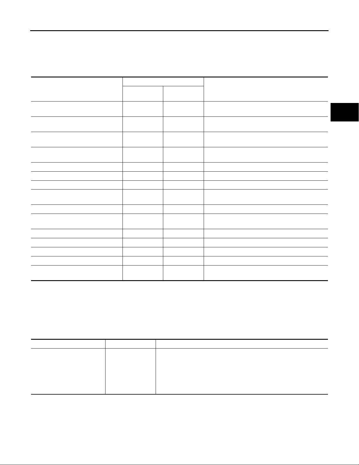
DATA MONITOR MODE
[TRANSFER: ETX13B]
A
Display Item List
×: Standard ❏: Optional item
Monitor Menu
Monitor item (Unit)
FR RH SENSOR [km/h] or [mph] ××
FR LH SENSOR [km/h] or [mph] ××
RR RH SENSOR [km/h] or [mph] ××
RR LH SENSOR [km/h] or [mph] ××
BATTERY VOLT [V] ❏❏Power supply voltage for AWD control unit
THRTL POS SEN [%] ❏❏Throttle opening status is displayed.
ETS SOLENOID [A] ❏❏Monitored value of current at A WD solenoid
STOP LAMP SW [On/Off] ❏❏
ENG SPEED SIG [Run/Stop] ❏❏Engine status is displayed.
ETS ACTUATOR [On/Off] ❏❏
4WD WARN LAMP [On/Off] ❏❏Control status of AWD warning lamp is displayed.
4WD MODE SW [AUTO] ❏❏Mode switch is not equipped, but displayed.
4WD MODE MON [AUTO] ❏❏Control status of AWD is displayed.
DIS-TIRE MONI [mm] ❏❏Improper size tire installed condition is displayed.
P BRAKE SW [On/Off] ❏❏
ECU INPUT
SIGNALS
MAIN
SIGNALS
Wheel speed calculated by front wheel sensor RH signal is displayed.
Wheel speed calculated by front wheel sensor LH signal is displayed.
Wheel speed calculated by rear wheel sensor RH signal is displayed.
Wheel speed calculated by rear wheel sensor LH signal is displayed.
Stop lamp switch signal status via CAN communication
line is displayed.
Operating condition of AWD actuator relay (integrated
in AWD control unit) is displayed.
Parking switch signal status via CAN communication
line is displayed.
Remarks
B
C
DLN
E
F
G
H
I
J
K
ACTIVE TEST MODE
Description
• Use this mode to determine and identify the details of a malfunction based on self-diagnostic results or data
monitor . AWD control unit gives drive signal to actuator with receiving command from CONSULT-III to check
operation of actuator.
Test Item
ETS S/V
(Detects AWD solenoid)
CAUTION:
Never continuously energize for a long time.
Test item Condition Description
• Change command current value to AWD solenoid, and then change driving
mode. (Monitor value is normal if it is within approximately ±10% of com-
• Vehicle stopped
• Engine running
• No DTC detected
mand value.)
Qu: Increase current value in increments of 0.20 A
Qd: Decrease current value in increments of 0.20 A
UP: Increase current value in increments of 0.02 A
DOWN: Decrease current value in increments of 0.02 A
DLN-13
L
M
N
O
P
Page 14
C1201 AWD CONTROL UNIT
Revision: October 2006
2007 G35 Sedan
< COMPONENT DIAGNOSIS >
[TRANSFER: ETX13B]
COMPONENT DIAGNOSIS
C1201 AWD CONTROL UNIT
Description INFOID:0000000000957231
• Controls driving force distribution by signals from each sensor from rear wheel driving mode (0:100) to AWD
mode (50:50).
• 2WD mode is available by fail-safe function if malfunction is detected in AWD system.
DTC Logic INFOID:0000000000957232
DTC DETECTION LOGIC
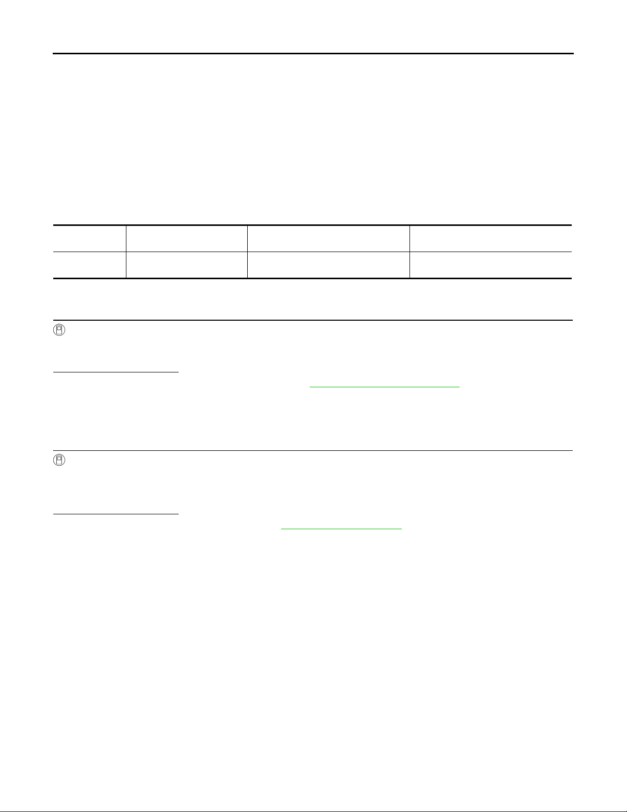
DTC
C1201 CONTROLLER FAILURE
(CONSULT-III screen terms)
Items
Diagnostic item is detected when... Possible cause
Malfunction has occurred inside AWD
control unit.
Internal malfunction of AWD control unit
DTC CONFIRMATION PROCEDURE
1.DTC REPRODUCTION PROCEDURE
With CONSULT-III
1. Turn the ignition switch OFF to ON.
2. Perform the self-diagnosis.
Is DTC
“C1201” detected?
YES >> Proceed to diagnosis procedure. Refer to DLN-14, "Diagnosis Procedure".
NO >> INSPECTION END
Diagnosis Procedure INFOID:0000000000957233
1.PERFORM SELF-DIAGNOSIS
With CONSULT-III
1. Erase AWD control unit self-diagnosis results.
2. Wait 10 minutes or more after turning the ignition switch OFF.
3. Perform the self-diagnosis again.
Is DTC
“C1201” detected?
YES >> Replace AWD control unit. Refer to DLN-49, "Exploded View".
NO >> Check AWD control unit pin terminals for damage or loose connection with harness connector. If
any items are damaged, repair or replace damaged parts.
DLN-14
Page 15
C1203 ABS ACTUATOR AND ELECTRIC UNIT (CONTROL UNIT)
Revision: October 2006
2007 G35 Sedan
< COMPONENT DIAGNOSIS >
[TRANSFER: ETX13B]
C1203 ABS ACTUATOR AND ELECTRIC UNIT (CONTROL UNIT)
Description INFOID:0000000000957234
Transmits the following signals via CAN communication to AWD control unit.
• Vehicle speed signal
• Stop lamp switch signal (brake signal)
DTC Logic INFOID:0000000000957235
DTC DETECTION LOGIC
DTC
C1203 ABS SYSTEM
(CONSULT-III screen terms)
DTC CONFIRMATION PROCEDURE
Items
Diagnostic item is detected when... Possible cause
Malfunction related to whee l sensor has
been detected by ABS actuator and
electric unit (control unit).
ABS malfunction
• Vehicle speed signal error
• Stop lamp switch signal (brake signal)
error
1.DTC REPRODUCTION PROCEDURE
With CONSULT-III
1. Start engine and drive at 30 km/h (19 MPH) or more for approx. 1 minute.
2. Perform the self-diagnosis.
Is DTC
Diagnosis Procedure INFOID:0000000000957236
“C1203” detected?
YES >> Proceed to diagnosis procedure. Refer to DLN-15, "Diagnosis Procedure".
NO >> INSPECTION END
A
B
C
DLN
E
F
G
H
I
1.ABS ACTUATOR AND ELECTRIC UNIT (CONTROL UNIT) SELF-DIAGNOSIS
With CONSULT-III
Perform self-diagnosis with ABS actuator and electric unit (control unit).
Is any malfunction detected by self-diagnosis?
YES >> Check the malfunctioning system.
NO >> GO TO 2.
2.AWD CONTROL UNIT SELF-DIAGNOSIS
With CONSULT-III
1. Erase AWD control unit self-diagnosis results.
2. Start engine and drive vehicle at 30 km/h (19 MPH) for at least 1 minute.
3. Make sure that ABS warning lamp turns OFF.
4. Perform self-diagnosis of AWD control unit.
Is DTC
“C1203” detected?
YES >> Replace AWD control. Refer to DLN-49, "Exploded View".
NO >> Check AWD control unit pin terminals for damage or loose connection with harness connector. If
any items are damaged, repair or replace damaged parts.
J
K
L
M
N
O
P
DLN-15
Page 16
C1204 AWD SOLENOID
Revision: October 2006
2007 G35 Sedan
< COMPONENT DIAGNOSIS >
[TRANSFER: ETX13B]
C1204 AWD SOLENOID
Description INFOID:0000000000957237
• Controls electric controlled coupling by command current from AWD control unit.
DTC Logic INFOID:0000000000957238
DTC DETECTION LOGIC
DTC
C1204 4WD SOLENOID
(CONSULT-III screen terms)
Items
Diagnostic item is detected when... Possible cause
Malfunction related to AWD solenoid has
been detected.
Internal malfunction of electronic controlled coupling
DTC CONFIRMATION PROCEDURE
1.DTC REPRODUCTION PROCEDURE
With CONSULT-III
1. Turn the ignition switch OFF to ON.
2. Perform the self-diagnosis.
Is DTC
“C1204” detected?
YES >> Proceed to diagnosis procedure. Refer to DLN-16, "Diagnosis Procedure".
NO >> INSPECTION END
Diagnosis Procedure INFOID:0000000000957239
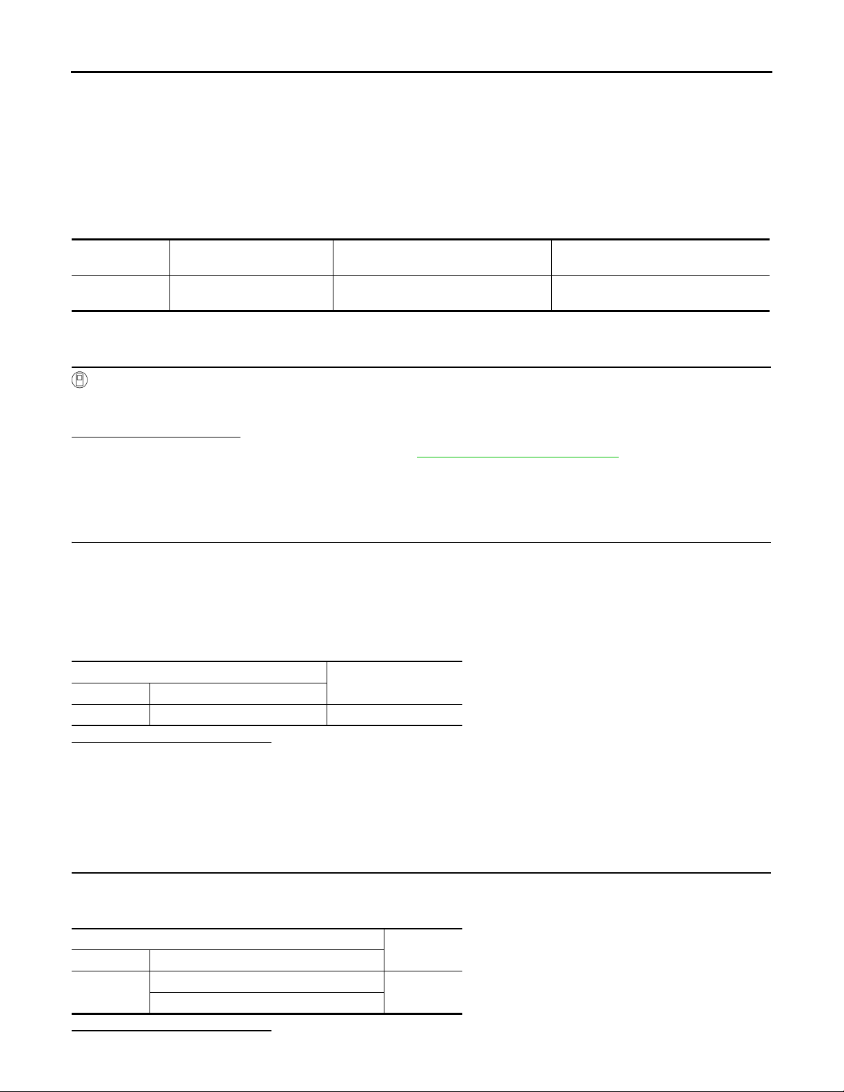
1.AWD SOLENOID VALVE POWER SUPPLY INSPECTION
1. Turn the ignition switch OFF.
2. Disconnect AWD control unit harness connector.
3. Turn the ignition switch ON.
CAUTION:
Never start the engine.
4. Check the voltage between AWD control unit harness connector and ground.
AWD control unit
Connector Terminal
F108 9 – Ground Battery voltage
Is the inspection result normal?
YES >> GO TO 2.
NO >> Check the following. If any items are damaged, repair or replace damaged parts.
• 10A fuse (#33) open
- Short among 10A fuse (#33) connector, AWD control unit harness connector No. 9 terminal and
the ground
- Open between the battery and AWD control unit harness connector No. 9 terminal
Voltage (Approx.)
2.AWD SOLENOID VALVE GROUND INSPECTION
1. Turn the ignition switch OFF.
2. Check the continuity between AWD control unit harness connector and ground.
AWD control unit
Connector Terminal
F108
Is the inspection result normal?
YES >> GO TO 3.
10 – Ground
11 – Ground
Continuity
Existed
DLN-16
Page 17
C1204 AWD SOLENOID
Revision: October 2006
2007 G35 Sedan
< COMPONENT DIAGNOSIS >
NO >> Repair or replace damaged parts.
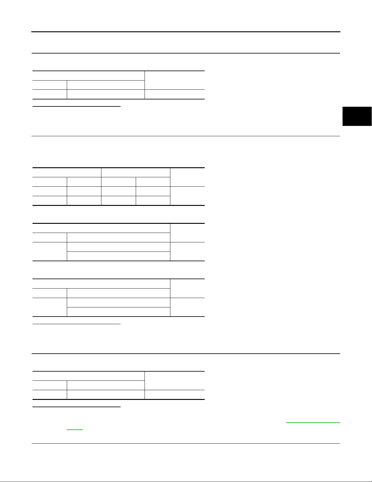
3.CHECK AWD SOLENOID CIRCUIT (1)
Check the resistance between AWD control unit harness connector terminals.
AWD control unit
Connector Terminal
F108 1 – 2 2.45 Ω
Resistance (Approx.)
Is the inspection result normal?
YES >> GO TO 5.
NO >> GO TO 4.
4.CHECK AWD SOLENOID CIRCUIT (2)
[TRANSFER: ETX13B]
A
B
C
DLN
1. Disconnect AWD solenoid harness connector.
2. Check the continuity between AWD control unit harness connector and AWD solenoid harness connector
terminals.
AWD control unit AWD solenoid
Connector Terminal Connector Terminal
F108 1 F57 1
F108 2 F57 2
Continuity
Existed
3. Check the continuity between AWD control unit harness connector and the ground.
AWD control unit
Connector Terminal
F108
1 – Ground
2 – Ground
Continuity
Not existed
4. Check the continuity between AWD solenoid harness connector and the ground.
AWD solenoid
Connector Terminal
F57
1 – Ground
2 – Ground
Continuity
Not existed
Is the inspection result normal?
YES >> GO TO 5.
NO >> Repair or replace damaged parts.
5.CHECK AWD SOLENOID
E
F
G
H
I
J
K
L
M
Check the resistance between AWD solenoid harness connector terminals.
Connector Terminal
F57 1 – 2 2.45 Ω
Is the inspection result normal?
YES >> GO TO 6.
NO >> AWD solenoid is malfunctioning. Replace electric controlled coupling. Refer to DLN-69, "
6.CHECK TERMINALS AND HARNESS CONNECTORS
1. Check AWD control unit pin terminals for damage or loose connection with harness connector.
2. Check AWD solenoid pin terminals for damage or loose connection with harness connector.
AWD solenoid
View".
Resistance (Approx.)
DLN-17
N
O
P
Exploded
Page 18
C1204 AWD SOLENOID
Revision: October 2006
2007 G35 Sedan
< COMPONENT DIAGNOSIS >
Is the inspection result normal?
YES >> Replace AWD control unit. Refer to DLN-49, "Exploded View".
NO >> Repair or replace damaged parts.
[TRANSFER: ETX13B]
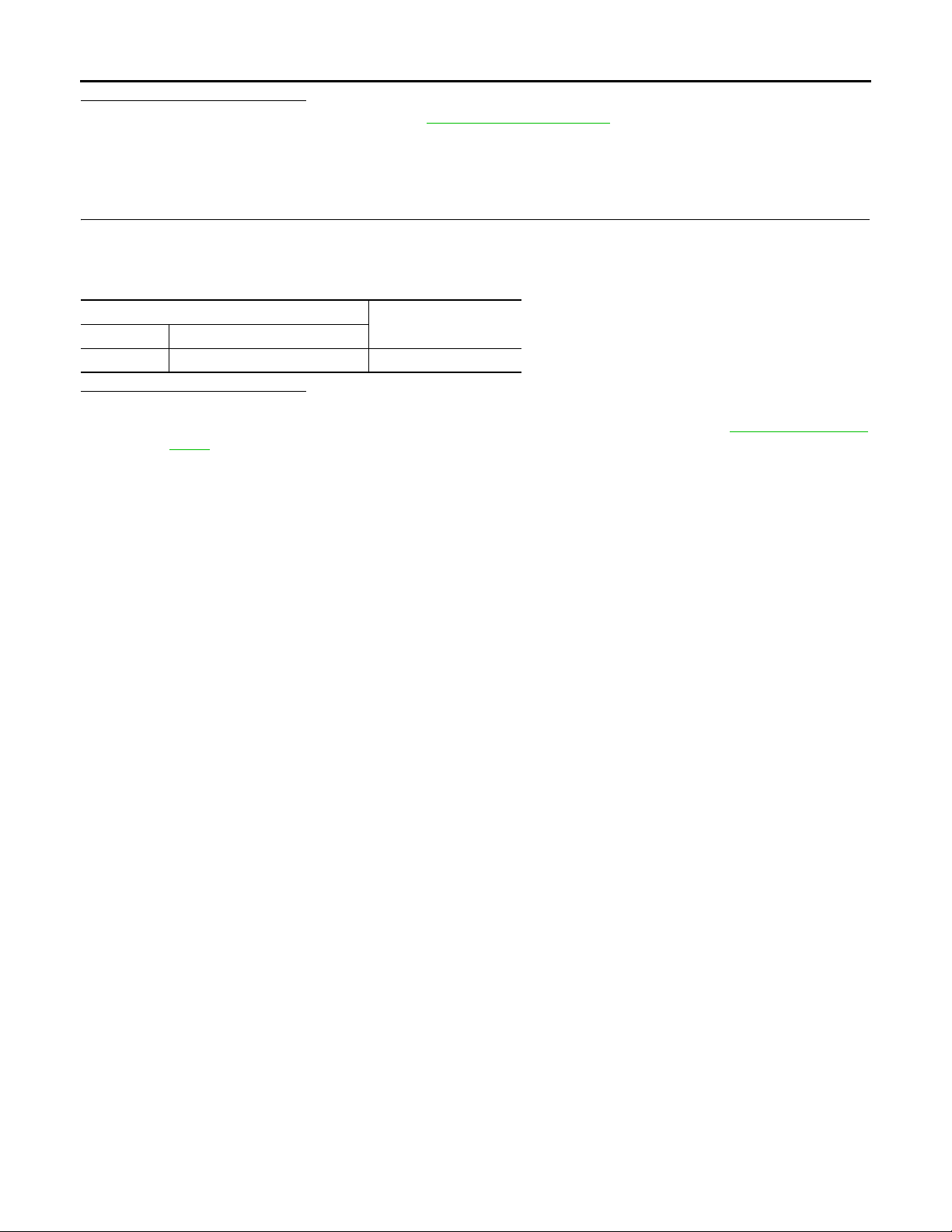
Component Inspection INFOID:0000000000957240
1.CHECK AWD SOLENOID
1. Turn the ignition switch OFF.
2. Disconnect AWD solenoid harness connector.
3. Check the resistance between AWD solenoid harness connector terminals.
AWD solenoid
Connector Terminal
F57 1 – 2 2.45 Ω
Is the inspection result normal?
YES >> INSPECTION END
NO >> AWD solenoid is malfunctioning. Replace electric controlled coupling. Refer to DLN-69, "
View".
Resistance (Approx.)
Exploded
DLN-18
Page 19
< COMPONENT DIAGNOSIS >
Revision: October 2006
2007 G35 Sedan
C1205 AWD ACTUATOR RELAY
[TRANSFER: ETX13B]
C1205 AWD ACTUATOR RELAY
Description INFOID:0000000000957241
• AWD solenoid is supplied with voltage by the internal circuit of AWD control unit.
DTC Logic INFOID:0000000000957242
DTC DETECTION LOGIC
DTC
C1205 4WD ACTUATOR RLY
(CONSULT-III screen terms)
DTC CONFIRMATION PROCEDURE
Items
Diagnostic item is detected when... Possible cause
Malfunction has been detected from
AWD actuator relay integrate d with AWD
control unit, or malfunction related to
AWD solenoid has been detected.
Internal malfunction of AWD control unit
1.DTC REPRODUCTION PROCEDURE
With CONSULT-III
1. Turn the ignition switch OFF to ON.
2. Perform the self-diagnosis.
Is DTC
“C1205” detected?
YES >> Proceed to diagnosis procedure. Refer to DLN-19, "Diagnosis Procedure".
NO >> INSPECTION END
A
B
C
DLN
E
F
G
H
Diagnosis Procedure INFOID:0000000000957243
1.PERFORM SELF-DIAGNOSIS
With CONSULT-III
1. Erase AWD control unit self-diagnosis results.
2. Wait 10 minutes or more after turning the ignition switch OFF.
3. Perform self-diagnosis of AWD control unit.
Is DTC
“C1205” detected?
YES >> Replace AWD control. Refer to DLN-49, "Exploded View".
NO >> Check AWD control unit pin terminals for damage or loose connection with harness connector. If
any items are damaged, repair or replace damaged parts.
I
J
K
L
M
N
O
P
DLN-19
Page 20
C1210 ECM
Revision: October 2006
2007 G35 Sedan
< COMPONENT DIAGNOSIS >
[TRANSFER: ETX13B]
C1210 ECM
Description INFOID:0000000000957244
• Transmits the following signals via CAN communication to AWD control unit.
- Accelerator pedal position signal
- Engine speed signal
DTC Logic INFOID:0000000000957245
DTC DETECTION LOGIC
DTC
C1210 ENGINE SIGNAL 1
(CONSULT-III screen terms)
Items
Diagnostic item is detected when... Possible cause
Malfunction has been detected from
ECM.
Malfunction of engine control system
• Accelerator pedal position signal e rror
• Engine speed signal error
DTC CONFIRMATION PROCEDURE
1.DTC REPRODUCTION PROCEDURE
With CONSULT-III
1. Start the engine. Drive the vehicle for a while.
2. Perform the self-diagnosis.
Is DTC
“C1210” detected?
YES >> Proceed to diagnosis procedure. Refer to DLN-20, "Diagnosis Procedure".
NO >> INSPECTION END
Diagnosis Procedure INFOID:0000000000957246
1.ECM SELF-DIAGNOSIS
With CONSULT-III
Perform self-diagnosis of ECM.
Is any malfunction detected by self-diagnosis?
YES >> Check the malfunctioning system.
NO >> GO TO 2.
2.AWD CONTROL UNIT SELF-DIAGNOSIS
With CONSULT-III
1. Erase AWD control unit self-diagnosis results.
2. Turn the ignition switch OFF.
3. Start the engine. Drive the vehicle for a while.
4. Make sure that malfunction indicator lamp (MIL) turns OFF.
5. Stop the vehicle. Perform AWD control unit self-diagnosis.
Is DTC
“C1210” detected?
YES >> Replace AWD control. Refer to DLN-49, "Exploded View".
NO >> Check AWD control unit pin terminals for damage or loose connection with harness connector. If
any items are damaged, repair or replace damaged parts.
DLN-20
Page 21
< COMPONENT DIAGNOSIS >
Revision: October 2006
2007 G35 Sedan
U1000 CAN COMM CIRCUIT
[TRANSFER: ETX13B]
U1000 CAN COMM CIRCUIT
Description INFOID:0000000000957247
• CAN (Controller Area Network) is a serial communication line for real time application. It is an on-vehicle
multiplex communication line with high data communication speed and excellent error detection ability . Many
electronic control units are equipped onto a vehicle, and each control unit shares information and links with
other control units during operation (not independent). In CAN communication, control units are connected
with 2 communication lines (CAN-H line, CAN-L line) allowing a high rate of information transmission with
less wiring. Each control unit transmits/receives data but selectively reads required data only.
DTC Logic INFOID:0000000000957248
DTC DETECTION LOGIC
DTC
U1000 CAN COMM CIRCUIT
(CONSULT-III screen terms)
DTC CONFIRMATION PROCEDURE
Items
Diagnostic item is detected when... Possible cause
When AWD control unit is not transmitting or receiving CAN communication
signal for 2 seconds or more.
CAN communication line error
1.DTC REPRODUCTION PROCEDURE
With CONSULT-III
1. Turn the ignition switch OFF to ON.
2. Perform the self-diagnosis.
Is DTC
“U1000” detected?
YES >> Proceed to diagnosis procedure. Refer to DLN-21, "Diagnosis Procedure".
NO >> INSPECTION END
A
B
C
DLN
E
F
G
H
I
Diagnosis Procedure INFOID:0000000000957249
1.PERFORM SELF-DIAGNOSIS
With CONSULT-III
Perform self-diagnosis of AWD control unit.
Is DTC
“U1000” detected?
YES >> CAN specification chart.
NO >> INSPECTION END
J
K
L
M
N
O
P
DLN-21
Page 22
U1010 CONTROL UNIT (CAN)
Revision: October 2006
2007 G35 Sedan
< COMPONENT DIAGNOSIS >
[TRANSFER: ETX13B]
U1010 CONTROL UNIT (CAN)
Description INFOID:0000000000957250
• CAN (Controller Area Network) is a serial communication line for real time application. It is an on-vehicle
multiplex communication line with high data communication speed and excellent error detection ability. Many
electronic control units are equipped onto a vehicle, and each control unit shares information and links with
other control units during operation (not independent). In CAN communication, control units are connected
with 2 communication lines (CAN-H line, CAN-L line) allowing a high rate of information transmission with
less wiring. Each control unit transmits/receives data but selectively reads required data only.
DTC Logic INFOID:0000000000957251
DTC DETECTION LOGIC
DTC
U1010 CONTROL UNIT (CAN)
(CONSULT-III screen terms)
Items
Diagnostic item is detected when... Possible cause
When detecting error during the initial d iagnosis of CAN controller of AWD control unit.
AWD control unit error
DTC CONFIRMATION PROCEDURE
1.DTC REPRODUCTION PROCEDURE
With CONSULT-III
1. Turn the ignition switch OFF to ON.
2. Perform the self-diagnosis.
Is DTC
“U1010” detected?
YES >> Proceed to diagnosis procedure. Refer to DLN-22, "Diagnosis Procedure".
NO >> INSPECTION END
Diagnosis Procedure INFOID:0000000000957252
1.AWD CONTROL UNIT INSPECTION
Check AWD control unit harness connector for disconnection and deformation.
Is the inspection result normal?
YES >> Replace AWD control unit. Refer to DLN-49, "Exploded View".
NO >> Repair or replace damaged parts.
DLN-22
Page 23
POWER SUPPLY AND GROUND CIRCUIT
Revision: October 2006
2007 G35 Sedan
< COMPONENT DIAGNOSIS >
[TRANSFER: ETX13B]
POWER SUPPLY AND GROUND CIRCUIT
Description INFOID:0000000000957253
• Supplies power to AWD control unit.
Diagnosis Procedure INFOID:0000000000957254
1.AWD CONTROL UNIT POWER SUPPLY INSPECTION
1. Turn the ignition switch OFF.
2. Disconnect AWD control unit harness connector.
3. Check the voltage between AWD control unit harness connector and ground.
AWD control unit
Connector Terminal
F108 7 – Ground 0 V
Voltage (Approx.)
4. Turn the ignition switch ON.
CAUTION:
Never start the engine.
5. Check the voltage between AWD control unit harness connector and ground.
AWD control unit
Connector Terminal
F108 7 – Ground Battery voltage
Voltage (Approx.)
Is the inspection result normal?
YES >> GO TO 2.
NO >> Check the following. If any items are damaged, repair or replace damaged parts.
• 10A fuse (#45) open
- Short among 10A fuse (#45) connector, AWD control unit harness connector No. 7 terminal and
the ground
- Open between the ignition switch and AWD control unit harness connector No. 7 terminal
2.AWD SOLENOID VALVE POWER SUPPLY INSPECTION
Check the voltage between AWD control unit harness connector and ground.
A
B
C
DLN
E
F
G
H
I
J
K
Connector Terminal
F108 9 – Ground Battery voltage
Is the inspection result normal?
YES >> GO TO 3.
NO >> Check the following. If any items are damaged, repair or replace damaged parts.
3.AWD SOLENOID VALVE GROUND INSPECTION
1. Turn the ignition switch OFF.
2. Check the continuity between AWD control unit harness connector and ground.
Connector Terminal
F108
AWD control unit
Voltage (Approx.)
• 10A fuse (#33) open
- Short among 10A fuse (#33) connector, AWD control unit harness connector No. 9 terminal and
the ground
- Open between the battery and AWD control unit harness connector No. 9 terminal
AWD control unit
10 – Ground
11 – Ground
Continuity
Existed
DLN-23
L
M
N
O
P
Page 24

POWER SUPPLY AND GROUND CIRCUIT
Revision: October 2006
2007 G35 Sedan
< COMPONENT DIAGNOSIS >
Is the inspection result normal?
YES >> INSPECTION END
NO >> Repair or replace damaged parts.
[TRANSFER: ETX13B]
DLN-24
Page 25
< COMPONENT DIAGNOSIS >
Revision: October 2006
2007 G35 Sedan
AWD WARNING LAMP
[TRANSFER: ETX13B]
AWD WARNING LAMP
Description INFOID:0000000000957255
• Turns ON when there is a malfunction in AWD system. It indicates that fail-safe mode is engaged and vehicle change to rear-wheel drive or shifting driving force-AWD (Front-wheels still have some driving torque).
• Also turns ON when ignition switch is turned ON, for purpose of lamp check. Turns OFF approximately for 1
second after the engine starts if system is normal.
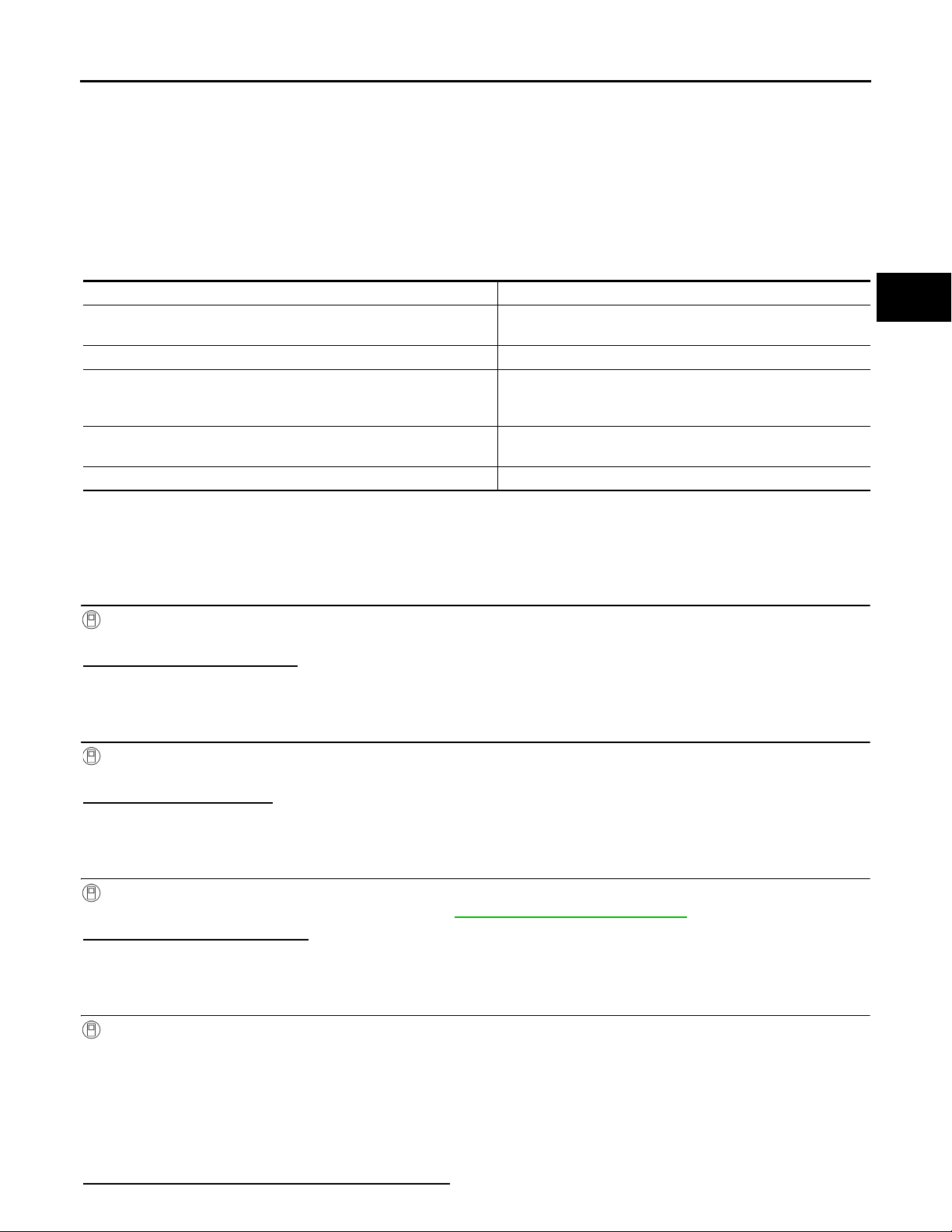
AWD WARNING LAMP INDICATION
Condition AWD warning lamp
Lamp check
AWD system malfunction ON
Protection function is activated due to heavy load to electric controlled
coupling. (AWD system is not malfunctioning and AWD system changes to 2WD mode.)
Large difference in diameter of front/rear tires
Other than above (system normal) OFF
CAUTION:
AWD warning lamp also turns ON due to data reception error, CAN communication error etc.
Diagnosis Procedure INFOID:0000000000957256
Turns ON when ignition switch is turned ON. Turns OFF ap-
prox. 1 second after engine start.
Quick blinking: 2 times/second
(Blinking in approx. 1 minute and then turning OFF)
Slow blinking: 1 time/2 seconds
(Continuing to blink until turning ignition switch OFF)
A
B
C
DLN
E
F
G
H
1.UNIFIED METER AND A/C AMP. SELF-DIAGNOSIS
With CONSULT-III
Perform the self-diagnosis of the unified meter and A/C amp.
Is any error system detected?
YES >> Check the error system.
NO >> GO TO 2.
2.SELF-DIAGNOSIS STARTS
With CONSULT-III
Perform AWD control unit self-diagnosis.
Is DTC
“U1000” detected?
YES >> Check the error system.
NO >> GO TO 3.
3.COMBINATION METER CIRCUIT INSPECTION
With CONSULT-III
Perform the system diagnosis for “B2202”. Refer to MWI-44, "
Is the inspection result normal?
YES >> GO TO 4.
NO >> Repair or replace the specific malfunctioning part.
Diagnosis Procedure".
4.AWD WARNING LAMP INSPECTION
With CONSULT-III
1. Connect the unified meter and A/C amp. harness connector.
2. Connect the combination meter harness connector.
3. Disconnect AWD solenoid harness connector.
4. Turn the ignition switch ON.
CAUTION:
Never start the engine.
5. Check “4WD W/L” of AWD control unit CONSULT-III “DATA MONITOR”.
Does the item on
“DATA MONITOR” indicate “On”?
I
J
K
L
M
N
O
P
DLN-25
Page 26
AWD WARNING LAMP
Revision: October 2006
2007 G35 Sedan
< COMPONENT DIAGNOSIS >
YES >> GO TO 5.
NO >> Replace AWD control unit. Refer to DLN-49, "
Exploded View".
[TRANSFER: ETX13B]
5.COMBINATION METER POWER SUPPLY INSPECTION
With CONSULT-III
Perform the trouble diagnosis of the combination meter power supply. Refer to MWI-49, "
METER : Diagnosis Procedure".
Is the inspection result normal?
YES >> INSPECTION END
NO >> Repair or replace the specific malfunctioning part.
COMBINATION
DLN-26
Page 27
< ECU DIAGNOSIS >
Revision: October 2006
2007 G35 Sedan
AWD CONTROL UNIT
[TRANSFER: ETX13B]
ECU DIAGNOSIS
AWD CONTROL UNIT
Reference Value INFOID:0000000000957257
VALUES ON THE DIAGNOSIS TOOL
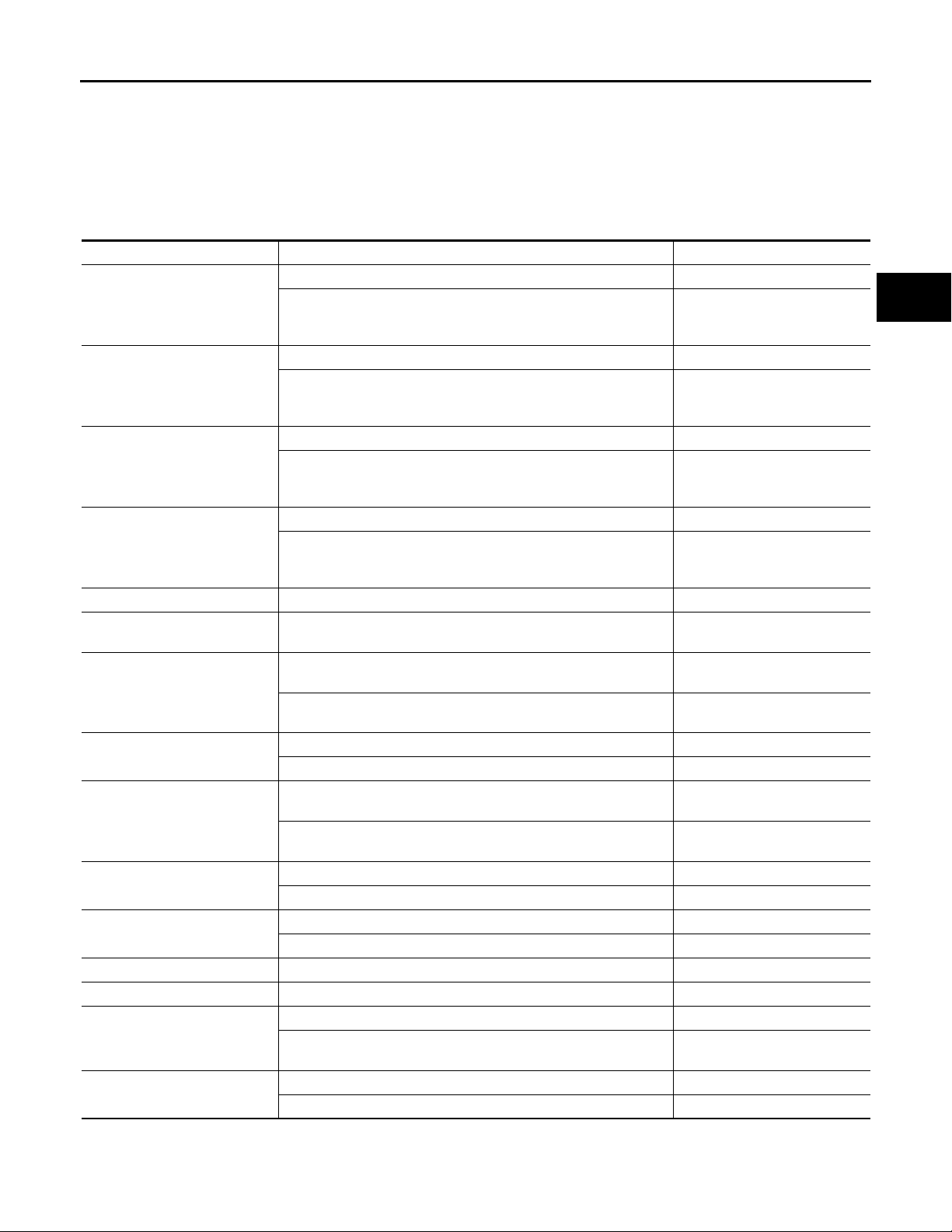
Monitor item Condition Value/Status
Vehicle stopped 0.00 km/h (0.00 mph)
FR RH SENSOR [km/h] or
[mph]
FR LH SENSOR [km/h] or
[mph]
RR RH SENSOR [km/h] or
[mph]
RR LH SENSOR [km/h] or
[mph]
BATTERY VOLT [V] Ignition switch: ON Battery voltage
THRTL POS SEN [%]
ETS SOLENOID [A]
STOP LAMP SW [ON/OFF]
ENG SPEED SIG [RUN/STOP]
ETS ACTUATOR [ON/OFF]
4WD WARN LAMP [ON/OFF]
4WD MODE SW [AUTO] Always AUTO
4WD MODE MON [AUTO] Engine running AUTO
DIS-TIRE MONI [mm]
P BRAKE SW [ON/OFF]
*: The values are changed by throttle opening and engine speed.
Vehicle running
CAUTION:
Check air pressure of tire under standard condition.
Vehicle stopped 0.00 km/h (0.00 mph)
Vehicle running
CAUTION:
Check air pressure of tire under standard condition.
Vehicle stopped 0.00 km/h (0.00 mph)
Vehicle running
CAUTION:
Check air pressure of tire under standard condition.
Vehicle stopped 0.00 km/h (0.00 mph)
Vehicle running
CAUTION:
Check air pressure of tire under standard condition.
When depressing accelerator pedal
(Value rises gradually in response to throttle position.)
Engine running
• At idle speed
Engine running
• When depressing accelerator pedal
Brake pedal: Depressed ON
Brake pedal: Released OFF
Engine stopped
(Engine speed: Less than 400 rpm)
Engine running
(Engine speed: 400 rpm or more)
Engine stopped (Ignition switch: ON) OFF
Engine running ON
AWD warning lamp: ON ON
AWD warning lamp: OFF OFF
Vehicle running with normal size tire installed 0 – 4 mm
Vehicle running with improper size tire installed (Front/rear tire size
difference, wear condition)
Parking brake operated ON
Parking brake not operated OFF
Approximately equal to the indication on speedometer (Insid e
of ±10%)
Approximately equal to the indication on speedometer (Insid e
of ±10%)
Approximately equal to the indication on speedometer (Insid e
of ±10%)
Approximately equal to the indication on speedometer (Insid e
of ±10%)
0 – 100 %
Approx. 0.000 A
Approx. 0.000 – 0.500 A*
STOP
RUN
4 – 8 mm, 8 – mm
A
B
C
DLN
E
F
G
H
I
J
K
L
M
N
O
P
TERMINAL LAYOUT
DLN-27
Page 28
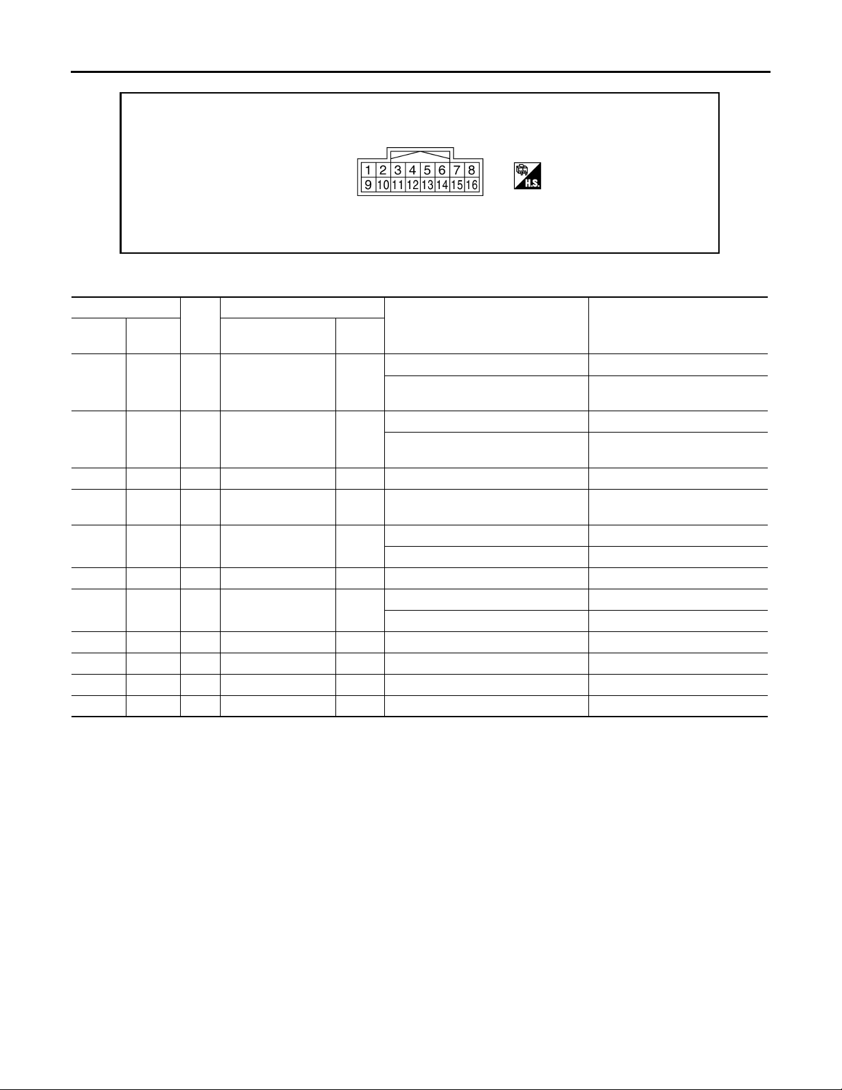
< ECU DIAGNOSIS >
Revision: October 2006
2007 G35 Sedan
PHYSICAL VALUES
AWD CONTROL UNIT
[TRANSFER: ETX13B]
JSDIA0057ZZ
Terminal No.
+ - Signal name
1GroundBR
2GroundY
4 Ground W Fluid temperature — — —
6GroundSB
7 Ground G Ignition switch Input
8GroundLCAN-H — — —
9GroundO
10 Ground B Ground — Always 0 V
11 Ground B Ground — Always 0 V
12 Ground LG Oil temperature — — —
16 Ground P CAN-L — — —
*: The values are changed by throttle opening and engine speed.
CAUTION:
When using circuit tester to measure voltage for inspection, be sure not to extend forcibly any connector terminals.
Wire
color
AWD solenoid power supply
AWD solenoid
ground
K-LINE (CONSULTIII signal)
Power supply (AWD
solenoid power)
Description
Input/
Output
Engine speed: At idle 2.5 V
Output
Input
Engine speed: 3,000 rpm or more
constant
Engine speed: At idle 0 V
—
Engine speed: 3,000 rpm or more
constant
—— —
Ignition switch: ON Battery voltage
Ignition switch: OFF 0 V
Ignition switch: ON Battery voltage
Ignition switch: OFF Battery voltage
Condition Value (Approx.)
8 V*
0 V
Wiring Diagram — AWD SYSTEM — INFOID:0000000000957258
DLN-28
Page 29
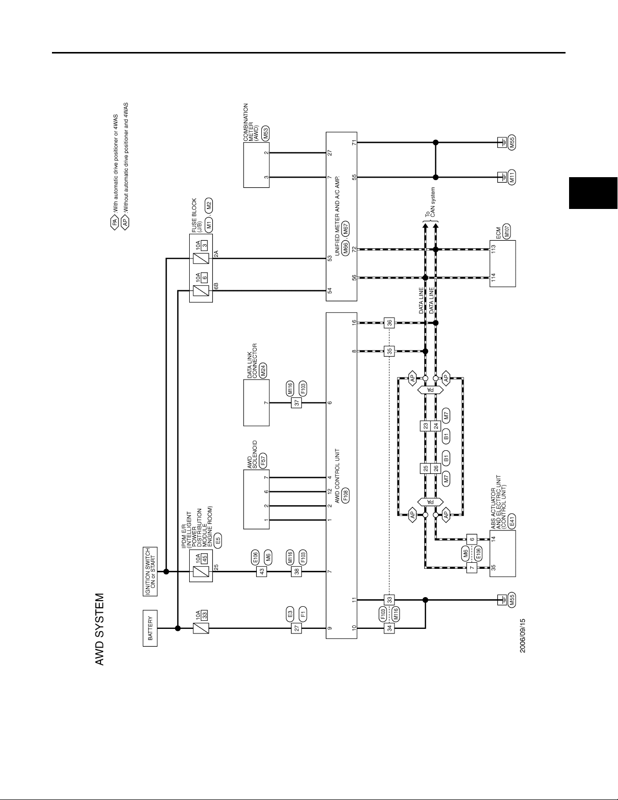
< ECU DIAGNOSIS >
B
Revision: October 2006
2007 G35 Sedan
AWD CONTROL UNIT
[TRANSFER: ETX13B]
A
B
C
DLN
E
F
G
H
K
M
N
O
I
J
L
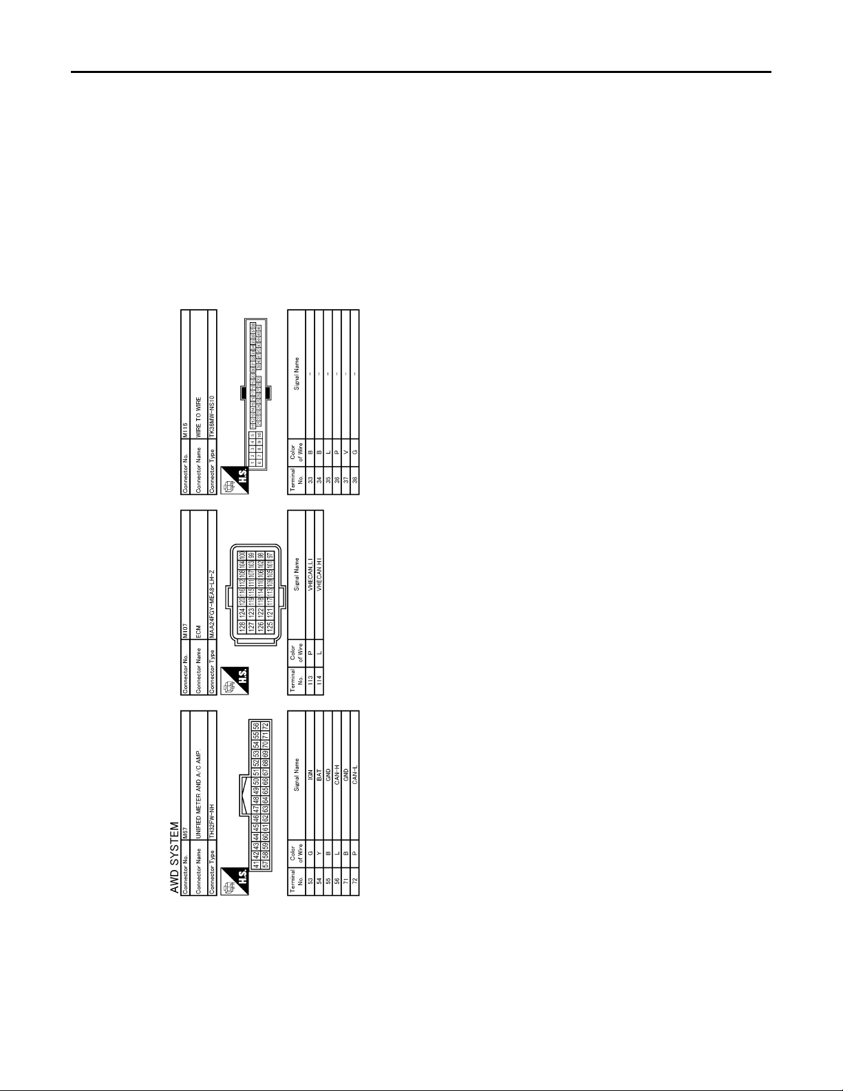
JCDWA0009G
P
DLN-29
Page 30
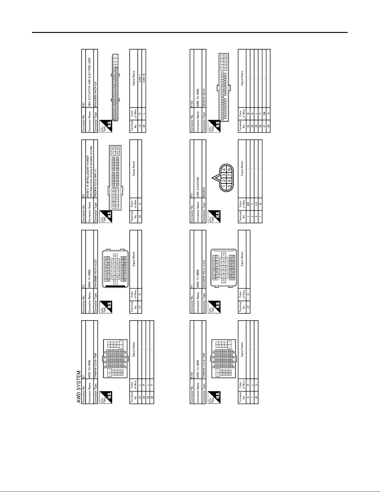
< ECU DIAGNOSIS >
B
Revision: October 2006
2007 G35 Sedan
AWD CONTROL UNIT
[TRANSFER: ETX13B]
JCDWA0010G
DLN-30
Page 31
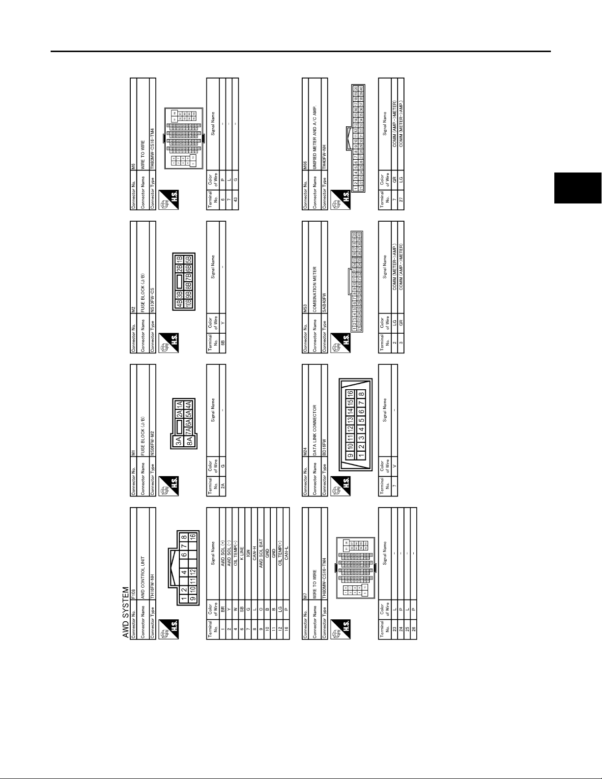
< ECU DIAGNOSIS >
B
Revision: October 2006
2007 G35 Sedan
AWD CONTROL UNIT
[TRANSFER: ETX13B]
A
B
C
DLN
E
F
G
H
K
M
N
O
I
J
L
JCDWA0011G
P
DLN-31
Page 32
< ECU DIAGNOSIS >
B
Revision: October 2006
2007 G35 Sedan
AWD CONTROL UNIT
[TRANSFER: ETX13B]
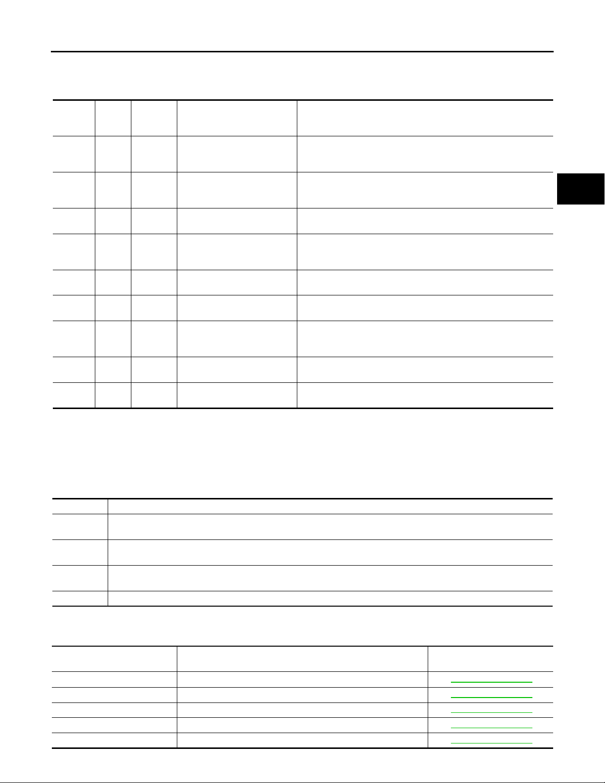
Fail Safe
AWD system
• If any malfunction occurs in AWD electrical system, and control unit detects the malfunction, AWD warning
lamp on combination meter turns ON to indicate system malfunction.
• When AWD warning lamp is ON, vehicle changes to rear-wheel drive or shifting driving force-AWD (Front-
wheels still have some driving torque).
JCDWA0012G
INFOID:0000000000957259
DLN-32
Page 33
AWD CONTROL UNIT
Revision: October 2006
2007 G35 Sedan
< ECU DIAGNOSIS >
• AWD system activates its protection function (shuts down AWD system temporarily) if AWD system detects
high load continuously or the front wheel tire size differs from the rear tire size. (AWD system is automatically restored if AWD system no longer detects any overload or the tire size difference is eliminated.)
[TRANSFER: ETX13B]
A
Warn-
Function
Protec-
tion
function
Protec-
tion
function
Fail-safe
function
Fail-safe
function
Fail-safe
function
Fail-safe
function
Fail-safe
function
Fail-safe
function
Fail-safe
function
*1: Quick blinking: 2 times/second (blinking in approx. 1 minute and then turning OFF)
*2: Slow blinking: 1 time/2 seconds (Continuing to blink until turning ignition switch OFF)
ing
lamp
Blink-
ing
Blink-
ing
ON C1201 AWD control unit Internal malfunction of AWD control unit
ON C1203
ON C1204 AWD solenoid Internal malfunction of electronic controlled coupling
ON C1205 AWD control unit Internal malfunction of AWD control unit
ON C1210 ECM
ON U1000 CAN communication line CAN communication line error
ON U1010 AWD control unit AWD control unit error
DTC No. Detected area (Error area) Error area and root cause
*1
*2
— AWD control unit
—
Outer diameters of front and
rear wheel tires
ABS actuator and electric unit
(control unit)
Transfer assembly in protection mode
(Internal temperature rise of electronic controlled coupling)
Malfunction in each tire or different tire diameter
ABS malfunction
• Vehicle speed signal error
• Stop lamp switch signal (brake signal) error
Malfunction of engine control system
• Accelerator pedal position signal error
• Engine speed signal error
B
C
DLN
E
F
G
H
I
J
DTC Inspection Priority Chart INFOID:0000000000957260
If some DTCs are displayed at the same time, perform inspections one by one based on the following priority
chart.
Priority Detected items (DTC)
1
2
3
4 • C1204 AWD SOLENOID VALVE
• U1000 CAN COMM CIRCUIT
• U1010 CONTROL UNIT (CAN)
• C1201 AWD CONTROL UNIT
• C1205 AWD ACTUATOR RELAY
• C1203 ABS ACTUATOR AND ELECTRIC UNIT (CONTROL UNIT)
• C1210 ECM
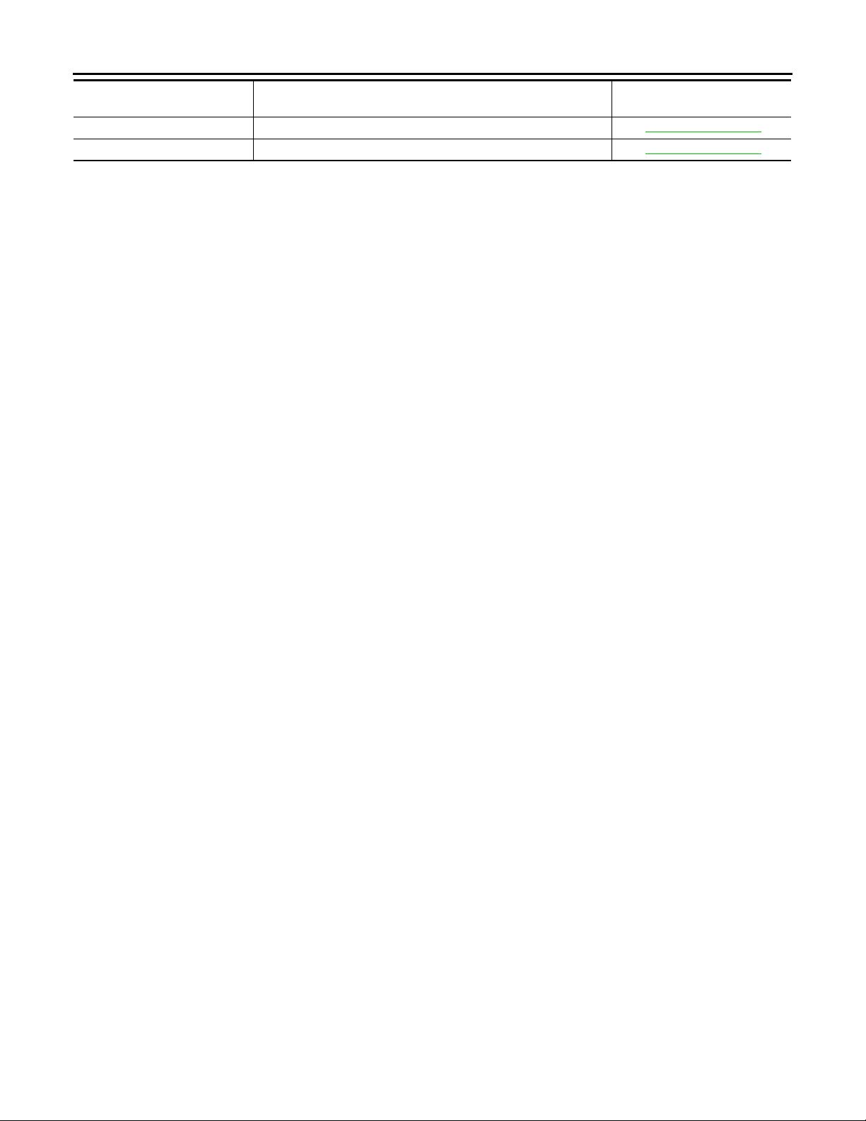
DTC Index INFOID:0000000000957261
DTC
C1201 CONTROLLER FAILURE DLN-14, "
C1203 ABS SYSTEM DLN-15, "Description"
C1204 4WD SOLENOID DLN-16, "Description"
C1205 4WD ACTUATOR RLY DLN-19, "Description"
C1210 ENGINE SIGNAL 1 DLN-20, "Description"
(CONSULT-III screen terms)
Items
Reference
Description"
K
L
M
N
O
P
DLN-33
Page 34
< ECU DIAGNOSIS >
Revision: October 2006
2007 G35 Sedan
AWD CONTROL UNIT
[TRANSFER: ETX13B]
DTC
U1000 CAN COMM CIRCUIT DLN-21, "Description"
U1010 CONTROL UNIT (CAN) DLN-22, "Description"
(CONSULT-III screen terms)
Items
Reference
DLN-34
Page 35
< SYMPTOM DIAGNOSIS >
Revision: October 2006
2007 G35 Sedan
AWD SYSTEM SYMPTOMS
[TRANSFER: ETX13B]
SYMPTOM DIAGNOSIS
AWD SYSTEM SYMPTOMS
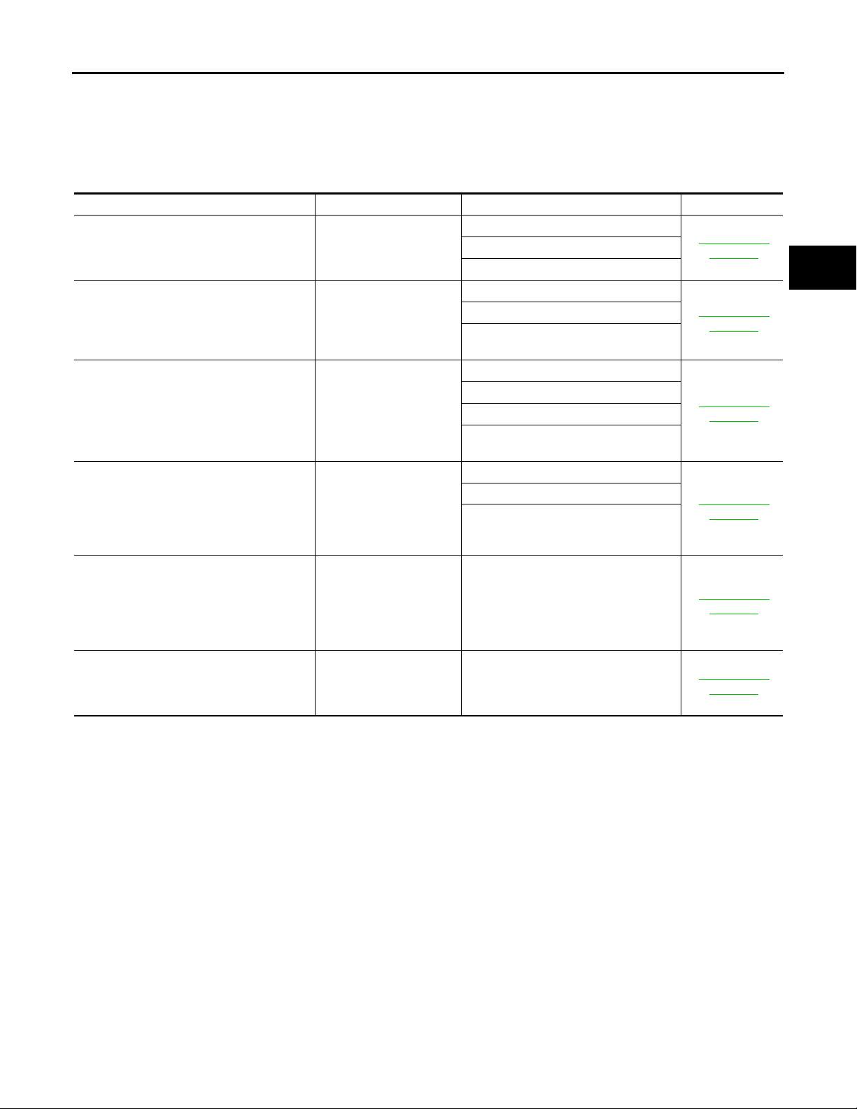
Symptom Table INFOID:0000000000957262
If AWD warning lamp turns ON, perform self-diagnosis.
Symptom Condition Check item Reference
AWD warning lamp does not turn ON when
the ignition switch is turned to ON.
(AWD warning lamp check)
AWD warning lamp does not turn OFF several seconds after engine started.
Heavy tight-corner braking symptom occurs
when the vehicle is driven and the steering
wheel is turned fully to either side after the
engine is started. (See NOTE.)
Vehicle does not enter AWD mode even
though AWD warning lamp turned to OFF.
While driving, AWD warning lamp blinks
quickly. (When blinking in approx. 1 minute
and then turning OFF.)
Quick blinking: 2 times/second
While driving, AWD warning lamp blinks
slowly. (When continuing to blink until turning ignition switch OFF)
Slow blinking: 1 time/2 seconds
NOTE:
Light tight-corner braking symptom may occur depending on driving conditions. This is not malfunction.
Ignition switch: ON
Engine running
• While driving
• Steerin g wheel is
turned fully to either
sides
While driving
While driving
• While driving
• Vehicle speed: 20 km/h
(12 MPH) or more
Unified meter and A/C amp.
CAN communication line
Combination meter
AWD control unit self-diagnosis
AWD warning lamp
Power supply and ground for AWD con-
trol unit
ECM self-diagnosis
AWD control unit self-diagnosis
AWD solenoid
Mechanical malfunction of electric con-
trolled coupling (clutch stic king etc.)
CAN communication line
AWD solenoid
Mechanical malfunction of electric con-
trolled coupling (Mechanical engagement of clutch is not possible.)
Protection function is activated due to
heavy load to electric controlled coupling. (AWD system is not malfunctioning. Also, optional distribution of torque
sometimes becomes rigid before lamp
blinks quickly, but it is not malfunction.)
Tire size is different between front and
rear of vehicle.
DLN-36, "
scription"
DLN-37, "
scription"
DLN-38, "
scription"
DLN-39, "
scription"
DLN-40, "
scription"
DLN-41, "
scription"
De-
De-
De-
De-
De-
De-
A
B
C
DLN
E
F
G
H
I
J
K
L
M
N
O
P
DLN-35
Page 36

AWD WARNING LAMP DOES NOT TURN ON
Revision: October 2006
2007 G35 Sedan
< SYMPTOM DIAGNOSIS >
[TRANSFER: ETX13B]
AWD WARNING LAMP DOES NOT TURN ON
Description INFOID:0000000000957263
• AWD warning lamp does not turn ON when the ignition switch is turned to ON.
Diagnosis Procedure INFOID:0000000000957264
1.CHECK AWD WARNING LAMP
Perform trouble diagnosis for AWD warning lamp. Refer to DLN-25, "
Is the inspection result normal?
YES >> Check each harness connector pin terminal for disconnection.
NO >> Repair or replace damaged parts.
Diagnosis Procedure".
DLN-36
Page 37
AWD WARNING LAMP DOES NOT TURN OFF
Revision: October 2006
2007 G35 Sedan
< SYMPTOM DIAGNOSIS >
[TRANSFER: ETX13B]
AWD WARNING LAMP DOES NOT TURN OFF
Description INFOID:0000000000957265
• AWD warning lamp does not turn OFF several seconds after engine started.
Diagnosis Procedure INFOID:0000000000957266
1.SELF-DIAGNOSIS START
With CONSULT-III
Perform AWD control unit self-diagnosis.
Is any error system detected?
YES >> Check the error system.
NO >> GO TO 2.
2.CHECK AWD WARNING LAMP
Perform AWD warning lamp trouble diagnosis. Refer to DLN-25, "
Is the inspection result normal?
YES >> Repair or replace the specific malfunctioning part.
NO >> GO TO 3.
Description".
3.AWD CONTROL UNIT POWER SUPPLY INSPECTION
Perform AWD control unit power supply trouble diagnosis. Refer to DLN-23, "
Is the inspection result normal?
YES >> Check each harness connector pin terminal for disconnection.
NO >> Repair or replace the specific malfunctioning part.
Description".
A
B
C
DLN
E
F
G
H
I
K
M
N
O
P
J
L
DLN-37
Page 38
HEAVY TIGHT-CORNER BRAKING SYMPTOM OCCURS
Revision: October 2006
2007 G35 Sedan
< SYMPTOM DIAGNOSIS >
[TRANSFER: ETX13B]
HEAVY TIGHT-CORNER BRAKING SYMPTOM OCCURS
Description INFOID:0000000000957267
• Heavy tight-corner braking symptom occurs when the vehicle is driven and the steering wheel is turned fully
to either side after the engine is started.
NOTE:
Light tight-corner braking symptom may occur depending on driving conditions. This is not malfunction.
Diagnosis Procedure INFOID:0000000000957268
1.ECM SELF-DIAGNOSIS
With CONSULT-III
Perform ECM self-diagnosis.
Is any error system detected?
YES >> Check the error system.
NO >> GO TO 2.
2.SELF-DIAGNOSIS STARTS
With CONSULT-III
Perform AWD control unit self-diagnosis.
Is DTC
“U1000” detected?
YES >> Check the error system.
NO >> GO TO 3.
3.AWD SOLENOID INSPECTION
Perform AWD solenoid trouble diagnosis. Refer to DLN-16, "
Is the inspection result normal?
YES >> GO TO 4.
NO >> Repair or replace the specific malfunctioning part.
Description".
4.CHECK ELECTRIC CONTROLLED COUPLING
1. Turn the ignition switch OFF.
2. Set the transmission to neutral. Release the parking brake.
3. Lift up the vehicle.
4. Rotate the rear propeller shaft.
5. Hold the front propeller shaft lightly.
Does the front propeller shaft rotate?
YES >> Replace electric controlled coupling for mechanical malfunction (clutch sticking etc.). Refer to
DLN-69, "
NO >> Check each harness connector pin terminal for disconnection.
Disassembly".
DLN-38
Page 39
VEHICLE DOES NOT ENTER AWD MODE
Revision: October 2006
2007 G35 Sedan
< SYMPTOM DIAGNOSIS >
[TRANSFER: ETX13B]
VEHICLE DOES NOT ENTER AWD MODE
Description INFOID:0000000000957269
• Vehicle does not enter AWD mode even though AWD warning lamp turned to OFF.
Diagnosis Procedure INFOID:0000000000957270
1.CHECK AWD WARNING LAMP
Turn the ignition switch ON.
Does AWD warning lamp turn ON?
YES >> GO TO 2.
NO >> Go to DLN-36, "
Description".
2.SELF-DIAGNOSIS STARTS
With CONSULT-III
Perform AWD control unit self-diagnosis.
Is DTC
“U1000” detected?
YES >> Check the error system.
NO >> GO TO 3.
3.CHECK AWD SOLENOID
Perform AWD solenoid trouble diagnosis. Refer to DLN-16, "
Is the inspection result normal?
YES >> GO TO 4.
NO >> Repair or replace the specific malfunctioning part.
Description".
4.CRUISE TEST
A
B
C
DLN
E
F
G
H
I
Drive the vehicle for a period of time.
Does any symptom occur?
YES >> Replace electric controlled coupling for mechanical malfunction (mechanical engagement of
clutch is not possible). Refer to DLN-69, "
NO >> Check each harness connector pin terminal for disconnection.
Disassembly".
J
K
L
M
N
O
P
DLN-39
Page 40

AWD WARNING LAMP BLINKS QUICKLY
Revision: October 2006
2007 G35 Sedan
< SYMPTOM DIAGNOSIS >
[TRANSFER: ETX13B]
AWD WARNING LAMP BLINKS QUICKLY
Description INFOID:0000000000957271
• While Driving, AWD warning lamp blinks 2 times in 1 second and it turns OFF after 1 minute while driving.
- This symptom protects drivetrain parts when a heavy load is applied to the electric controlled coupling and
multiple disc clutch temperature increases. Also, optional distribution of torque sometimes becomes rigid
before lamp blinks quickly. Both cases are not malfunction.
- When this symptom occurs, stop vehicle and allow it to idle for some times. Blinking will stop and system will
be restored.
DLN-40
Page 41
AWD WARNING LAMP BLINKS SLOWLY
Revision: October 2006
2007 G35 Sedan
< SYMPTOM DIAGNOSIS >
[TRANSFER: ETX13B]
AWD WARNING LAMP BLINKS SLOWLY
Description INFOID:0000000000957272
• AWD warning lamp blinks at approximately 2 seconds intervals while driving.
Diagnosis Procedure INFOID:0000000000957273
1.CHECK TIRE
• Check the following.
- Tire pressure
- Wear condition
- Longitudinal tire size (There is no difference between longitudinal tires.)
Is the inspection result normal?
YES >> GO TO 2.
NO >> Drive at vehicle speed of 20 km/h (12 MPH) or more for 5 seconds or more after repairing or
replacing damaged parts. (Initialize improper size tire information.)
2.CHECK INPUT SIGNAL OF TIRE DIAMETER
With CONSULT-III
1. Start engine.
2. Drive at 20 km/h (12 MPH) or more for approx. 200 seconds.
3. Check “DIS-TIRE MONI” of AWD control unit CONSULT-III “DATA MONITOR”.
Does the item on
YES >> INSPECTION END
NO >> GO TO 3.
“DATA MONITOR” indicate “0 - 4 mm”?
3.TERMINAL INSPECTION
Check AWD control unit harness connector for disconnection.
Is the inspection result normal?
YES >> Replace AWD control unit. Refer to DLN-49, "Exploded View".
NO >> Repair or replace the specific malfunctioning part.
A
B
C
DLN
E
F
G
H
I
J
K
M
N
O
P
L
DLN-41
Page 42

NORMAL OPERATING CONDITION
Revision: October 2006
2007 G35 Sedan
< SYMPTOM DIAGNOSIS >
[TRANSFER: ETX13B]
NORMAL OPERATING CONDITION
Description INFOID:0000000000957274
• While Driving, AWD warning lamp blinks 2 times in 1 second and it turns OFF after 1 minute while driving.
- This symptom protects drivetrain parts when a heavy load is applied to the electric controlled coupling and
multiple disc clutch temperature increases. Also, optional distribution of torque sometimes becomes rigid
before lamp blinks quickly. Both cases are not malfunction.
- When this symptom occurs, stop vehicle and allow it to idle for some times. Blinking will stop and system will
be restored.
DLN-42
Page 43
NOISE, VIBRATION AND HARSHNESS (NVH) TROUBLESHOOTING
Revision: October 2006
2007 G35 Sedan
< SYMPTOM DIAGNOSIS >
[TRANSFER: ETX13B]
NOISE, VIBRATION AND HARSHNESS (NVH) TROUBLESHOOTING
NVH Troubleshooting Chart INFOID:0000000000957275
Use the chart below to help you find the cause of the symptom. The numbers indicate the order of the inspection. If necessary, repair or replace these parts.
Reference
DLN-48, "Inspection"
SUSPECTED PARTS
(Possible cause)
DLN-58, "Exploded View"
DLN-58, "Exploded View"
DLN-67, "Inspection"
DLN-67, "Inspection"
DLN-67, "Inspection"
A
B
C
DLN
E
F
G
H
Symptom
TRANSFER FLUID (Level low)
Noise 1 2 3 3 3
Transfer fluid leakage 4 1 2 2 3
TRANSFER FLUID (Wrong)
TRANSFER FLUID (Level too high)
LIQUID GASKET (Damaged)
OIL SEAL (Worn or damaged)
GEAR (Worn or damaged)
BEARING (Worn or damaged)
TRANSFER CASE (Damaged)
I
J
K
L
M
N
O
P
DLN-43
Page 44

PRECAUTIONS
Revision: October 2006
2007 G35 Sedan
< PRECAUTION >
[TRANSFER: ETX13B]
PRECAUTION
PRECAUTIONS
Precaution for Supplemental Restraint System (SRS) "AIR BAG" and "SEAT BELT PRE-TENSIONER" INFOID:0000000000957276
The Supplemental Restraint System such as “AIR BAG” and “SEAT BELT PRE-TENSIONER”, used along
with a front seat belt, helps to reduce the risk or severity of injury to the driver and front passenger for certain
types of collision. This system includes seat belt switch inputs and dual stage front air bag modules. The SRS
system uses the seat belt switches to determine the front air bag deployment, and may only deploy one front
air bag, depending on the severity of a collision and whether the front occupants are belted or unbelted.
Information necessary to service the system safely is included in the SRS and SB section of this Service Manual.
WARNING:
• To avoid rendering the SRS inoperative, which could increase the risk of personal injury or death in
the event of a collision which would result in air bag inflation, all maintenance must be performed by
an authorized NISSAN/INFINITI dealer.
• Improper maintenance, including incorrect removal and installation of the SRS, can lead to personal
injury caused by unintentional activation of the system. For removal of Spiral Cable and Air Bag
Module, see the SRS section.
• Do not use electrical test equipment on any circuit related to the SRS unless instructed to in this
Service Manual. SRS wiring harnesses can be identified by yellow and/or orange harnesses or harness connectors.
Service Notice or Precautions for Transfer INFOID:0000000000957277
CAUTION:
• Never reuse transfer fluid, once it has been drained.
• Check the fluid level or replace the fluid only with the vehicle parked on level ground.
• During removal or installation, keep inside of transfer clear of dust or dirt.
• Replace all tires at the same time. Always use tires of the proper size and the same brand and pattern. Fitting improper size and unusual wear tires applies excessive force to vehicle mechanism and
can cause longitudinal vibration.
• Disassembly should be done in a clean work area, it is preferable to work in dustproof area.
• Before proceeding with disassembly, thoroughly clean the transfer. It is important to prevent the
internal parts from becoming contaminated by dirt or other foreign matter.
• All parts should be carefully cleaned with a general purpose, non-flammable solvent before inspection or reassembly.
• Check for the correct installation status prior to removal or disassembly. If matching marks are
required, be certain they do not interfere with the function of the parts when applied.
• Check appearance of the disassembled parts for damage, deformation, and unusual wear. Replace
them with a new ones if necessary.
• Gaskets, seals and O-rings should be replaced any time when the transfer is disassembled.
• In principle, tighten bolts or nuts gradually in several steps working diagonally from inside to outside. If tightening sequence is specified, use it.
• Observe the specified torque when assembling.
• Clean and flush the parts sufficient ly and blow-dry them.
• Be careful not to damage sliding surfaces and mating surfaces.
• Clean inner parts with lint-free cloth or towels. Do not use cotton work gloves and rags to prevent
adhering fibers.
DLN-44
Page 45
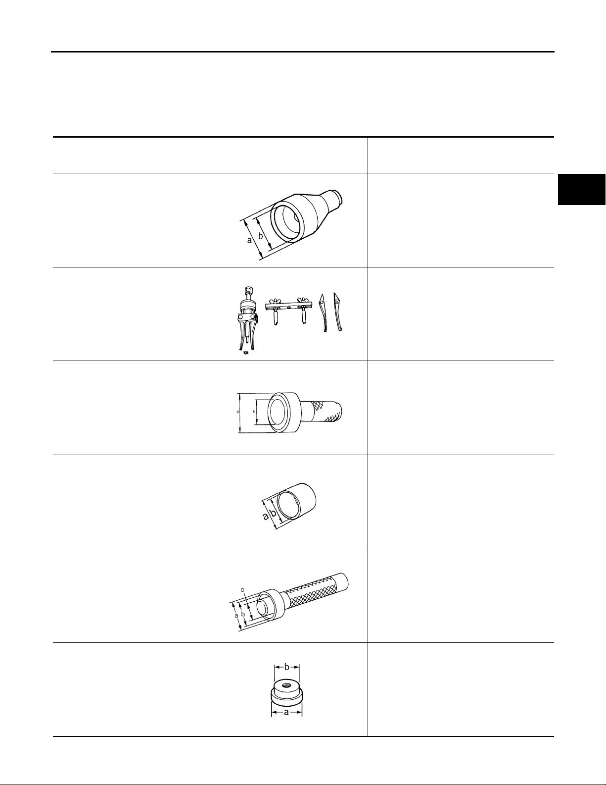
< PREPARATION >
Revision: October 2006
2007 G35 Sedan
PREPARATION
[TRANSFER: ETX13B]
PREPARATION
PREPARATION
Special Service Tools INFOID:0000000000957278
The actual shapes of Kent-Moore tools may differ from those of special service tools illustrated here.
Tool number
(Kent-Moore No.)
Tool name
ST27862000
(—)
Drift
a: 62.5 mm (2.461 in) dia.
b: 42 mm (1.65 in) dia.
ZZA0194D
KV381054S0
(J-34286)
Puller
ZZA0601D
ST30720000
(J-25405)
Drift
a: 77 mm (3.03 in) dia.
b: 55.5 mm (2.185 in) dia.
Description
Installing front oil seal
Removing rear oil seal
• Installing rear oil seal
• Installing mainshaft oil seal
A
B
C
DLN
E
F
G
H
I
KV40104830
(—)
Drift
a: 70 mm (2.76 in) dia.
b: 63.5 mm (2.500 in) dia.
KV38100300
(J-25523)
Drift
a: 54 mm (2.13 in) dia.
b: 46 mm (1.81 in) dia.
c: 32 mm (1.26 in) dia.
ST33052000
(—)
Drift
a: 28 mm (1.10 in) dia.
b: 22 mm (0.87 in) dia.
ZZA0811D
ZZA1003D
ZZA1046D
Installing rear oil seal
Removing mainshaft bearing
Removing mainshaft assembly
J
K
L
M
N
O
P
ZZA1000D
DLN-45
Page 46
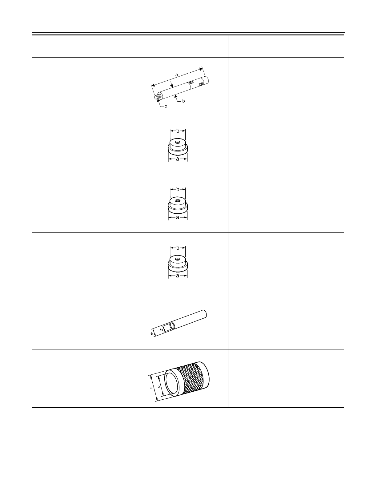
< PREPARATION >
Revision: October 2006
2007 G35 Sedan
Tool number
(Kent-Moore No.)
Tool name
ST30611000
(J-25742-1)
Drift bar
a: 350 mm (13.78 in)
b: 25 mm (0.98 in) dia.
c: M12 × 1.5P
ST35321000
(—)
Drift
a: 49 mm (1.93 in) dia.
b: 41 mm (1.61 in) dia.
KV38104010
(—)
Drift
a: 67 mm (2.64 in) dia.
b: 49 mm (1.93 in) dia.
PREPARATION
[TRANSFER: ETX13B]
Description
Removing rear bearing
NT663
• Removing rear bearing
• Installing mainshaft assembly
ZZA1000D
• Installing front drive shaft rear bearing
• Installing rear bearing
ST30621000
(J-25742-5)
Drift
a: 80 mm (3.15 in) dia.
b: 59 mm (2.32 in) dia.
ST31214000
(J-25269-B)
Drift
a: 34 mm (1.34 in) dia.
b: 25.5 mm (1.004 in) dia.
ST33200000
(J-26082)
Drift
a: 60 mm (2.36 in) dia.
b: 44.5 mm (1.752 in) dia.
ZZA1000D
Installing mainshaft bearing
ZZA1000D
• Removing front drive shaft front bearing
• Removing front drive shaft rear bearing
ZZA0534D
Installing front drive shaft front bearing
ZZA1002D
Commercial Service Tools
INFOID:0000000000957279
DLN-46
Page 47
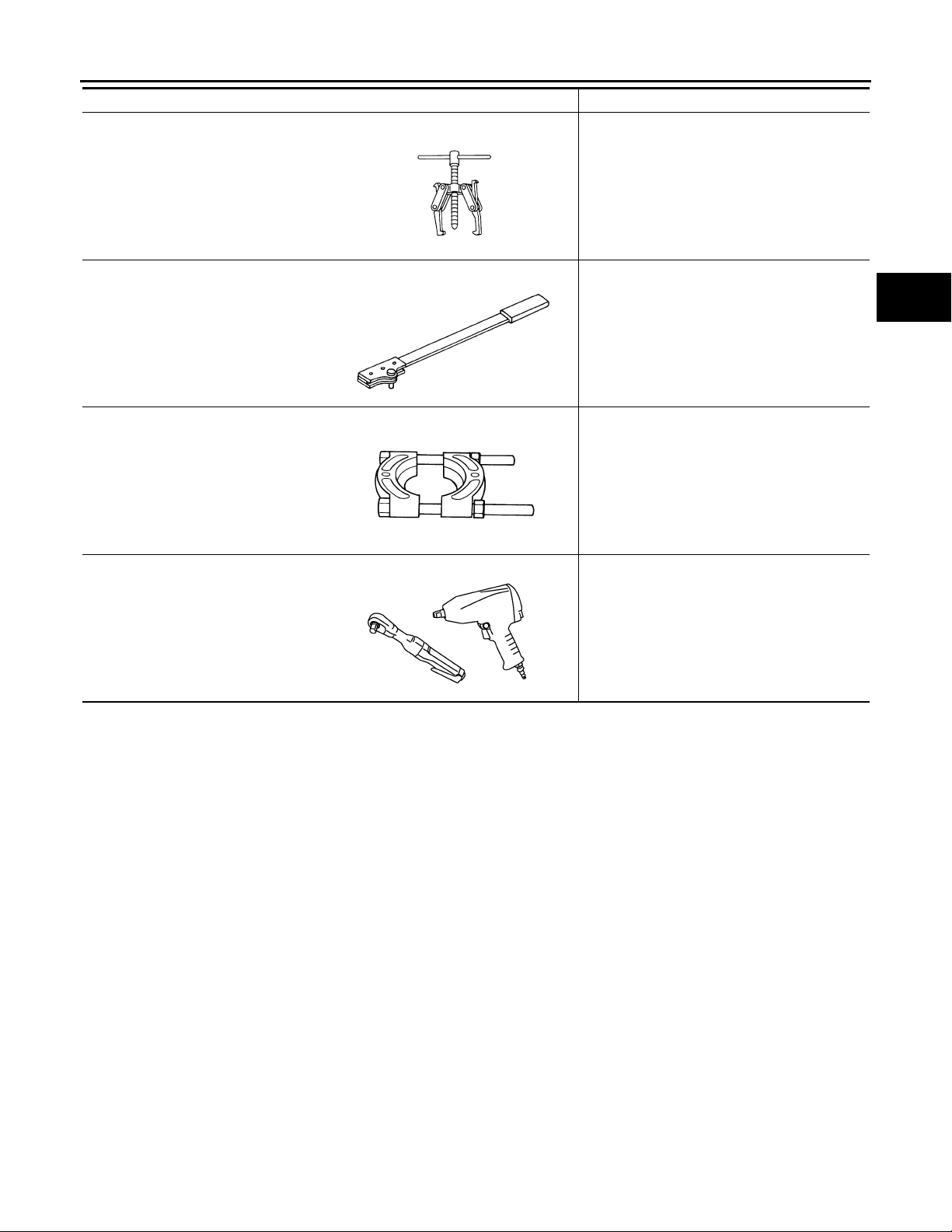
< PREPARATION >
Revision: October 2006
2007 G35 Sedan
PREPARATION
[TRANSFER: ETX13B]
Tool name Description
Puller Removing companion flange
NT077
Flange wrench Removing and installing self-lock nut
NT771
Puller • Removing front drive shaft front bearing
• Removing front drive shaft rear bearing
ZZB0823D
Power tool Loosening bolts and nuts
A
B
C
DLN
E
F
G
H
PBIC0190E
I
J
K
L
M
N
O
P
DLN-47
Page 48
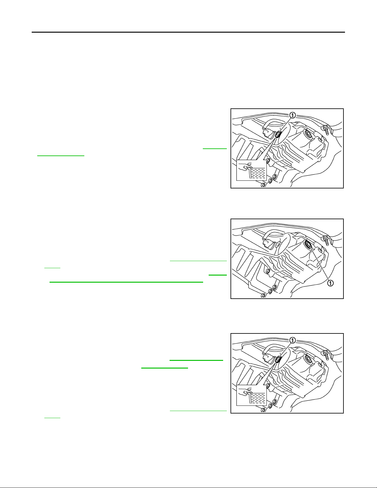
TRANSFER FLUID
Revision: October 2006
2007 G35 Sedan
< ON-VEHICLE MAINTENANCE >
[TRANSFER: ETX13B]
ON-VEHICLE MAINTENANCE
TRANSFER FLUID
Inspection INFOID:0000000000957280
FLUID LEAKAGE
• Check if fluid is leaking from transfer or around it.
FLUID LEVEL
• Check fluid level from filler plug (1) mounting hole as shown in the
figure.
CAUTION:
Never start engine while checking fluid level.
• Before installing filler plug, set a new gasket. Install filler plug on
transfer and tighten to the specified torque. Refer to DLN-58,
"Exploded View".
CAUTION:
Never reuse gasket.
JSDIA0096ZZ
Draining INFOID:0000000000957281
1. Run the vehicle to warm up the transfer unit sufficiently.
2. Stop the engine, and remove the drain plug (1) to drain the
transfer fluid.
CAUTION:
When draining fluid, protect exhaust tube flange with cover.
3. Apply sealant to drain plug. Install drain plug on transfer and
tighten to the specified torque. Refer to DLN-58, "
View".
• Use Genuine Silicone RTV or equivalent. Refer to GI-15,
"Recommended Chemical Products and Sealants".
CAUTION:
Remove old sealant adhering to mounting surfaces. Also
remove any moisture, oil, or foreign material adhering to
application and mounting surfaces.
Exploded
JSDIA0095ZZ
Refilling INFOID:0000000000957282
1. Remove filler plug (1) and add transfer fluid until fluid level
reaches the specified limit near filler plug mounting hole.
Fluid capacity : Refer to DLN-76, "General
Specifications".
CAUTION:
Carefully fill the fluid. (Fill up for approx. 3 minutes.)
2. Leave the vehicle for 3 minutes, and check the fluid level again.
3. Set a new gasket onto filler plug and install it on transfer and
tighten to the specified torque. Refer to DLN-58, "
View".
CAUTION:
Never reuse gasket.
Exploded
JSDIA0096ZZ
DLN-48
Page 49
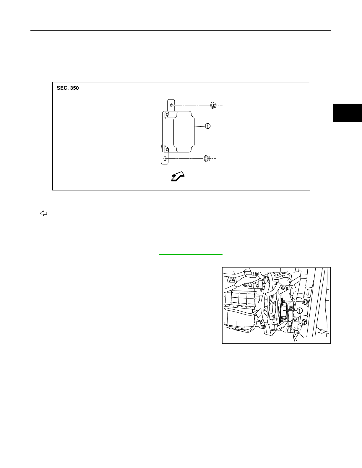
< ON-VEHICLE REPAIR >
Revision: October 2006
2007 G35 Sedan
AWD CONTROL UNIT
[TRANSFER: ETX13B]
ON-VEHICLE REPAIR
AWD CONTROL UNIT
Exploded View INFOID:0000000000957283
JSDIA0050ZZ
1. AWD control unit
: Vehicle front
A
B
C
DLN
E
F
G
H
Removal and Installation INFOID:0000000000957284
REMOVAL
1. Remove the glove box assembly. Refer to IP-11, "Exploded View".
2. Disconnect AWD control unit harness connector.
3. Remove AWD control unit (1) mounting nuts.
4. Remove AWD control unit.
JSDIA0051ZZ
INSTALLATION
Install is the reverse order of removal.
I
J
K
L
M
N
O
P
DLN-49
Page 50
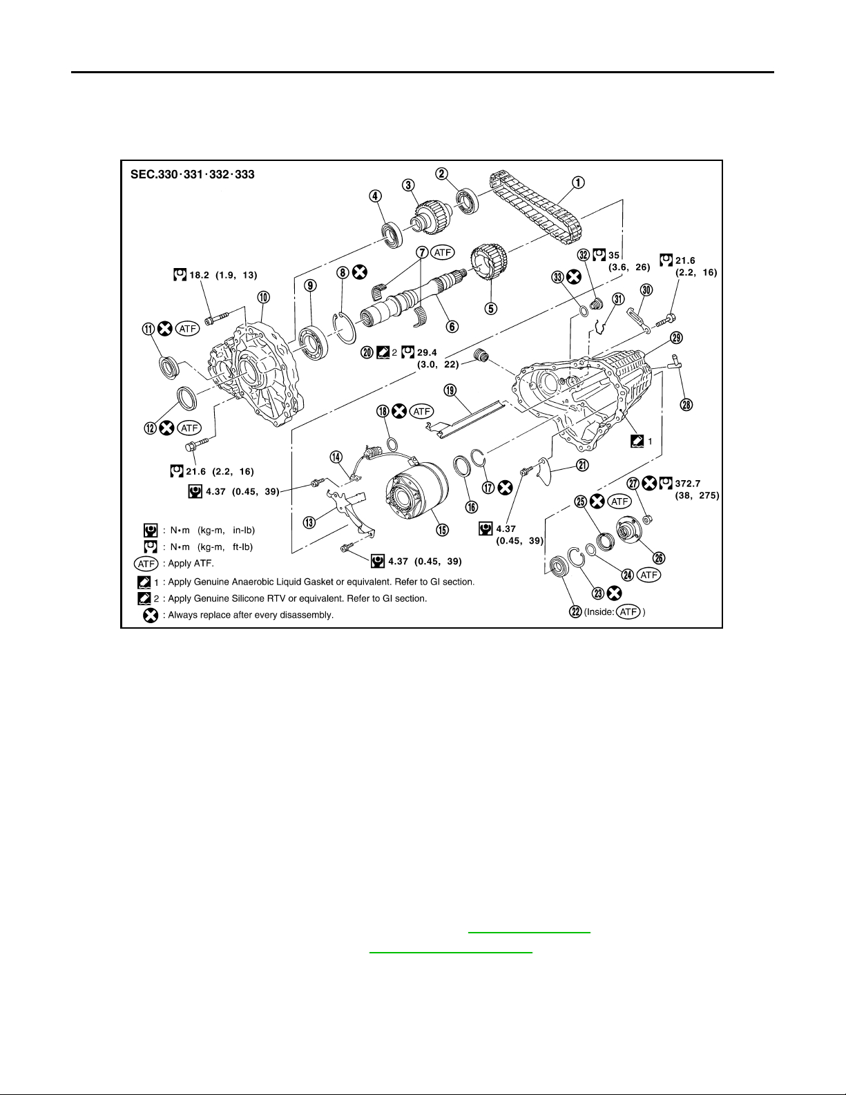
FRONT OIL SEAL
Revision: October 2006
2007 G35 Sedan
< ON-VEHICLE REPAIR >
[TRANSFER: ETX13B]
FRONT OIL SEAL
Exploded View INFOID:0000000000957285
PDIA0244E
1. Drive chain 2. Fro nt driv e sh aft rear bear ing 3. Front driv e sh aft
4. Front drive shaft front bearing 5. Sprocket 6. Mainshaft
7. Needle bearing 8. Snap ring 9. Mainshaft bearing
10. Front case 11. Front oil seal 12. Mainshaft oil seal
13. Oil cover 14. Temperature sensor 15. Electric controlled coupling
16. Spacer 17. Snap ring 18. O-ring
19. Oil gutter 20. Drain plug 21. Baffle plate
22. Rear bearing 23. Snap ring 24. Spacer
25. Rear oil seal 26. Companion flange 27. Self-lock nut
28. Breather tube 29. Rear case 30. Harness bracket
31. Retainer 32. Filler plug 33. Gasket
Removal and Installation INFOID:0000000000957286
REMOVAL
1. Remove the drain plug to drain the transfer fluid. Refer to DLN-48, "Draining".
2. Remove the front propeller shaft. Refer to DLN-80, "
Exploded View".
DLN-50
Page 51
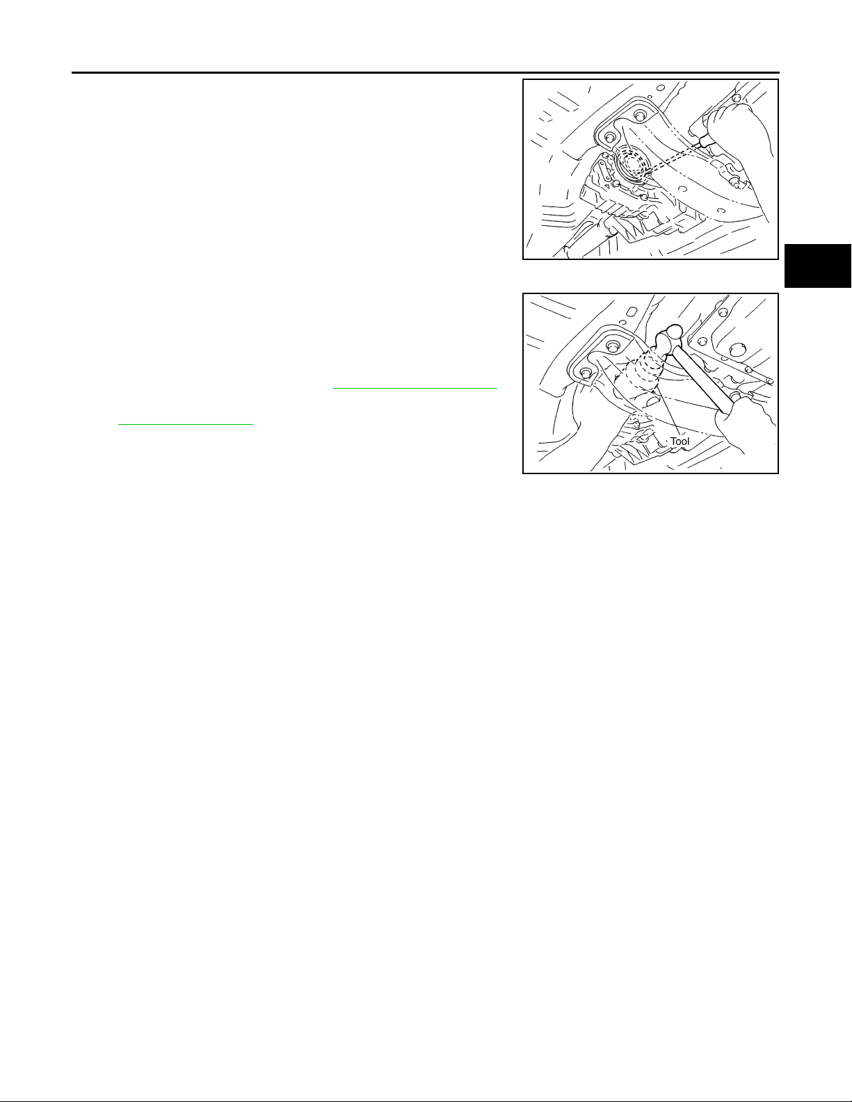
FRONT OIL SEAL
Revision: October 2006
2007 G35 Sedan
< ON-VEHICLE REPAIR >
3. Remove front oil seal using a flat-bladed screwdriver.
CAUTION:
Never damage the front case and front drive shaft.
INSTALLATION
1. Apply ATF to front oil seal, install it with a drift [SST:
ST27862000 ( — )] until the end face of front case.
CAUTION:
• Never reuse front oil seal.
• When installing, never incline front oil seal.
2. Install front propeller shaft. Refer to DLN-80, "
3. Install transfer fluid, check fluid level and for fluid leakage. Refer
to DLN-48, "
Inspection".
Exploded View".
[TRANSFER: ETX13B]
A
B
C
PDIA0537J
DLN
E
F
G
SDIA1783E
H
I
J
K
L
M
N
O
P
DLN-51
Page 52
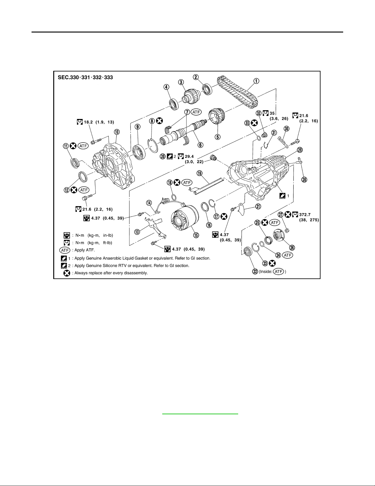
REAR OIL SEAL
Revision: October 2006
2007 G35 Sedan
< ON-VEHICLE REPAIR >
[TRANSFER: ETX13B]
REAR OIL SEAL
Exploded View INFOID:0000000000957287
PDIA0244E
1. Drive chain 2. Fro nt driv e sh aft rear bear ing 3. Front driv e sh aft
4. Front drive shaft front bearing 5. Sprocket 6. Mainshaft
7. Needle bearing 8. Snap ring 9. Mainshaft bearing
10. Front case 11. Front oil seal 12. Mainshaft oil seal
13. Oil cover 14. Temperature sensor 15. Electric controlled coupling
16. Spacer 17. Snap ring 18. O-ring
19. Oil gutter 20. Drain plug 21. Baffle plate
22. Rear bearing 23. Snap ring 24. Spacer
25. Rear oil seal 26. Companion flange 27. Self-lock nut
28. Breather tube 29. Rear case 30. Harness bracket
31. Retainer 32. Filler plug 33. Gasket
Removal and Installation INFOID:0000000000957288
REMOVAL
1. Remove the rear propeller shaft. Refer to DLN-101, "Exploded View".
DLN-52
Page 53
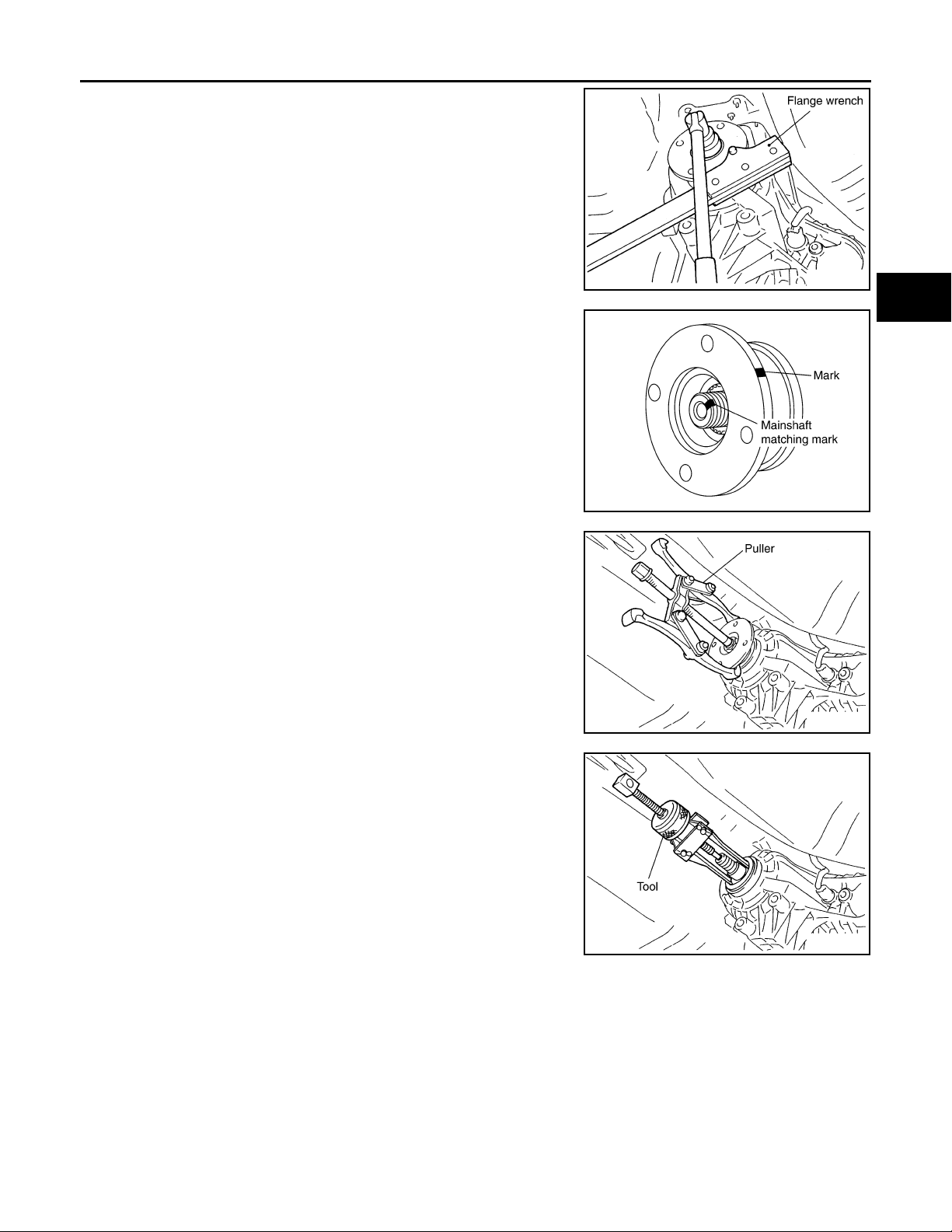
REAR OIL SEAL
Revision: October 2006
2007 G35 Sedan
< ON-VEHICLE REPAIR >
2. Remove self-lock nut of companion flange using flange wrench.
3. Put matching mark on the end of the mainshaft. The mark
should be in line with the mark on the companion flange.
CAUTION:
For matching mark, use paint. Never damage mainshaft.
[TRANSFER: ETX13B]
A
B
C
SDIA2454E
DLN
E
F
G
SDIA2378E
4. Remove the companion flange using a puller.
CAUTION:
Never damage the companion flange.
5. Remove the rear oil seal using the puller [SST: KV381054S0 (J-
34286)].
CAUTION:
Never damage the rear case.
INSTALLATION
SDIA1785E
SDIA1786E
H
I
J
K
L
M
N
O
P
DLN-53
Page 54
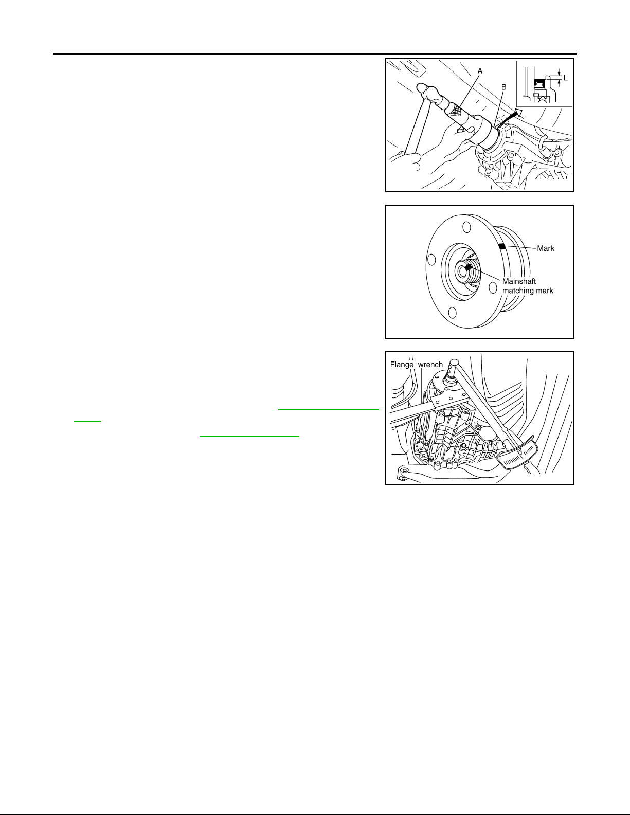
REAR OIL SEAL
Revision: October 2006
2007 G35 Sedan
< ON-VEHICLE REPAIR >
1. Apply ATF to rear oil seal, install it with drifts.
A: Drift [ST30720000 (J-25405)]
B: Drift [KV40104830 ( — )]
Dimension “L” : 6.7 – 7.3 mm (0.264 – 0.287 in)
CAUTION:
• Never reuse rear oil seal.
• When installing, never incline rear oil seal.
2. Align the matching mark of mainshaft with the mark of companion flange, then install the companion flange.
[TRANSFER: ETX13B]
JSDIA0167ZZ
3. Using a flange wrench, install the self-lock nut of companion
flange and tighten to the specified torque.
CAUTION:
Never reuse self-lock nut.
4. Install the rear propeller shaft. Refer to DLN-101, "
Exploded
View".
5. Check fluid level. Refer to DLN-48, "
Inspection".
SDIA2378E
PDIA0245E
DLN-54
Page 55
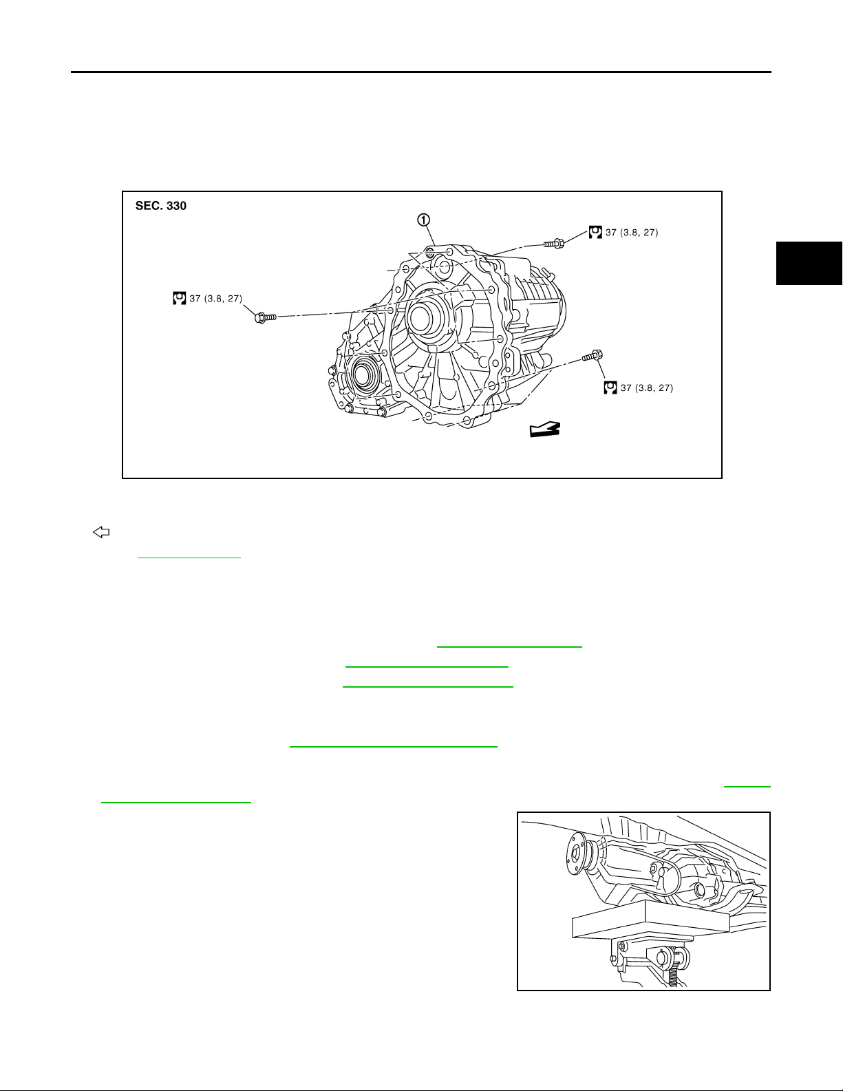
< REMOVAL AND INSTALLATION >
Revision: October 2006
2007 G35 Sedan
TRANSFER ASSEMBLY
[TRANSFER: ETX13B]
REMOVAL AND INSTALLATION
TRANSFER ASSEMBLY
Exploded View INFOID:0000000000957289
JSDIA0052GB
1. Transfer assembly
A
B
C
DLN
E
F
G
H
: Vehicle front
Refer to GI-4, "
Components" for symbols in the figure.
Removal and Installation INFOID:0000000000957290
REMOVAL
1. Remove exhaust front tube with power tool. Refer to EX-5, "Exploded View".
2. Remove front propeller shaft. Refer to DLN-80, "
3. Remove rear propeller shaft. Refer to DLN-101, "
4. Disconnect AWD solenoid harness connector and separate harness from transfer assembly.
5. Remove transfer air breather hose.
6. Remove control rod. Refer to TM-236, "
7. Support transfer assembly and transmission assembly with a jack.
8. Remove rear engine mounting member and engine mounting insulator with power tool. Refer to EM-81,
"AWD : Exploded View".
9. Lower jack to the position where the top transfer mounting bolts
can be removed.
10. Remove transfer mounting bolts with power tool and separate
transfer from transmission.
CAUTION:
Secure transfer assembly and transmission assembly to a
jack.
AWD : Exploded View".
Exploded View".
Exploded View".
I
J
K
L
M
N
O
P
INSTALLATION
Note the following, and install in the reverse order of removal.
PDIA0560J
DLN-55
Page 56
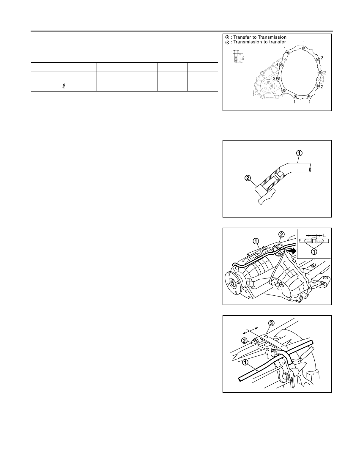
TRANSFER ASSEMBLY
Revision: October 2006
2007 G35 Sedan
< REMOVAL AND INSTALLATION >
• When installing the transfer to the transmission, install the mounting bolts following the standard below, tighten bolts to the specified
torque.
Bolt No. 1234
Quantity 4321
Bolt length “ ” mm (in)
75 (2.95) 45 (1.77) 40 (1.57) 30 (1.18)
• When installing transfer air breather hose, make sure there are no pinched or restricted areas on the transfer
air breather hose caused by bending or winding.
- Set transfer air breather hose with paint mark facing upward.
- Be sure to insert transfer air breather hose (1) into breather tube
(2) until hose end reaches the tube's base.
[TRANSFER: ETX13B]
SDIA2284E
- Do not deviate from the range (L) of the transfer air breather when
installing the transfer air breather hose (1) to the harness bracket
(2) of the transfer.
- Install transfer air breather hose (1) with bracket between the
adapter case (2) and the transmission case (3).
JSDIA0053ZZ
JSDIA0054ZZ
JSDIA0055ZZ
DLN-56
Page 57
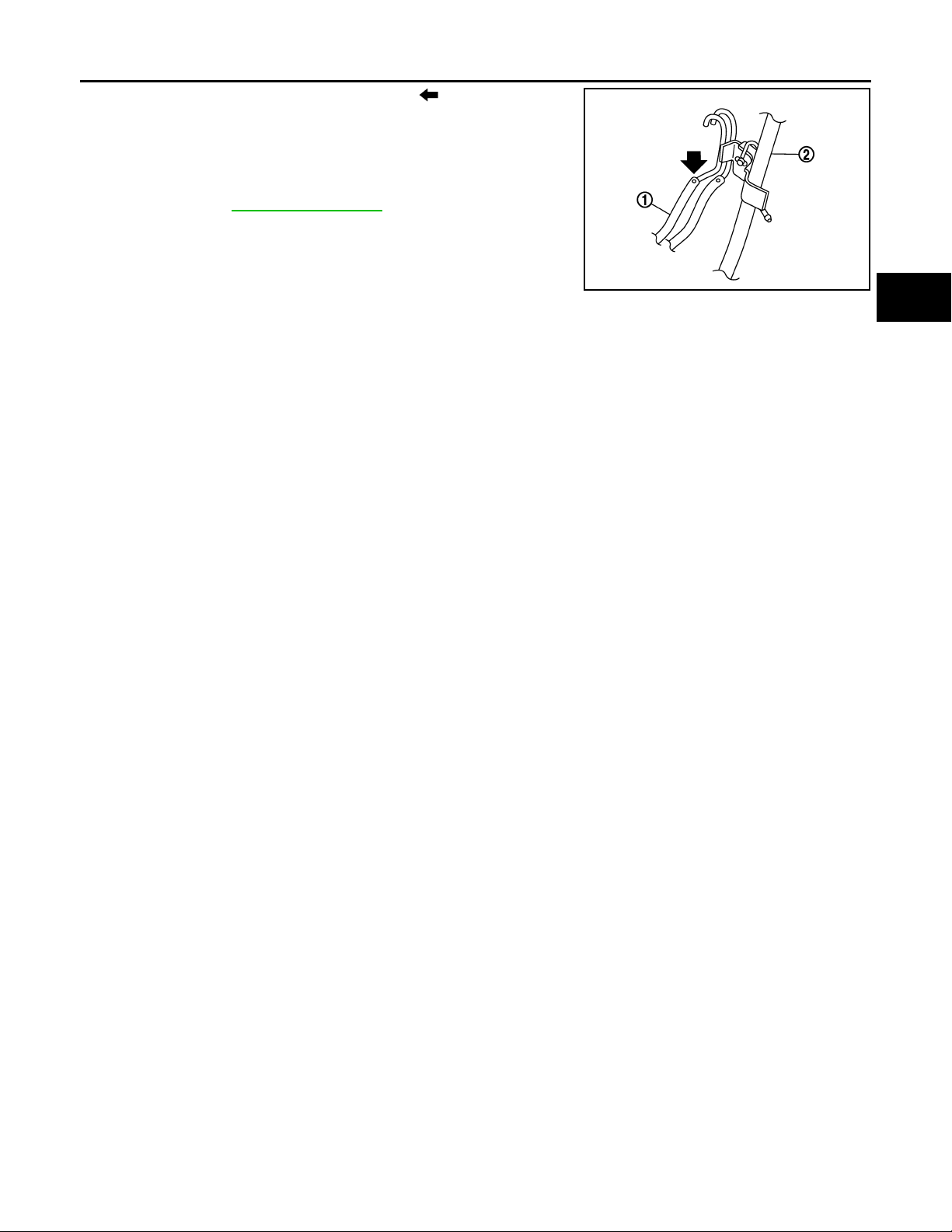
TRANSFER ASSEMBLY
Revision: October 2006
2007 G35 Sedan
< REMOVAL AND INSTALLATION >
- Check that transfer breather hose is on the ( ) side when installing the transfer air breather hose (1) to A/T fluid charging pipe (2).
- Be sure to insert air breather hose to transfer tube until hose end
reaches the tube's base and another hose end reaches the tube
bend R portion of A/T fluid charging pipe.
• After the installation, check the fluid level, fluid leakage and the A/T
positions. Refer to DLN-48, "
Inspection".
[TRANSFER: ETX13B]
A
B
C
JSDIA0056ZZ
DLN
E
F
G
H
K
M
N
O
I
J
L
P
DLN-57
Page 58
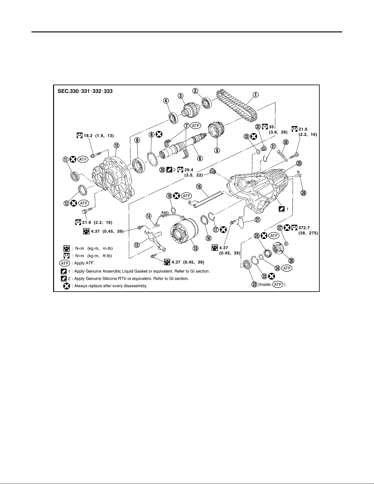
FRONT CASE AND REAR CASE
Revision: October 2006
2007 G35 Sedan
< DISASSEMBLY AND ASSEMBLY >
[TRANSFER: ETX13B]
DISASSEMBLY AND ASSEMBLY
FRONT CASE AND REAR CASE
Exploded View INFOID:0000000000957291
PDIA0244E
1. Drive chain 2. Fro nt driv e sh aft rear bear ing 3. Front driv e sh aft
4. Front drive shaft front bearing 5. Sprocket 6. Mainshaft
7. Needle bearing 8. Snap ring 9. Mainshaft bearing
10. Front case 11. Front oil seal 12. Mainshaft oil seal
13. Oil cover 14. Temperature sensor 15. Electric controlled coupling
16. Spacer 17. Snap ring 18. O-ring
19. Oil gutter 20. Drain plug 21. Baffle plate
22. Rear bearing 23. Snap ring 24. Spacer
25. Rear oil seal 26. Companion flange 27. Self-lock nut
28. Breather tube 29. Rear case 30. Harness bracket
31. Retainer 32. Filler plug 33. Gasket
Disassembly INFOID:0000000000957292
1. Remove drain plug and filler plug.
DLN-58
Page 59
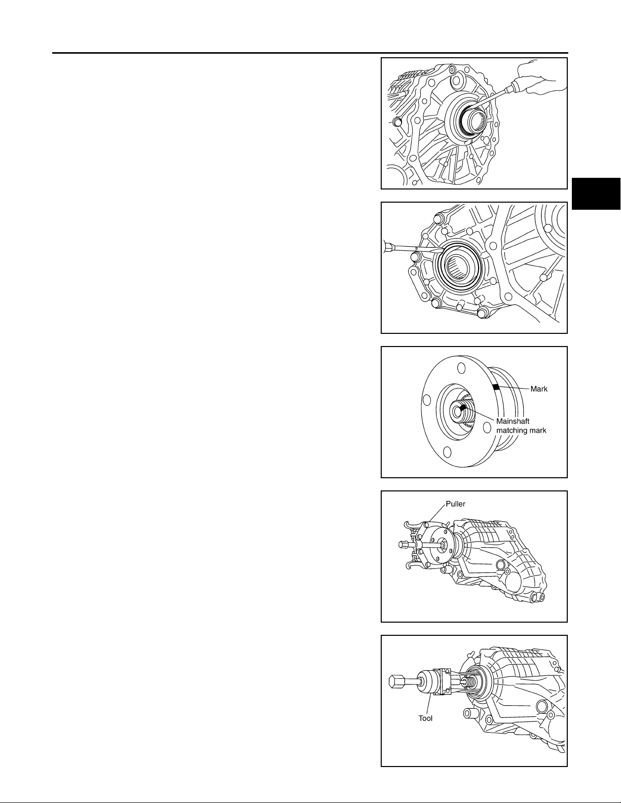
FRONT CASE AND REAR CASE
Revision: October 2006
2007 G35 Sedan
< DISASSEMBLY AND ASSEMBLY >
2. Remove mainshaft oil seal from front case, using a flat-bladed
screwdriver.
CAUTION:
Never damage the front case and mainshaft.
3. Remove front oil seal from front case, using a flat-bladed screw-
driver.
CAUTION:
Never damage the front case and front drive shaft.
4. Remove self-lock nut.
[TRANSFER: ETX13B]
A
B
C
PDIA0507J
DLN
E
F
G
PDIA0255E
5. Put a matching mark on the end of mainshaft. The mark should
be in line with the mark on the companion flange.
CAUTION:
For matching mark, use paint. Never damage mainshaft.
6. Remove companion flange, using a puller.
CAUTION:
Never damage the companion flange.
7. Remove rear oil seal from rear case, using the puller [SST:
KV381054S0 (J-34286)].
CAUTION:
Never damage the rear case.
SDIA2378E
PDIA0258E
H
I
J
K
L
M
N
O
P
PDIA0259E
DLN-59
Page 60
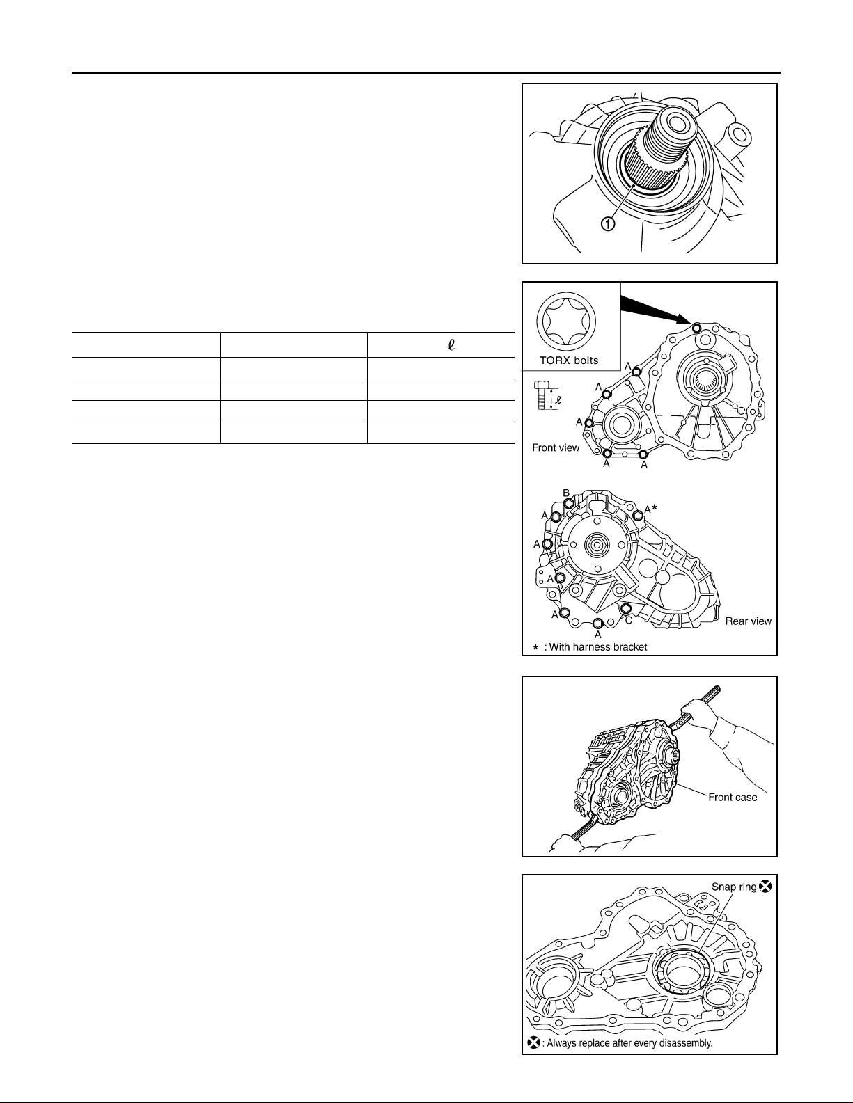
FRONT CASE AND REAR CASE
Revision: October 2006
2007 G35 Sedan
< DISASSEMBLY AND ASSEMBLY >
8. Remove spacer (1) from mainshaft.
9. Remove front case and rear case fixing bolts, then remove harness bracket.
[TRANSFER: ETX13B]
JSDIA0097ZZ
Bolts symbol Quantity
A 11 42 (1.65)
B 1 162 (6.38)
C197 (3.82)
TORX bolts 1 40 (1.57)
Bolt length “ ” mm (in)
10. Separate front case and rear case. Then, remove front case by
levering it up with a tire lever or the like.
CAUTION:
Never damage the mating surface.
PDIA0251E
11. Remove snap ring from front case.
SDIA2460E
PDIA0267E
DLN-60
Page 61
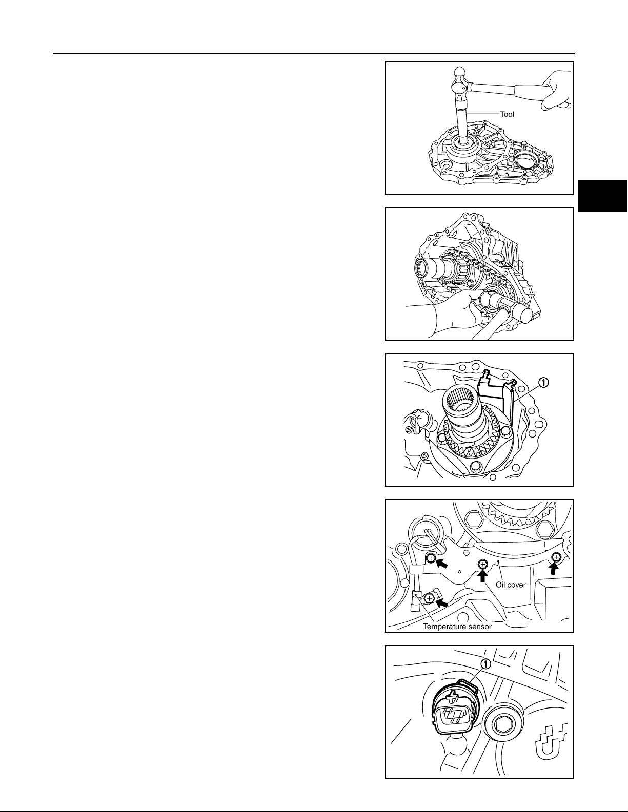
FRONT CASE AND REAR CASE
Revision: October 2006
2007 G35 Sedan
< DISASSEMBLY AND ASSEMBLY >
[TRANSFER: ETX13B]
12. Remove mainshaft bearing from front case, using the drift [SST:
KV38100300 (J-25523)].
13. Remove drive chain and front drive shaft while tapping front
drive shaft with plastic hammer.
CAUTION:
Never tap drive chain.
14. Remove oil gutter (1) from rear case.
PDIA0256E
PDIA0257E
A
B
C
DLN
E
F
G
H
15. Remove oil cover bolt and sensor fixing bolt from rear case. And
then, remove oil cover.
16. Remove retainer (1) from AWD solenoid harness connector.
17. Remove AWD solenoid harness connector from rear case.
18. Remove O-ring from AWD solenoid harness connector.
JSDIA0098ZZ
SDIA2403E
I
J
K
L
M
N
O
P
JSDIA0100ZZ
DLN-61
Page 62
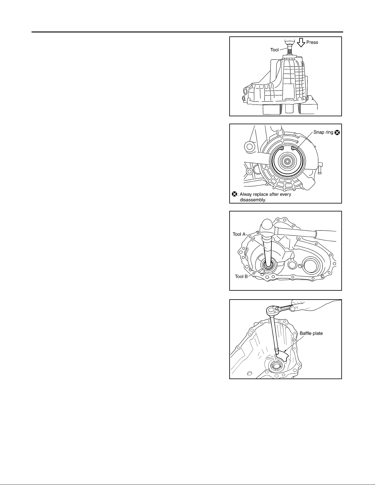
FRONT CASE AND REAR CASE
Revision: October 2006
2007 G35 Sedan
< DISASSEMBLY AND ASSEMBLY >
19. Remove mainshaft assembly from rear case, using the drift
[SST: ST33052000 ( — )].
20. Remove snap ring from rear case.
[TRANSFER: ETX13B]
PDIA0262E
21. Remove rear bearing from rear case, using the drifts.
A: Drift bar [ST30611000 (J-25742-1)]
B: Drift [ST35321000 ( — )]
22. Remove baffle plate from rear case.
23. Remove breather tube from rear case.
PDIA0263E
PDIA0264E
SDIA1701E
Assembly INFOID:0000000000957293
DLN-62
Page 63
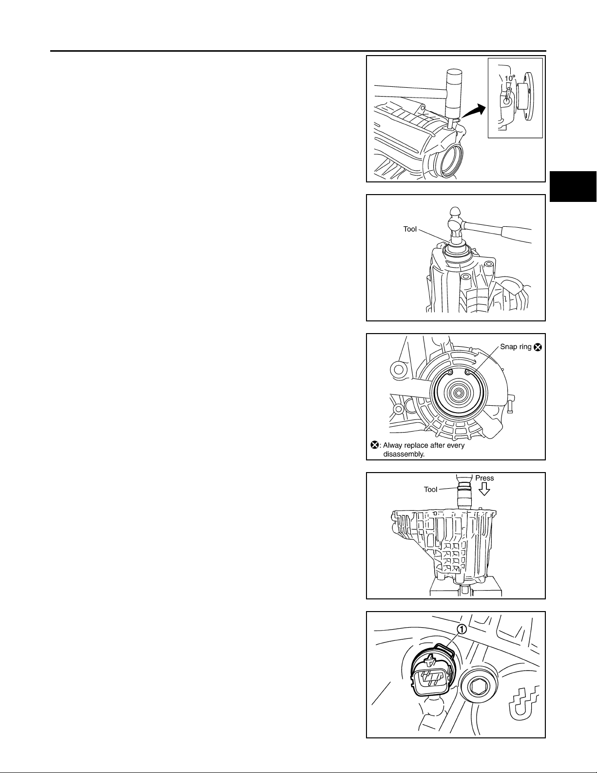
FRONT CASE AND REAR CASE
Revision: October 2006
2007 G35 Sedan
< DISASSEMBLY AND ASSEMBLY >
1. Install breather tube, with plastic hammer.
CAUTION:
Pay attention to the direction of breather tube.
2. Install baffle plate to rear case.
3. Install rear bearing to rear case, using the drift [SST:
KV38104010 ( — )].
CAUTION:
Apply ATF to inside of rear bearing.
[TRANSFER: ETX13B]
A
B
C
PDIA0274E
DLN
E
F
G
PDIA0275E
4. Install snap ring to rear case.
CAUTION:
Never reuse snap ring.
5. Install mainshaft assembly to rear case, using the drift [SST:
ST35321000 ( — )].
CAUTION:
ATF should be applied to contact surface of mainshaft and
rear bearing.
6. Install O-ring to AWD solenoid harness connector.
CAUTION:
• Never reuse O-ring.
• Apply ATF to O-ring.
7. Install AWD solenoid harness connector into rear case.
8. Install retainer (1) to A WD solenoid harness connector.
PDIA0263E
SDIA2368E
H
I
J
K
L
M
N
O
P
JSDIA0100ZZ
DLN-63
Page 64
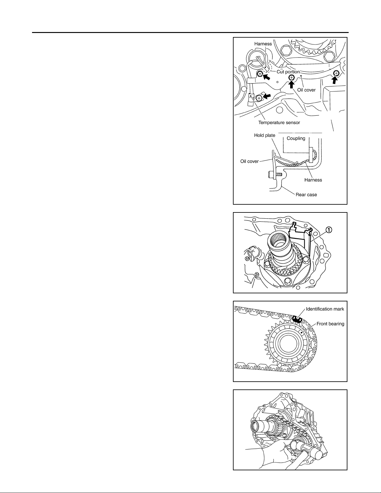
FRONT CASE AND REAR CASE
Revision: October 2006
2007 G35 Sedan
< DISASSEMBLY AND ASSEMBLY >
9. Set temperature sensor and tighten bolt.
10. Hold electric controlled coupling harness with oil cover hold
plate, install oil cover to rear case.
CAUTION:
The harness should be guided by a cut portion.
[TRANSFER: ETX13B]
11. Install oil gutter (1) to rear case.
CAUTION:
The tip of oil gutter should be put into rear case groove.
12. Install drive chain to front drive shaft.
CAUTION:
Identification mark of drive chain should be in the side of
front bearing of front drive shaft.
SDIA2404E
JSDIA0098ZZ
PDIA0284E
13. Install drive chain to mainshaft, and then install tap front drive
shaft with plastic hammer. Press-fit rear bearing of front drive
shaft to rear case.
CAUTION:
Never tap drive chain.
PDIA0257E
DLN-64
Page 65
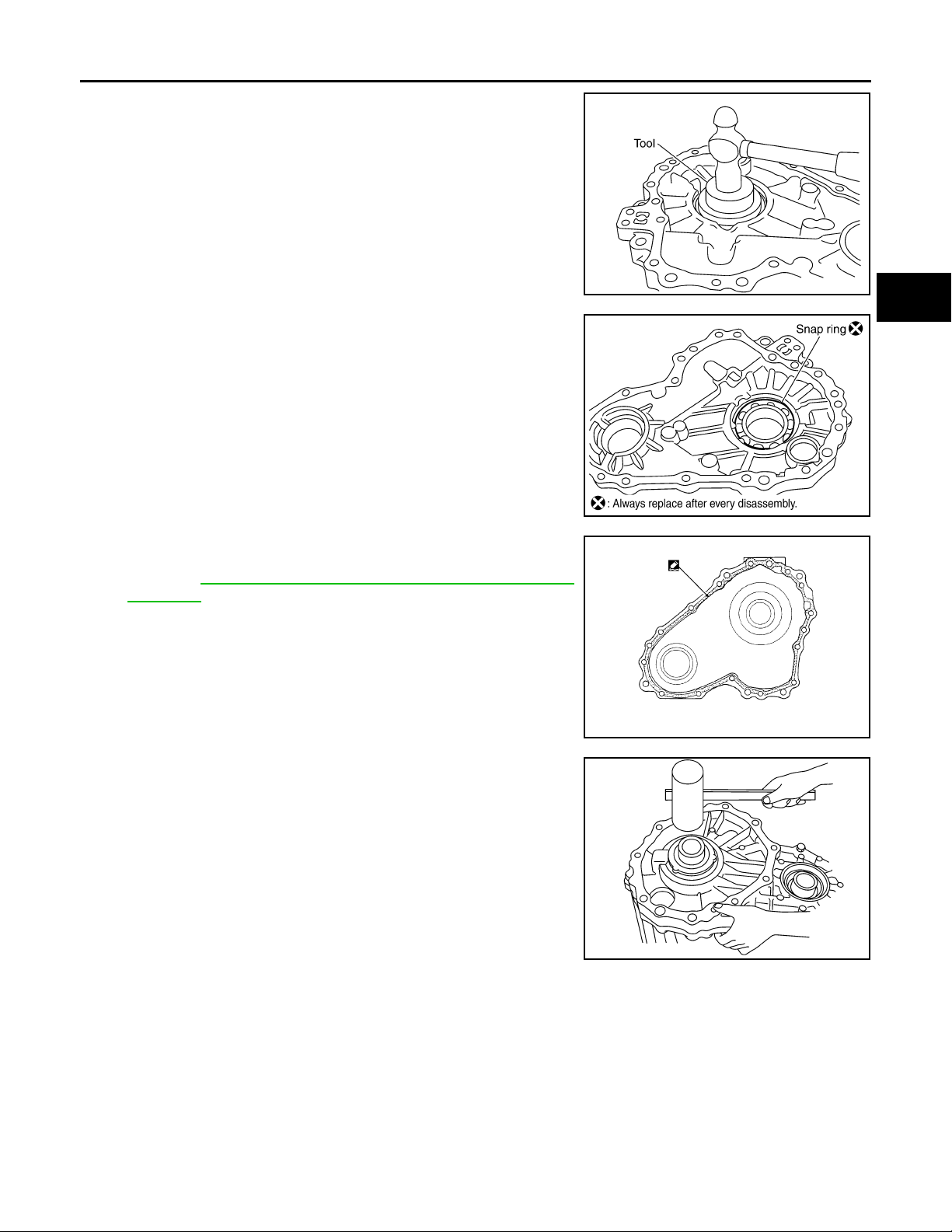
FRONT CASE AND REAR CASE
Revision: October 2006
2007 G35 Sedan
< DISASSEMBLY AND ASSEMBLY >
[TRANSFER: ETX13B]
14. Install mainshaft bearing to front case, using the drift [SST:
ST30621000 (J-25742-5)].
15. Install snap ring to front case.
CAUTION:
Never reuse snap ring.
16. Apply liquid gasket to mating surface of rear case.
• Use Genuine Anaerobic Liquid Gasket or equivalent.
Refer to GI-15, "
Recommended Chemical Products and
Sealants".
CAUTION:
Remove old sealant adhering to mounting surfaces. Also
remove any moisture, oil, or foreign material adhering to
application and mounting surfaces.
PDIA0283E
PDIA0267E
A
B
C
DLN
E
F
G
H
I
J
17. Set front case to rear case.
CAUTION:
Never damage the mating surface transmission side.
PDIA0532J
PDIA0279E
K
L
M
N
O
P
DLN-65
Page 66
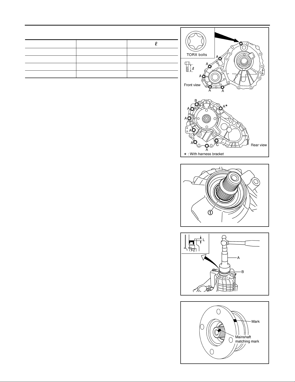
FRONT CASE AND REAR CASE
Revision: October 2006
2007 G35 Sedan
< DISASSEMBLY AND ASSEMBLY >
18. Tighten front case and rear case fixing bolts.
[TRANSFER: ETX13B]
Bolts symbol Quantity
A 11 42 (1.65)
B 1 162 (6.38)
C197 (3.82)
TORX bolts 1 40 (1.57)
19. Install spacer (1) to mainshaft.
CAUTION:
Apply ATF to spacer.
Bolt length “ ” mm (in)
PDIA0251E
20. Install rear oil seal to rear case, using the drifts.
A: Drift [ST30720000 (J-25405)]
B: Drift [KV40104830 ( — )]
Dimension “L” : 6.7 – 7.3 mm (0.264 – 0.287 in)
CAUTION:
• Never reuse rear oil seal.
• Apply ATF to rear oil seal.
• When installing, never incline rear oil seal.
21. Install companion flange while align the matching mark of mainshaft with the mark of companion flange.
JSDIA0097ZZ
JSDIA0168ZZ
SDIA2378E
DLN-66
Page 67
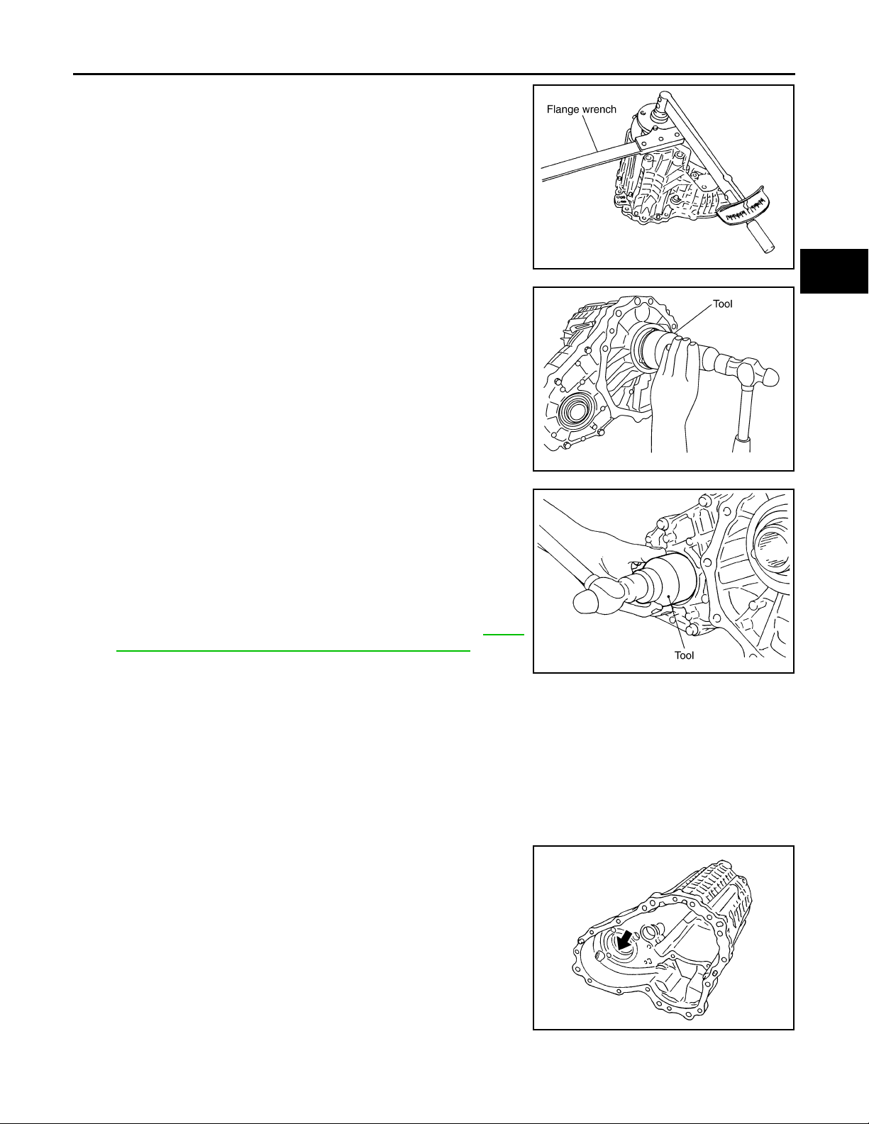
FRONT CASE AND REAR CASE
Revision: October 2006
2007 G35 Sedan
< DISASSEMBLY AND ASSEMBLY >
[TRANSFER: ETX13B]
22. Tighten self-lock nut to the specified torque, with flange wrench.
CAUTION:
Never reuse self-lock nut.
23. Install mainshaft oil seal until it is flush with end face of front
case, using the drift [SST: ST30720000 (J-25405)].
CAUTION:
• Never reuse mainshaft oil seal.
• Apply ATF to mainshaft oil seal.
• When installing, never incline mainshaft oil seal.
24. Install front oil seal until it is flush with end face of front case,
using the drift [SST: ST27862000 ( — )].
CAUTION:
• Never reuse front oil seal.
• Apply ATF to front oil seal.
• When installing, never incline front oil seal.
25. Apply sealant to threads of drain plug. Then install it to rear
case.
• Use Genuine Silicone RTV or equivalent. Refer to GI-15,
"Recommended Chemical Products and Sealants".
CAUTION:
Remove old sealant and oil adhering to threads.
26. Set gasket to filler plug. Install it to rear case.
CAUTION:
• Never reuse gasket.
• After oil is filled, tighten filler plug to specified torque.
SDIA2369E
PDIA0282E
PDIA0287E
A
B
C
DLN
E
F
G
H
I
J
K
L
Inspection INFOID:0000000000957294
Check items below. If necessary, replace them with new ones.
CASES
• Contact surfaces of bearing for wear, damage, etc.
• Damage and cracks of case.
BEARING
M
N
O
P
PDIA0293E
DLN-67
Page 68

FRONT CASE AND REAR CASE
Revision: October 2006
2007 G35 Sedan
< DISASSEMBLY AND ASSEMBLY >
• Damage and rough rotation of bearing.
SHAFT
• Damage, peeling, dent, uneven wear, bending, etc. of shaft.
[TRANSFER: ETX13B]
PDIA0300E
GEARS AND CHAIN
• Excessive wear, damage, peeling, etc. of gear and chain.
PDIA0294E
SDIA2365E
DLN-68
Page 69
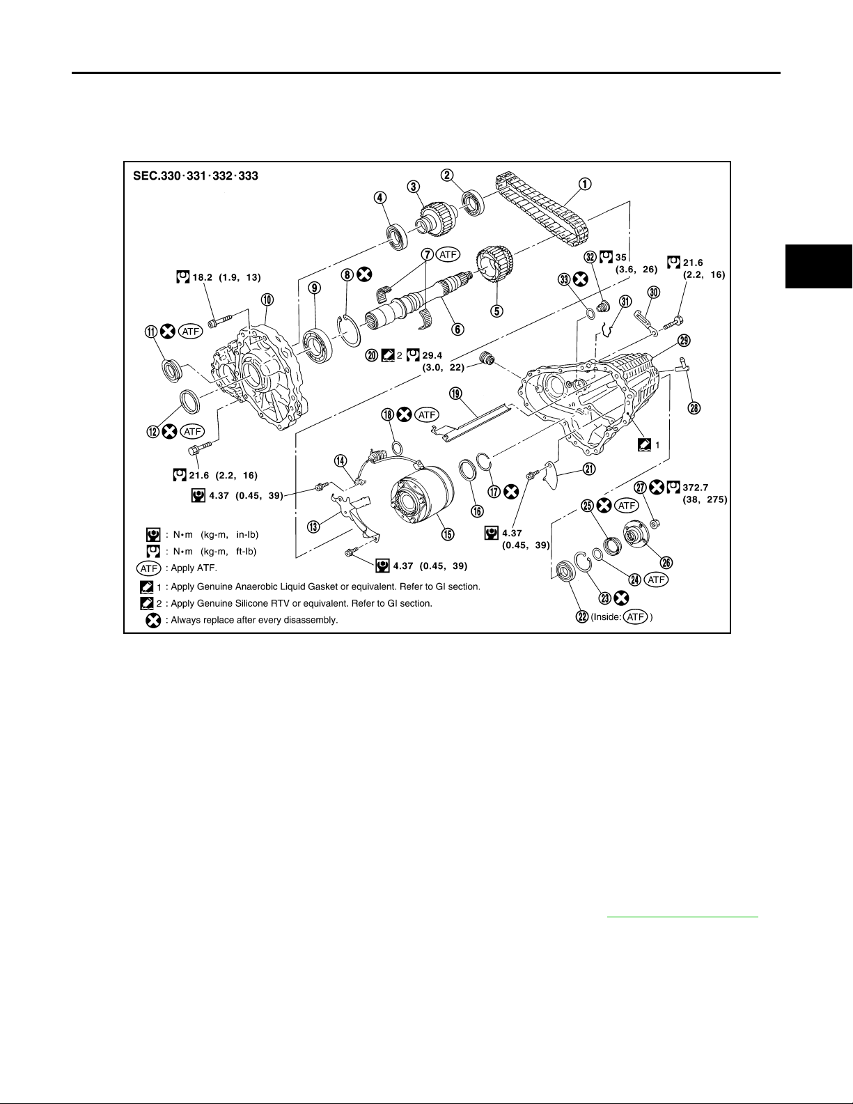
< DISASSEMBLY AND ASSEMBLY >
Revision: October 2006
2007 G35 Sedan
MAINSHAFT
[TRANSFER: ETX13B]
MAINSHAFT
Exploded View INFOID:0000000000957295
A
B
C
DLN
E
F
G
H
PDIA0244E
1. Drive chain 2. Front drive shaft rear bearing 3. Front drive shaft
4. Front drive shaft front bearing 5. Sprocket 6. Mainshaft
7. Needle bearing 8. Snap ring 9. Mainshaft bearing
10. Front case 11. Front oil seal 12. Mainshaft oil seal
13. Oil cover 14. Temperature sensor 15. Electric controlled coupling
16. Spacer 17. Snap ring 18. O-ring
19. Oil gutter 20. Drain plug 21. Baffle plate
22. Re ar be arin g 23. Snap ring 24. Spacer
25. Rear oil seal 26. Companion flange 27. Self-lock nut
28. Breather tube 29. Rear case 30. Harness bracket
31. Retainer 32. Filler plug 33. Gasket
Disassembly INFOID:0000000000957296
1. Separate front case and rear case, then remove mainshaft assembly. Refer to DLN-58, "Disassembly".
I
J
K
L
M
N
O
P
DLN-69
Page 70
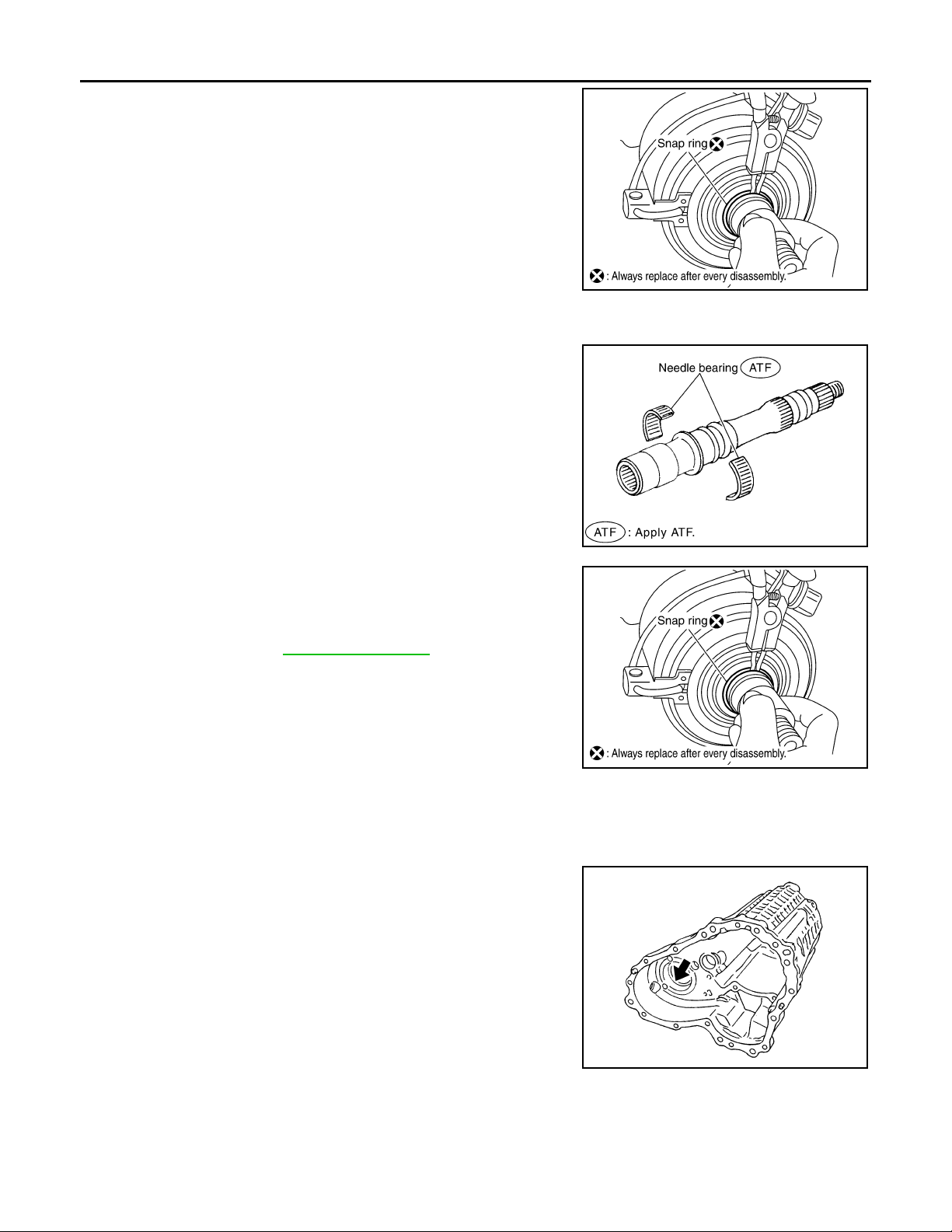
MAINSHAFT
Revision: October 2006
2007 G35 Sedan
< DISASSEMBLY AND ASSEMBLY >
2. Remove snap ring from mainshaft.
3. Remove spacer from mainshaft.
4. Remove electric controlled coupling and sprocket from mainshaft.
5. Remove needle bearing from mainshaft.
[TRANSFER: ETX13B]
SDIA1602E
Assembly INFOID:0000000000957297
1. Install needle bearing to mainshaft.
CAUTION:
Apply ATF to periphery of needle bearing.
2. Install sprocket and electric controlled coupling to mainshaft.
3. Install spacer to main shaft.
PDIA0273E
4. Install snap ring to mainshaft.
CAUTION:
Never reuse snap ring.
5. Install mainshaft assembly to rear case, then install front case
and rear case. Refer to DLN-62, "
Assembly".
SDIA1602E
Inspection INFOID:0000000000957298
Check items below. If necessary, replace them with new ones.
CASES
• Contact surfaces of bearing for wear, damage, etc.
• Damage and cracks of case.
BEARING
PDIA0293E
DLN-70
Page 71
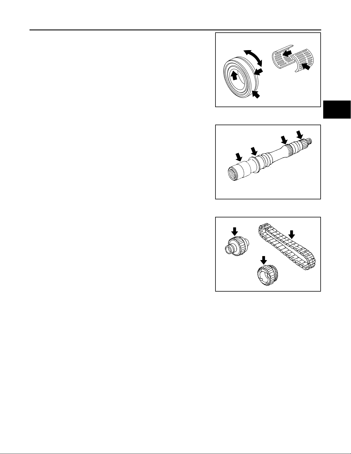
MAINSHAFT
Revision: October 2006
2007 G35 Sedan
< DISASSEMBLY AND ASSEMBLY >
• Damage and rough rotation of bearing.
SHAFT
• Damage, peeling, dent, uneven wear, bending, etc. of shaft.
[TRANSFER: ETX13B]
A
B
C
PDIA0300E
DLN
E
F
G
GEARS AND CHAIN
• Excessive wear, damage, peeling, etc. of gear and chain.
PDIA0294E
SDIA2365E
H
I
J
K
L
M
N
O
P
DLN-71
Page 72
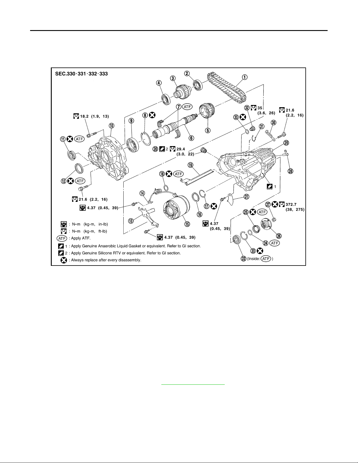
FRONT DRIVE SHAFT AND DRIVE CHAIN
Revision: October 2006
2007 G35 Sedan
< DISASSEMBLY AND ASSEMBLY >
[TRANSFER: ETX13B]
FRONT DRIVE SHAFT AND DRIVE CHAIN
Exploded View INFOID:0000000000957299
PDIA0244E
1. Drive chain 2. Fro nt driv e sh aft rear bear ing 3. Front driv e sh aft
4. Front drive shaft front bearing 5. Sprocket 6. Mainshaft
7. Needle bearing 8. Snap ring 9. Mainshaft bearing
10. Front case 11. Front oil seal 12. Mainshaft oil seal
13. Oil cover 14. Temperature sensor 15. Electric controlled coupling
16. Spacer 17. Snap ring 18. O-ring
19. Oil gutter 20. Drain plug 21. Baffle plate
22. Rear bearing 23. Snap ring 24. Spacer
25. Rear oil seal 26. Companion flange 27. Self-lock nut
28. Breather tube 29. Rear case 30. Harness bracket
31. Retainer 32. Filler plug 33. Gasket
Disassembly INFOID:0000000000957300
1. Separate front case and rear case. Refer to DLN-58, "Disassembly".
DLN-72
Page 73
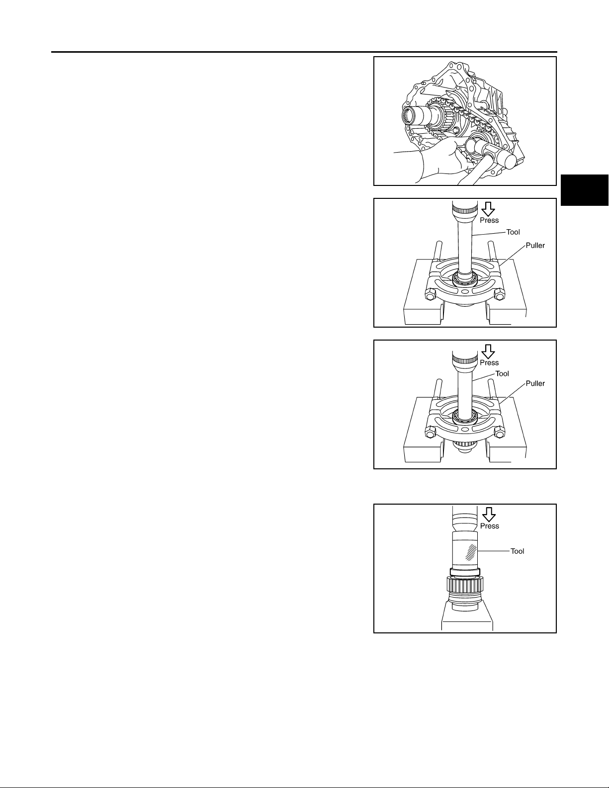
FRONT DRIVE SHAFT AND DRIVE CHAIN
Revision: October 2006
2007 G35 Sedan
< DISASSEMBLY AND ASSEMBLY >
2. Remove drive chain and front drive shaft while tapping front
drive shaft with plastic hammer.
CAUTION:
Never tap drive chain.
3. Remove front drive shaft front bearing, using the drift [SST:
ST31214000 (J-25269-B)] and puller.
[TRANSFER: ETX13B]
A
B
C
PDIA0257E
DLN
E
F
G
PDIA0269E
4. Remove front drive shaft rear bearing, using the drift [SST:
ST31214000 (J-25269-B)] and puller.
PDIA0270E
Assembly INFOID:0000000000957301
1. Install front drive shaft front bearing, using the drift [SST:
ST33200000 (J-26082)].
PDIA0276E
H
I
J
K
L
M
N
O
P
DLN-73
Page 74
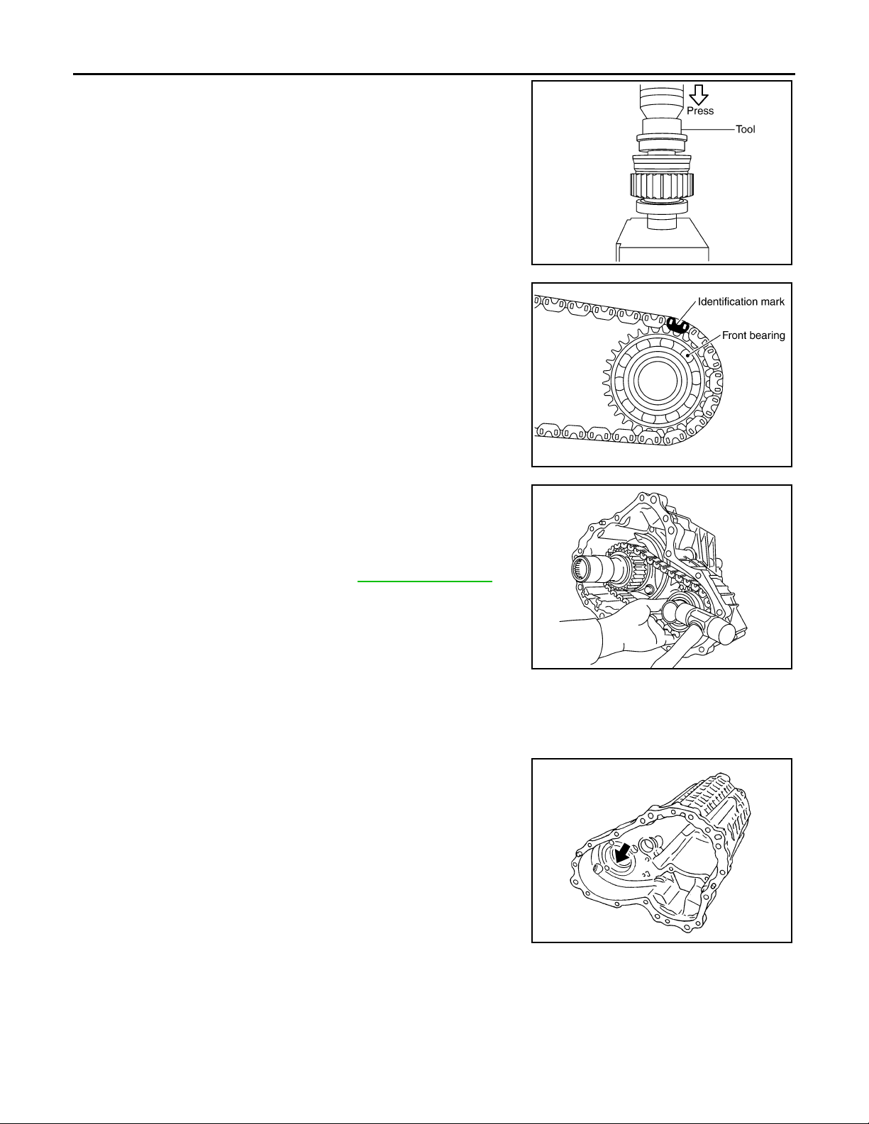
FRONT DRIVE SHAFT AND DRIVE CHAIN
Revision: October 2006
2007 G35 Sedan
< DISASSEMBLY AND ASSEMBLY >
2. Install front drive shaft rear bearing, using the drift [SST:
KV38104010 ( — )].
3. Install drive chain to front drive shaft.
CAUTION:
Identification mark of drive chain should be in the side of
front bearing of front drive shaft.
[TRANSFER: ETX13B]
PDIA0277E
PDIA0284E
4. Install drive chain to mainshaft, and then install tap front drive
shaft with plastic hammer. Press-fit rear bearing of front drive
shaft to rear case.
CAUTION:
Never tap drive chain.
5. Install front case to rear case. Refer to DLN-62, "
Assembly".
PDIA0257E
Inspection INFOID:0000000000957302
Check items below. If necessary, replace them with new ones.
CASES
• Contact surfaces of bearing for wear, damage, etc.
• Damage and cracks of case.
BEARING
PDIA0293E
DLN-74
Page 75
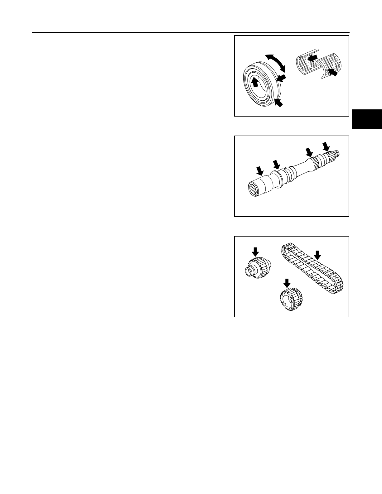
FRONT DRIVE SHAFT AND DRIVE CHAIN
Revision: October 2006
2007 G35 Sedan
< DISASSEMBLY AND ASSEMBLY >
• Damage and rough rotation of bearing.
SHAFT
• Damage, peeling, dent, uneven wear, bending, etc. of shaft.
[TRANSFER: ETX13B]
A
B
C
PDIA0300E
DLN
E
F
G
GEARS AND CHAIN
• Excessive wear, damage, peeling, etc. of gear and chain.
PDIA0294E
SDIA2365E
H
I
J
K
L
M
N
O
P
DLN-75
Page 76
SERVICE DATA AND SPECIFICATIONS (SDS)
Revision: October 2006
2007 G35 Sedan
< SERVICE DATA AND SPECIFICATIONS (SDS)
[TRANSFER: ETX13B]
SERVICE DATA AND SPECIFICATIONS (SDS)
SERVICE DATA AND SPECIFICATIONS (SDS)
General Specifications INFOID:0000000000957303
AWD
Applied model
Transfer model ETX13B
Fluid capacity (Approx.)
(US pt, lmp pt)
VQ35HR
A/T
1.25 (2-5/8, 2-1/4)
DLN-76
Page 77
NOISE, VIBRATION AND HARSHNESS (NVH) TROUBLESHOOTING
Revision: October 2006
2007 G35 Sedan
< SYMPTOM DIAGNOSIS >
[FRONT PROPELLER SHAFT: 2S56A]
SYMPTOM DIAGNOSIS
NOISE, VIBRATION AND HARSHNESS (NVH) TROUBLESHOOTING
NVH Troubleshooting Chart INFOID:0000000000957304
Use the chart below to help you find the cause of the symptom. If necessary, repair or replace these parts.
Reference
—
—
—
—
Inspection"
DLN-79, "Inspection"
DLN-81, "
DLN-81, "Inspection"
NVH in DLN section.
NVH in FAX, RAX, FSU and RSU section.
NVH in WT section.
NVH in WT section.
NVH in RAX section.
NVH in BR section.
NVH in ST section.
A
B
C
DLN
E
F
G
H
Possible cause and SUSPECTED PARTS
Noise ЧЧЧЧЧЧЧЧЧЧЧЧЧЧ
Symptom
×: Applicable
Shake × × ЧЧЧЧЧЧ
Vibration ЧЧЧЧЧЧЧ ×× × ×
I
J
K
L
M
Uneven rotating torque
Center bearing improper installation
Excessive center bearing axial end play
Center bearing mounting (insulator) cr acks, damage or deterioration
Excessive joint angle
Rotation imbalance
Excessive runout
DIFFERENTIAL
AXLE AND SUSPENSION
TIRES
ROAD WHEEL
DRIVE SHAFT
BRAKES
STEERING
N
O
P
DLN-77
Page 78
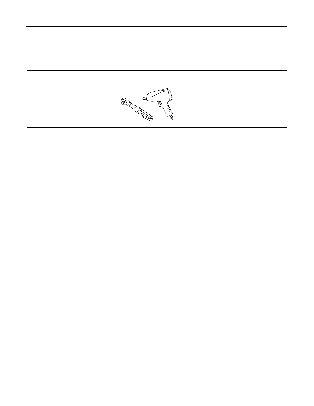
PREPARATION
Revision: October 2006
2007 G35 Sedan
< PREPARATION >
[FRONT PROPELLER SHAFT: 2S56A]
PREPARATION
PREPARATION
Commercial Service Tools INFOID:0000000000957305
Tool name Description
Power tool Loosening bolts and nuts
PBIC0190E
DLN-78
Page 79
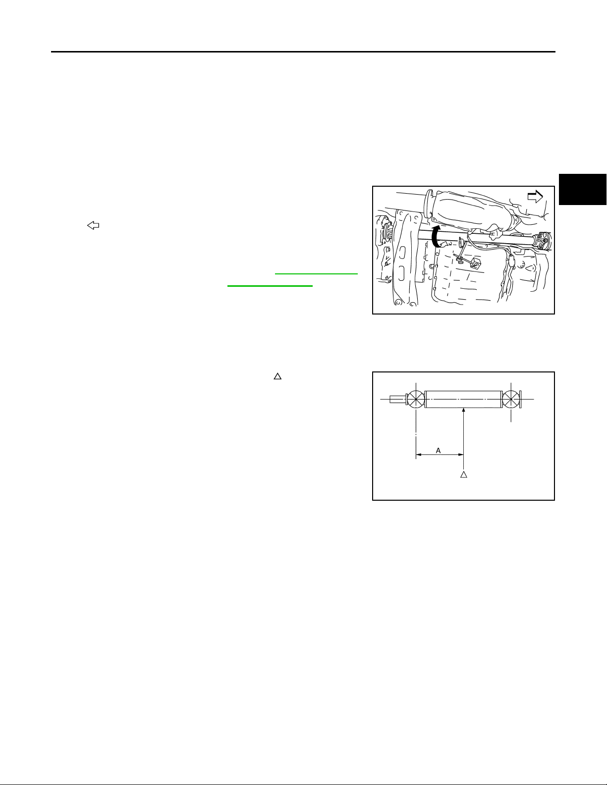
< ON-VEHICLE MAINTENANCE >
Revision: October 2006
2007 G35 Sedan
FRONT PROPELLER SHAFT
[FRONT PROPELLER SHAFT: 2S56A]
ON-VEHICLE MAINTENANCE
FRONT PROPELLER SHAFT
Inspection INFOID:0000000000957306
NOISE
• Check the propeller shaft tube surface for dents or cracks. If damaged, replace propeller shaft assembly.
VIBRATION
• If vibration is present at high speed, inspect propeller shaft runout first.
1. Measure propeller shaft runout at several points by rotating final
drive companion flange with hands.
: Vehicle front
Limit
Propeller shaft runout : Refer to DLN-82, "
ler Shaft Runout".
2. If runout still exceeds specifications, separate propeller shaft at
final drive companion flange; then rotate companion flange 90,
180, 270 degrees and install propeller shaft.
3. Check runout again. If runout still exceeds specifications, replace propeller shaft assembly.
4. Check the vibration by driving vehicle.
RUNOUT MEASURING POINT
• Propeller shaft runout measuring point (Point “ ”).
Dimension A: 381.5 mm (15.02 in)
Propel-
PDIA0767J
A
B
C
DLN
E
F
G
H
I
PDIA0768J
J
K
L
M
N
O
P
DLN-79
Page 80
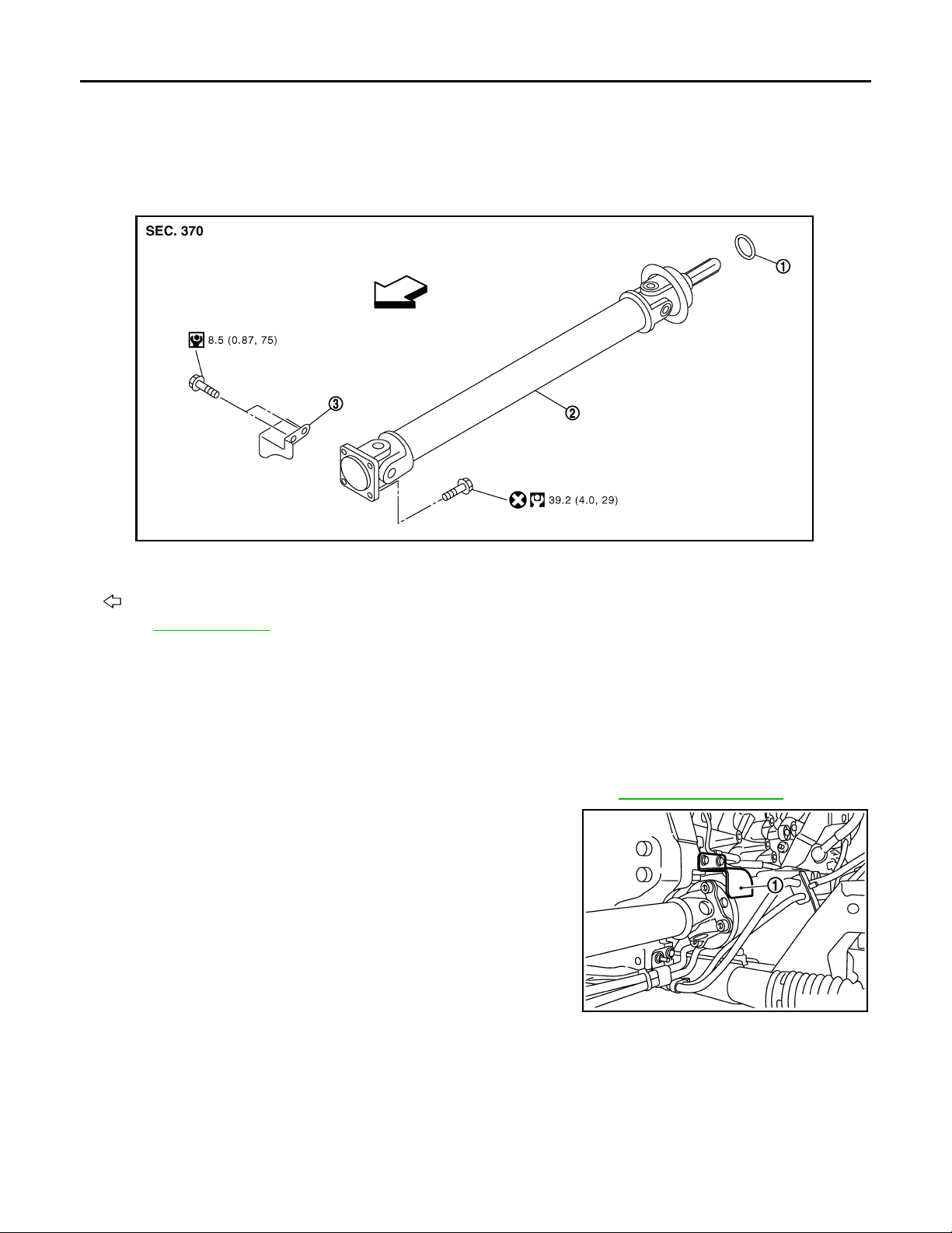
FRONT PROPELLER SHAFT
Revision: October 2006
2007 G35 Sedan
< ON-VEHICLE REPAIR >
[FRONT PROPELLER SHAFT: 2S56A]
ON-VEHICLE REPAIR
FRONT PROPELLER SHAFT
Exploded View INFOID:0000000000957307
JSDIA0001GB
1. O-ring 2. Propeller shaft assembly 3. Heat bracket
: Vehicle front
Refer to GI-4, "
Components" for symbols in the figure.
Removal and Installation INFOID:0000000000957308
REMOVAL
1. Move the A/T selector lever to N position and release the parking brake.
2. Remove engine undercover with a power tool.
3. Remove front cross bar.
4. Remove the three way catalyst (right bank) with a power tool. Refer to EX-5, "
5. Remove heat bracket (1).
Exploded View".
JSDIA0013ZZ
DLN-80
Page 81
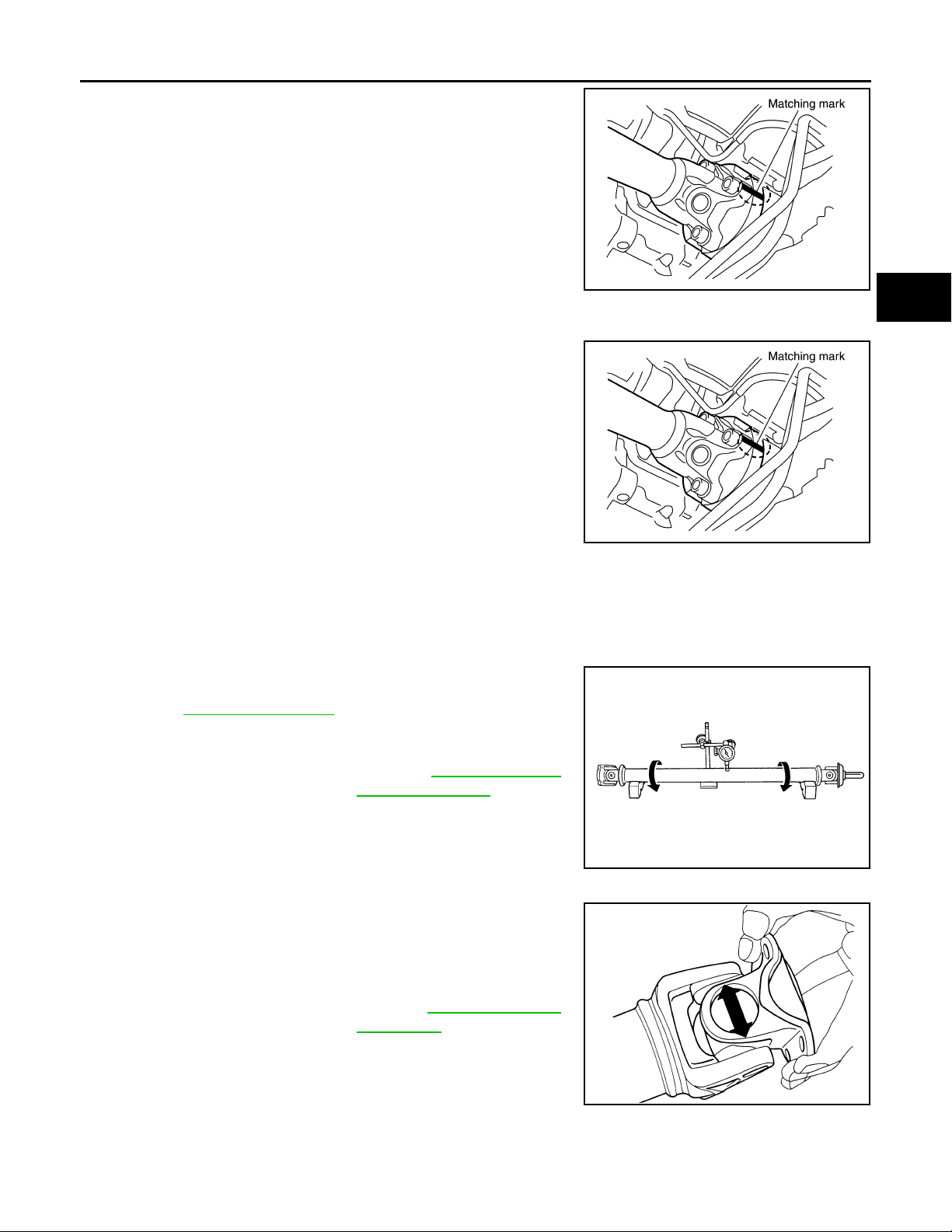
FRONT PROPELLER SHAFT
Revision: October 2006
2007 G35 Sedan
< ON-VEHICLE REPAIR >
6. Put matching marks onto propeller shaft flange yoke and final
drive companion flange.
CAUTION:
For matching marks, use paint. Never damage propeller
shaft flange and final drive companion flange.
7. Remove the propeller shaft assembly fixing bolts.
8. Remove propeller shaft assembly from the front final drive and
transfer.
CAUTION:
Never damage the transfer front oil seal.
INSTALLATION
Note the following, and install in the reverse order of removal.
• Align matching marks to install propeller shaft assembly to final
drive companion flange.
• After assembly, perform a driving test to check propeller shaft
vibration. If vibration occurred, separate propeller shaft from final
drive or transfer. Reinstall companion flange after rotating it by 90,
180, 270 degrees. Then perform driving test and check propeller
shaft vibration again at each point.
CAUTION:
Never damage the transfer front oil seal.
[FRONT PROPELLER SHAFT: 2S56A]
A
B
C
SDIA1517E
DLN
E
F
G
SDIA1517E
Inspection INFOID:0000000000957309
APPEARANCE
Check propeller shaft for bend and damage. If damage is detected, replace propeller shaft assembly.
PROPELLER SHAFT RUNOUT
Check propeller shaft runout at measuring point. If runout exceeds
specifications, replace propeller shaft assembly. For measuring
point, refer to DLN-79, "
Limit
Propeller shaft runout : Refer to DLN-82, "
JOURNAL AXIAL PLAY
As shown in the figure, while fixing yoke on one side, check axial
play of joint. If outside the standard, replace propeller shaft assembly.
Standard
Journal axial play : Refer to DLN-82, "
CAUTION:
Never disassemble joints.
Inspection".
Propel-
ler Shaft Runout".
JSDIA0083ZZ
Journal
Axial Play".
PDA0005D
H
I
J
K
L
M
N
O
P
DLN-81
Page 82
SERVICE DATA AND SPECIFICATIONS (SDS)
Revision: October 2006
2007 G35 Sedan
< SERVICE DATA AND SPECIFICATIONS (SDS)
[FRONT PROPELLER SHAFT: 2S56A]
SERVICE DATA AND SPECIFICATIONS (SDS)
SERVICE DATA AND SPECIFICATIONS (SDS)
General Specifications INFOID:0000000000957310
AWD
Applied model
Propeller shaft model 2S56A
Number of joints 2
Type of journal bearings
(Non-disassembly type)
Coupling method with transfer Sleeve type
Coupling method with front final drive Flange type
Shaft length (Spider to spider) 763 mm (30.04 in)
Shaft outer diameter 42.7 mm (1.68 in)
Propeller Shaft Runout INFOID:0000000000957311
VQ35HR
A/T
Shell type
Unit: mm (in)
Item Limit
Propeller shaft runout 0.8 (0.031)
Journal Axial Play INFOID:0000000000957312
Unit: mm (in)
Item Standard
Journal axial play 0 (0)
DLN-82
Page 83
NOISE, VIBRATION AND HARSHNESS (NVH) TROUBLESHOOTING
Revision: October 2006
2007 G35 Sedan
< SYMPTOM DIAGNOSIS >
[REAR PROPELLER SHAFT: 3S80A]
SYMPTOM DIAGNOSIS
NOISE, VIBRATION AND HARSHNESS (NVH) TROUBLESHOOTING
NVH Troubleshooting Chart INFOID:0000000000957313
Use the chart below to help you find the cause of the symptom. If necessary, repair or replace these parts.
Reference
DLN-85, "Inspection"
—
DLN-88, "Inspection"
—
Inspection"
DLN-88, "
Inspection"
DLN-88, "
DLN-88, "Inspection"
NVH in DLN section.
NVH in FAX, RAX, FSU and RSU section.
NVH in WT section.
NVH in WT section.
NVH in RAX section.
NVH in BR section.
NVH in ST section.
A
B
C
DLN
E
F
G
H
Possible cause and SUSPECTED PARTS
Noise ЧЧЧЧЧЧЧЧЧЧЧЧЧЧ
Symptom
×: Applicable
Shake × × ЧЧЧЧЧЧ
Vibration ЧЧЧЧЧЧЧ ×× × ×
I
J
K
L
M
Uneven rotating torque
Center bearing improper installation
Excessive center bearing axial end play
Center bearing mounting (insulator) cr acks, damage or deterioration
Excessive joint angle
Rotation imbalance
Excessive runout
DIFFERENTIAL
AXLE AND SUSPENSION
TIRES
ROAD WHEEL
DRIVE SHAFT
BRAKES
STEERING
N
O
P
DLN-83
Page 84
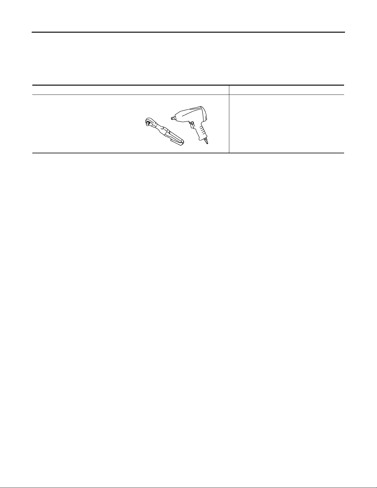
PREPARATION
Revision: October 2006
2007 G35 Sedan
< PREPARATION >
[REAR PROPELLER SHAFT: 3S80A]
PREPARATION
PREPARATION
Commercial Service Tools INFOID:0000000000957314
Tool name Description
Power tool Loosening bolts and nuts
PBIC0190E
DLN-84
Page 85
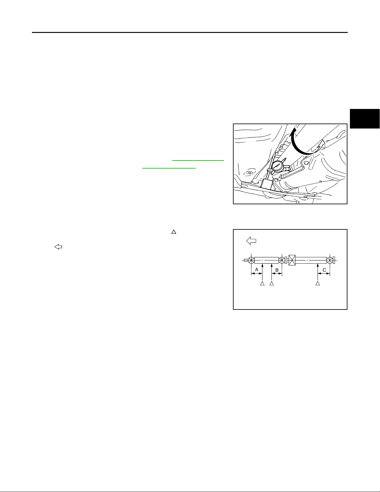
< ON-VEHICLE MAINTENANCE >
Revision: October 2006
2007 G35 Sedan
REAR PROPELLER SHAFT
[REAR PROPELLER SHAFT: 3S80A]
ON-VEHICLE MAINTENANCE
REAR PROPELLER SHAFT
Inspection INFOID:0000000000957315
NOISE
• Check the propeller shaft tube surface for dents or cracks. If damaged, replace propeller shaft assembly.
• If center bearing is noisy or damaged, replace propeller shaft assembly.
VIBRATION
• If vibration is present at high speed, inspect propeller shaft runout first.
1. Measure propeller shaft runout at several points by rotating final
drive companion flange with hands.
Limit
Propeller shaft runout : Refer to DLN-89, "
ler Shaft Runout".
2. If runout still exceeds specifications, separate propeller shaft at
final drive companion flange; then rotate companion flange 90,
180, 270 degrees and install propeller shaft.
3. Check runout again. If runout still exceeds specifications,
replace propeller shaft assembly.
4. Check the vibration by driving vehicle.
RUNOUT MEASURING POINT
• Propeller shaft runout measuring point (Point “ ”).
Propel-
SDIA1087E
A
B
C
DLN
E
F
G
H
: Vehicle front
Dimension A: 192 mm (7.56 in)
B: 172 mm (6.77 in)
C: 170 mm (6.69 in)
I
J
K
PDIA0770J
L
M
N
O
P
DLN-85
Page 86
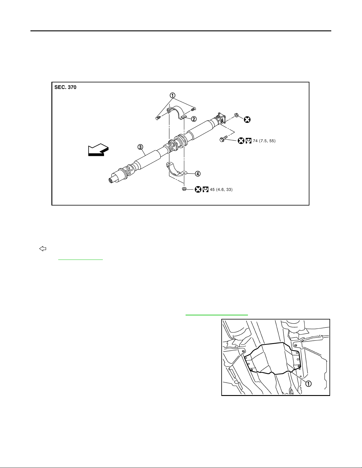
REAR PROPELLER SHAFT
Revision: October 2006
2007 G35 Sedan
< ON-VEHICLE REPAIR >
[REAR PROPELLER SHAFT: 3S80A]
ON-VEHICLE REPAIR
REAR PROPELLER SHAFT
Exploded View INFOID:0000000000957316
JSDIA0124GB
1. Clip 2. Center bearing mounting bracket
(Upper)
4. Center bearing mounting bracket
(Lower)
: Vehicle front
Refer to GI-4, "
Components" for symbols in the figure.
3. Propeller shaft assembly
Removal and Installation INFOID:0000000000957317
REMOVAL
1. Move the M/T shift lever to neutral position and release the parking brake.
2. Remove the floor reinforcement.
3. Remove the center muffler with power tool. Refer to EX-5, "
4. Remove the heat plate (1).
Exploded View".
JSDIA0006ZZ
DLN-86
Page 87
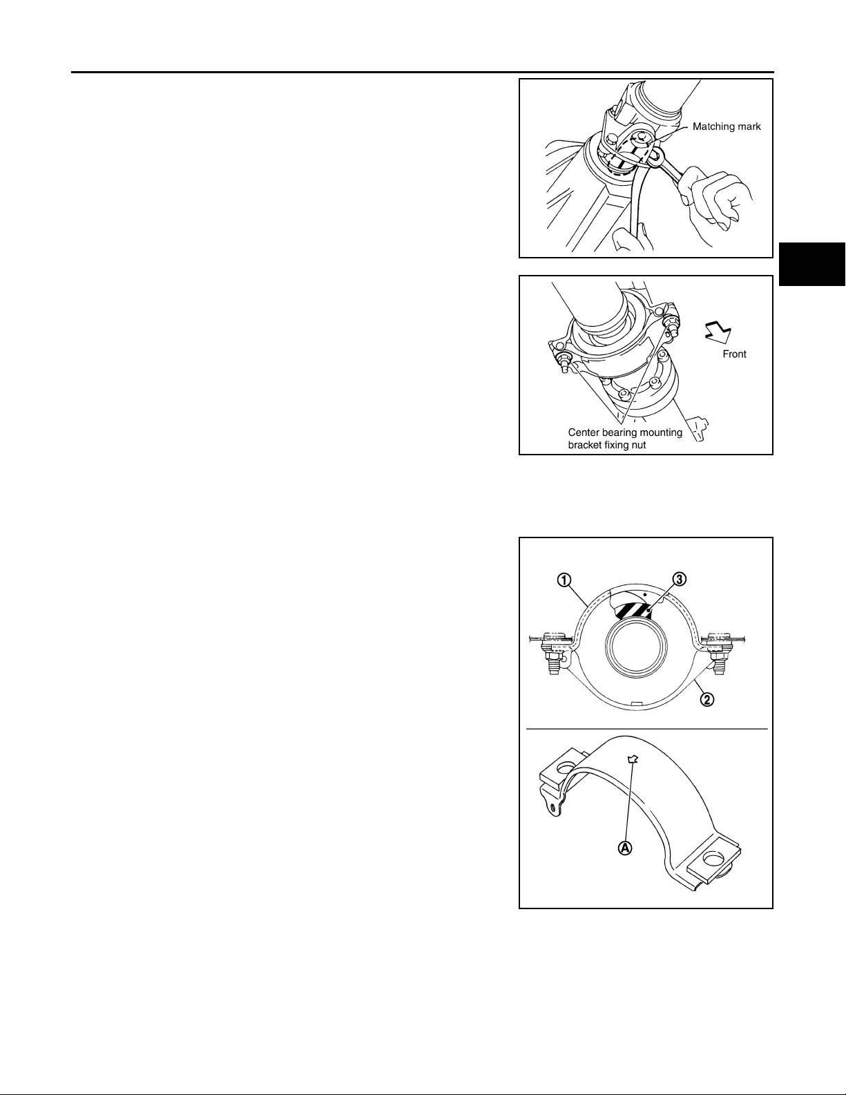
REAR PROPELLER SHAFT
Revision: October 2006
2007 G35 Sedan
< ON-VEHICLE REPAIR >
5. Put matching marks on propeller shaft flange yoke with final
drive companion flange.
CAUTION:
For matching marks, use paint. Never damage propeller
shaft flange yoke and final drive companion flange.
6. Loosen mounting nuts of center bearing mounting brackets.
CAUTION:
Tighten mounting nuts temporarily.
7. Remove propeller shaft assembly fixing bolts and nuts.
8. Remove center bearing mounting bracket fixing nuts.
9. Remove propeller shaft assembly.
CAUTION:
• Never damage the rear oil seal of transmission.
• If constant velocity joint was bent during propeller shaft
assembly removal, installation, or transportation, its boot
may be damaged. Wrap boot interference area to metal
part with shop cloth or rubber to protect boot from breakage.
[REAR PROPELLER SHAFT: 3S80A]
A
B
C
SDIA1822E
DLN
E
F
G
PDIA0402E
H
INSTALLATION
Note the following, and install in the reverse order of removal.
• Install center bearing mounting bracket (Upper) (1) with its arrow
mark (A) facing forward.
• Adjust position of center bearing mounting bracket (1, 2) sliding
back and forth to prevent play in thrust direction of center bearing
insulator (3). Install bracket to vehicle.
I
J
K
L
M
N
O
JSDIA0127ZZ
P
DLN-87
Page 88
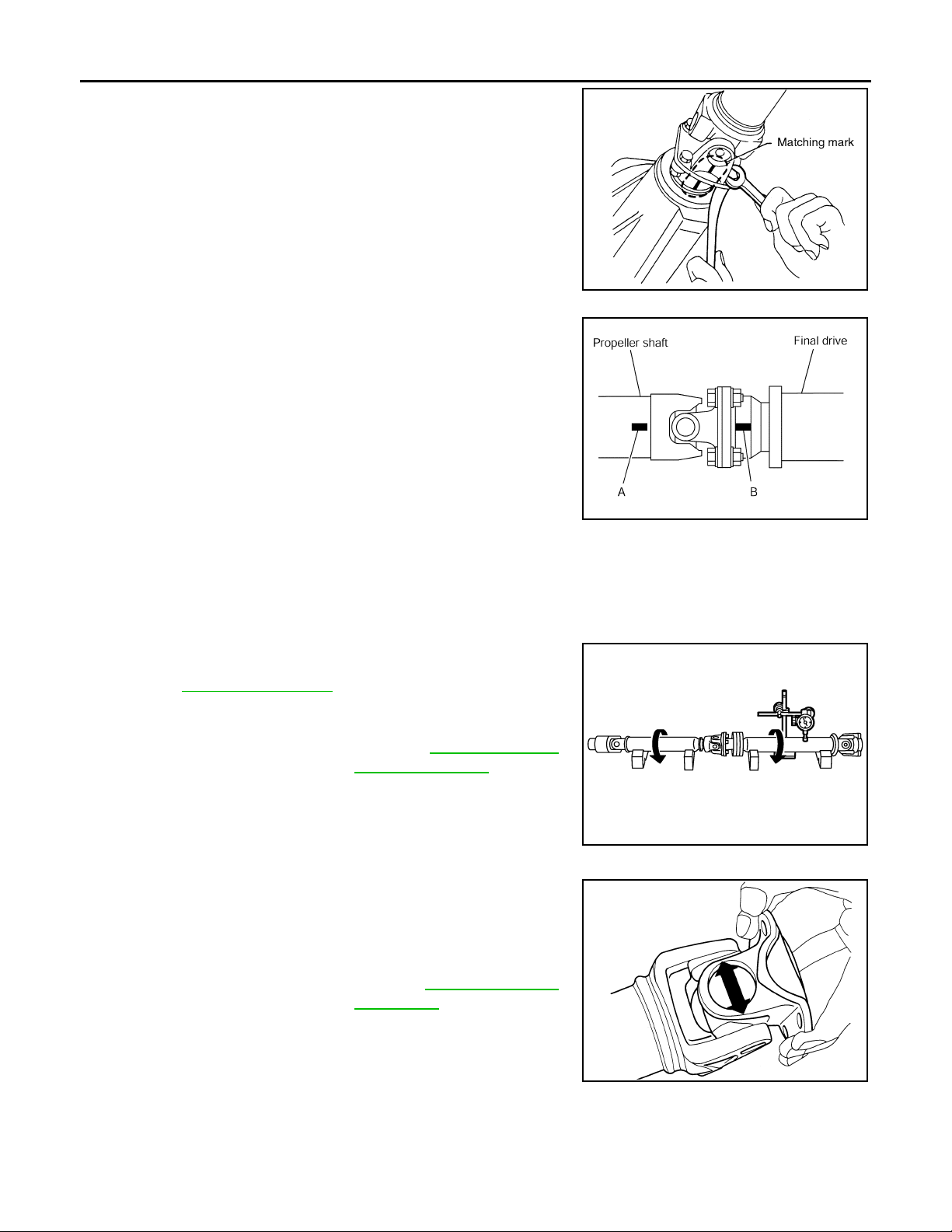
REAR PROPELLER SHAFT
Revision: October 2006
2007 G35 Sedan
< ON-VEHICLE REPAIR >
• Align matching marks to install propeller shaft flange yoke with final
drive companion flange.
• After assembly, perform a driving test to check propeller shaft
vibration. If vibration occurred, separate propeller shaft from final
drive. Reinstall companion flange after rotating it by 90, 180, 270
degrees. Then perform driving test and check propeller shaft vibration again at each point.
• If propeller shaft or final drive has been replaced, connect them as
follows:
- Install the propeller shaft while aligning its matching mark (A) with
the matching mark (B) on the joint as close as possible.
CAUTION:
Never damage the rear oil seal of transmission.
[REAR PROPELLER SHAFT: 3S80A]
SDIA1822E
PDIA0423E
Inspection INFOID:0000000000957318
APPEARANCE
Check propeller shaft for bend and damage. If damage is detected, replace propeller shaft assembly.
PROPELLER SHAFT RUNOUT
Check propeller shaft runout at measuring points. If runout exceeds
specifications, replace propeller shaft assembly. For measuring
point, refer to DLN-85, "
Limit
Propeller shaft runout : Refer to DLN-89, "
JOURNAL AXIAL PLAY
As shown in the figure, while fixing yoke on one side, check axial
play of joint. If outside the standard, replace propeller shaft assembly.
Standard
Journal axial play : Refer to DLN-89, "
Inspection".
Propel-
ler Shaft Runout".
JSDIA0111ZZ
Journal
Axial Play".
CAUTION:
Never disassemble joints.
CENTER BEARING
Check center bearing for noise and damage. If noise or damage is detected, replace propeller shaft assembly.
CAUTION:
Never disassemble center bearing.
PDA0005D
DLN-88
Page 89
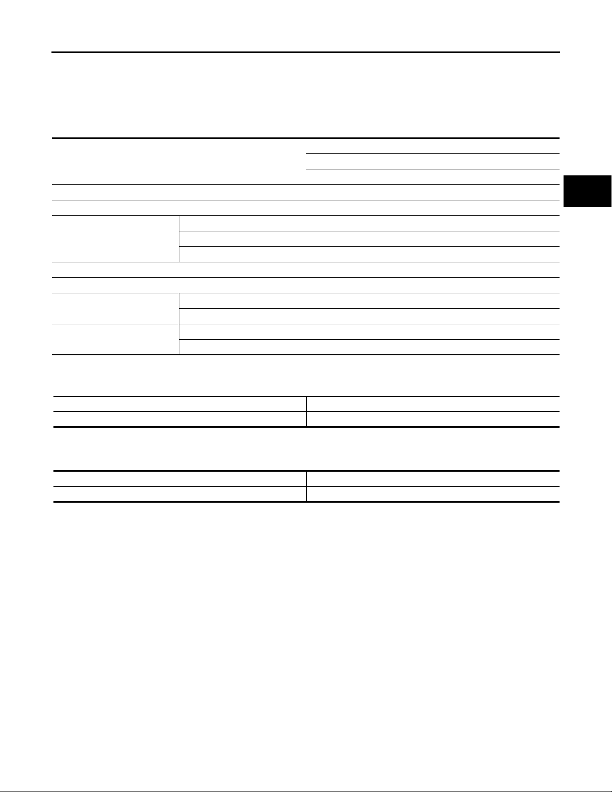
SERVICE DATA AND SPECIFICATIONS (SDS)
Revision: October 2006
2007 G35 Sedan
< SERVICE DATA AND SPECIFICATIONS (SDS)
[REAR PROPELLER SHAFT: 3S80A]
SERVICE DATA AND SPECIFICATIONS (SDS)
SERVICE DATA AND SPECIFICATIONS (SDS)
General Specifi cati ons INFOID:0000000000957319
2WD
Applied model
Propeller shaft model 3S80A
Number of joints 3
1st joint Shell type
Type of jo urnal bearings
(Non-disassembly type)
Coupling method with transmission Sleeve type
Coupling method with rear final drive Flange type
Shaft length
Shaft outer diameter
2nd joint Shell type
3rd joint Shell type
1st (Spider to spider) 762 mm (30.00 in)
2nd (Spider to spider) 759 mm (29.88 in)
1st 82.6 mm (3.25 in)
2nd 75.0 mm (2.95 in)
Propeller Shaft Runout INFOID:0000000000957320
VQ35HR
M/T
A
B
C
DLN
E
F
G
H
Unit: mm (in)
Item Limit
Propeller shaft runout 0.8 (0.031)
Journal Axial Play INFOID:0000000000957321
Unit: mm (in)
Item Standard
Journal axial play 0 (0)
I
J
K
L
M
N
O
P
DLN-89
Page 90
NOISE, VIBRATION AND HARSHNESS (NVH) TROUBLESHOOTING
Revision: October 2006
2007 G35 Sedan
< SYMPTOM DIAGNOSIS >
[REAR PROPELLER SHAFT: 3S80A-R]
SYMPTOM DIAGNOSIS
NOISE, VIBRATION AND HARSHNESS (NVH) TROUBLESHOOTING
NVH Troubleshooting Chart INFOID:0000000000957322
Use the chart below to help you find the cause of the symptom. If necessary, repair or replace these parts.
Reference
Possible cause and SUSPECTED PARTS
—
DLN-92, "Inspection"
DLN-96, "Inspection"
—
Inspection"
DLN-96, "
Inspection"
DLN-96, "
DLN-96, "Inspection"
NVH in DLN section.
NVH in FAX, RAX, FSU and RSU section.
NVH in WT section.
NVH in WT section.
NVH in RAX section.
NVH in BR section.
NVH in ST section.
Symptom
×: Applicable
Uneven rotating torque
Center bearing improper installation
Excessive center bearing axial end play
Center bearing mounting (insulator) cr acks, damage or deterioration
Excessive joint angle
Rotation imbalance
Excessive runout
DIFFERENTIAL
AXLE AND SUSPENSION
TIRES
ROAD WHEEL
DRIVE SHAFT
BRAKES
STEERING
Noise ЧЧЧЧЧЧЧЧЧЧЧЧЧЧ
Shake × × ЧЧЧЧЧЧ
Vibration ЧЧЧЧЧЧЧ ×× × ×
DLN-90
Page 91
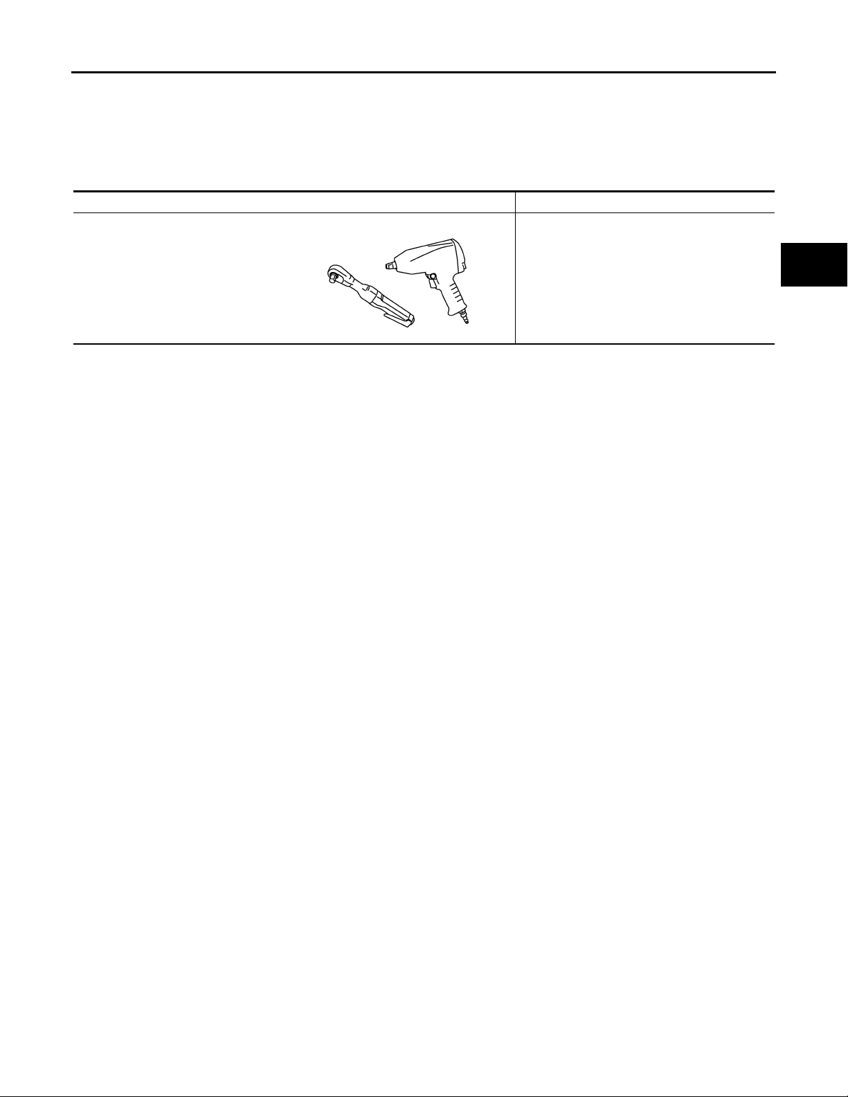
< PREPARATION >
Revision: October 2006
2007 G35 Sedan
PREPARATION
[REAR PROPELLER SHAFT: 3S80A-R]
PREPARATION
PREPARATION
Commercial Service Tools INFOID:0000000000957323
Tool name Description
Power tool Loosening bolts and nuts
PBIC0190E
A
B
C
DLN
E
F
G
H
K
M
N
O
P
I
J
L
DLN-91
Page 92
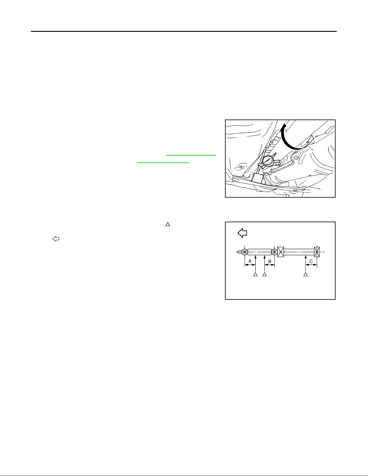
REAR PROPELLER SHAFT
Revision: October 2006
2007 G35 Sedan
< ON-VEHICLE MAINTENANCE >
[REAR PROPELLER SHAFT: 3S80A-R]
ON-VEHICLE MAINTENANCE
REAR PROPELLER SHAFT
Inspection INFOID:0000000000957324
NOISE
• Check the propeller shaft tube surface for dents or cracks. If damaged, replace propeller shaft assembly.
• If center bearing is noisy or damaged, replace propeller shaft assembly.
VIBRATION
• If vibration is present at high speed, inspect propeller shaft runout first.
1. Measure propeller shaft runout at several points by rotating final
drive companion flange with hands.
Limit
Propeller shaft runout : Refer to DLN-97, "
ler Shaft Runout".
2. If runout still exceeds specifications, separate propeller shaft at
final drive companion flange; then rotate companion flange 120,
240 degrees and install propeller shaft.
3. Check runout again. If runout still exceeds specifications,
replace propeller shaft assembly.
4. Check the vibration by driving vehicle.
Propel-
SDIA1087E
RUNOUT MEASURING POINT
• Propeller shaft runout measuring point (Point “ ”).
: Vehicle front
Dimension A: 192 mm (7.56 in)
B: 172 mm (6.77 in)
C: 172 mm (6.77 in)
JSDIA0169ZZ
DLN-92
Page 93
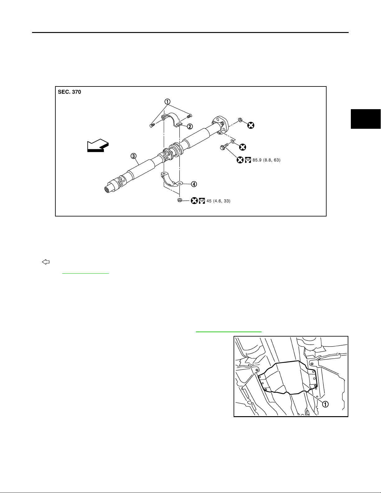
< ON-VEHICLE REPAIR >
Revision: October 2006
2007 G35 Sedan
REAR PROPELLER SHAFT
[REAR PROPELLER SHAFT: 3S80A-R]
ON-VEHICLE REPAIR
REAR PROPELLER SHAFT
Exploded View INFOID:0000000000957325
JSDIA0007GB
1. Clip 2. Center bearing mounting bracket
(Upper)
4. Center bearing mounting bracket
(Lower)
3. Propeller shaft assembly
A
B
C
DLN
E
F
G
H
I
: Vehicle front
Refer to GI-4, "
Components" for symbols in the figure.
Removal and Installation INFOID:0000000000957326
REMOVAL
1. Move the A/T selector lever to N position and release the parking brake.
2. Remove the floor reinforcement.
3. Remove the center muffler with power tool. Refer to EX-5, "
4. Remove the heat plate (1).
Exploded View".
JSDIA0006ZZ
J
K
L
M
N
O
P
DLN-93
Page 94
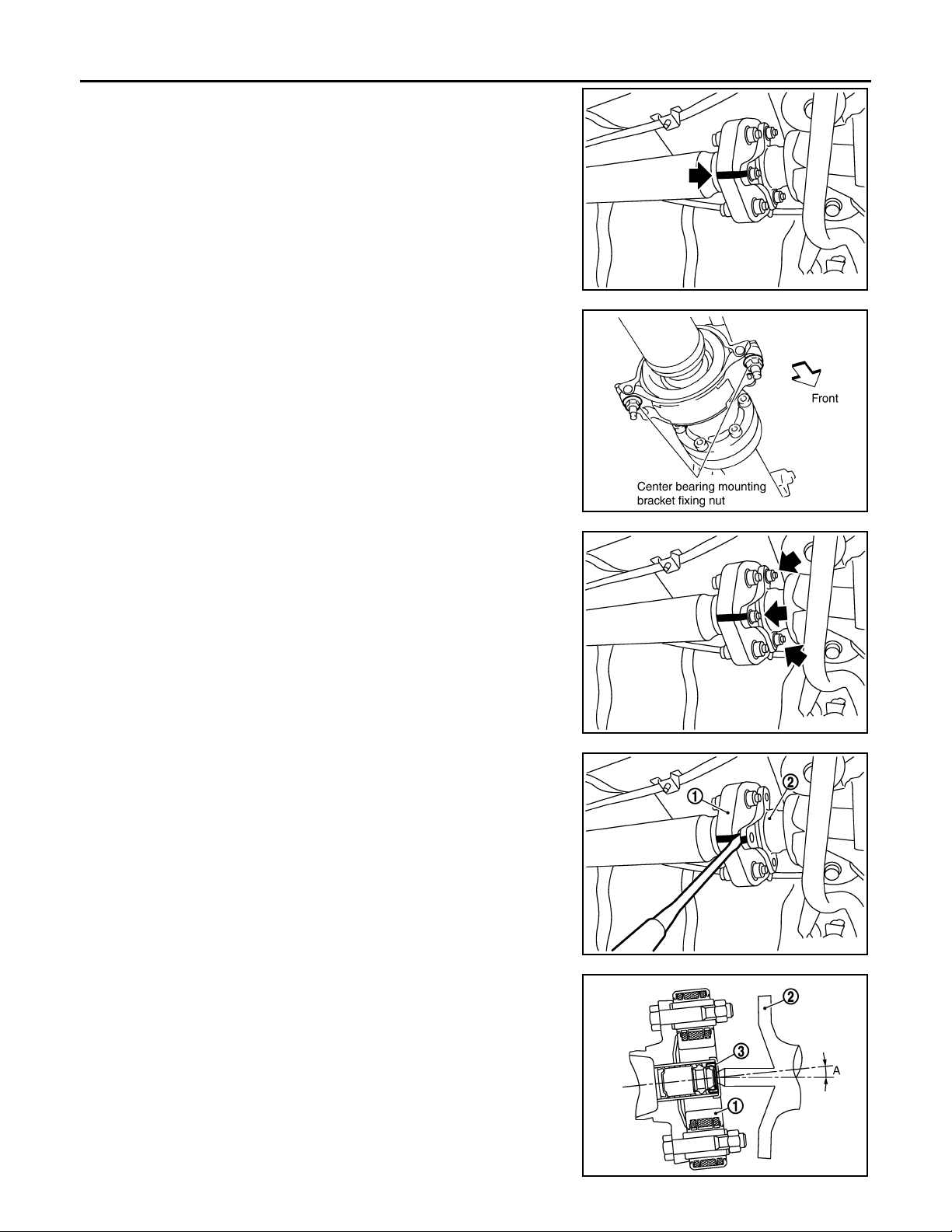
REAR PROPELLER SHAFT
Revision: October 2006
2007 G35 Sedan
< ON-VEHICLE REPAIR >
5. Put matching marks on propeller shaft rubber coupling with final
drive companion flange.
CAUTION:
For matching marks, use paint. Never damage propeller
shaft rubber coupling and final drive companion flange.
6. Loosen mounting nuts of center bearing mounting brackets.
CAUTION:
Tighten mounting nuts temporarily.
[REAR PROPELLER SHAFT: 3S80A-R]
JSDIA0009ZZ
7. Remove propeller shaft assembly fixing bolts and nuts.
CAUTION:
Never remove the rubber coupling from the propeller shaft
assembly.
8. Slightly separate the rubber coupling (1) from the final drive
companion flange (2).
CAUTION:
Never damage the final drive companion flange and rubber
coupling.
PDIA0402E
JSDIA0010ZZ
JSDIA0128ZZ
9. Remove center bearing mounting bracket fixing nuts.
CAUTION:
• The angle (A), which the third axis rubber coupling (1)
forms with the final drive companion flange (2), must be 5°
or less.
• Never damage the grease seal (3).
• Never damage the rubber coupling.
10. Slide the propeller shaft forward the vehicle slightly. Separate
the propeller shaft from the final drive companion flange.
CAUTION:
JSDIA0137ZZ
DLN-94
Page 95
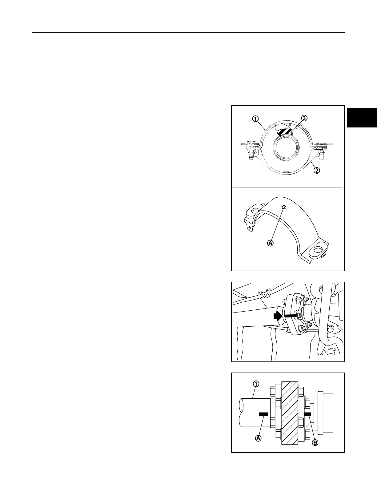
REAR PROPELLER SHAFT
Revision: October 2006
2007 G35 Sedan
< ON-VEHICLE REPAIR >
• The angle, which the third axis rubber coupling forms with the final drive companion flange,
must be 5° or less.
• Never damage the grease seal.
• Never damage the rubber coupling.
11. Remove the propeller shaft assembly from the vehicle.
CAUTION:
Never damage the rear oil seal of transmission.
[REAR PROPELLER SHAFT: 3S80A-R]
A
B
INSTALLATION
Note the following, and install in the reverse order of removal.
• Install center bearing mounting bracket (Upper) (1) with its arrow
mark (A) facing forward.
• Adjust position of center bearing mounting bracket (1, 2) sliding
back and forth to prevent play in thrust direction of center bearing
insulator (3). Install bracket to vehicle.
JSDIA0130ZZ
C
DLN
E
F
G
H
I
J
• Align matching marks to install propeller shaft rubber coupling to
final drive companion flange.
• After assembly, perform a driving test to check propeller shaft
vibration. If vibration occurred, separate propeller shaft from final
drive. Reinstall companion flange after rotating it by 120, 240
degrees. Then perform driving test and check propeller shaft vibration again at each point.
• If propeller shaft or final drive has been replaced, connect them as
follows:
- Install the propeller shaft (1) while aligning its matching mark (A)
with the matching mark (B) on the joint as close as possible.
JSDIA0009ZZ
JSDIA0077ZZ
K
L
M
N
O
P
CAUTION:
DLN-95
Page 96
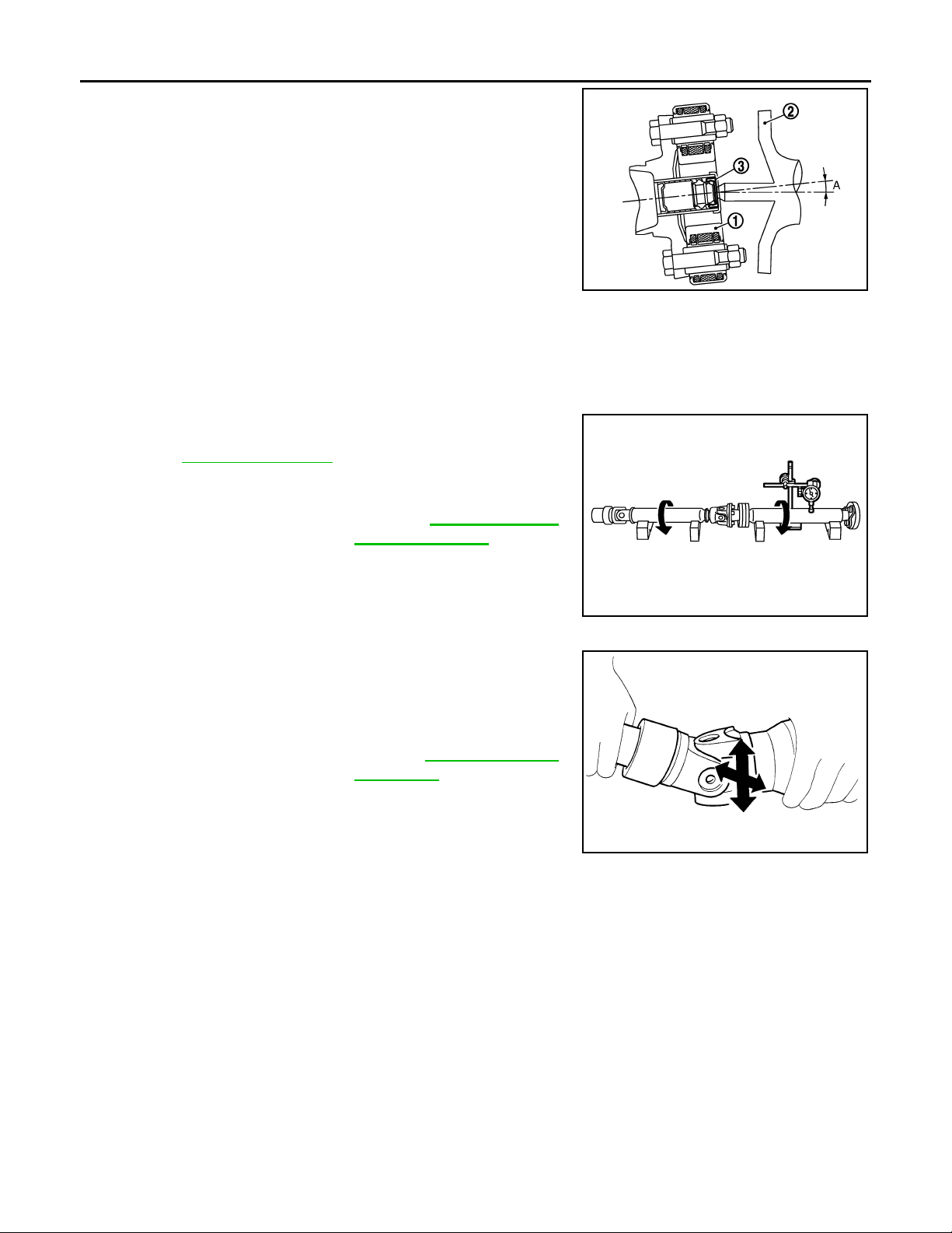
REAR PROPELLER SHAFT
Revision: October 2006
2007 G35 Sedan
< ON-VEHICLE REPAIR >
• The angle (A), which the third axis rubber coupling (1) forms
with the final drive companion flange (2), must be 5° or less.
• Never damage the grease seal (3).
• Never damage the rubber coupling.
• Never damage the rear oil seal of transmission.
• Avoid damaging the rubber coupling, protect it with a shop
towel or equivalent.
[REAR PROPELLER SHAFT: 3S80A-R]
JSDIA0137ZZ
Inspection INFOID:0000000000957327
APPEARANCE
Check propeller shaft for bend and damage. If damage is detected, replace propeller shaft assembly.
PROPELLER SHAFT RUNOUT
Check propeller shaft runout at measuring points. If runout exceeds
specifications, replace propeller shaft assembly. For measuring
point, refer to DLN-92, "
Limit
Propeller shaft runout : Refer to DLN-97, "
Inspection"
Propel-
ler Shaft Runout".
JSDIA0078ZZ
JOURNAL AXIAL PLAY
As shown in the figure, while fixing yoke on one side, check axial
play of joint. If outside the standard, replace propeller shaft assembly.
Standard
Journal axial play : Refer to DLN-97, "
Journal
Axial Play".
CAUTION:
Never disassemble joints.
SPD874
CENTER BEARING
Check center bearing for noise and damage. If noise or damage is detected, replace propeller shaft assembly.
CAUTION:
Never disassemble center bearing.
DLN-96
Page 97
SERVICE DATA AND SPECIFICATIONS (SDS)
Revision: October 2006
2007 G35 Sedan
< SERVICE DATA AND SPECIFICATIONS (SDS)
[REAR PROPELLER SHAFT: 3S80A-R]
SERVICE DATA AND SPECIFICATIONS (SDS)
SERVICE DATA AND SPECIFICATIONS (SDS)
General Specifi cati ons INFOID:0000000000957328
2WD
Applied model
Propeller shaft model 3S80A-R
Number of joints 3
1st joint Shell type
Type of jo urnal bearings
(Non-disassembly type)
Coupling method with transmission Sleeve type
Coupling method with rear final drive Rubber coupling type
Shaft length
Shaft outer diameter
2nd joint Shell type
3rd joint Rubber coupling type
1st (Spider to spider) 724 mm (28.50 in)
2nd (Spider to rubber coupling center) 769 mm (30.28 in)
1st 82.6 mm (3.25 in)
2nd 75.0 mm (2.95 in)
Propeller Shaft Runout INFOID:0000000000957329
VQ35HR
A/T
A
B
C
DLN
E
F
G
H
Unit: mm (in)
Item Limit
Propeller shaft runout 0.8 (0.031)
Journal Axial Play INFOID:0000000000957330
Unit: mm (in)
Item Standard
Journal axial play 0 (0)
I
J
K
L
M
N
O
P
DLN-97
Page 98
NOISE, VIBRATION AND HARSHNESS (NVH) TROUBLESHOOTING
Revision: October 2006
2007 G35 Sedan
< SYMPTOM DIAGNOSIS >
[REAR PROPELLER SHAFT: 3F80A-1VL107]
SYMPTOM DIAGNOSIS
NOISE, VIBRATION AND HARSHNESS (NVH) TROUBLESHOOTING
NVH Troubleshooting Chart INFOID:0000000000957331
Use the chart below to help you find the cause of the symptom. If necessary, repair or replace these parts.
Reference
Possible cause and SUSPECTED PARTS
—
DLN-100, "Inspection"
DLN-104, "Inspection"
Inspection"
DLN-104, "
—
Inspection"
DLN-104, "
DLN-104, "Inspection"
NVH in DLN section.
NVH in FAX, RAX, FSU and RSU section.
NVH in WT section.
NVH in WT section.
NVH in RAX section.
NVH in BR section.
NVH in ST section.
Symptom
×: Applicable
Uneven rotating torque
Center bearing improper installation
Excessive center bearing axial end play
Center bearing mounting (insulator) cr acks, damage or deterioration
Excessive joint angle
Rotation imbalance
Excessive runout
DIFFERENTIAL
AXLE AND SUSPENSION
TIRES
ROAD WHEEL
DRIVE SHAFT
BRAKES
STEERING
Noise ЧЧЧЧЧЧЧЧЧЧЧЧЧЧ
Shake × × ЧЧЧЧЧЧ
Vibration ЧЧЧЧЧЧЧ ×× × ×
DLN-98
Page 99
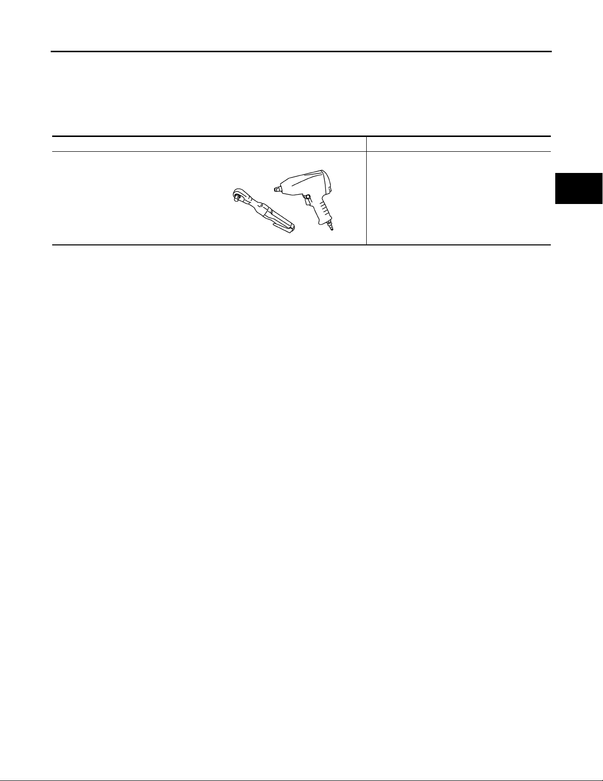
< PREPARATION >
Revision: October 2006
2007 G35 Sedan
PREPARATION
[REAR PROPELLER SHAFT: 3F80A-1VL107]
PREPARATION
PREPARATION
Commercial Service Tools INFOID:0000000000957332
Tool name Description
Power tool Loosening bolts and nuts
PBIC0190E
A
B
C
DLN
E
F
G
H
K
M
N
O
P
I
J
L
DLN-99
Page 100
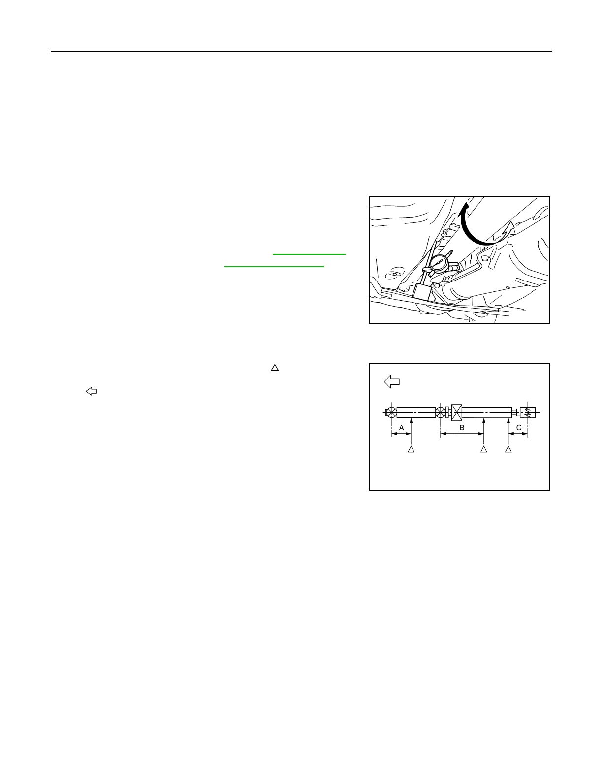
REAR PROPELLER SHAFT
Revision: October 2006
2007 G35 Sedan
< ON-VEHICLE MAINTENANCE >
[REAR PROPELLER SHAFT: 3F80A-1VL107]
ON-VEHICLE MAINTENANCE
REAR PROPELLER SHAFT
Inspection INFOID:0000000000957333
NOISE
• Check the propeller shaft tube surface for dents or cracks. If damaged, replace propeller shaft assembly.
• If center bearing is noisy or damaged, replace propeller shaft assembly.
VIBRATION
• If vibration is present at high speed, inspect propeller shaft runout first.
1. Measure propeller shaft runout at several points by rotating final
drive companion flange with hands.
Limit
Propeller shaft runout : Refer to DLN-105, "
peller Shaft Runout".
2. If runout still exceeds specifications, separate propeller shaft at
final drive companion flange; then rotate companion flange 60,
120 180, 240, 300 degrees and install propeller shaft.
3. Check runout again. If runout still exceeds specifications,
replace propeller shaft assembly.
4. Check the vibration by driving vehicle.
Pro-
SDIA1087E
RUNOUT MEASURING POINT
• Propeller shaft runout measuring point (Point “ ”).
: Vehicle front
Dimension A: 162 mm (6.38 in)
B: 245 mm (9.65 in)
C: 185 mm (7.28 in)
PDIA0772J
DLN-100
 Loading...