

Page 1

BODY EXTERIOR, DOORS, ROOF & VEHICLE SECURITY
Revision: October 2006
2007 G35 Sedan
SECTION DLK
A
B
CONTENTS
INTELLIGENT KEY SYSTEM
BASIC INSPECTION ....................................
DIAGNOSIS AND REPAIR WORKFLOW ..........6
Work Flow .................................................................6
INSPECTION AND ADJUSTMENT ..................... 9
ADDITIONAL SERVICE WHEN REPLACING
CONTROL UNIT ..........................................................
ADDITIONAL SERVICE WHEN REPLACING
CONTROL UNIT : Description ..................................
ADDITIONAL SERVICE WHEN REPLACING
CONTROL UNIT : Special Repair Requirement .......
FUNCTION DIAGNOSIS ..............................10
DOOR LOCK FUNCTION ..................................10
DOOR LOCK AND UNLOCK SWITCH .....................10
DOOR LOCK AND UNLOCK SWITCH : System
Diagram ........................... ................ ............. ...........
DOOR LOCK AND UNLOCK SWITCH : System
Description ..............................................................
DOOR LOCK AND UNLOCK SWITCH :
Component Parts Location ....................................
DOOR LOCK AND UNLOCK SWITCH :
Component Description ......................... .................
DOOR REQUEST SWITCH ...................... ... ... .... .......13
DOOR REQUEST SWITCH : System Diagram ......13
DOOR REQUEST SWITCH : System Description ....13
DOOR REQUEST SWITCH :
Component Parts Location ....................................
DOOR REQUEST SWITCH :
Component Description ......................... .................
INTELLIGENT KEY ...................................................18
INTELLIGENT KEY : System Diagram ...................18
INTELLIGENT KEY : System Description ...............18
INTELLIGENT KEY : Component Parts Location ....20
INTELLIGENT KEY : Component Description .......23
10
10
10
13
15
18
DOOR & LOCK
TRUNK OPEN FUNCTION ...............................24
TRUNK LID OPENER SWITCH .................................24
6
9
9
9
TRUNK LID OPENER SWITCH : System Diagram
TRUNK LID OPENER SWITCH : System Descrip-
tion ................................ ................................... ........
TRUNK LID OPENER SWITCH :
Component Parts Location ....................................
TRUNK LID OPENER SWITCH :
Component Description ..........................................
TRUNK REQUEST SWITCH .....................................27
TRUNK REQUEST SWITCH : System Diagram .....27
TRUNK REQUEST SWITCH : System Descrip-
tion ................................ ................................... ........
TRUNK REQUEST SWITCH :
Component Parts Location ....................................
TRUNK REQUEST SWITCH :
Component Description ..........................................
INTELLIGENT KEY ....................................................32
INTELLIGENT KEY : System Diagram ....................32
INTELLIGENT KEY : System Description ...............32
INTELLIGENT KEY : Component Parts Location ....33
INTELLIGENT KEY : Component Description ........36
WARNING FUNCTION ......................................37
System Description ..................................................37
Component Parts Location ....................................41
KEY REMINDER FUNCTION ............................45
System Description ..................................................45
Component Parts Location ....................................45
INTEGRATED HOMELINK TRANSMITTER ....49
Component Description ...........................................49
DIAGNOSIS SYSTEM (BCM) ...........................50
COMMON ITEM .........................................................50
COMMON ITEM : CONSULT-III Function (BCM -
COMMON ITEM) .....................................................
....
24
24
24
27
27
29
32
50
C
D
E
F
G
H
I
J
DLK
L
M
N
O
P
DLK-1
Page 2

DOOR LOCK ............................................................. 50
Revision: October 2006
2007 G35 Sedan
DOOR LOCK : CONSULT-III Function (BCM -
DOOR LOCK) .........................................................
INTELLIGENT KEY ................................................... 51
INTELLIGENT KEY : CONSULT-III Function
(BCM - INTELLIGENT KEY) ...................................
TRUNK ...................................................................... 54
TRUNK : CONSULT-III Function (BCM - TRUNK) ... 54
50
51
COMPONENT DIAGNOSIS ........................ 56
U1000 CAN COMM CIRCUIT ............................56
Description ....................... .......................... ............. 56
DTC Logic ............................................................... 56
Diagnosis Procedure .............................................. 56
U1010 CONTROL UNIT (CAN) ......................... 57
DTC Logic ............................................................... 57
Diagnosis Procedure .............................................. 57
Special Repair Requirement ................................... 57
B2621 INSIDE KEY ANTENNA 1 ...................... 58
Description ....................... .......................... ............. 58
DTC Logic ............................................................... 58
Diagnosis Procedure .............................................. 58
B2622 INSIDE KEY ANTENNA 2 ...................... 60
Description ....................... .......................... ............. 60
DTC Logic ............................................................... 60
Diagnosis Procedure .............................................. 60
B2623 INSIDE KEY ANTENNA 3 ...................... 62
Description ....................... .......................... ............. 62
DTC Logic ............................................................... 62
Diagnosis Procedure .............................................. 62
KEY SLOT ......................................................... 72
Description ..............................................................72
Component Fu nction Check ..... .............................72
Diagnosis Procedure ..... ... .......................................72
Component Inspection ............................................73
KEY CYLINDER SWITCH ................................. 74
Description ..............................................................74
Component Function Check ................................... 74
Diagnosis Procedure ..... ... .......................................74
Component Inspection ............................................75
Special Repair Requirement ............................ ... .... 75
UNLOCK SENSOR ............................................ 77
Description ..............................................................77
Component Fu nction Check ..... .............................77
Diagnosis Procedure ..... ... .......................................77
Component Inspection ............................................78
TRUNK LID OPENER SWITCH ........................ 80
Description ..............................................................80
Component Fu nction Check ..... .............................80
Diagnosis Procedure ..... ... .......................................80
Component Inspection ............................................81
TRUNK LID OPENER CANCEL SWITCH ........ 82
Description ..............................................................82
Component Fu nction Check ..... .............................82
Diagnosis Procedure ..... ... .......................................82
Component Inspection ............................................83
TRUNK ROOM LAMP SWITCH ........................ 84
Description ..............................................................84
Component Fu nction Check ..... .............................84
Diagnosis Procedure ..... ... .......................................84
Component Inspection ............................................85
POWER SUPPLY AND GROUND CIRCUIT ..... 64
Diagnosis Procedure .............................................. 64
DOOR SWITCH ................................................. 65
Description ....................... .......................... ............. 65
Component Function Check ................................. 65
Diagnosis Procedure .............................................. 65
Component Inspection ............................................ 67
DOOR LOCK AND UNLOCK SWITCH ............. 68
DRIVER SIDE ...................................................... ...... 68
DRIVER SIDE : Description .................................... 68
DRIVER SIDE : Component Function Check ........ 68
DRIVER SIDE : Diagnosis Procedure .................... 68
DRIVER SIDE : Special Repair Requirement ......... 69
PASSENGER SIDE ................................................... 69
PASSENGER SIDE : Description ........................... 69
PASSENGER SIDE :
Component Function Check .................................
PASSENGER SIDE : Diagnosis Procedure ........... 70
PASSENGER SIDE : Special Repair Requirement
69
...
71
DLK-2
DOOR REQUEST SWITCH ............................... 87
Description ..............................................................87
Component Fu nction Check ..... .............................87
Diagnosis Procedure ..... ... .......................................87
Component Inspection ............................................89
TRUNK OPENER REQUEST SWITCH ............. 90
Description ..............................................................90
Component Fu nction Check ..... .............................90
Diagnosis Procedure ..... ... .......................................90
Component Inspection ............................................91
DOOR LOCK ACTUATOR ................................ 92
DRIVER SIDE ............................................................92
DRIVER SIDE : Description .................................... 92
DRIVER SIDE : Component Function Check ........92
DRIVER SIDE : Diagnosis Procedure .....................92
PASSENGER SIDE ................................................... 92
PASSENGER SIDE : Description ...........................93
PASSENGER SIDE :
Component Fu nction Check ..... .............................
PASSENGER SIDE : Diagnosis Procedure ............ 93
93
Page 3

REAR LH ........ ... ... .... ... ..............................................
Revision: October 2006
2007 G35 Sedan
REAR LH : Description ............................................93
REAR LH : Component Function Check ...............94
REAR LH : Diagnosis Procedure ............................94
REAR RH .............................. .... .................................94
REAR RH : Description ...........................................94
REAR RH : Component Function Check ...............94
REAR RH : Diagnosis Procedure ............................95
93
TRUNK LID OPENER ACTUATOR ...................96
Description ..............................................................96
Component Function Check ..................................96
Diagnosis Procedure ........................... ... ... ... .... .......96
FUEL LID OPENER ACTUATOR ......................98
Description ..............................................................98
Component Function Check ..................................98
Diagnosis Procedure ........................... ... ... ... .... .......98
INTELLIGENT KEY WARNING BUZZER ..........99
Description ..............................................................99
Component Function Check ..................................99
Diagnosis Procedure ........................... ... ... ... .... .......99
Component Inspection ..........................................100
OUTSIDE KEY ANTENNA ...............................101
Description ............................................................101
Component Function Check ................................101
Diagnosis Procedure ........................... ... ... ... .... .....101
REMOTE KEYLESS ENTRY RECEIVER ........104
Description ............................................................104
Component Function Check ................................104
Diagnosis Procedure ........................... ... ... ... .... .....104
INTELLIGENT KEY ..........................................107
Description ............................................................107
Component Function Check ................................107
Diagnosis Procedure ........................... ... ... ... .... .....107
Component Inspection ..........................................107
Special Repair Requirement .................................108
Component Function Check ................................114
Diagnosis Procedure .............................................114
HAZARD FUNCTION ...................................... 115
Description .......................... ... ....... ...... ....... ...... ......115
Component Function Check ................................115
Diagnosis Procedure .............................................115
INTEGRATED HOMELINK TRANSMITTER ..116
Description .......................... ... ....... ...... ....... ...... ......116
Component Function Check ................................116
Diagnosis Procedure .............................................116
INTEGRATED HOMELINK TRANSMITTER
SYSTEM ..........................................................
Wiring Diagram (BCM - INTEGRATED
HOMELINK TRANSMITTER SYSTEM) ................
118
118
ECU DIAGNOSIS ....................................... 120
BCM (BODY CONTROL MODULE) ...............120
Reference Value ....................................................120
Wiring Diagram — POWER DOOR LOCK SYS-
TEM — ..................................................................
Wiring Diagram — INTELLIGENT KEY SYSTEM
— ..................................... ......................................
Wiring Diagram — TRUNK LID OPENER SYS-
TEM — ..................................................................
Fail Safe .......... ...... ....... ...... ....... ...... ...... ....... ...... ...161
DTC Inspection Priority Chart .............................163
DTC Index ....... ...... ....... ...... ....... ... ...... ....... ...... ......164
143
148
158
SYMPTOM DIAGNOSIS ............................ 167
INTELLIGENT KEY SYSTEM SYMPTOMS ... 167
Symptom Table .....................................................167
DOOR LOCK FUNCTION SYMPTOMS .......... 168
DOOR LOCK AND UNLOCK SWITCH ...................168
DOOR LOCK AND UNLOCK SWITCH : Symptom
Table ................................... ....... ... ...... ....... ...... ......
168
A
B
C
D
E
F
G
H
I
J
DLK
L
KEY SLOT ILLUMINATION .............................109
Description ............................................................109
Component Function Check ................................109
Diagnosis Procedure ........................... ... ... ... .... .....109
HORN FUNCTION ............................................111
Description ............................................................111
Component Function Check ................................111
Diagnosis Procedure ............................................111
COMBINATION METER DISPLAY FUNC-
TION .................................................................
Description ............................................................113
Component Function Check ................................113
Diagnosis Procedure ........................... ... ... ... .... .....113
WARNING CHIME FUNCTION ........................114
Description ............................................................114
113
DLK-3
DOOR REQUEST SWITCH .....................................168
DOOR REQUEST SWITCH : Symptom Table ......168
INTELLIGENT KEY ..................................................169
INTELLIGENT KEY : Symptom Table ...................169
TRUNK OPEN FUNCTION SYMPTOMS ........171
TRUNK LID OPENER SWITCH ...............................171
TRUNK LID OPENER SWITCH : Symptom Table ..171
TRUNK REQUEST SWITCH ...................................171
TRUNK REQUEST SWITCH : Symptom Table ....171
INTELLIGENT KEY ..................................................171
INTELLIGENT KEY : Symptom Table ...................171
WARNING FUNCTION SYMPTOMS .............. 173
Symptom Table .....................................................173
M
N
O
P
Page 4

KEY REMINDER FUNCTION SYMPTOMS ..... 176
Revision: October 2006
2007 G35 Sedan
Symptom Table .................. .... ... ............................176
HAZARD AND BUZZER REMINDER FUNC-
TION SYMPTOMS ...........................................
Symptom Table .................. .... ... ............................177
177
DOOR ...............................................................200
FRONT DOOR ......................................................... 200
FRONT DOOR : Exploded View ........................... 200
FRONT DOOR : Removal and Installation ........... 201
FRONT DOOR : Adjustment ................................. 202
HAZARD AND HORN REMINDER FUNC-
TION SYMPTOMS ...........................................
Symptom Table .................. .... ... ............................178
178
SQUEAK AND RATTLE TROUBLE DIAG-
NOSES .............................................................
Work Flow ........ ... .... ...............................................179
Inspection Procedure ............................................. 181
Diagnostic Worksheet ............................................183
179
PRECAUTION ............................................185
PRECAUTIONS ............................................... 185
Precaution for Supplemental Restraint System
(SRS) "AIR BAG" and "SEAT BELT PRE-TEN-
SIONER" ............................. ................. ..................
Precaution for Procedure without Cowl Top Cover ..185
Precaution Necessary for Steering Wheel Rota-
tion after Battery Disconnect .................................
Work ......................................................................186
185
185
PREPARATION ..........................................187
PREPARATION ............................................... 187
Special Service Tools ............................................187
Commercial Service Tools .....................................187
ON-VEHICLE MAINTENANCE ..................188
PRE-INSPECTION FOR DIAGNOSTIC ........... 188
Basic Inspection ....................................................188
ON-VEHICLE REPAIR ...............................190
REAR DOOR ................................... ... ... ... ............... 203
REAR DOOR : Exploded View .............................203
REAR DOOR : Removal and Installation .............. 204
REAR DOOR : Adjustment ................................... 205
DOOR LOCK ....................................................207
FRONT DOOR LOCK .............................................. 207
FRONT DOOR LOCK : Exploded View ................ 207
FRONT DOOR LOCK : Removal and Installation .207
REAR DOOR LOCK ..................... ... ... ... ... .... ... ........ 209
REAR DOOR LOCK : Exploded View ................... 209
REAR DOOR LOCK : Removal and Installation ... 210
TRUNK LID .......................................................213
TRUNK LID ASSEMBLY ......................................... 213
TRUNK LID ASSEMBLY : Exploded View ............ 213
TRUNK LID ASSEMBLY : Removal and Installa-
tion ........................................................................
TRUNK LID ASSEMBLY : Adjustment .................. 215
TRUNK LID LOCK ............................. ... ... .... ... ... ..... 215
TRUNK LID LOCK : Exploded View ..................... 215
TRUNK LID LOCK : Removal and Installation ...... 216
TRUNK LID WEATHERSTRIP ........................... ... .. 216
TRUNK LID WEATHERSTRIP : Exploded View ... 216
TRUNK LID WEATHERSTRIP : Removal and In-
stallation ........................... .....................................
214
217
DOOR SWITCH ................................................218
Removal and Installation ....................................... 218
HOOD ............................................................... 190
HOOD ASSEMBLY ..................................................190
HOOD ASSEMBLY : Exploded View ..................... 190
HOOD ASSEMBLY : Removal and Installation .....191
HOOD ASSEMBLY : Adjustment ..........................192
HOOD LOCK CONTROL ......................................... 192
HOOD LOCK CONTROL : Exploded View ............192
HOOD LOCK CONTROL : Removal and Installa-
tion ................................... ......................................
HOOD LOCK CONTROL : Inspection ................... 195
RADIATOR CORE SUPPORT ......................... 196
Exploded View ........................... ... .........................196
Removal and Installation .......................................196
FRONT FENDER ............................................. 199
Exploded View ........................... ... .........................199
Removal and Installation .......................................199
193
DLK-4
INSIDE KEY ANTENNA ...................................219
INSTRUMENT CENTER .. ... ... ... .... ... ... ... ... .... ... ... ..... 219
INSTRUMENT CENTER : Exploded View ............ 219
INSTRUMENT CENTER : Removal and Installa-
tion ........................................................................
CONSOLE ............................................................... 219
CONSOLE : Exploded View .................................. 219
CONSOLE : Removal and Installation .................. 219
TRUNK ROOM ...... ... ............................................... 219
TRUNK ROOM : Exploded View ........................... 219
TRUNK ROOM : Removal and Installation ........... 219
219
OUTSIDE KEY ANTENNA ...............................221
DRIVER SIDE .......................................................... 221
DRIVER SIDE : Exploded View ............................ 221
DRIVER SIDE : Removal and Installation ............. 221
PASSENGER SIDE ................................................. 221
Page 5

PASSENGER SIDE : Exploded View ....................
Revision: October 2006
2007 G35 Sedan
PASSENGER SIDE : Removal and Installation ....221
REAR BUMPER ......................................................221
REAR BUMPER : Exploded View .........................221
REAR BUMPER : Removal and Installation .........221
221
INTELLIGENT KEY WARNING BUZZER ........222
Exploded View ......................................................222
Removal and Installation ....................................... 222
KEY SLOT ........................................................223
Exploded View ......................................................223
Removal and Installation ....................................... 223
TRUNK OPENER REQUEST SWITCH ..........224
Exploded View .......................................................224
Removal and Installation .......................................224
TRUNK LID OPENER SWITCH ...................... 225
Exploded View .......................................................225
Removal and Installation .......................................225
TRUNK LID OPENER CANCEL SWITCH ...... 226
Exploded View .......................................................226
Removal and Installation .......................................226
REMOTE KEYLESS ENTRY RECEIVER ....... 227
Exploded View .......................................................227
Removal and Installation .......................................227
A
B
C
D
E
F
G
H
I
J
DLK
L
M
N
O
P
DLK-5
Page 6
DIAGNOSIS AND REPAIR WORKFLOW
B
Revision: October 2006
2007 G35 Sedan
< BASIC INSPECTION >
[INTELLIGENT KEY SYSTEM]
BASIC INSPECTION
DIAGNOSIS AND REPAIR WORKFLOW
Work Flow INFOID:0000000000961084
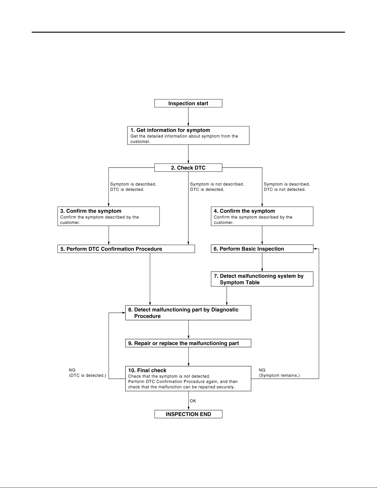
OVERALL SEQUENCE
DETAILED FLOW
JMKIA0101G
DLK-6
Page 7

< BASIC INSPECTION >
Revision: October 2006
2007 G35 Sedan
DIAGNOSIS AND REPAIR WORKFLOW
[INTELLIGENT KEY SYSTEM]
1.GET INFORMATION FOR SYMPTOM
Get the detailed information from the customer about the symptom (the condition and the environment when
the incident/malfunction occurred).
>> GO TO 2.
2.CHECK DTC
1. Check DTC.
2. Perform the following procedure if DTC is displayed.
- Record DTC and freeze frame data (Print them out with CONSULT-III.)
- Erase DTC.
- Study the relationship between the cause detected by DTC and the symptom described by the customer.
3. Check related service bulletins for information.
Is any symptom described and any DTC detected?
Symptom is described, DTC is displayed>>GO TO 3.
Symptom is described, DTC is not displayed>>GO TO 4.
Symptom is not described, DTC is displayed>>GO TO 5.
3.CONFIRM THE SYMPTOM
Confirm the symptom described by the customer.
Connect CONSULT-III to the vehicle in “DATA MONITOR” mode and check real time diagnosis results.
Verify relation between the symptom and the condition when the symptom is detected.
>> GO TO 5.
4.CONFIRM THE SYMPTOM
A
B
C
D
E
F
G
H
Confirm the symptom described by the customer.
Connect CONSULT-III to the vehicle in “DATA MONITOR ” mode and check real time diagnosis results.
Verify relation between the symptom and the condition when the symptom is detected.
>> GO TO 6.
5.PERFORM DTC CONFIRMATION PROCEDURE
Perform DTC Confirmation Procedure for the displayed DTC, and then check that DTC is detected again.
At this time, always connect CONSULT-III to the vehicle, and check diagnostic results in real time.
If two or more DTCs are detected, refer to DLK-163, "
diagnosis order.
NOTE:
• Freeze frame data is useful if the DTC is not detected.
• Perform Component Function Check if DTC Confirmation Procedure is not included in Service Manual. This
simplified check procedure is an effective alternative though DTC cannot be detected during this check.
If the result of Component Function Check is NG, it is the same as the detection of DTC by DTC Confirmation Procedure.
Is DTC detected?
YES >> GO TO 8.
NO >> Refer to GI-39, "
Intermittent Incident".
DTC Inspection Priority Chart" and determine trouble
6.PERFORM BASIC INSPECTION
Perform DLK-188, "
Inspection End>>GO TO 7.
Basic Inspection".
7.DETECT MALFUNCTIONING SYSTEM BY SYMPTOM TABLE
I
J
DLK
L
M
N
O
P
Detect malfunctioning system according to DLK-167, "
step 4, and determine the trouble diagnosis order based on possible causes and symptom.
>> GO TO 8.
Symptom Table" based on the confirmed symptom in
DLK-7
Page 8

DIAGNOSIS AND REPAIR WORKFLOW
Revision: October 2006
2007 G35 Sedan
< BASIC INSPECTION >
[INTELLIGENT KEY SYSTEM]
8.DETECT MALFUNCTIONING PART BY DIAGNOSTIC PROCEDURE
Inspect according to Diagnostic Procedure of the system.
NOTE:
The Diagnostic Procedure described based on open circuit inspection. A short circuit inspection is also
required for the circuit check in the Diagnostic Procedure.
Is malfunctioning part detected?
YES >> GO TO 9.
NO >> Check voltage of related BCM terminals using CONSUL T-III.
9.REPAIR OR REPLACE THE MALFUNCTIONING PART
1. Repair or replace the malfunctioning part.
2. Reconnect parts or connectors disconnected during Diagnostic Procedure again after repair and replacement.
3. Check DTC. If DTC is displayed, erase it.
>> GO TO 10.
10.FINAL CHECK
When DTC was detected in step 2, perform DTC Confirmation Procedure or Component Function Check
again, and then check that the malfunction have been repaired securely.
When symptom was described from the customer, refer to confirmed symptom in step 3 or 4, and check that
the symptom is not detected.
Does the symptom reappear?
YES (DTC is detected)>>GO TO 8.
YES (Symptom remains)>>GO TO 6.
NO >> INSPECTION END
DLK-8
Page 9

< BASIC INSPECTION >
Revision: October 2006
2007 G35 Sedan
INSPECTION AND ADJUSTMENT
[INTELLIGENT KEY SYSTEM]
INSPECTION AND ADJUSTMENT
ADDITIONAL SERVICE WHEN REPLACING CONTROL UNIT
ADDITIONAL SERVICE WHEN REPLACING CONTROL UNIT : Description
INFOID:0000000000961085
Perform the system initialization when replacing BCM, replacing Intelligent Key or registering an additional
Intelligent Key.
ADDITIONAL SERVICE WHEN REPLACING CONTROL UNIT : Special Repair Requirement
Refer to the CONSULT-III operation manual for the initialization procedure.
INFOID:0000000000961086
A
B
C
D
E
F
G
H
I
J
DLK
L
M
N
O
P
DLK-9
Page 10
DOOR LOCK FUNCTION
B
Revision: October 2006
2007 G35 Sedan
< FUNCTION DIAGNOSIS >
[INTELLIGENT KEY SYSTEM]
FUNCTION DIAGNOSIS
DOOR LOCK FUNCTION
DOOR LOCK AND UNLOCK SWITCH
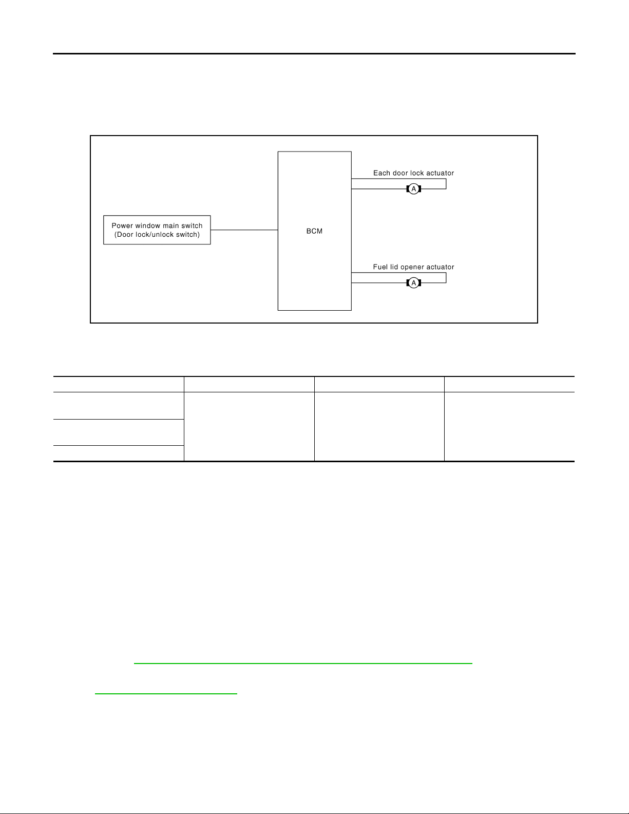
DOOR LOCK AND UNLOCK SWITCH : System Diagram INFOID:0000000000961087
JMKIA0050G
DOOR LOCK AND UNLOCK SWITCH : System Description INFOID:0000000000961088
Switch Input/output signal to BCM BCM function Actuator
Door lock and unlock switch
(Driver side)
Door lock/unlock signal Door lock /unlock control Door lock actuatorDoor lock and unlock switch
(Passenger side)
Door key cylinder switch
DOOR LOCK FUNCTION
Functions Available by Operating the Door Lock and Unlock Switches on Driver Door and Passenger Door
• Interlocked with the locking operation of door lock and unlock switch, door lock actuators of all doors and
fuel lid lock actuator are locked.
• Interlocked with the unlocking operation of door lock and unlock switch, door lock actuators of all doors and
fuel lid lock actuator are unlocked.
Functions Available by Operating the Key Cylinder Switch on Driver Door
• Interlocked with the locking operation of door key cylinder, door lock actuators of all doors and fuel lid lock
actuator are locked.
Selective Unlock Operation
• When door key cylinder is unlocked, door lock actuator driver side and fuel lid lock actuator are unlocked.
• When door key cylinder is unlocked for the second time within 5 seconds after the first operation, door lock
actuators on all doors are unlocked.
Select unlock operation mode can be changed using “DOOR LOCK-UNLOCK SET” mode in “WORK SUPPORT”. Refer to DLK-50, "
DOOR LOCK : CONSULT-III Function (BCM - DOOR LOCK)".
Key Reminder System
Refer to DLK-45, "System Description".
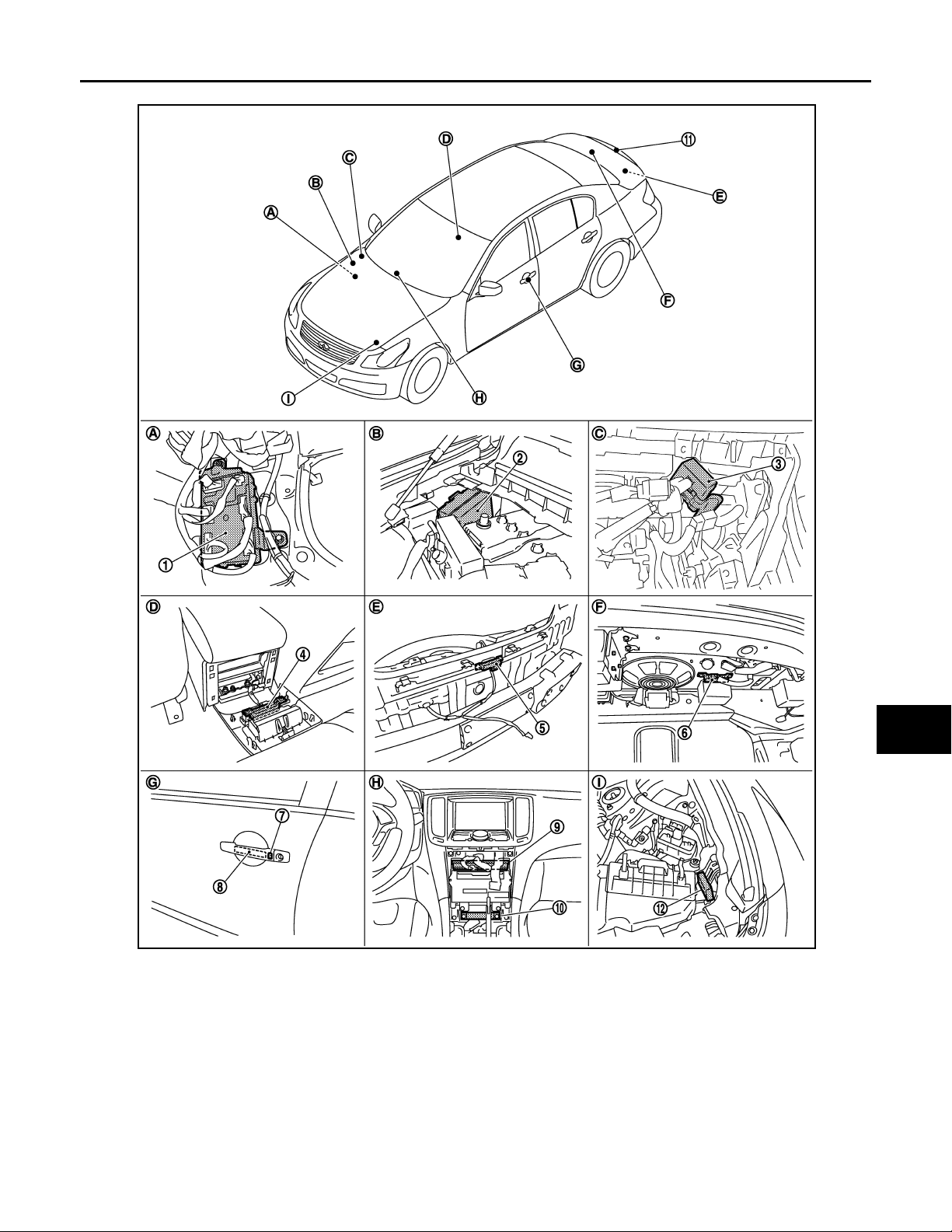
DOOR LOCK AND UNLOCK SWITCH : Component Parts Location INFOID:0000000000961089
DLK-10
Page 11
< FUNCTION DIAGNOSIS >
B
Revision: October 2006
2007 G35 Sedan
DOOR LOCK FUNCTION
[INTELLIGENT KEY SYSTEM]
A
B
C
D
E
F
G
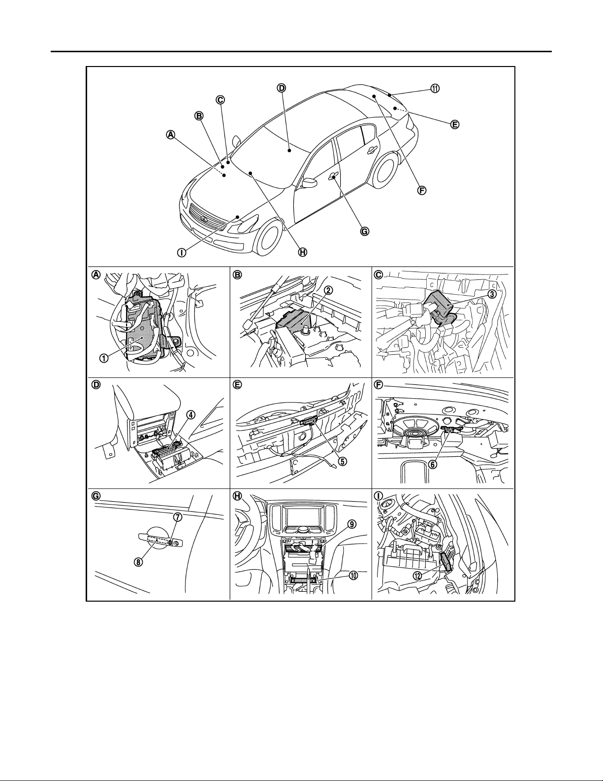
JMKIA0142G
1. BCM
M118,M119,M120,M121,M122,M123
4. Inside key antenna (console) M1 46 5. Outside key antenna (rear bumper)
7. Front outside handle LH (request switch)
D13
10. Inside key antenna (instrument center)
M131
A. Dash side lower (Passenger side). B. Engine room dash panel (RH). C. View with instrument assist lower
2. IPDM E/R E5,E6 3. Remote keyless entry receiver
M104
6. Inside key antenna (trunk room)
B63
8. Front outside handle LH (o utside key
antenna) D14
11. Trunk lid request switch B304 12. Intelligent Key warning buzzer (en-
B49
9. Unified meter and A/C AMP
M66,M67
gine room) E57
panel removed.
H
I
J
DLK
L
M
N
O
P
DLK-11
Page 12
DOOR LOCK FUNCTION
B
Revision: October 2006
2007 G35 Sedan
< FUNCTION DIAGNOSIS >
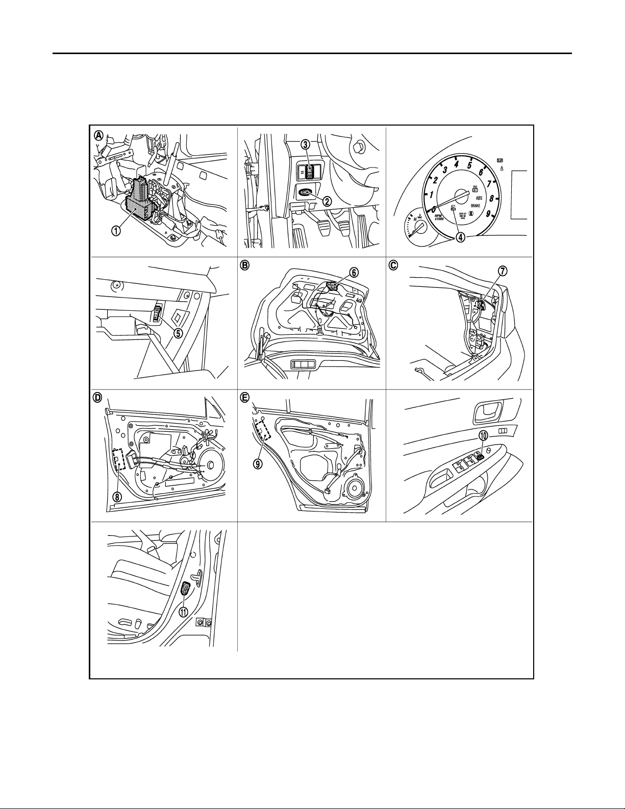
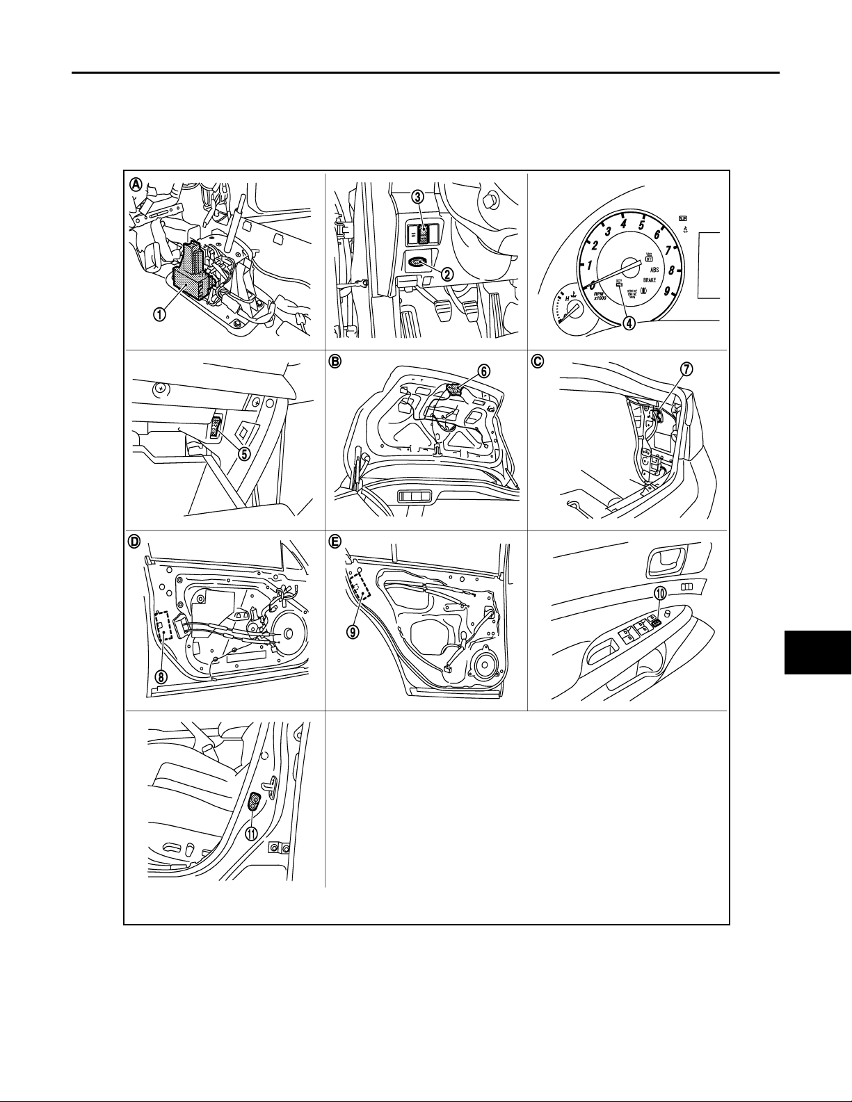
D. View with console rear finisher removed. E. View with rear bumper removed. F. View with trunk rear finisher (up-
G. View of front door LH. H. Behind cluster lid C. I. View with hood seal assembly re-
[INTELLIGENT KEY SYSTEM]
per) removed.
moved.
1. A/T device (detention switch) 2. Key slot M22 3. Trunk lid opener switch M20
4. Combination meter (Key warning lamp)
M53
7. Fuel lid opener actuator B242 8. Front door lock assembly (driver side) D15 9. Rear door lock assembly D55
10. Power window main switch (door lock unlock switch) D8,D9
JMKIA0143G
5. Trunk opener cancel switch M105 6. Trunk lid lock assembly (trunk lid
opener actuator) B303
11. Front door switch B16
DLK-12
Page 13
DOOR LOCK FUNCTION
B
Revision: October 2006
2007 G35 Sedan
< FUNCTION DIAGNOSIS >
A. View with center console assembly re-
moved.
D View with front door finisher removed. E View with rear door finisher removed.
B. View with trunk lid finisher removed. C. View with trunk side finisher re-
[INTELLIGENT KEY SYSTEM]
moved.
A
DOOR LOCK AND UNLOCK SWITCH : Component Description INFOID:0000000000961090
Item Function
BCM Controls the door lock function and room lamp function.
Door lock and unlock switch Transmits lock or unlock signal to BCM.
Door lock actuator Receives lock/unlock signal f rom BCM and locks/unlocks each door.
Door switch Transmits door open/close condition to BCM.
DOOR REQUEST SWITCH
DOOR REQUEST SWITCH : System Diagram INFOID:0000000000961091
B
C
D
E
F
G
H
I
JMKIA0051G
DOOR REQUEST SWITCH : System Description INFOID:0000000000961092
Only when pressing the request switch, it is possible to lock and unlock the door by carrying the Intelligent
Key.
• The Intelligent Key system is a system that makes it possible to lock and unlock the door locks (door lock/
unlock function) by carrying the Intelligent Key, which operates based on the results of electronic ID verification using two-way communications between the Intelligent Key and the vehicle (BCM).
CAUTION:
The driver should always carry the Intelligent Key
• If an action that does not meet the operating conditions of the Intelligent Key system is taken, the buzzer
goes off to inform the driver (Warning chime function).
• When a door lock is locked, unlocked or trunk open with request switch or remote controller button operation, the hazard lamps flash and the Intelligent Key warning buzzer or horn sounds (Hazard and buzzer/horn
reminder function).
• The settings for each function can be changed with the CONSULT-III.
• If an Intelligent Key is lost, a new Intelligent Key can be registered. A maximum of 4 Intelligent Keys can be
registered.
• It is possible to perform a diagnosis on the system and register an Intelligent Key with the CONSULT-III.
OPERATION DESCRIPTION/DOOR LOCK/UNLOCK
• When the BCM detects that each door request switch is pressed, it starts the outside key antenna and inside
key antenna corresponding to the pressed door request switch and transmits the request signal to the Intelligent Key. And then, check that the Intelligent Key is near the door.
• If the Intelligent Key is within the outside key antenna detection area, it receives the request signal and
transmits the key ID signal to the BCM via remote keyless entry receiver.
• BCM receives the key ID signal and compares it with the registered key ID.
J
DLK
L
M
N
O
P
DLK-13
Page 14
DOOR LOCK FUNCTION
B
Revision: October 2006
2007 G35 Sedan
< FUNCTION DIAGNOSIS >
• BCM sends the door lock/unlock signal and sounds Intelligent Key buzzer warning (lock: 2 time, unlock: 1
times) at the same time as a reminder.
OPERATION CONDITION
If the following conditions are not satisfied, door lock/unlock operation is not performed even if the request
switch is operated.
Each request switch operation Operation condition
• All doors are closed
• Ignition switch is in OFF position
Lock operation
Unlock Operation
*: Even with a registered Intelligent Key remaining inside the vehicle, door locks can be unlocked from outside of the vehicle with a spare
Intelligent Key as long as key IDs are different.
• Intelligent Key is out of key slot
• Intelligent Key is outside the vehicle
• Intelligent Key is within outside key antenna detection area
• Intelligent Key is outside the vehicle
• Intelligent Key is within outside key antenna detection area *
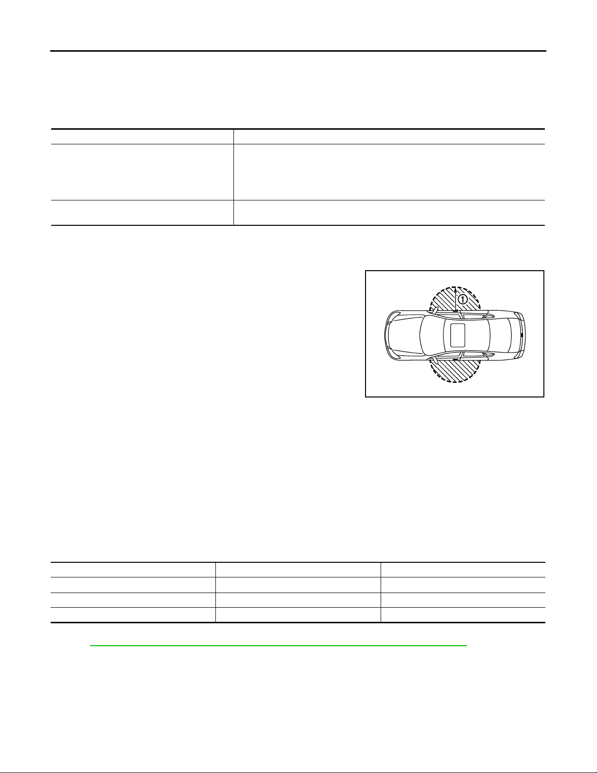
OUTSIDE KEY ANTENNA DETECTION AREA
The outside key antenna detection area of door lock/unlock function
is in the range of approximately 80 cm (31.50 in) surrounding the
driver and passenger door handles (1).
[INTELLIGENT KEY SYSTEM]
JMKIA0103G
SELECTIVE UNLOCK FUNCTION
When an LOCK signal is sent from door request switch (driver side or passenger side), all doors will be locked.
When an UNLOCK signal is sent from door request switch (driver side or passenger side) once, driver's door
will be unlocked.
Then, if an UNLOCK signal is sent from door request switch (driver side and passenger side) again within 5
seconds, all other door will be unlocked.
HAZARD AND BUZZER REMINDER FUNCTION
During lock, unlock, or trunk opening operation by each request switch, the hazard warning lamps and Intelligent Key warning buzzer will blink or honk as a reminder.
When doors are locked, unlocked by each request switch, IPDM E/R honks Intelligent Key warning buzzer as
a reminder and transmits hazard request signal to BCM via CAN communication line.
BCM flashes hazard warning lamps as a reminder.
Operating function of hazard and buzzer reminder
Operation Hazard warning lamp flash Intelligent Key warning buzzer honk
Unlock Once Once
Lock Twice Twice
Trunk open — Fourth times
How to change hazard and buzzer reminder mode
Refer to DLK-51, "
INTELLIGENT KEY : CONSULT-III Function (BCM - INTELLIGENT KEY)".
AUTO DOOR LOCK FUNCTION
When all doors are locked, ignition switch is in OFF position and key switch is OFF (Intelligent Key is not
inserted in key slot), doors are unlocked with door request switch
When BCM does not receive the following signals within 60 seconds, all doors are locked.
• Door switch is ON (door is opened)
• Door is locked
• Ignition switch is ON (ignition switch is pressed)
• Key switch is ON (Intelligent Key is inserted in key slot)
DLK-14
Page 15

DOOR LOCK FUNCTION
Revision: October 2006
2007 G35 Sedan
< FUNCTION DIAGNOSIS >
Auto door lock mode can be changed by “AUTO LOCK SET” mode in “WORK SUPPORT”. Refer to DLK-51,
"INTELLIGENT KEY : CONSULT-III Function (BCM - INTELLIGENT KEY)".
ROOM LAMP OPERATION
When the following conditions are met:
• Condition of interior lamp switch is in DOOR position
• Door switch OFF (all the doors are closed)
Intelligent Key system turns on interior lamp (for 15 seconds) by receiving UNLOCK signal from door request
switch. For detailed description, refer to INL-9, "
System Description".
LIST OF OPERATION RELATED PARTS
Parts marked with × are the parts related to operation.
[INTELLIGENT KEY SYSTEM]
A
B
C
D
E
Door lock function
Intelligent Key
Key slot
Remote keyless entry receiver
Door switch
Door request switch (Driver, Passenger)
Door lock actuator
Inside key antenna
Outside key antenna (Driver, Passenger)
Intelligent Key warning buzzer
CAN communication system
BCM
Hazard warning lamp
Door lock/unlock function by request switch ЧЧЧЧЧЧЧЧ ××
Hazard and buzzer reminder function for door lock/unlock
operation
Key reminder function ЧЧЧЧЧЧЧЧЧЧЧЧ
Selective unlock function by request switch
(Driver side)
Selective unlock function by request switch
(Passenger side)
Auto door lock function ×× ××× ×× ×
× ×××× ××
× ×××× ××
××××
DOOR REQUEST SWITCH : Component Parts Location INFOID:0000000000961093
Push-button ignition switch
DLK
F
G
H
I
J
L
M
N
O
P
DLK-15
Page 16
< FUNCTION DIAGNOSIS >
B
Revision: October 2006
2007 G35 Sedan
DOOR LOCK FUNCTION
[INTELLIGENT KEY SYSTEM]
1. BCM
M118,M119,M120,M121,M122,M123
4. Inside key antenna (console) M146 5. Outside key antenna (rear bumper)
7. Front outside handle LH (request switch)
D13
10. Inside key antenna (instrument center)
M131
A. Dash side lower (Passenger side). B. Engine room dash panel (RH). C. View with instrument assist lower
JMKIA0142G
2. IPDM E/R E5,E6 3. Remote keyless entry receiver
M104
6. Inside key antenna (trunk room)
B63
8. Front outside handle LH (outside key
antenna) D14
11. Trunk lid request switch B304 12. Intelligent Key warning buzzer (en-
B49
9. Unified meter and A/C AMP
M66,M67
gine room) E57
panel removed.
DLK-16
Page 17
DOOR LOCK FUNCTION
B
Revision: October 2006
2007 G35 Sedan
< FUNCTION DIAGNOSIS >
D. View with console rear finisher removed. E. View wit h rear bumper removed. F. View with trunk rear finisher (up-
G. View of front door LH. H. Behind cluster lid C. I. View with hood seal assembly re-
[INTELLIGENT KEY SYSTEM]
per) removed.
moved.
A
B
C
D
E
F
G
H
I
J
DLK
L
M
N
O
1. A/T device (detention switch) 2. Key slot M22 3. Trunk lid opener switch M20
4. Combination meter (Key warning lamp)
M53
7. Fuel lid opener actuator B242 8. Front door lock assembly (driver side) D15 9. Rear door lock assembly D55
10. Power window main switch (door lock unlock switch) D8,D9
JMKIA0143G
P
5. Trunk opener cancel switch M105 6. Trunk lid lock assembly (trunk lid
opener actuator) B303
11. Front door switch B16
DLK-17
Page 18
DOOR LOCK FUNCTION
B
Revision: October 2006
2007 G35 Sedan
< FUNCTION DIAGNOSIS >
A. View with center console assembly re-
moved.
D View with front door finisher removed. E View with rear door finisher removed.
B. View with trunk lid finisher removed. C. View with trunk side finisher re-
[INTELLIGENT KEY SYSTEM]
moved.
DOOR REQUEST SWITCH : Component Description
Item Function
BCM Controls the door lock function and room lamp function.
Door lock and unlock switch Transmits lock or unlock signal to BCM.
Door lock actuator Receives lock/unlock signal from BCM and locks/unlocks each door.
Door switch Transmits door open/close condition to BCM.
Remote keyless entry receiver Receives lock/unlock signal from the Intelligent Key, and then transmits to BCM.
Request switch Transmits lock/unlock operation to BCM.
Intelligent Key Transmits button operation to remote keyless entry receiver.
Outside key antenna Detects if Intelligent Key is outside the vehicle.
Inside key antenna Detects if Intelligent Key is inside the vehicle.
Fuel lid opener actuator Performs lock/unlock of the fuel lid.
Intelligent Key warning buzzer Warns the user of th e lock/unlock condition a nd inappropriate operatio ns with the buzzer soun d.
INFOID:0000000000961094
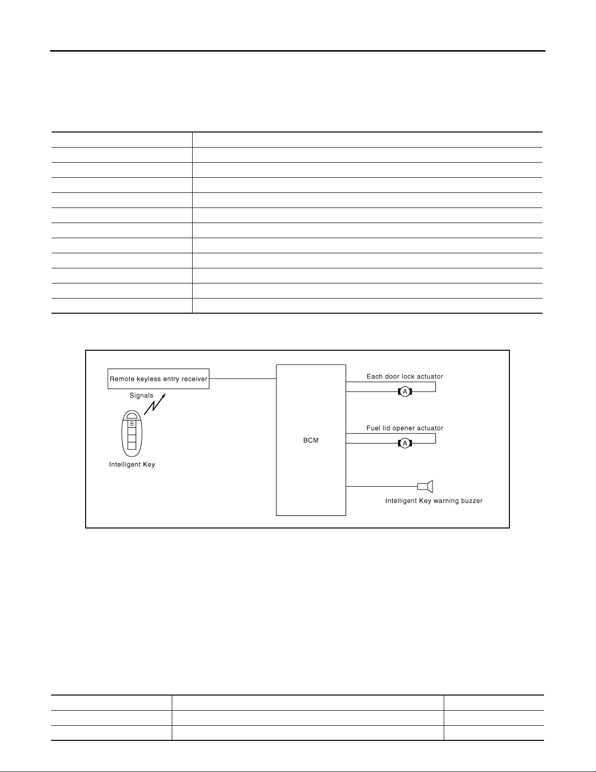
INTELLIGENT KEY
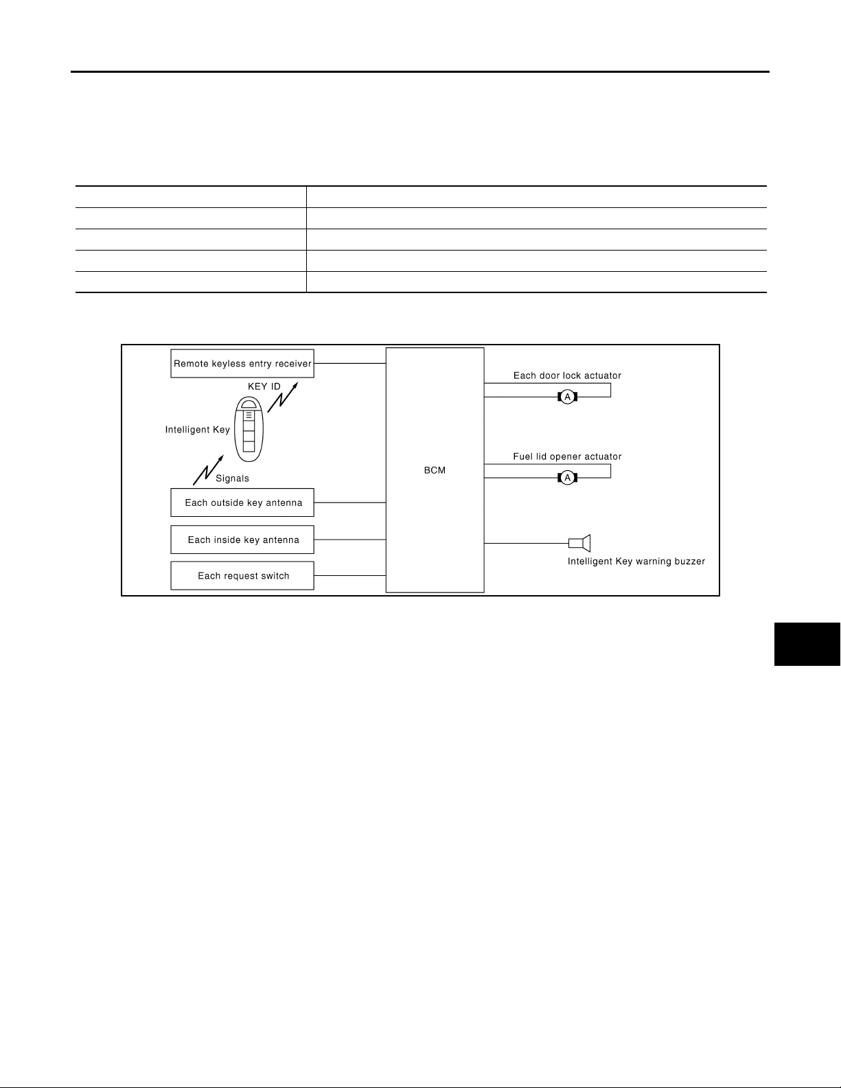
INTELLIGENT KEY : System Diagram INFOID:0000000000961095
INTELLIGENT KEY : System Description INFOID:0000000000961096
The Intelligent Key has the same functions as the remote control entry system. Therefore, it can be used in the
same manner as the remote controller by operating the door lock/unlock button.
OPERATION DESCRIPTION/DOOR LOCK/UNLOCK FUNCTION
• When door lock/unlock button of the Intelligent Key is pressed, lock signal or unlock signal is transmits from
Intelligent Key to BCM via remote keyless entry receiver .
• When BCM receives the door lock/unlock signal, it operates door lock actuator, flashes the hazard lamp
(lock: 2 time, unlock: 1 times) and horn chirp signal to IPDM E/R at the same time as a reminder.
• IPDM E/R honks horn (lock: 2 time) as a reminder
OPERATION CONDITION
Remote controller operation Operation condition Operation
Lock • All doors closed All doors lock
Unlock • Intelligent Key is out of key slot All doors unlock
JMKIA0052G
DLK-18
Page 19
DOOR LOCK FUNCTION
Revision: October 2006
2007 G35 Sedan
< FUNCTION DIAGNOSIS >
OPERATION AREA
• Operating Range
• To ensure the Intelligent Key works effectively, use within 80 cm range of each doors, however the operable
range may differ according to surroundings.
SELECTIVE UNLOCK FUNCTION
When an LOCK signal is transmitted from Intelligent Key, all doors will be locked.
When an UNLOCK signal is transmitted from Intelligent Key once, driver's door will be unlocked.
Then, if an UNLOCK signal is transmitted from Intelligent Key again within 5 seconds, all other door will be
unlocked.
HAZARD AND HORN REMINDER FUNCTION
When doors are locked or unlocked by Intelligent Key, BCM flashes hazard warning lamps as a reminder and
sends horn chirp signal to IPDM E/R. IPDM E/R sounds horn as a reminder.
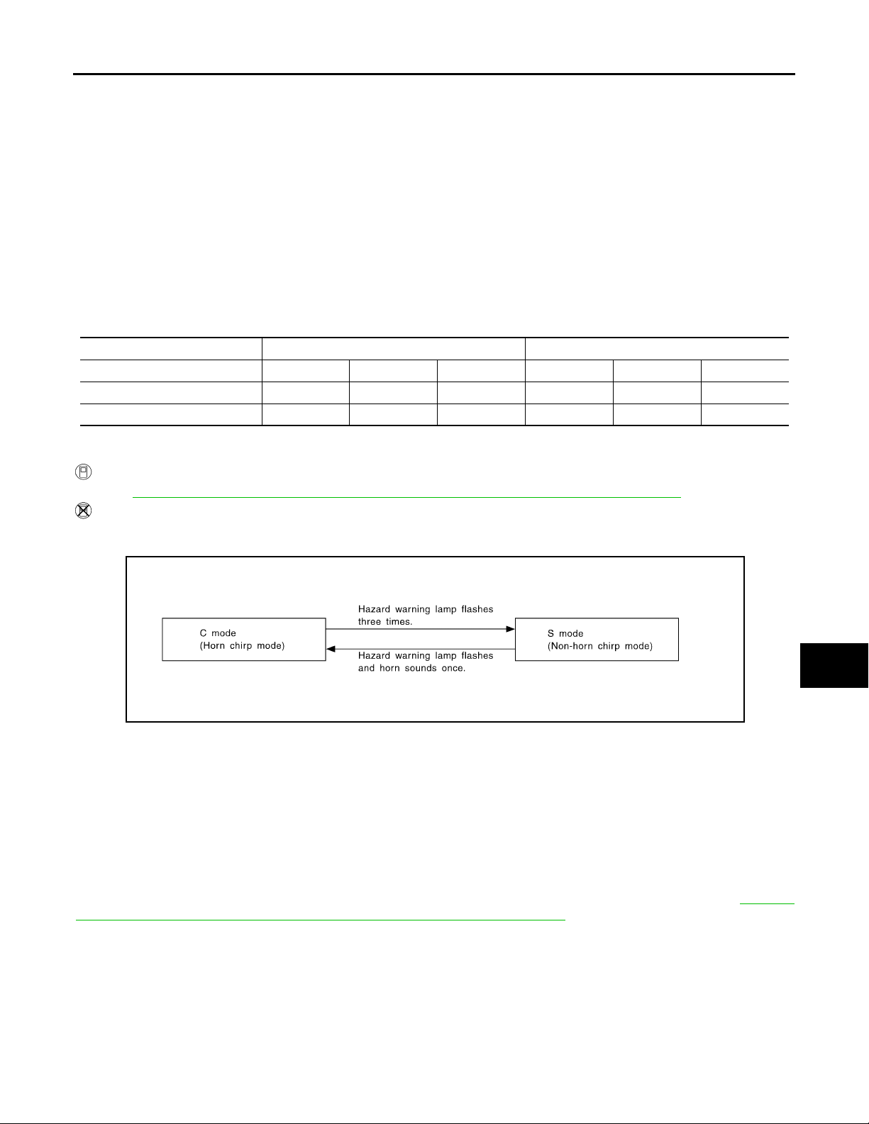
The hazard and horn reminder has a horn chirp mode (C mode) and a non-horn chirp mode (S mode).
Operating function of hazard and horn reminder
C mode S mode
Intelligent Key operation Lock Unlock Trunk open Lock Unlock Trunk open
Hazard warning lamp flash Twice Once — Twice — —
Horn sound Once—————
Hazard and horn reminder does not operate if any door switch is ON (any door is OPEN).
How to change hazard and horn reminder mode
With CONSULT-III
Refer to DLK-51, "
Without CONSULT-III
When LOCK and UNLOCK signals are sent from the Intelligent Key for more than 2 seconds at the same time,
the hazard and horn reminder mode is changed and hazard warning lamp flashes and horn sounds as follows:
INTELLIGENT KEY : CONSULT-III Function (BCM - INTELLIGENT KEY)".
[INTELLIGENT KEY SYSTEM]
A
B
C
D
E
F
G
H
I
SEL153WA
AUTO DOOR LOCK FUNCTION
Auto Door Lock Function
When all doors are locked, ignition switch is OFF (ignition switch is not pressed) and key switch is OFF (Intelligent Key is not inserted in key slot), doors are unlocked with Intelligent Key button. When BCM does not
receive the following signals within 30 seconds, all doors are locked.
• Door switch is ON (door is opened)
• Door is locked
• Ignition switch is ON
• Key switch is ON (Intelligent Key is inserted in key slot)
Auto door lock mode can be changed by “AUTO LOCK SET” mode in “WORK SUPPORT”. Refer to DLK-51,
"INTELLIGENT KEY : CONSULT-III Function (BCM - INTELLIGENT KEY)".
PANIC ALARM FUNCTION
When ignition switch is OFF (ignition switch is not pressed) and key switch is OFF (Intelligent Key is not
inserted in key slot), BCM receives PANIC ALARM signal from Intelligent Key.
BCM turns on and off headlamp intermittently and transmits theft warning horn signal to IPDM E/R. Then,
IPDM E/R turns on and off horn intermittently.
The headlamp flashes and the horn sounds intermittently.
The alarm automatically turns off:
• After 25 seconds
• When BCM receives any signal from Intelligent Key
J
DLK
L
M
N
O
P
DLK-19
Page 20

DOOR LOCK FUNCTION
Revision: October 2006
2007 G35 Sedan
< FUNCTION DIAGNOSIS >
Panic alarm function mode can be changed by “PANIC ALARM SET” mode in “WORK SUPPORT”. Refer to
DLK-51, "
INTELLIGENT KEY : CONSULT-III Function (BCM - INTELLIGENT KEY)".
KEYLESS POWER WINDOW DOWN (OPEN) FUNCTION
All power windows open when the unlock button on Intelligent Key is activated and kept pressed for more than
3 seconds with the ignition switch OFF. The windows keep opening if the unlock button is continuously
pressed.
The power window opening stops when the following operations are performed:
• When the unlock button is kept pressed more than 15 seconds.
• When the ignition switch is turned ON while the power window opening is operated.
• When the unlock button is released.
While retained power operation activate, Keyless power window down (open) function cannot be operated.
Keyless power window down operation mode can be changed by “PW DOWN SET” mode in “WORK SUPPORT”. Refer to DLK-51, "
INTELLIGENT KEY : CONSULT-III Function (BCM - INTELLIGENT KEY)".
ROOM LAMP ILLUMINATION OPERATION
When the following conditions are met:
• Condition of interior lamp switch is in DOOR position
• Door switch OFF (all the doors are closed)
Intelligent Key system turns on interior lamp (for 15 seconds) by receiving UNLOCK signal from Intelligent
Key. For detailed description, refer to INL-9, "
System Description".
LIST OF OPERATION RELATED PARTS
Parts marked with × are the parts related to operation.
[INTELLIGENT KEY SYSTEM]
Remote keyless entry functions
Intelligent Key
Key slot
Door request switch (Driver, Passenger)
Door switch
Door lock actuator
Intelligent Key warning buzzer
CAN communication system
BCM
Combination meter
Hazard warning lamp
Horn
IPDM E/R
Head lamp
Door lock/unlock function by remote control button ×× ×× ××
Hazard and horn reminder function × ЧЧЧЧЧЧЧ
Selective unlock function ×××××
Keyless power window down (open) function ×× ××
Auto door lock function ×× × ××
Panic alarm function × × ×× ×××
INTELLIGENT KEY : Component Parts Location INFOID:0000000000961097
DLK-20
Page 21
< FUNCTION DIAGNOSIS >
B
Revision: October 2006
2007 G35 Sedan
DOOR LOCK FUNCTION
[INTELLIGENT KEY SYSTEM]
A
B
C
D
E
F
G
JMKIA0142G
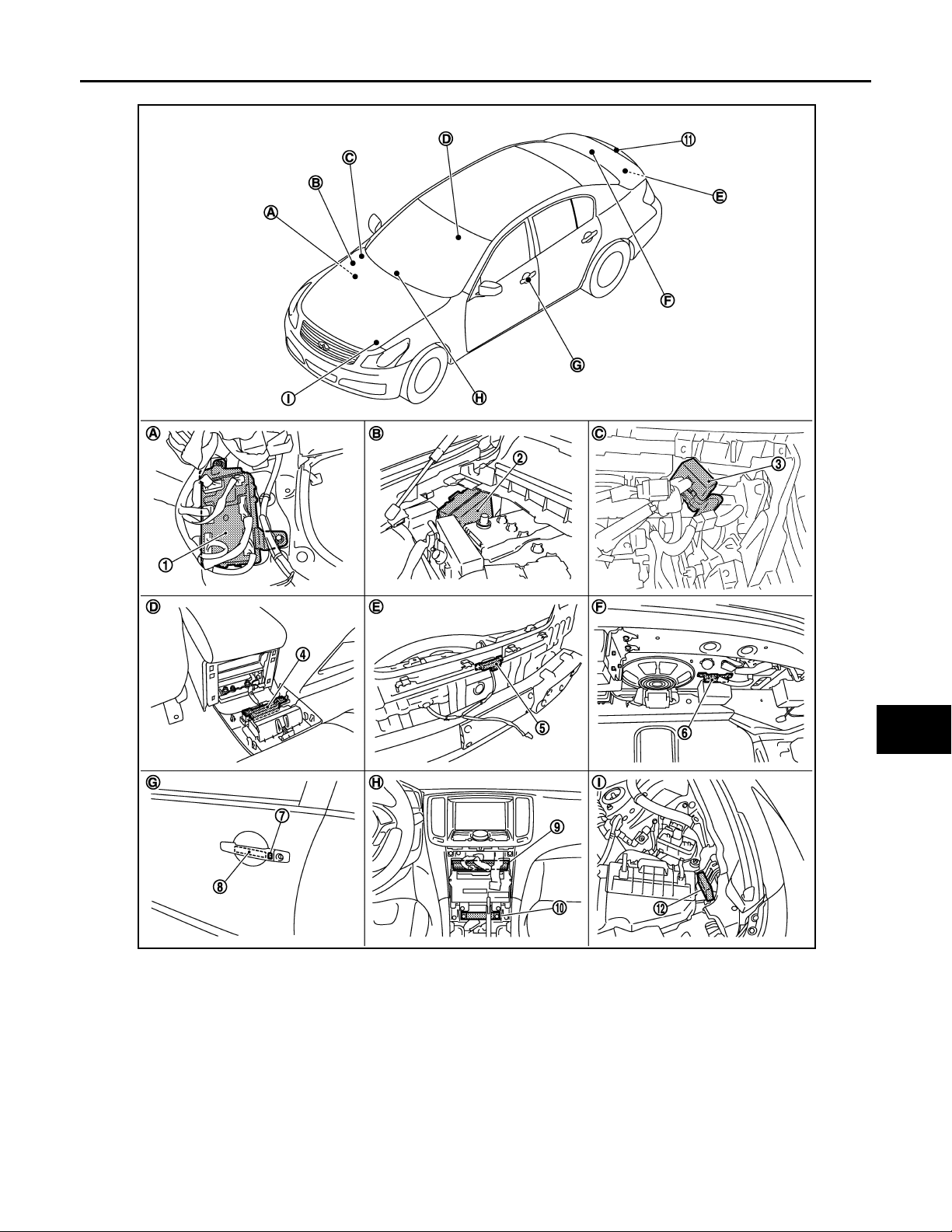
1. BCM
M118,M119,M120,M121,M122,M123
4. Inside key antenna (console) M1 46 5. Outside key antenna (rear bumper)
7. Front outside handle LH (request switch)
D13
10. Inside key antenna (instrument center)
M131
A. Dash side lower (Passenger side). B. Engine room dash panel (RH). C. View with instrument assist lower
2. IPDM E/R E5,E6 3. Remote keyless entry receiver
M104
6. Inside key antenna (trunk room)
B63
8. Front outside handle LH (o utside key
antenna) D14
11. Trunk lid request switch B304 12. Intelligent Key warning buzzer (en-
B49
9. Unified meter and A/C AMP
M66,M67
gine room) E57
panel removed.
H
I
J
DLK
L
M
N
O
P
DLK-21
Page 22
DOOR LOCK FUNCTION
B
Revision: October 2006
2007 G35 Sedan
< FUNCTION DIAGNOSIS >
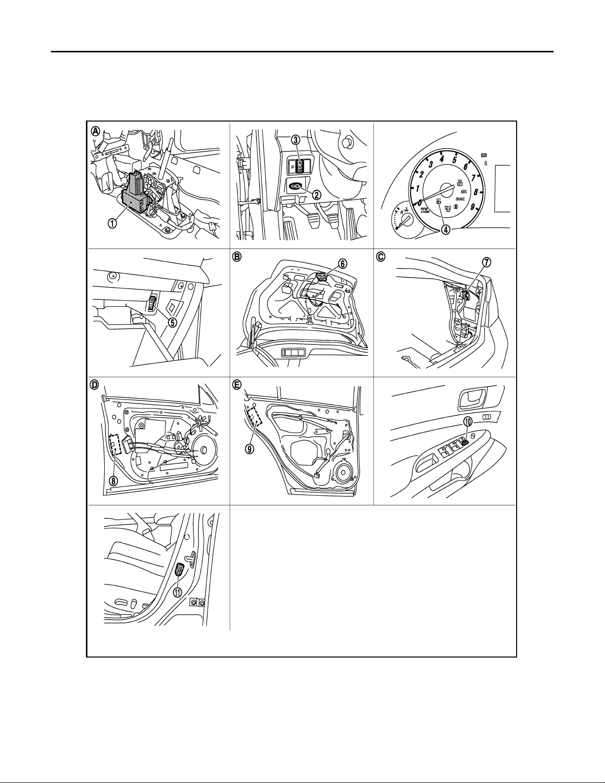
D. View with console rear finisher removed. E. View with rear bumper removed. F. View with trunk rear finisher (up-
G. View of front door LH. H. Behind cluster lid C. I. View with hood seal assembly re-
[INTELLIGENT KEY SYSTEM]
per) removed.
moved.
1. A/T device (detention switch) 2. Key slot M22 3. Trunk lid opener switch M20
4. Combination meter (Key warning lamp)
M53
7. Fuel lid opener actuator B242 8. Front door lock assembly (driver side) D15 9. Rear door lock assembly D55
10. Power window main switch (door lock unlock switch) D8,D9
JMKIA0143G
5. Trunk opener cancel switch M105 6. Trunk lid lock assembly (trunk lid
opener actuator) B303
11. Front door switch B16
DLK-22
Page 23

DOOR LOCK FUNCTION
Revision: October 2006
2007 G35 Sedan
< FUNCTION DIAGNOSIS >
A. View with center console assembly re-
moved.
D View with front door finisher removed. E View with rear door finisher removed.
B. View with trunk lid finisher removed. C. View with trunk side finisher re-
[INTELLIGENT KEY SYSTEM]
moved.
A
INTELLIGENT KEY : Component Description INFOID:0000000000961098
Item Function
BCM Controls the door lock function and room lamp function.
Door lock actuator Receives lock/unlock signal from BCM and locks/unlocks each door.
Remote keyless entry receiver Receives lock/unlock signal from the Intelligent Key, and then transmits to BCM.
Intelligent Key Transmit s button operation to remote keyless entry receiver.
Fuel lid opener actuator Performs lock/unlock of the fuel lid.
Intelligent key warning buzzer Warns the user of the lock/unlock condition and inappropriate operations with the buzzer sound.
B
C
D
E
F
G
H
I
J
DLK
L
M
N
O
P
DLK-23
Page 24
TRUNK OPEN FUNCTION
B
Revision: October 2006
2007 G35 Sedan
< FUNCTION DIAGNOSIS >
[INTELLIGENT KEY SYSTEM]
TRUNK OPEN FUNCTION
TRUNK LID OPENER SWITCH
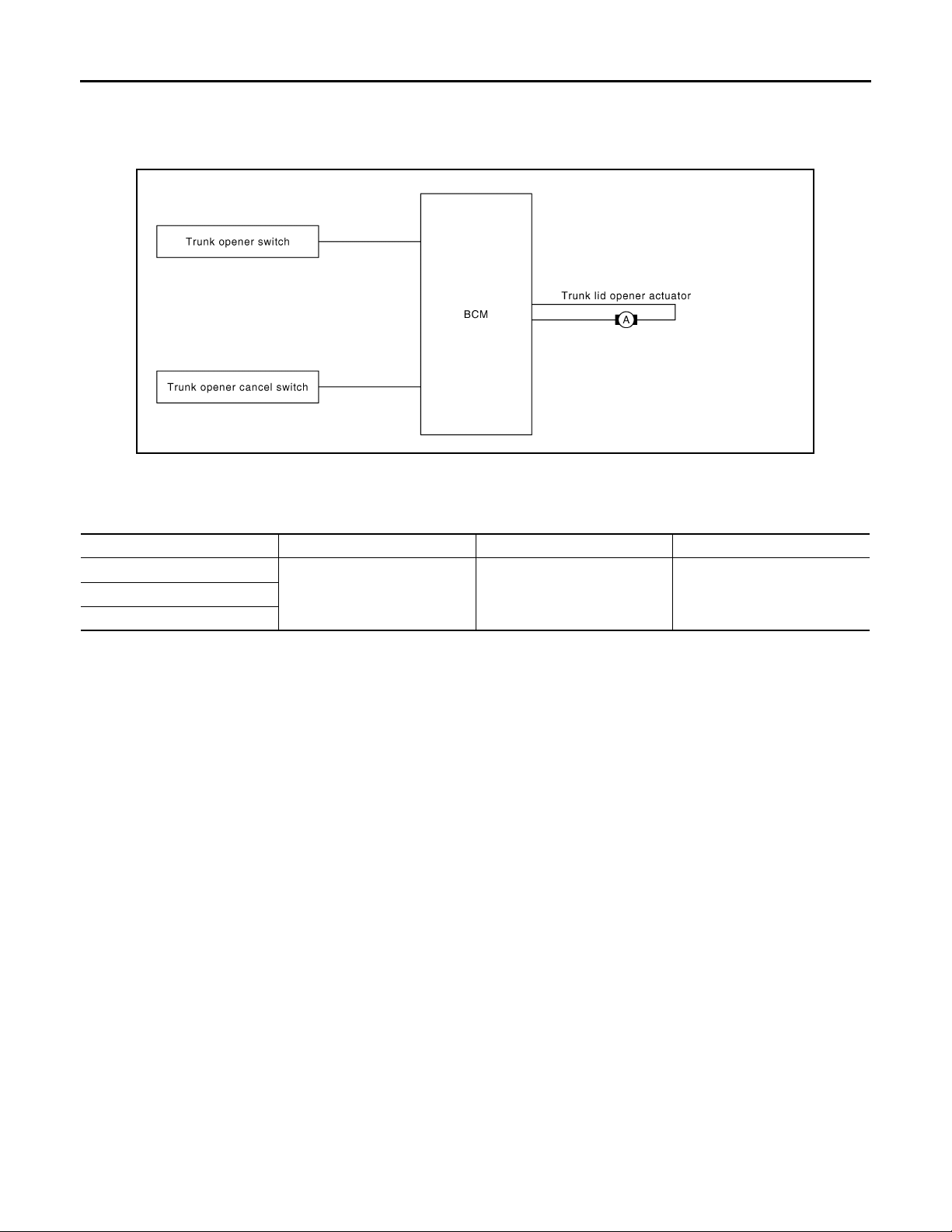
TRUNK LID OPENER SWITCH : System Diagram INFOID:0000000000961099
JMKIA0053G
TRUNK LID OPENER SWITCH : System Description INFOID:0000000000961100
Switch Input/output signal to BCM BCM function Actuator
Trunk lid opener switch
Trunk open signal Trunk open control Trunk lid opener actuatorTrunk lid opener ca ncel switch
Door key cylinder switch
TRUNK LID OPENER OPERATION
When trunk lid opener switch is ON, BCM opens trunk opener actuator.
BCM can open trunk lid opener actuator when
• vehicle speed is less than 5 km/h (3MPH)
• vehicle security system is disarmed or pre-armed phase
BCM does not open trunk lid opener actuator when
• trunk lid opener cancel switch is OFF (CANCEL)
• vehicle speed is more than 5 km/h (3MPH)
• vehicle security system is armed or alarm phase
• Intelligent Key is inserted in key slot
TRUNK LID OPENER SWITCH : Component Parts Location INFOID:0000000000961101
DLK-24
Page 25
< FUNCTION DIAGNOSIS >
B
Revision: October 2006
2007 G35 Sedan
TRUNK OPEN FUNCTION
[INTELLIGENT KEY SYSTEM]
A
B
C
D
E
F
G
JMKIA0142G
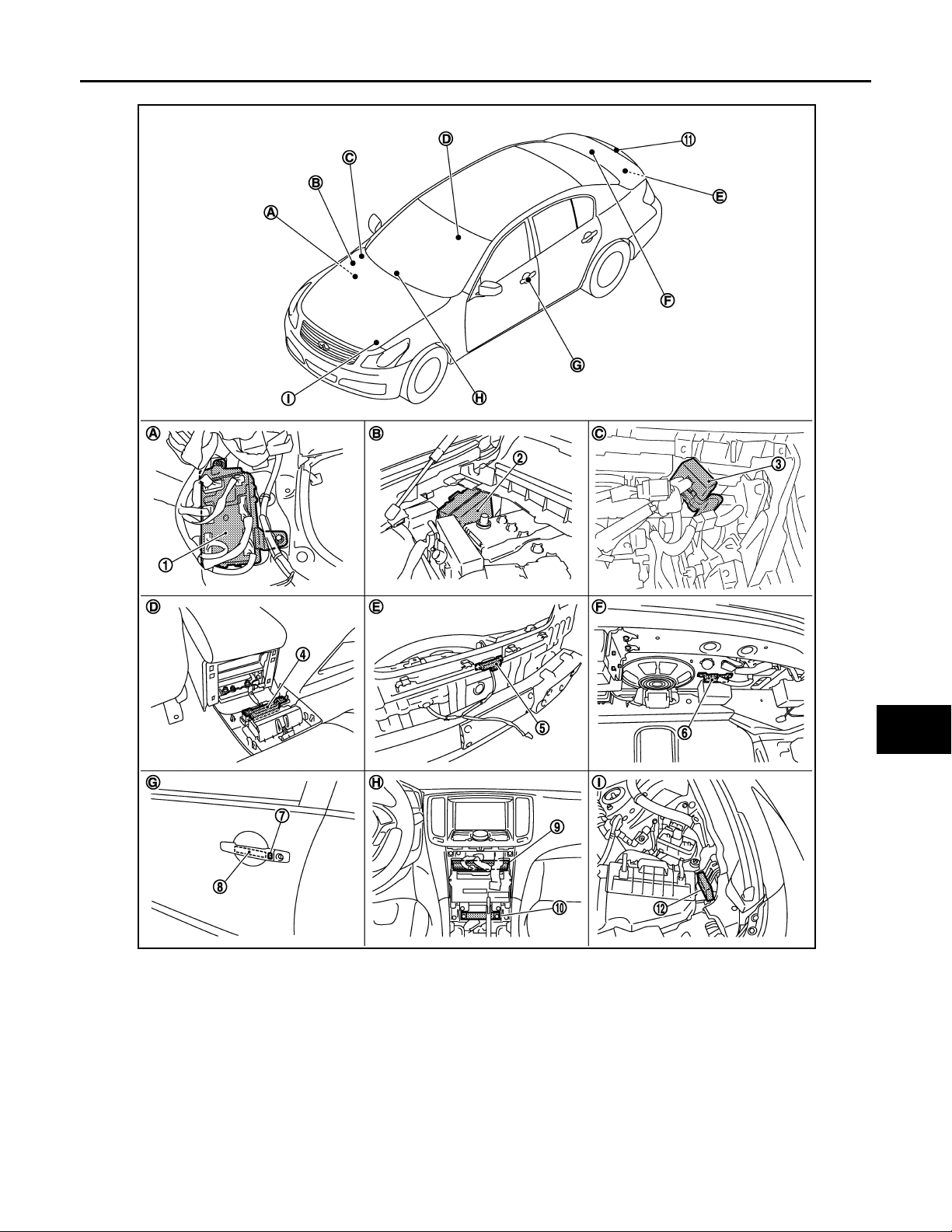
1. BCM
M118,M119,M120,M121,M122,M123
4. Inside key antenna (console) M1 46 5. Outside key antenna (rear bumper)
7. Front outside handle LH (request switch)
D13
10. Inside key antenna (instrument center)
M131
A. Dash side lower (Passenger side). B. Engine room dash panel (RH). C. View with instrument assist lower
2. IPDM E/R E5,E6 3. Remote keyless entry receiver
M104
6. Inside key antenna (trunk room)
B63
8. Front outside handle LH (o utside key
antenna) D14
11. Trunk lid request switch B304 12. Intelligent Key warning buzzer (en-
B49
9. Unified meter and A/C AMP
M66,M67
gine room) E57
panel removed.
H
I
J
DLK
L
M
N
O
P
DLK-25
Page 26
TRUNK OPEN FUNCTION
B
Revision: October 2006
2007 G35 Sedan
< FUNCTION DIAGNOSIS >
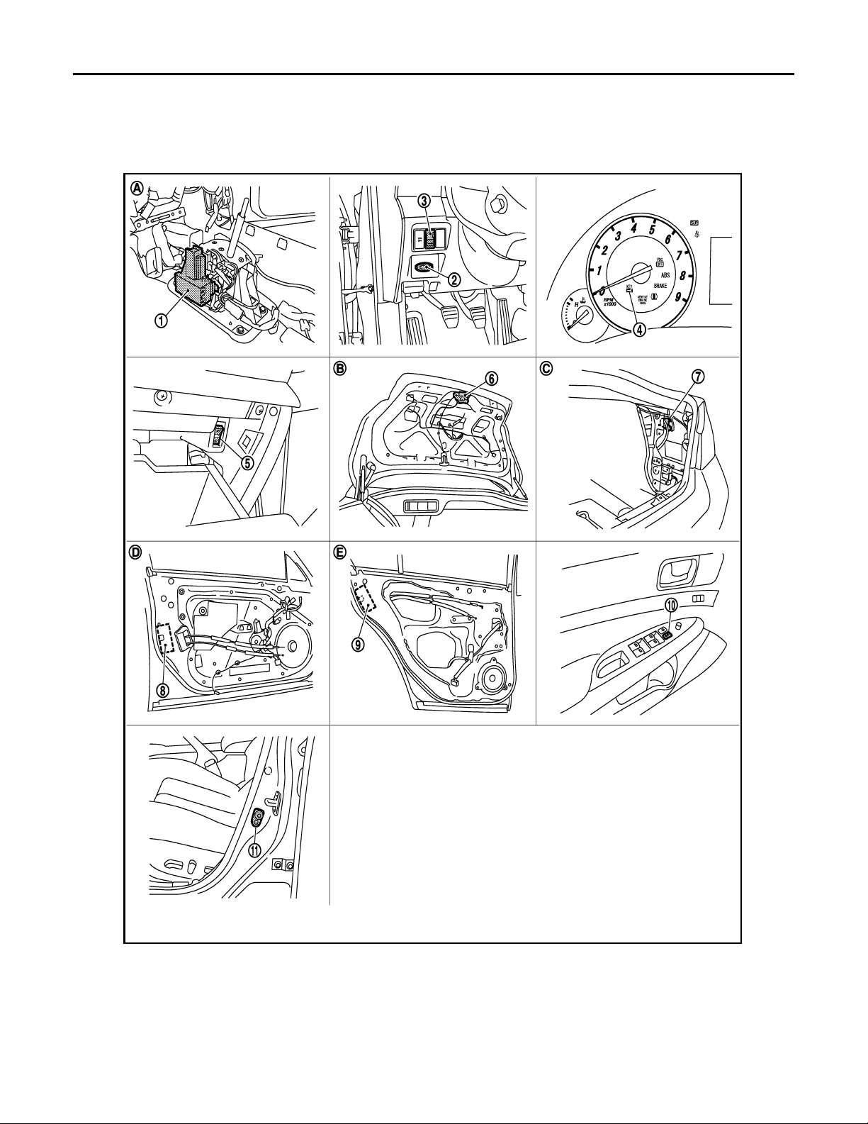
D. View with console rear finisher removed. E. View with rear bumper removed. F. View with trunk rear finisher (up-
G. View of front door LH. H. Behind cluster lid C. I. View with hood seal assembly re-
[INTELLIGENT KEY SYSTEM]
per) removed.
moved.
1. A/T device (detention switch) 2. Key slot M22 3. Trunk lid opener switch M20
4. Combination meter (Key warning lamp)
M53
7. Fuel lid opener actuator B242 8. Front door lock assembly (driver side) D15 9. Rear door lock assembly D55
10. Power window main switch (door lock unlock switch) D8,D9
JMKIA0143G
5. Trunk opener cancel switch M105 6. Trunk lid lock assembly (trunk lid
opener actuator) B303
11. Front door switch B16
DLK-26
Page 27
TRUNK OPEN FUNCTION
B
Revision: October 2006
2007 G35 Sedan
< FUNCTION DIAGNOSIS >
A. View with center console assembly re-
moved.
D View with front door finisher removed. E View with rear door finisher removed.
B. View with trunk lid finisher removed. C. View with trunk side finisher re-
[INTELLIGENT KEY SYSTEM]
moved.
A
TRUNK LID OPENER SWITCH : Component Description INFOID:0000000000961102
Item Function
BCM Transmits trunk open operation to BCM.
Trunk lid opener switch Transmits trunk open operation to BCM.
Trunk lid opener actuator Opens the trunk with the open signal from BCM
Trunk lid opener cancel switch Cancels the trunk open operation.
TRUNK REQUEST SWITCH
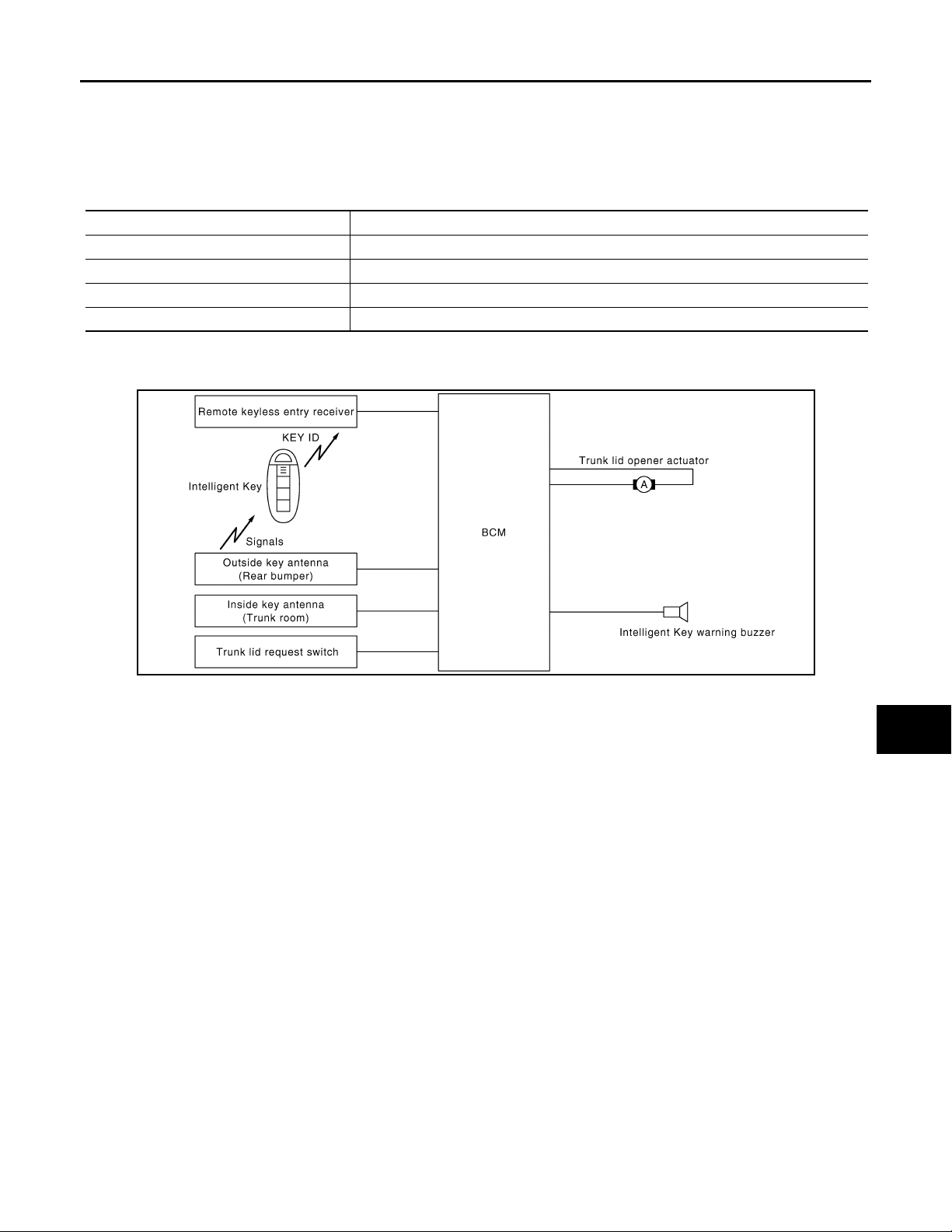
TRUNK REQUEST SWITCH : System Diagram INFOID:0000000000961103
B
C
D
E
F
G
H
I
JMKIA0054G
TRUNK REQUEST SWITCH : System Description INFOID:0000000000961104
Only when pressing the request switch, it is possible to open the trunk by carrying the Intelligent Key.
• The Intelligent Key system is a system that makes it possible to open the trunk (trunk open function) by carrying the Intelligent Key which operates based on the results of electronic ID verification using two-way communications between the Intelligent Key and the vehicle. (BCM)
CAUTION:
The driver should always carry the Intelligent Key
• If an action that does not meet the operating conditions of the Intelligent Key system is taken, the buzzer
goes off to inform the driver. (Warning chime functions)
• When a trunk open with request switch or remote controller button operation, the hazard lamps flash and the
Intelligent Key warning buzzer or horn sounds (Hazard and buzzer/horn reminder function).
• The settings for each function can be changed with the CONSULT-III.
• If an Intelligent Key is lost, a new Intelligent Key can be registered. A maximum of 4 Intelligent Keys can be
registered.
• It is possible to perform a diagnosis on the system and register an Intelligent Key with the CONSULT-III.
OPERATION DESCRIPTION/TRUNK OPEN
• When the BCM detects that trunk open request switch is pressed, it starts the outside key antenna (trunk
room) and inside key antenna corresponding to the pressed trunk open request switch and transmits the
request signal to the Intelligent Key. And then, check that the Intelligent Key is near the trunk.
• If the Intelligent Key is within the outside key antenna (trunk room) detection area, it receives the request signal and transmits the key ID signal to the BCM via remote keyless entry receiver.
• BCM receives the key ID signal and compares it with the registered key ID.
• BCM transmits the trunk open request signal and sounds Intelligent Key warning buzzer 4 times at the same
time.
J
DLK
L
M
N
O
P
DLK-27
Page 28
TRUNK OPEN FUNCTION
B
Revision: October 2006
2007 G35 Sedan
< FUNCTION DIAGNOSIS >
• When BCM receives the trunk open request signal, it operates the trunk lid opener actuator and opens the
trunk.
OPERATION CONDITION
If the following conditions are not satisfied, trunk open operation is not performed even if the request switch is
operated.
Each request switch operation Operation condition
• Intelligent Key is within outside key antenna (trunk room) detection area*
Trunk open operation
*: Even with a registered Intelligent Key remaining inside the vehicle, door locks can be unlocked from outside of the vehicle with a spare
Intelligent Key as long as key IDs are different.
• Trunk cancel switch is ON
• Key reminder functions operate (trunk)
OUTSIDE KEY ANTENNA DETECTION AREA
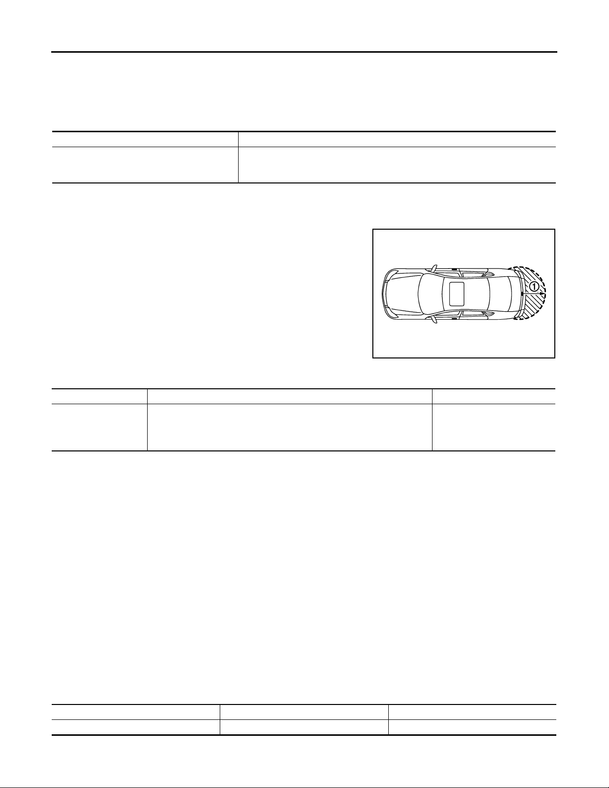
The outside key antenna detection area of trunk open function is in
the range of approximately 80 cm (31.50 in) surrounding Trunk
opener request switch (1). However, this operating range depends
on the ambient conditions.
[INTELLIGENT KEY SYSTEM]
JMKIA0102G
KEY REMINDER FUNCTION
Key remainder function Operation condition Operation
Right after trunk is closed under the following conditions
Trunk is closed
*:If the door closing imp act s hock s the door lo ck kno b, or cont ac t s ag ainst bagg age wit h th e door lock knob mi ght a ctiva te t he do or locks
accidentally but unlock operation will be perform at these cases.
• Intelligent Key is inside trunk room
• All doors are closed
• All doors are locked
• Trunk open
• Honk Intelligent Key warning
buzzer
CAUTION:
• The above function operates when the Intelligent Key is inside the vehicle. However, there may be
times when the Intelligent Key cannot be detected, and this function will not operate when the Intelligent Key is on the instrument panel, rear parcel shelf, or in the glove box. Also, this system sometimes does not operate if the Intelligent Key is in the door pocket for the open door.
• When the key reminder function is operated when the trunk is opened/closed and the buzzers
sound, if the following operations are performed, the key reminder function is cleared and buzzer
sounds are stopped.
- Remote controller door lock button operation of Intelligent Key
- Remote controller door unlock button operation of Intelligent Key
- When the trunk is closed, the Intelligent Key is not inside the vehicle
- When any door is open
HAZARD AND BUZZER REMINDER FUNCTION
During trunk opening operation by request switch, the hazard warning lamps and Intelligent Key warning
buzzer will flash or honk as a reminder.
When trunk open by each request switch, IPDM E/R honks Intelligent Key warning buzzer as a reminder and
transmits hazard request signal to BCM via CAN communication line.
BCM flashes hazard warning lamps as a reminder.
Operating function of hazard and buzzer reminder
Operation Hazard warning lamp flash Intelligent Key warning buzzer honk
Trunk open — Fourth
How to change hazard and buzzer reminder mode
DLK-28
Page 29

< FUNCTION DIAGNOSIS >
Revision: October 2006
2007 G35 Sedan
TRUNK OPEN FUNCTION
[INTELLIGENT KEY SYSTEM]
With CONSULT-III
Refer to DLK-51, "
INTELLIGENT KEY : CONSULT-III Function (BCM - INTELLIGENT KEY)".
LIST OF OPERATION RELATED PARTS
Parts marked with × are the parts related to operation.
Trunk open function
Intelligent Key
Key slot
Remote keyless entry receiver
Door switch
Trunk room lamp switch
Trunk opener request switch
Trunk lid opener actuator
Inside key antenna
Outside key antenna (Trunk)
Intelligent Key warning buzzer
CAN communication system
BCM
Hazard warning lamp
Trunk open function by the trunk opener request switch ××× ЧЧЧЧЧ ×× ×
Hazard and buzzer reminder function for door lo ck/unlock
operation
Buzzer reminder for trunk open operation ×××
Key reminder function ×××× ЧЧЧЧЧЧ
××××
TRUNK REQUEST SWITCH : Component Parts Location INFOID:0000000000961105
Trunk lid opener cancel switch
A
B
C
D
E
F
G
H
I
J
DLK
L
M
N
O
P
DLK-29
Page 30
< FUNCTION DIAGNOSIS >
B
Revision: October 2006
2007 G35 Sedan
TRUNK OPEN FUNCTION
[INTELLIGENT KEY SYSTEM]
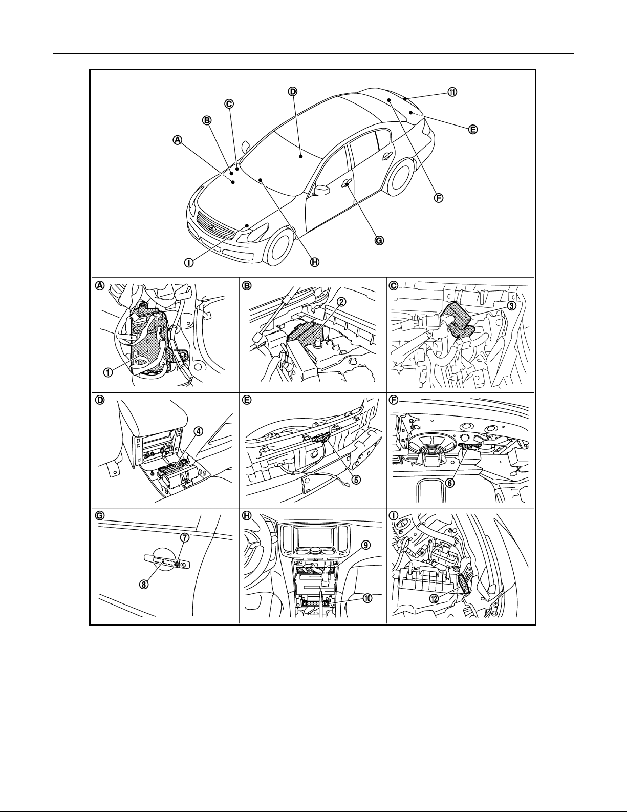
1. BCM
M118,M119,M120,M121,M122,M123
4. Inside key antenna (console) M146 5. Outside key antenna (rear bumper)
7. Front outside handle LH (request switch)
D13
10. Inside key antenna (instrument center)
M131
A. Dash side lower (Passenger side). B. Engine room dash panel (RH). C. View with instrument assist lower
JMKIA0142G
2. IPDM E/R E5,E6 3. Remote keyless entry receiver
M104
6. Inside key antenna (trunk room)
B63
8. Front outside handle LH (outside key
antenna) D14
11. Trunk lid request switch B304 12. Intelligent Key warning buzzer (en-
B49
9. Unified meter and A/C AMP
M66,M67
gine room) E57
panel removed.
DLK-30
Page 31
TRUNK OPEN FUNCTION
B
Revision: October 2006
2007 G35 Sedan
< FUNCTION DIAGNOSIS >
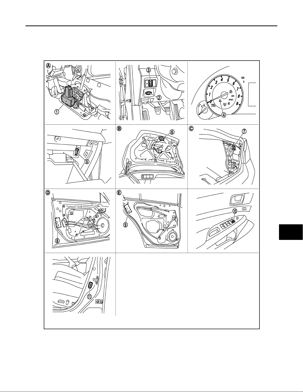
D. View with console rear finisher removed. E. View wit h rear bumper removed. F. View with trunk rear finisher (up-
G. View of front door LH. H. Behind cluster lid C. I. View with hood seal assembly re-
[INTELLIGENT KEY SYSTEM]
per) removed.
moved.
A
B
C
D
E
F
G
H
I
J
DLK
L
M
N
O
1. A/T device (detention switch) 2. Key slot M22 3. Trunk lid opener switch M20
4. Combination meter (Key warning lamp)
M53
7. Fuel lid opener actuator B242 8. Front door lock assembly (driver side) D15 9. Rear door lock assembly D55
10. Power window main switch (door lock unlock switch) D8,D9
JMKIA0143G
P
5. Trunk opener cancel switch M105 6. Trunk lid lock assembly (trunk lid
opener actuator) B303
11. Front door switch B16
DLK-31
Page 32
TRUNK OPEN FUNCTION
B
Revision: October 2006
2007 G35 Sedan
< FUNCTION DIAGNOSIS >
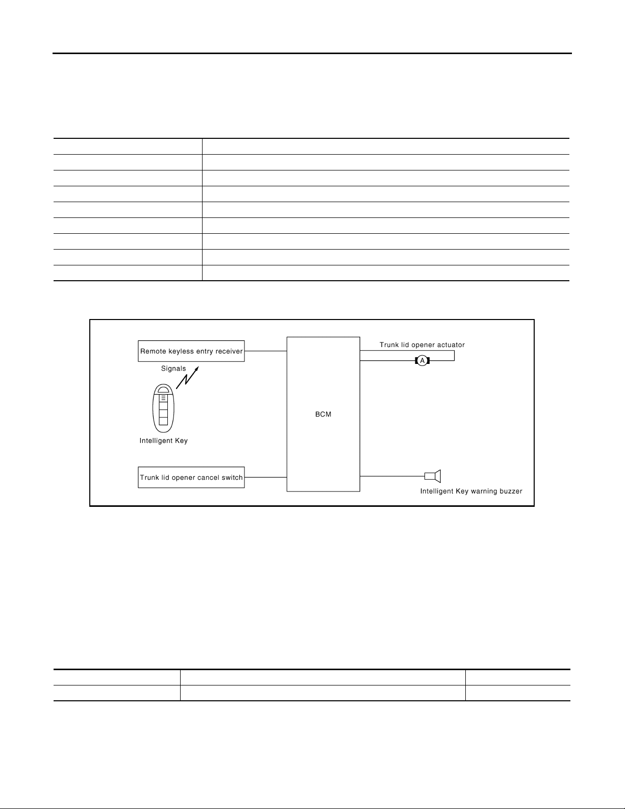
A. View with center console assembly re-
moved.
D View with front door finisher removed. E View with rear door finisher removed.
B. View with trunk lid finisher removed. C. View with trunk side finisher re-
[INTELLIGENT KEY SYSTEM]
moved.
TRUNK REQUEST SWITCH : Component Description
Item Function
BCM Controls trunk open function.
Trunk lid opener actuator Transmits trunk open operation to BCM.
Remote keyless entry receiver Receives lock/unlock signal from the Intelligent Key, and then transmits to BCM.
Trunk request switch Transmits trunk open operation to BCM.
Intelligent Key Transmits button operation to remote keyless entry receiver.
Outside key antenna Detects if Intelligent Key is outside the vehicle.
Inside key antenna Detects if Intelligent Key is inside the vehicle.
Intelligent Key warning buzzer W arns the user of th e lock/unlock condition an d inappropriate operatio ns with the buzzer sound.
INFOID:0000000000961106
INTELLIGENT KEY
INTELLIGENT KEY : System Diagram INFOID:0000000000961107
INTELLIGENT KEY : System Description INFOID:0000000000961108
The Intelligent Key has the same functions as the remote control entry system. Therefore, it can be used in the
same manner as the remote controller by operating the trunk open button.
OPERATION DESCRIPTION/TRUNK OPEN FUNCTION
• When trunk button of the Intelligent Key is pressed, the trunk open signal is transmitted from the Intelligent
Key to the BCM via remote keyless entry receiver.
• When BCM receives the trunk open request signal, it operates the trunk lid opener actuator and opens the
trunk.
OPERATION CONDITION
Remote controller operation Operation condition Operation
Trunk open • Press and hold the trunk open button for 0.5 second or more Trunk open
OPERATION AREA
• Operating Range
• To ensure the Intelligent Key works effectively, use within 80 cm range of each door, however the operable
range may differ according to surroundings.
HAZARD AND HORN REMINDER FUNCTION
JMKIA0055G
DLK-32
Page 33
TRUNK OPEN FUNCTION
Revision: October 2006
2007 G35 Sedan
< FUNCTION DIAGNOSIS >
When doors are locked or unlocked by Intelligent Key. BCM flashes hazard warning lamps as a reminder and
transmits horn chirp signal to IPDM E/R. IPDM E/R sounds horn as a reminder.
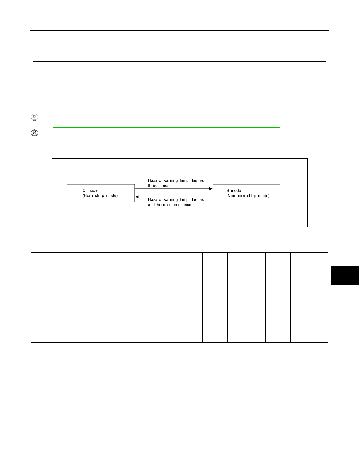
The hazard and horn reminder has a horn chirp mode (C mode) and a non-horn chirp mode (S mode).
Operating function of hazard and horn reminder
C mode S mode
Intelligent Key operation Lock Unlock Trunk open Lock Unlock Trunk open
Hazard warning lamp flash Twice Once — Twice — —
Horn sound Once—————
Hazard and horn reminder does not operate if any door switch is ON (any door is OPEN).
How to change hazard and horn reminder mode
With CONSULT-III
Refer toDLK-51, "
INTELLIGENT KEY : CONSULT-III Function (BCM - INTELLIGENT KEY)".
Without CONSULT-III
When LOCK and UNLOCK signals are transmitted from the Intelligent Key for more than 2 seconds at the
same time, the hazard and horn reminder mode is changed and hazard warning lamp flashes and horn
sounds as follows:
[INTELLIGENT KEY SYSTEM]
A
B
C
D
E
F
G
SEL153WA
LIST OF OPERATION RELATED PARTS
Parts marked with × are the parts related to operation.
Remote keyless entry functions
Intelligent Key
Key slot
Trunk room lamp switch
Trunk lid opener actuator
Intelligent Key warning buzzer
CAN communication system
BCM
Combination meter
Hazard warning lamp
Horn
IPDM E/R
Head lamp
Trunk open function by remote control button ×××× ××
Hazard and horn reminder function × ЧЧЧЧЧЧЧ
INTELLIGENT KEY : Component Parts Location INFOID:0000000000961109
H
I
J
DLK
L
M
N
O
P
DLK-33
Page 34
< FUNCTION DIAGNOSIS >
B
Revision: October 2006
2007 G35 Sedan
TRUNK OPEN FUNCTION
[INTELLIGENT KEY SYSTEM]
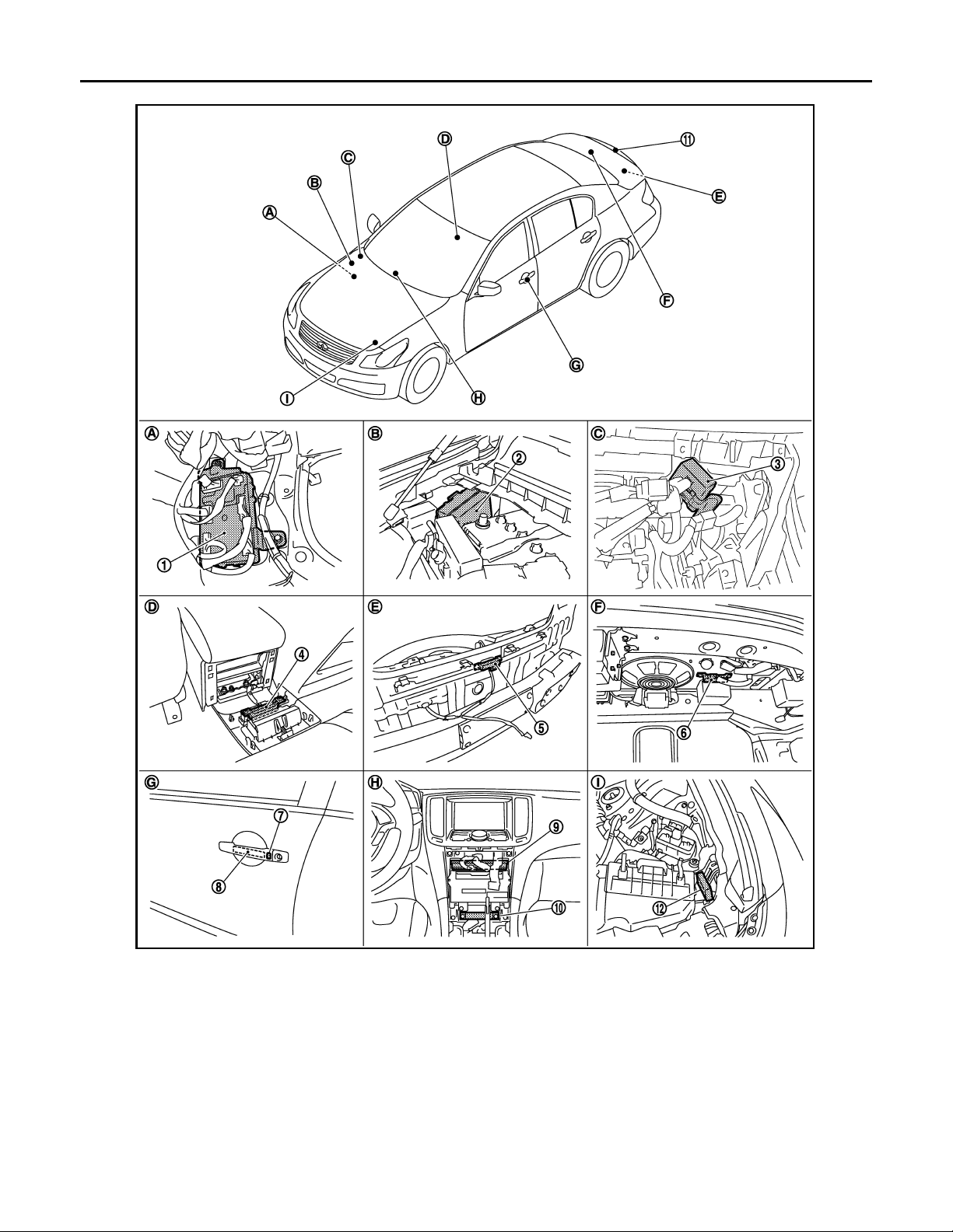
1. BCM
M118,M119,M120,M121,M122,M123
4. Inside key antenna (console) M146 5. Outside key antenna (rear bumper)
7. Front outside handle LH (request switch)
D13
10. Inside key antenna (instrument center)
M131
A. Dash side lower (Passenger side). B. Engine room dash panel (RH). C. View with instrument assist lower
JMKIA0142G
2. IPDM E/R E5,E6 3. Remote keyless entry receiver
M104
6. Inside key antenna (trunk room)
B63
8. Front outside handle LH (outside key
antenna) D14
11. Trunk lid request switch B304 12. Intelligent Key warning buzzer (en-
B49
9. Unified meter and A/C AMP
M66,M67
gine room) E57
panel removed.
DLK-34
Page 35
TRUNK OPEN FUNCTION
B
Revision: October 2006
2007 G35 Sedan
< FUNCTION DIAGNOSIS >
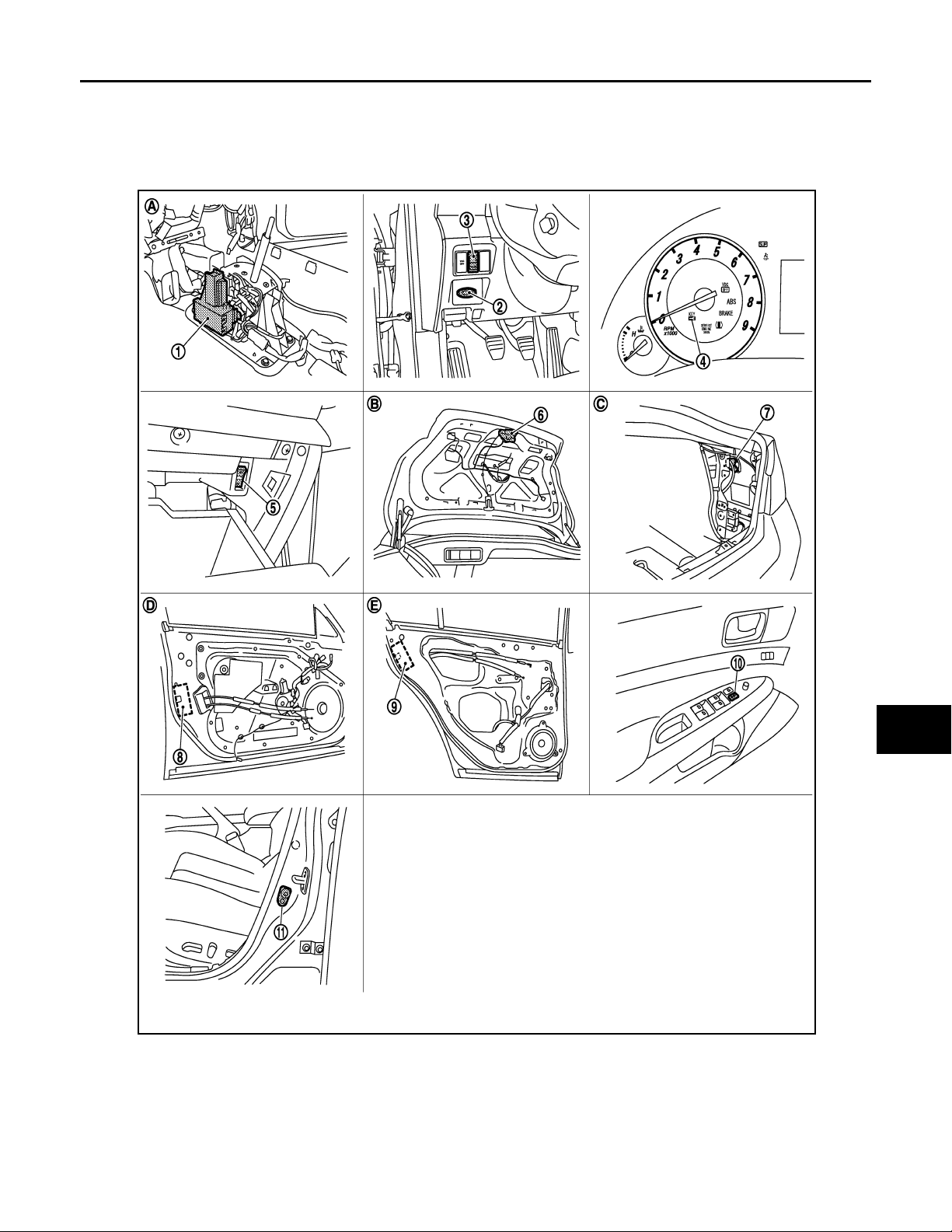
D. View with console rear finisher removed. E. View wit h rear bumper removed. F. View with trunk rear finisher (up-
G. View of front door LH. H. Behind cluster lid C. I. View with hood seal assembly re-
[INTELLIGENT KEY SYSTEM]
per) removed.
moved.
A
B
C
D
E
F
G
H
I
J
DLK
L
M
N
O
1. A/T device (detention switch) 2. Key slot M22 3. Trunk lid opener switch M20
4. Combination meter (Key warning lamp)
M53
7. Fuel lid opener actuator B242 8. Front door lock assembly (driver side) D15 9. Rear door lock assembly D55
10. Power window main switch (door lock unlock switch) D8,D9
JMKIA0143G
P
5. Trunk opener cancel switch M105 6. Trunk lid lock assembly (trunk lid
opener actuator) B303
11. Front door switch B16
DLK-35
Page 36

TRUNK OPEN FUNCTION
Revision: October 2006
2007 G35 Sedan
< FUNCTION DIAGNOSIS >
A. View with center console assembly re-
moved.
D View with front door finisher removed. E View with rear door finisher removed.
B. View with trunk lid finisher removed. C. View with trunk side finisher re-
[INTELLIGENT KEY SYSTEM]
moved.
INTELLIGENT KEY : Component Description
Item Function
BCM Controls trunk open function.
Trunk lid opener actuator Opens the trunk with the open signal from BCM.
Remote keyless entry receiver Receives trunk open signal from the Intelligent Key, and then transmits to BCM.
Intelligent Key Transmits button operation to remote keyless entry receiver.
Intelligent Key warning buzzer Warns the user of the lock/unlock c ondition and inappropriate operations wit h the buzzer s ound.
INFOID:0000000000961110
DLK-36
Page 37

< FUNCTION DIAGNOSIS >
Revision: October 2006
2007 G35 Sedan
WARNING FUNCTION
[INTELLIGENT KEY SYSTEM]
WARNING FUNCTION
System Description INFOID:0000000000961111
OPERATION DESCRIPTION
The warning function are as follows and are given to the user as warning information and warnings using combinations of Intelligent Key warning buzzer, KEY warning lamp, key slot illumination and combination meter
display in combination meter.
• Intelligent Key system malfunction
• OFF position warning
• P position warning
• ACC warning
• Take away warning
• Door lock operation warning
• Key warning
• Intelligent Key insert information
• Engine start information
• Steering lock information
• Intelligent key low battery warning
• Key ID warning
OPERATION CONDITION
Once the following condition from below is established, alert or warning will be executed.
Warning/Information functions Operation procedure
Intelligent Key system malfunction When a malfunction is detected on BCM, “KEY” warning lamp will illuminate.
• Ignition switch: ACC position.
• Door switch (driver side): ON (Door is open).
OFF position warning (For internal) is in active mode, driver side door has
been closed.
NOTE:
OFF position (For external) active only when each of the sequence has occurred as below: P position warning → ACC warning → OFF position warning
(For internal) → OFF position warning (For internal)
• Shift position: Except P position
• Engine is running to stopped (Ignition switch is ON to OFF)
• During P position warning is in active mode, shift position has changed P position.
• Ignition switch: Except OFF position.
• Ignition switch: Except LOCK position.
• Door switch: ON to OFF (Door is open to close).
• Intelligent Key can not be detected inside the vehicle.
• Door switch: ON (Door is open)
• Key ID verification every 5 seconds when registered Intelligent Key can not
be detected inside the vehicle.
• Ignition switch: Except LOCK position.
• Press ignition switch.
• Intelligent Key can not be detected inside the vehicle.
• Engine is running.
• Key ID verification every 30 seconds when registered Intelligent Key can not
be detected inside the vehicle.
• After vehicle speed verification, the registered Intelligent Key can not be detect inside the vehicle.
• When Intelligent Key is removed from key slot, Intelligent Key can not be detected inside the vehicle.
OFF position warning
P position warning
ACC warning
Take away warning
For internal
For external
Door is open to close
Door is open
Push-ignition switch operation
Take away through window
Intelligent Key is removed
from key slot
A
B
C
D
E
F
G
H
I
J
DLK
L
M
N
O
P
DLK-37
Page 38
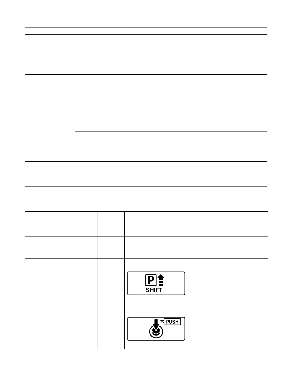
WARNING FUNCTION
B
B
Revision: October 2006
2007 G35 Sedan
< FUNCTION DIAGNOSIS >
Warning/Information functions Operation procedure
When request switch is pushed (lock opera tion) under the following co nditions.
Request switch operation
Door lock operation warning
Key warning
Intelligent Key insert information
Engine start information
Steering lock information When steering lock can not be released after ignition switch is turned ON.
Intelligent Key low battery warning
Key ID warning
Intelligent Key button operation
Ignition switch is ON position
Ignition switch is except
ON position
• Door switch: ON (Any door is open).
• Intelligent Key is inside vehicle.
When Intelligent Key button is pushed (lock operation) under the following conditions.
• Door switch: ON (Any door is open).
• For 3 seconds after Intelligent Key is removed from key slot.
• Ignition switch is OFF position.
• Driver side door switch: ON (Driver side door is open).
• Intelligent Key is inserted in key slot.
• Door switch: ON to OFF (Door is open to close).
• Ignition switch: OFF to ON posit ion .
• Intelligent Key is out of key slot.
• Intelligent Key can not be detected inside t he vehicle.
• Ignition switch: ON position.
• Shift position: P position
• Engine is stopped
• Ignition switch: Except ON position.
• Shift position: P position
• Intelligent Key is inserted in key slot.
• Intelligent Key can be detected inside the vehicle.
When Intelligent Key is low battery, BCM is detected after ignition switch is
turned ON.
When registered intelligent Key can not be detected inside the vehicle after ignition switch is turned ON.
[INTELLIGENT KEY SYSTEM]
WARNING METHOD
The following table shows the alarm or warning methods with chime.
Meter display, “KEY” indicator or key slot illumination when the warning conditions are met.
Warning chime
Warning/Information functions
Intelligent Key system malfunction Illuminate — — — —
OFF position warn-
ing
P position warning — — Activate —
ACC warning — — Activate —
For internal — — — Activate —
For external — — — — Activate
“KEY” warn-
ing lamp
Combination meter display
JMKIA0037G
Key slot illumination
Combination
meter buzzer
Intelligent
Key warning
buzzer
JMKIA0047G
DLK-38
Page 39
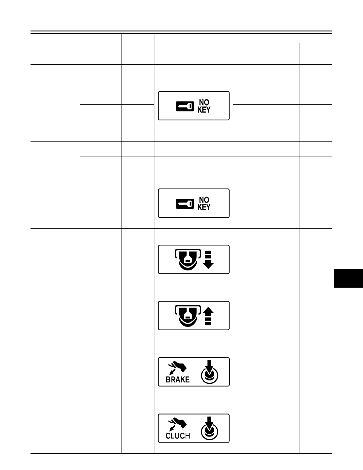
< FUNCTION DIAGNOSIS >
B
B
B
B
B
B
Revision: October 2006
2007 G35 Sedan
WARNING FUNCTION
[INTELLIGENT KEY SYSTEM]
Warning chime
Warning/Information functions
Door is open to
close
Door is open — Flash — —
Push-ignition
Take away warning
Door lock operation
warning
Key ID warning — — — —
switch operation
Take away
through window
Intelligent Key is
removed from
key slot
Request switch
operation
Intelligent Key
operation
“KEY” warn-
ing lamp
— Flash Activate Activate
—FlashActivate—
—FlashActivate—
—Flash——
————Activate
————Activate
Combination meter display
JMKIA0036G
Key slot illumination
Combination
meter buzzer
Intelligent
Key warning
buzzer
A
B
C
D
E
F
G
H
JMKIA0036G
Key warning — Flash Activate —
JMKIA0035G
Intelligent Key insert information — Flash — —
JMKIA0034G
Automatic transmission models
Engine start information
————
JMKIA0032G
I
J
DLK
L
M
N
O
P
Manual transmission models
————
JMKIA0049G
DLK-39
Page 40
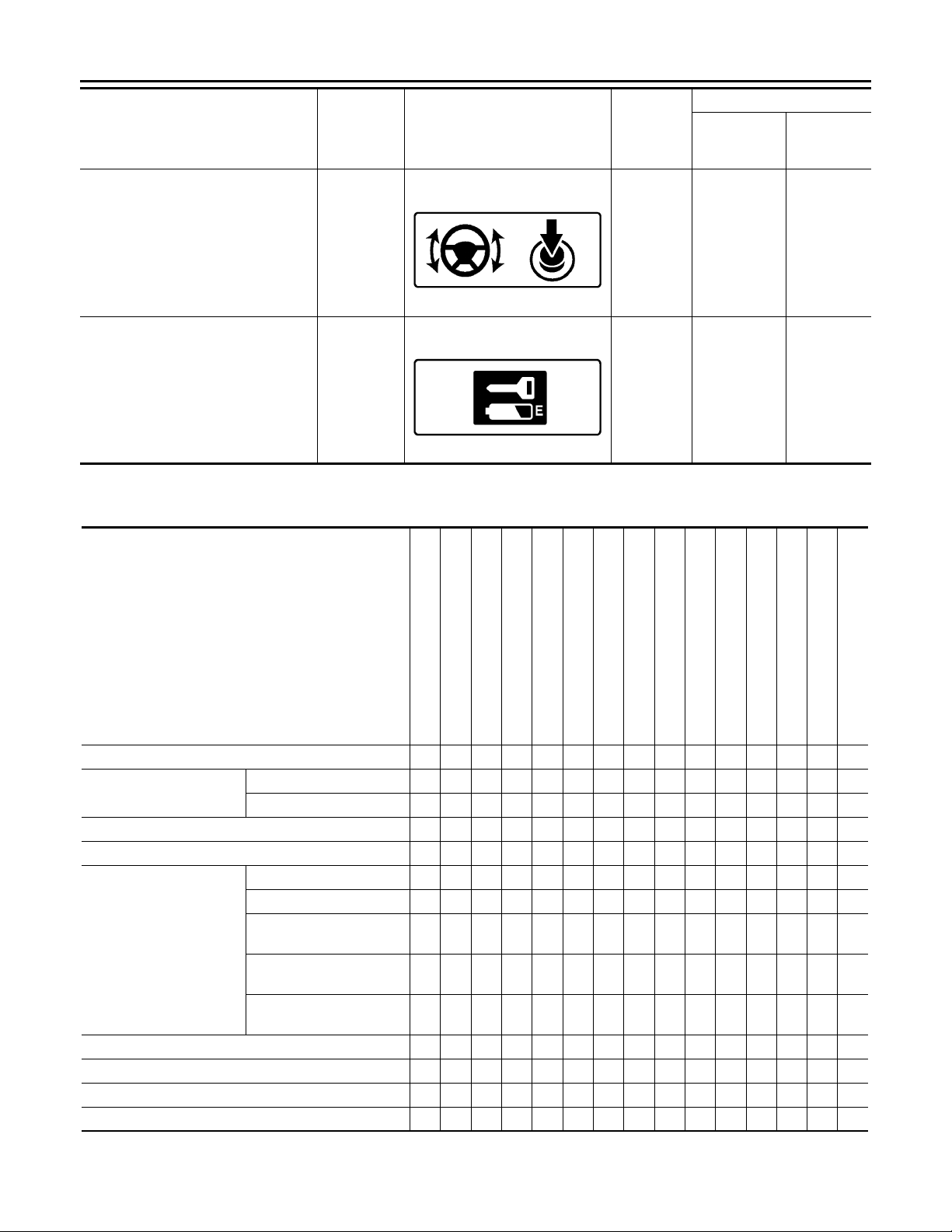
WARNING FUNCTION
B
B
Revision: October 2006
2007 G35 Sedan
< FUNCTION DIAGNOSIS >
Warning/Information functions
Steering lock information — — — —
Intelligent Key low battery warning — — — —
“KEY” warn-
ing lamp
Combination meter display
JMKIA0033G
JMKIA0048G
LIST OF OPERATION RELATED PARTS
Parts marked with × are the parts related to operation.
[INTELLIGENT KEY SYSTEM]
Warning chime
Key slot illumination
Combination
meter buzzer
Intelligent
Key warning
buzzer
Warning function
Intelligent Key
Key slot
Ignition switch
Door switch
Door request switch
Inside key antenna
Outside key antenna
Intelligent Key warning buzzer
Combination meter warning buzzer
CAN communication system
BCM
Combination meter display
Key slot illumination
Park position switch
“KEY” warning lamp
Intelligent Key system malfunction ×× ×
OFF position warning
P position warning × ×××× ×
ACC warning × ×××× ×
Take away warning
Door lock operation warning ×× ЧЧЧЧЧ ××
Key ID warning ××× × ×××
Key warning ×× × ЧЧЧЧЧ
Intelligent Key insert information ×××× × ××××
For internal × ×××
For external ××××
Door is open or close × × × ЧЧЧЧЧЧ
Door is open ××× ××××
Push-ignition switch oper-
ation
Take away through win-
dow
Intelligent Key is removed
from key slot
× × × ЧЧЧЧЧ
× × ЧЧЧЧЧ
×× × ××××
DLK-40
Page 41

< FUNCTION DIAGNOSIS >
Revision: October 2006
2007 G35 Sedan
WARNING FUNCTION
[INTELLIGENT KEY SYSTEM]
A
Warning function
Intelligent Key
Key slot
Ignition switch
Door switch
Door request switch
Inside key antenna
Outside key antenna
Intelligent Key warning buzzer
Combination meter warning buzzer
CAN communication system
BCM
Combination meter display
Key slot illumination
Park position switch
Ignition switch is ON posi-
Engine start information
Steering lock information × ×××
Intelligent Key low battery warning × × ×××
tion
Ignition switch is except
ON position
××× × ××× ×
××× × ×××
Component Parts Location INFOID:0000000000961112
“KEY” warning lamp
B
C
D
E
F
G
H
I
J
DLK
L
M
N
O
P
DLK-41
Page 42
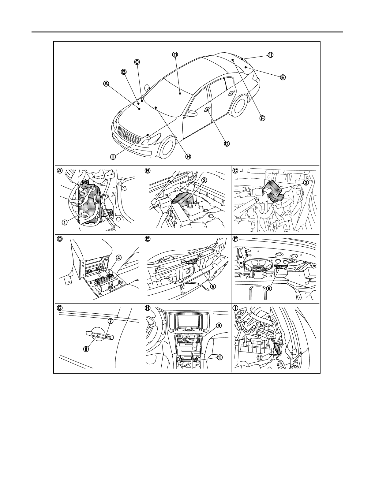
< FUNCTION DIAGNOSIS >
B
Revision: October 2006
2007 G35 Sedan
WARNING FUNCTION
[INTELLIGENT KEY SYSTEM]
1. BCM
M118,M119,M120,M121,M122,M123
4. Inside key antenna (console) M146 5. Outside key antenna (rear bumper)
7. Front outside handle LH (request switch)
D13
10. Inside key antenna (instrument center)
M131
A. Dash side lower (Passenger side). B. Engine room dash panel (RH). C. View with instrument assist lower
JMKIA0142G
2. IPDM E/R E5,E6 3. Remote keyless entry receiver
M104
6. Inside key antenna (trunk room)
B63
8. Front outside handle LH (outside key
antenna) D14
11. Trunk lid request switch B304 12. Intelligent Key warning buzzer (en-
B49
9. Unified meter and A/C AMP
M66,M67
gine room) E57
panel removed.
DLK-42
Page 43
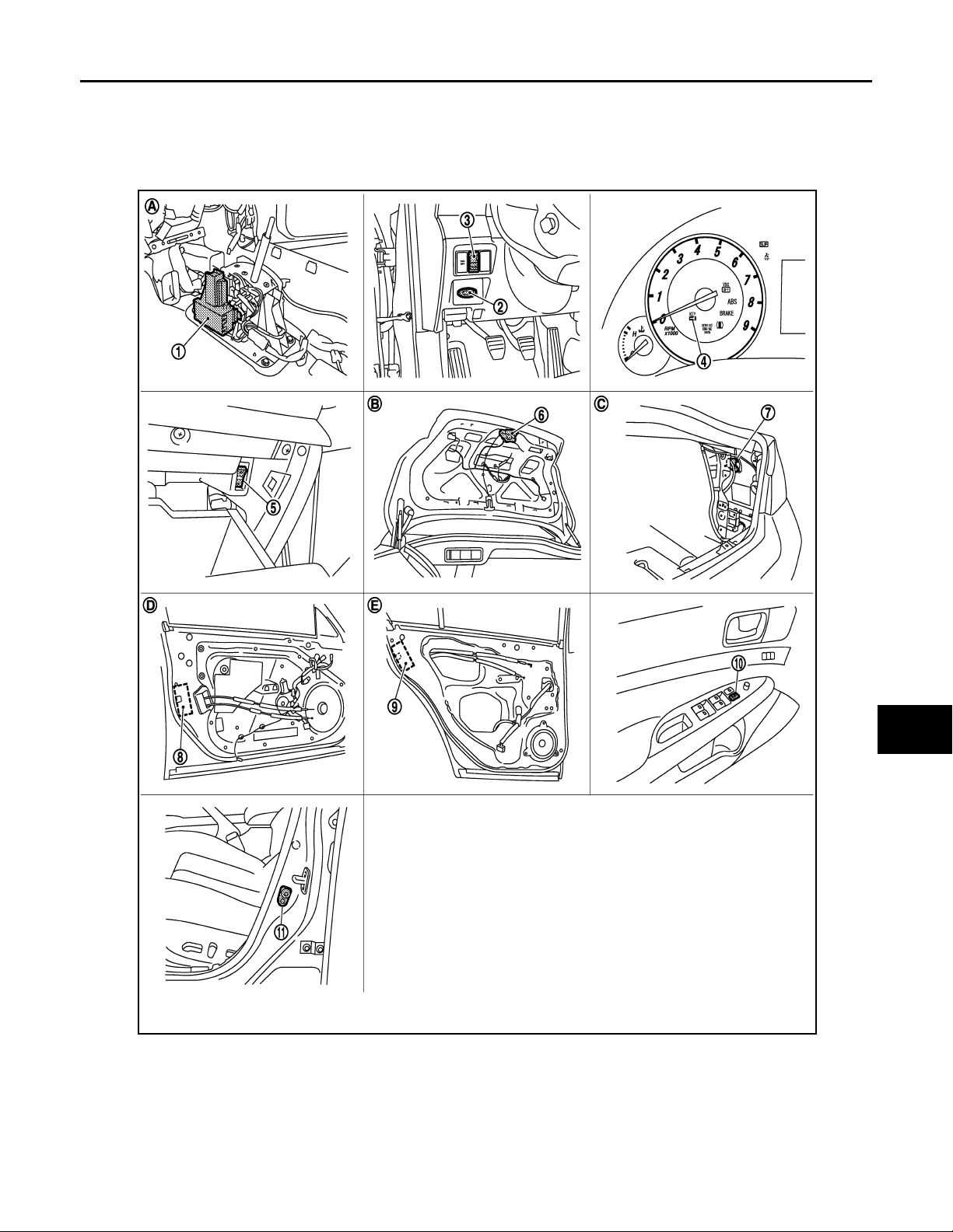
WARNING FUNCTION
B
Revision: October 2006
2007 G35 Sedan
< FUNCTION DIAGNOSIS >
D. View with console rear finisher removed. E. View wit h rear bumper removed. F. View with trunk rear finisher (up-
G. View of front door LH. H. Behind cluster lid C. I. View with hood seal assembly re-
[INTELLIGENT KEY SYSTEM]
per) removed.
moved.
A
B
C
D
E
F
G
H
I
J
DLK
L
M
N
O
1. A/T device (detention switch) 2. Key slot M22 3. Trunk lid opener switch M20
4. Combination meter (Key warning lamp)
M53
7. Fuel lid opener actuator B242 8. Front door lock assembly (driver side) D15 9. Rear door lock assembly D55
10. Power window main switch (door lock unlock switch) D8,D9
JMKIA0143G
P
5. Trunk opener cancel switch M105 6. Trunk lid lock assembly (trunk lid
opener actuator) B303
11. Front door switch B16
DLK-43
Page 44

WARNING FUNCTION
Revision: October 2006
2007 G35 Sedan
< FUNCTION DIAGNOSIS >
A. View with center console assembly re-
moved.
D View with front door finisher removed. E View with rear door finisher removed.
B. View with trunk lid finisher removed. C. View with trunk side finisher re-
[INTELLIGENT KEY SYSTEM]
moved.
DLK-44
Page 45

< FUNCTION DIAGNOSIS >
Revision: October 2006
2007 G35 Sedan
KEY REMINDER FUNCTION
[INTELLIGENT KEY SYSTEM]
KEY REMINDER FUNCTION
System Description INFOID:0000000000961113
Key reminder is the function that prevents the key from being left in the vehicle.
Key reminder has the following 3 functions.
Key remainder function Operation condition O pe rat ion
Right after driver side door is closed under the following conditions
Driver door closed*
Door is open or closed
Trunk is closed
*:If the door closing impact shocks the door lock knob, or contacts against baggage with the door lock knob might activate the door locks
accidentally but unlock operation will be perform in these cases.
• Door lock operation is performed
• Driver side door is opened
• Driver side door is in unlock state
Right after all doors are closed under the following conditions
• Intelligent Key is inside the vehicle
• Any door is opened
• All doors are locked by door lock and unlock switch or door lock knob
Right after trunk is closed under the following conditions
• Intelligent Key is inside trunk room
• All doors are closed
• All doors are locked
CAUTION:
• The above function operates when the Intelligent Key is inside the vehicle. However, there may be
times when the Intelligent Key cannot be detected, and this function will not operate when the Intelligent Key is on the instrument panel, rear parcel shelf, or in the glove box. Also, this system sometimes does not operate if the Intelligent Key is in the door pocket for the open door.
• When the key reminder function is operated when the trunk is open/closed and the buzzers sound, if
the following operations are performed, the key reminder function is cleared and buzzer sounds are
stopped.
- Remote controller door lock button operation of Intelligent Key
- Remote controller door unlock button operation of Intelligent Key
- When the trunk is closed, the Intelligent Key is not inside the vehicle
- When any doo r is open
All doors unlock
• All doors unlock
• Honk Intelligent Key warning
buzzer
• Trunk open
• Honk Intelligent Key warning
buzzer
A
B
C
D
E
F
G
H
I
J
Component Parts Location INFOID:0000000000961114
DLK
L
M
N
O
P
DLK-45
Page 46
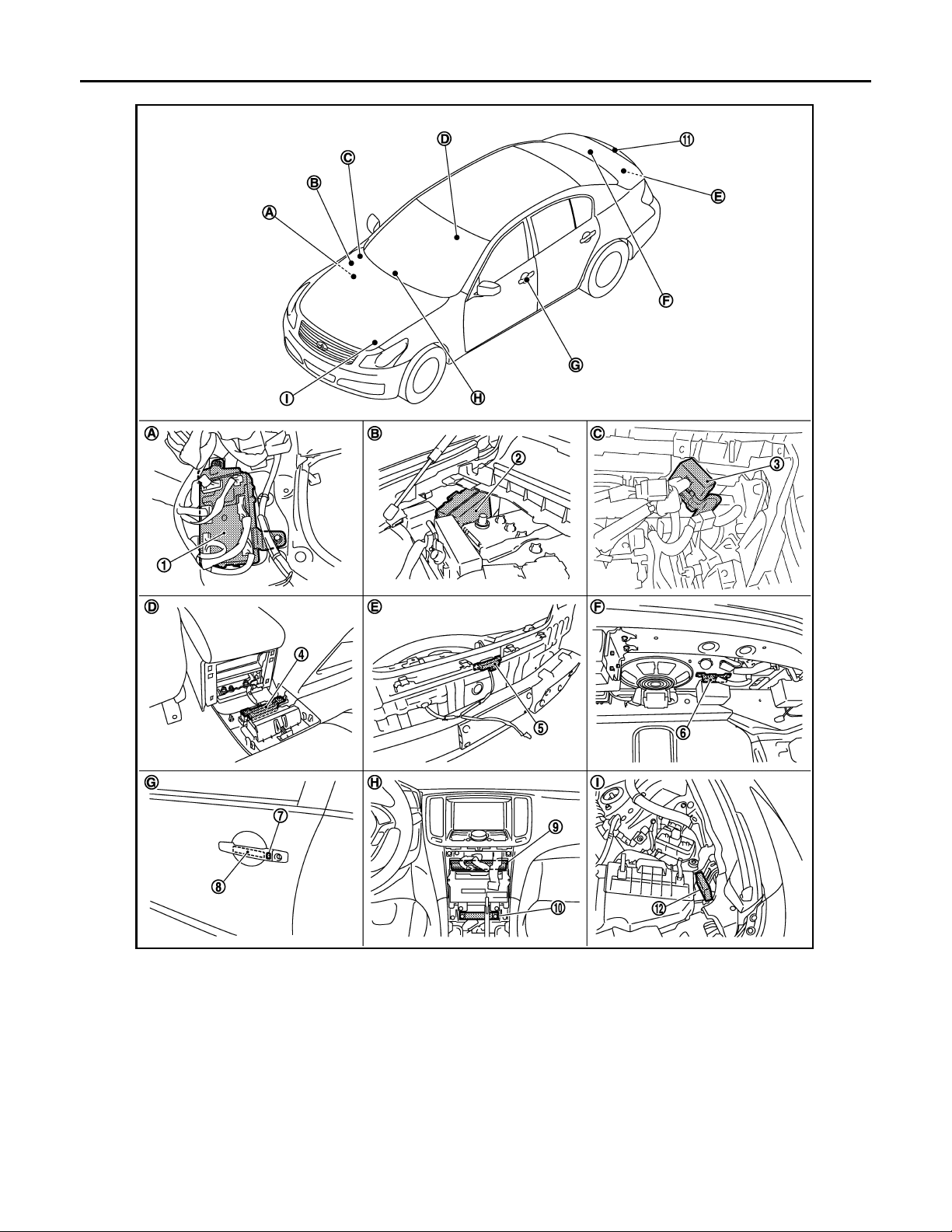
< FUNCTION DIAGNOSIS >
B
Revision: October 2006
2007 G35 Sedan
KEY REMINDER FUNCTION
[INTELLIGENT KEY SYSTEM]
1. BCM
M118,M119,M120,M121,M122,M123
4. Inside key antenna (console) M146 5. Outside key antenna (rear bumper)
7. Front outside handle LH (request switch)
D13
10. Inside key antenna (instrument center)
M131
A. Dash side lower (Passenger side). B. Engine room dash panel (RH). C. View with instrument assist lower
JMKIA0142G
2. IPDM E/R E5,E6 3. Remote keyless entry receiver
M104
6. Inside key antenna (trunk room)
B63
8. Front outside handle LH (outside key
antenna) D14
11. Trunk lid request switch B304 12. Intelligent Key warning buzzer (en-
B49
9. Unified meter and A/C AMP
M66,M67
gine room) E57
panel removed.
DLK-46
Page 47
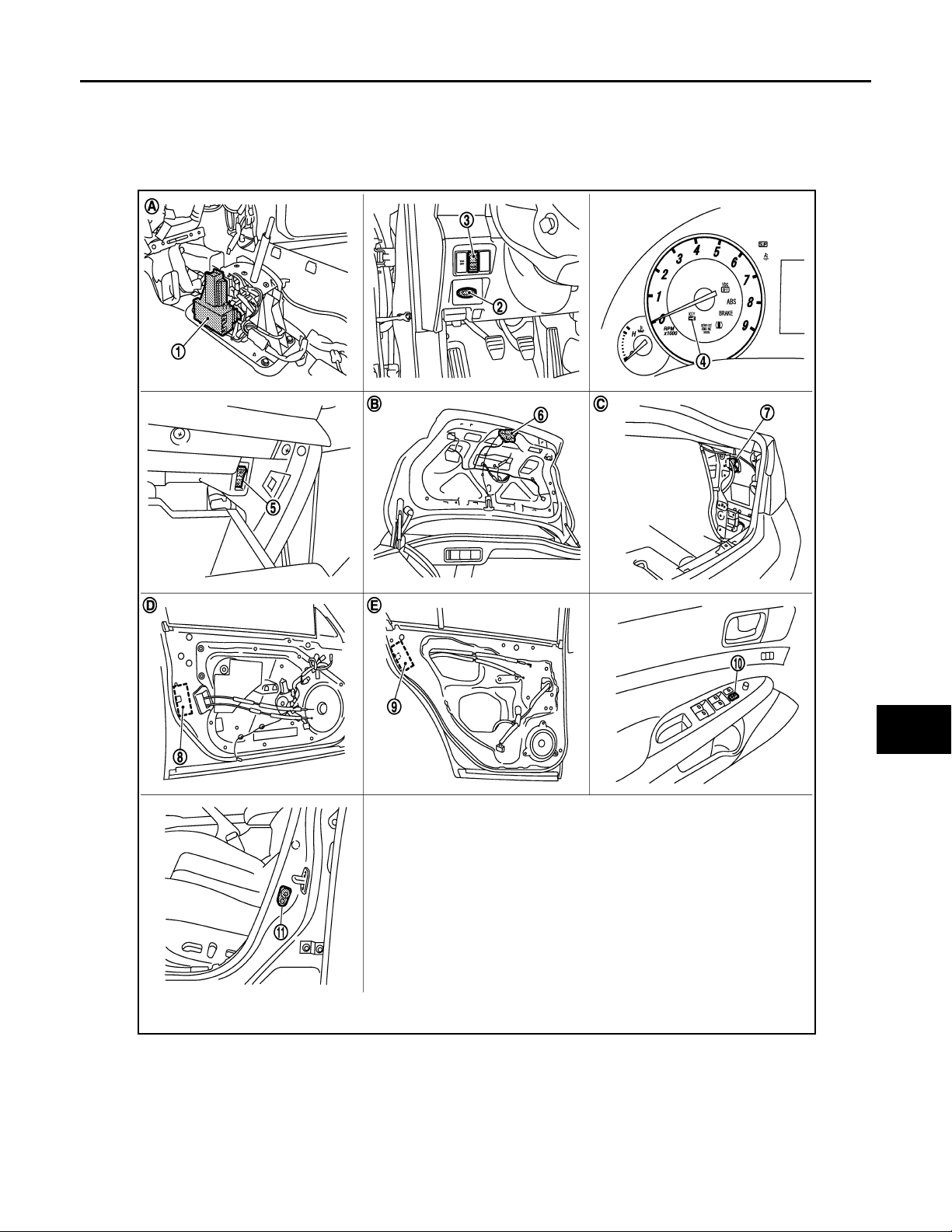
KEY REMINDER FUNCTION
B
Revision: October 2006
2007 G35 Sedan
< FUNCTION DIAGNOSIS >
D. View with console rear finisher removed. E. View wit h rear bumper removed. F. View with trunk rear finisher (up-
G. View of front door LH. H. Behind cluster lid C. I. View with hood seal assembly re-
[INTELLIGENT KEY SYSTEM]
per) removed.
moved.
A
B
C
D
E
F
G
H
I
J
DLK
L
M
N
O
1. A/T device (detention switch) 2. Key slot M22 3. Trunk lid opener switch M20
4. Combination meter (Key warning lamp)
M53
7. Fuel lid opener actuator B242 8. Front door lock assembly (driver side) D15 9. Rear door lock assembly D55
10. Power window main switch (door lock unlock switch) D8,D9
JMKIA0143G
P
5. Trunk opener cancel switch M105 6. Trunk lid lock assembly (trunk lid
opener actuator) B303
11. Front door switch B16
DLK-47
Page 48

KEY REMINDER FUNCTION
Revision: October 2006
2007 G35 Sedan
< FUNCTION DIAGNOSIS >
A. View with center console assembly re-
moved.
D View with front door finisher removed. E View with rear door finisher removed.
B. View with trunk lid finisher removed. C. View with trunk side finisher re-
[INTELLIGENT KEY SYSTEM]
moved.
DLK-48
Page 49

INTEGRATED HOMELINK TRANSMITTER
Revision: October 2006
2007 G35 Sedan
< FUNCTION DIAGNOSIS >
[INTELLIGENT KEY SYSTEM]
INTEGRATED HOMELINK TRANSMITTER
Component Description INFOID:0000000000961115
Item Function
Homelink universal transceiv er A maximum of 3 radio signals can be stored and transmitted to operate the garage door, etc.
A
B
C
D
E
F
G
H
I
J
DLK
L
M
N
O
P
DLK-49
Page 50

DIAGNOSIS SYSTEM (BCM)
Revision: October 2006
2007 G35 Sedan
< FUNCTION DIAGNOSIS >
[INTELLIGENT KEY SYSTEM]
DIAGNOSIS SYSTEM (BCM)
COMMON ITEM
COMMON ITEM : CONSULT-III Function (BCM - COMMON ITEM) INFOID:0000000000961116
APPLICATION ITEM
CONSULT-III performs the following functions via CAN communication with BCM.
Diagnosis mode Function Description
WORK SUPPORT Changes the setting for each system function.
SELF-DIAG RESULTS Displays the diagnosis results judged by BCM. Refer to BCS-74, "
CAN DIAG SUPPORT MNTR Monitors the reception status of CAN communication viewed from BCM.
DATA MONITOR The BCM input/output signals are displayed.
ACTIVE TEST The signals used to activate each device are forcibly supplied from BCM.
ECU IDENTIFICATION The BCM part number is displayed.
CONFIGURATION This function is not used even though it is displayed.
SYSTEM APPLICATION
BCM can perform the following functions for each system.
NOTE:
It can perform the diagnosis modes except the following for all sub system selection items.
DTC Index".
System Sub system selection item
Door lock DOOR LOCK ×××
Rear window defogger REAR DEFOGGER ××
Warning chime BUZZER ××
Interior room lamp timer INT LAMP ×××
Exterior lamp HEAD LAMP ×××
Wiper and washer WIPER ×××
Turn signal and haza rd warning lamp s FLASHER ×××
Air conditioner* AIR CONDITONER ×
Intelligent Key system INTELLIGENT KEY ×××
Combination switch COMB SW ×
BCM BCM ×
IVIS - NATS IMMU ××
Interior room lamp battery saver BATTERY SAVER ×××
Trunk open TRUNK ×
Vehicle security system THEFT ALM ×××
RAP system RETAINED PWR ×
Signal buffer system SIGNAL BUFFER ××
TPMS
*: This item is displayed, but is not used.
TPMS (AIR PRESSURE MONITOR)
WORK SUPPORT DATA MONITOR ACTIVE TEST
×××
Diagnosis mode
DOOR LOCK
DOOR LOCK : CONSULT-III Function (BCM - DOOR LOCK) INFOID:0000000000961117
BCM CONSULT-III FUNCTION
CONSULT-III performs the following functions via CAN communication with BCM.
DLK-50
Page 51

< FUNCTION DIAGNOSIS >
Revision: October 2006
2007 G35 Sedan
DIAGNOSIS SYSTEM (BCM)
[INTELLIGENT KEY SYSTEM]
Diagnosis mode Function Description
WORK SUPPORT Changes the settin g for ea ch system function.
DATA MONITOR The BCM input/output signals are displayed.
ACTIVE TEST The signals used to activate each device are forcibly supplied from BCM.
WORK SUPPORT
Monitor item Description
DOOR LOCK-UNLOCK SET
D/LOCK VHCL SPD AJT
Selective unlock function mode can be changed to operate (WITH) or not operate (WITHOUT) with
this mode.
Lock with speed customize function mode can be changed to operate (WITH) or not operate
(WITHOUT) with this mode.
DATA MIONITOR
Monitor Item Contents
REQ SW-DR Indicated [ON/OFF] condition of door request switch (driver si de).
REQ SW-AS Indicated [ON/OFF] condition of door request switch (passenger side).
REQ SW-BD/TR Indicated [ON/OFF] condition of trun k op ene r requ es t sw itc h.
DOOR SW-DR Indicated [ON/OFF] condition of front door switch (driver side).
DOOR SW-AS Indicated [ON/OFF] condition of front door switch (passenger side).
DOOR SW-RR Indicated [ON/OFF] condition of rear door switch RH.
DOOR SW-RL Indicated [ON/OFF] condition of rear door switch LH.
DOOR SW-BK
CDL LOCK SW Indicated [ON/OFF] condition of lock signal from door lock unlock switch.
CDL UNLOCK SW Indicated [ON/OFF] condition of unlock signal from door lock unlock switch.
KEY CYL LK-SW Indicated [ON/OFF] condition of lock signal from key cylinder.
KEY CYL UN-SW Indicated [ON/OFF] condition of unlock signal from key cylinder.
NOTE:
This item is displayed, but cannot be monitored.
ACTIVE TEST
A
B
C
D
E
F
G
H
I
J
DLK
DOOR LOCK
INTELLIGENT KEY
INTELLIGENT KEY : CONSULT-III Function (BCM - INTELLIGENT KEY) INFOID:0000000000961118
BCM CONSULT-III FUNCTION
CONSULT-III performs the following functions via CAN communication with BCM.
Diagnosis mode Function Description
WORK SUPPORT Changes the settin g for ea ch system function.
SELF-DIAG RESULTS Displays the diagnosis results judged by BCM.
Test item Description
This test is able to check door lock/unlock operation.
• The all door lock actuators are locked when “LOCK” on CONSULT-III screen is touched.
• The all door lock actuators are unlocked when “ALL UNLK” on CONSULT-III screen is touched.
• The door lock actuator (driver side) is unlocked when “DR UNLK” on CONSULT-III screen is
touched.
• The door lock actuator (passenger side) is unlocked when “AS UNLK” on CONSULT- III screen
is touched.
• The door lock actuator (other) is unlocked when “OTR ULK” on CONSULT-III screen is touched.
DLK-51
L
M
N
O
P
Page 52

DIAGNOSIS SYSTEM (BCM)
Revision: October 2006
2007 G35 Sedan
< FUNCTION DIAGNOSIS >
Diagnosis mode Function Description
DATA MONITOR The BCM input/output signals are displayed.
ACTIVE TEST The signals used to activate each device are forcibly supplied from BCM.
WORK SUPPORT
Monitor item Description
REMO CONT ID CONFIR It can be checked whether Intelligent Key ID code is registered or not in this mode.
LOCK/UNLOCK BY I-KEY
ENGINE START BY I-KEY Engine start function mode can be changed to operate (ON) or not operate (OFF) with this mode.
TRUNK/GLASS HATCH OPEN
PANIC ALARM SET
PW DOWN SET
TRUNK OPEN DELAY
LO- BATT OF KEY FOB WARN
ANTI KEY LOCK IN FUNCTI Key reminder function mode can be changed to operate (ON) or not operate (OFF) with this mode.
HORN WITH KEYLESS LOCK
HAZARD ANSWER BACK
ANS BACK I-KEY LOCK
ANS BACK I-KEY UNLOCK
SHORT CRANKING OUTPUT
INSIDE ANT DIAGNOSIS This function allows inside key antenna self-diagnosis.
Door lock/unlock function by door request switch (driver side, passenger side and trunk) mode can
be changed to operate (ON) or not operate (OFF) in this mode.
Buzzer reminder function mode by trun k opener request switch can be changed to operate (ON)
or not operate (OFF) with this mode.
Panic alarm button pressing time on Intelligent Key remote control button can be selected from the
following with this mode.
• 0.5 sec.
• 1.5 sec.
• OFF: Non-operation
Unlock button pressing time on Intelligent Key button can be selected from the following with this
mode.
• 3 sec.
• 5 sec.
• OFF: Non-operation
Trunk button pressing time on Intelligent Key button can be selected from the following with this
mode.
• 0.5 sec.
• 1.5 sec.
• OFF: Non-operation
Intelligent Key low battery warning mode can be changed to operate (ON) or not operate (OFF)
with this mode.
Horn reminder function mode by Intellig ent Key butt on can be chan ged to oper ate (ON) or not operate (OFF) with this mode.
Hazard reminder function mode can be selected from the following with this mode.
• LOCK ONLY: Door lock operation only
• UNLOCK ONLY : Door unlock operation only
• LOCK AND UNLOCK: Lock/unlock operation
• OFF: Non operation
Buzzer reminder function (lock op eration) mode by door request switch (driver side and p assenger
side) can be selected from the following with this mode.
• HORN CHIRP: Sound horn
• BUZZER: Sound Intelligent Key warning buzzer
• OFF: Non-operation
Buzzer reminder function (unlock ope ration) mode by door request switch can be changed to op-
erate (ON) or not operate (OFF) with this mode.
Starter motor can operate during the times below.
• 70 msec
•100 msec
•200 msec
[INTELLIGENT KEY SYSTEM]
SELF-DIAG RESULT
Refer to BCS-74, "DTC Index".
DATA MONITOR
DLK-52
Page 53

< FUNCTION DIAGNOSIS >
Revision: October 2006
2007 G35 Sedan
DIAGNOSIS SYSTEM (BCM)
[INTELLIGENT KEY SYSTEM]
Monitor Item Condition
REQ SW-DR Indicates [ON/OFF] condition of door request switch (driver side).
REQ SW-AS Indicates [ON/OFF] condition of door request switch (passenger side).
REQ SW-BD/TR Indicates [ON/OFF] condition of trunk opener reques t switc h.
PUSH SW Indicates [ON/OFF] condition of push-butto n ign ition switch.
CLUCH SW Indicates [ON/OFF] condition of clutch switch.
BRAKE SW 1 Indicates [ON/OFF] condition of brake switch.
DETE/CANCL SW Indicates [ON/OFF] condition of P position.
SFT PN/N SW Indicates [ON/OFF] condition of P or N position.
S/L -LOCK Indic ate s [ON/OFF] co nd itio n of ste eri ng lock (LOCK).
S/L -UNLOCK Indicates [ON/OFF] condition of steering lock (UNLOCK).
S/L RELAY-F/B Indicates [ON/OFF] condition of ignition switch.
UNLK SEN-DR Ind ic ate s [ON/OFF] co nd itio n of driver door UNLOCK status.
PUSH SW -IPDM Indicates [O N/OFF] co nd itio n of push-button ignition switch.
IGN RLY1 F/B Indicates [ON/OFF] condition of ignition relay 1.
DETE SW -IPDM Indicates [ON/OFF] condition of P position.
SFT PN -IPDM Indicates [ON/OFF] condition of P or N positio n.
SFT P -MET Indicates [ON/OFF] condition of P position.
SFT N -MET Indicates [ON/OFF] condition of N position.
ENGINE STATE Indicates [STOP/START/CRANK/RUN] condition of engine states.
S/L LOCK-IPDM Indicates [ON/OFF] cond itio n of ste eri ng lock (LOCK).
S/L UNLOCK-IPDM Indicates [ON/OFF] condition of steering lock (UNLOCK).
S/L RELAY-REQ Indicate s [ON/OFF] co nd itio n of ste eri ng lock relay.
VEH SPEED 1 Display the vehicle speed signal received from combination meter by numerical value [Km/h].
VEH SPEED 2 Display the vehicle speed signal received from ABS or VDC or CVT by numerical value [Km/h].
DOOR STAT-DR Indicates [LOCK/READY/UNLK] condition of driver side door status.
DOOR STAT-AS Indicates [LOCK/READY/UNLK] condition of passenger side door status.
KEY SW -SLOT Indicates [ON/OFF] condition of key slot.
RKE OPE COUN1
RKE OPE COUN2
TRNK/HAT MNTR Indicates [ON/OFF] condition of trunk lid.
RKE-LOCK Indicates [ON/OFF] condition of LOCK signal from Intelligent Key.
RKE-UNLOCK Indicates [ON/OFF] cond itio n of UNLOCK signal from Intelligent Key.
RKE-TR/BD Indicates [ON/OFF] condition of TRUNK OPEN signal from Intelligent Key.
RKE-PANIC Indicate s [ON/OFF] co nd itio n of PANIC button of Intelligent Key.
RKE-P/W OPEN Indicates [ON/OFF] condition of P/W DOWN signal from Intelligent Key.
RKE-MODE CHG Indicates [ON/OFF] condition of MODE CHANGE signal from Intelligent Key.
When remote keyless entry receiver receives the signal transmitted while operating on Intelligent Key, the
numerical value start changing.
NOTE:
This item is displayed, but cannot be monitored.
A
B
C
D
E
F
G
H
I
J
DLK
L
M
N
O
ACTIVE TEST
BATTERY SAVER
PW REMOTO DOWN SET
P
Test item Description
This test is able to check interior room lamp operation.
The interior room lamp will be activated after “ON” on CONSULT-III screen is touched.
This test is able to check power window down operation.
The power window down will be activated after “ON” on CONSULT-III screen is touched.
DLK-53
Page 54

< FUNCTION DIAGNOSIS >
Revision: October 2006
2007 G35 Sedan
Test item Description
OUTSIDE BUZZER
INSIDE BUZZER
INDICATOR
INT LAMP
LCD
TRUNK/GLASS HATCH
FLASHER
HORN
IGN CONT2
P RANGE
ENGINE SW ILLUMI
LOCK INDCATOR
ACC INDCATOR
IGNITION ON IND
KEY SLOT ILLUMI
DIAGNOSIS SYSTEM (BCM)
[INTELLIGENT KEY SYSTEM]
This test is able to check Intelligent Key warning buzzer operation.
Intelligent Key warning buzzer sounds when “ON” on CONSULT-III screen is touched.
This test is able to check warning chime in combination meter operation.
• Take away warning chime sounds when “TAKE OUT” on CONSULT-III screen is touched.
• Key warning chime sounds when “KEY WARN” on CONSULT-III screen is touched.
• P position warning chime sounds when “P RNG WARN” on CONSULT-III screen is touched.
• ACC warning chime sounds when “ACC WARN” on CONSULT-III screen is touched.
This test is able to check warning lamp operation.
• “KEY” Warning lamp illuminates when “KEY IND ON” on CONSULT-III screen is touched.
• “KEY” Warning lamp flashes when “KEY IND FSH” on CONSULT-III screen is touched.
This test is able to check in terior room lamp operation.
The interior room lamp will be activated after “ON” on CONSULT-III screen is touched.
This test is able to check meter display information
• Engine start information displays when “BRAKE/P” on CONSULT-III screen is touched.
• Engine start information displays when “BRAKE/P/ON” on CONSULT-III screen is touched.
• Key ID warning displays when “KEY ID NG” on CONSULT-III screen is touched.
• Steering lock information displays when “STLCK RELES” on CONSULT-III screen is touched.
• P position warning displays when “P RNG IND” on CONSULT-III screen is to uched.
• Intelligent Key insert information displays when “INSERT KEY” on CONSULT-III screen is
touched.
• Intelligent Key low battery warning displays when “KEY BAT LOW” on CONSULT-III screen is
touched.
• Take away through window warning displays when “TK AWAY WDW” on CONSULT-III screen
is touched.
• Take away warning display when “TAKE AWAY” on CONSULT-III screen is touched.
• OFF position warning display when “IGN OFF WARN” on CONSULT-III screen is touched.
This test is able to check trunk lid opener actuator open operation.
This actuator opens when “ON” on CONSULT-III screen is touched.
This test is able to check security hazard la mp operation.
The hazard lamps will be activated after “ON” on CONSULT-III screen is touched.
This test is able to check horn operation.
The horn will be activated after “ON” on CONSULT-III screen is touched.
This test is able to check security hazard la mp operation.
The hazard lamps will be activated after “ON” on CONSULT-III screen is touched.
This test is able to check A/T device power supply
A/T device power is supplied when “ON” on CONSULT-III screen is touched.
This test is able to check push-ignition switch illumination operation.
Push-ignition switch illumination illuminates when “ON” on CONSULT-III screen is touched.
This test is able to check LOCK indicator in push-ignition switch operation.
LOCK indicator in push-ignition switch illuminates when “ON” on CONSULT-III screen is touched.
This test is able to check ACC indicator in push -ignition switch operation.
LOCK indicator in push-ignition switch illuminates when “ON” on CONSULT-III screen is touched.
This test is able to check INGITION ON indicator in push-ignition switch operation.
LOCK indicator in push-ignition switch illuminates when “ON” on CONSULT-III screen is touched.
This test is able to check key slot illumination operation.
Key slot illumination flash when “ON” on CONSULT-III screen is touched.
TRUNK
TRUNK : CONSULT-III Function (BCM - TRUNK) INFOID:0000000000961119
BCM CONSULT-III FUNCTION
CONSULT-III performs the following functions via CAN communication with BCM.
Diagnosis mode Function Description
DATA MONITOR The BCM input/output signals are displayed.
ACTIVE TEST The signals used to activate each device are forcibly supplied from BCM.
DLK-54
Page 55

DIAGNOSIS SYSTEM (BCM)
Revision: October 2006
2007 G35 Sedan
< FUNCTION DIAGNOSIS >
DATA MONITOR
Monitor Item Contents
PUSH SW Indicates [ON/OFF] condition of push switch.
UNLK SEN -DR Indicates [ON/OFF] condition of unlock sensor.
VEH SPEED 1 Indicates [Km/h] condition of vehicle speed signal from combination meter.
KEY CYL SW-TR
TR CANCEL SW Indicates [ON/OFF] condition of trunk lid opener cancel switch.
TR/BD OPEN SW Indicates [ON/OFF] condition of trunk lid opener switch.
TRNK/HAT MNTR Indicates [ON/OFF] condition of trunk room lamp switch.
RKE-TR/BD Indicates [ON/OFF] condition of trunk open signal from Intelligent Key remote controller button.
NOTE:
This item is displayed, but cannot be monitored.
ACTIVE TEST
[INTELLIGENT KEY SYSTEM]
A
B
C
D
E
Test item Description
TRUNK/GLASS HATCH
F
This test is able to check trunk open operation.
Trunk open when “OPEN” on CONSULT-III screen is touched.
G
H
I
J
DLK
L
M
N
O
P
DLK-55
Page 56

U1000 CAN COMM CIRCUIT
Revision: October 2006
2007 G35 Sedan
< COMPONENT DIAGNOSIS >
[INTELLIGENT KEY SYSTEM]
COMPONENT DIAGNOSIS
U1000 CAN COMM CIRCUIT
Description INFOID:0000000000961120
CAN (Controller Area Network) is a serial communication line for real time applications. It is an on-vehicle multiplex communication line with high data communication speed and excellent error detection ability. Modern
vehicle is equipped with many electronic control unit, and each control unit shares information and links with
other control units during operation (not independent). In CAN communication, control units are connected
with 2 communication lines (CAN H-line, CAN L-line) allowing a high rate of information transmission with less
wiring. Each control unit transmits/receives data but selectively reads required data only.
CAN Communication Signal Chart. Refer to LAN-28, "
DTC Logic INFOID:0000000000961121
DTC DETECTION LOGIC
CAN Communication Signal Chart".
DTC
U1000 CAN COMM CIRCUIT
CONSULT-III display
description
DTC Detection Condition Possible cause
When BCM cannot communicate CAN communication signal continuously for 2 seconds or more.
In CAN communication system, any item (or items)
of the following listed below is malfunctioning.
•Transmission
• Receiving (ECM)
• Receiving (VDC/TCS/ABS)
• Receiving (METER/M&A)
• Receiving (TCM)
• Receiving (MULTI AV)
• Receiving (IPDM E/R)
Diagnosis Procedure INFOID:0000000000961122
1.PERFORM SELF DIAGNOSTIC
1. Turn ignition switch ON and wait for 2 second or more.
2. Check “Self Diagnostic Result”.
Is
“CAN COMM CIRCUIT” displayed?
YES >> Refer to LAN-18, "Trouble Diagnosis Flow Chart".
NO >> Refer to GI-39, "
Intermittent Incident".
DLK-56
Page 57

< COMPONENT DIAGNOSIS >
Revision: October 2006
2007 G35 Sedan
U1010 CONTROL UNIT (CAN)
[INTELLIGENT KEY SYSTEM]
U1010 CONTROL UNIT (CAN)
DTC Logic INFOID:0000000000961123
DTC DETECTION LOGIC
DTC
U1010 CONTROL UNIT (CAN) BCM detected internal CAN communication circuit malfunction. BCM
CONSULT-III display de-
scription
DTC Detection Condition Possible cause
Diagnosis Procedure INFOID:0000000000961124
1.REPLACE BCM
When DTC [U1010] is detected, replace BCM.
>> Replace BCM.
Special Repair Requirement INFOID:0000000000961125
1.REQUIRED WORK WHEN REPLACING BCM
Initialize IVIS by CONSULT-III. For the details of initialization refer to CONSULT-III operation manual NATSIVIS/NVIS.
>> Work end.
A
B
C
D
E
F
G
H
I
J
DLK
L
M
N
O
P
DLK-57
Page 58
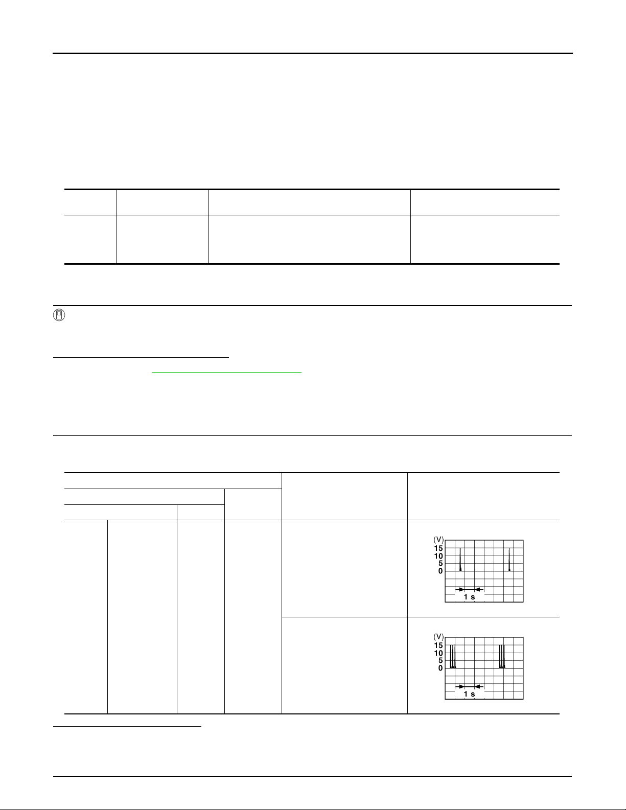
B2621 INSIDE KEY ANTENNA 1
B
B
Revision: October 2006
2007 G35 Sedan
< COMPONENT DIAGNOSIS >
[INTELLIGENT KEY SYSTEM]
B2621 INSIDE KEY ANTENNA 1
Description INFOID:0000000000961126
Detects whether Intelligent Key is inside the vehicle.
Installed in the instrument center.
DTC Logic INFOID:0000000000961127
DTC DETECTION LOGIC
DTC No.
B2621
Trouble diagnosis
name
INSIDE ANTENNA 1
CIRCUIT
DTC detecting condition Possible cause
An excessive high or low volt age from inside antenna is sent to BCM.
• Inside key antenna (instrument
center)
• Between BCM and Inside key antenna (instrument center)
DTC CONFIRMATION PROCEDURE
1.PERFORM DTC CONFIRMATION PROCEDURE
With CONSULT-III
1. Perform inside key antenna (“INSIDE ANT DIAGNOSIS”) on Work Support” of “INTELLIGENT KEY”.
2. Perform “INTELLIGENT KEY” Self Diagnostic Result.
Is inside key antenna DTC detected?
YES >> Refer to DLK-58, "Diagnosis Procedure".
NO >> Inside key antenna (instrument center) is OK.
Diagnosis Procedure INFOID:0000000000961128
1.CHECK INSIDE KEY ANTENNA INPUT SIGNAL 1
1. Turn ignition switch OFF.
2. Check signal between BCM connector and ground with oscilloscope.
Terminals
(+)
BCM connector Terminal
(–)
Condition
Signal
(Reference value.)
M122
Is the inspection result normal?
YES >> Check the condition of harness and connector.
NO >> GO TO 2.
2.CHECK INSIDE KEY ANTENNA CIRCUIT
Instrument cen-
ter
79 Ground
Place Intelligent Key inside the
vehicle.
JMKIA0062G
Place Intelligent Key outside
the vehicle.
JMKIA0063G
DLK-58
Page 59
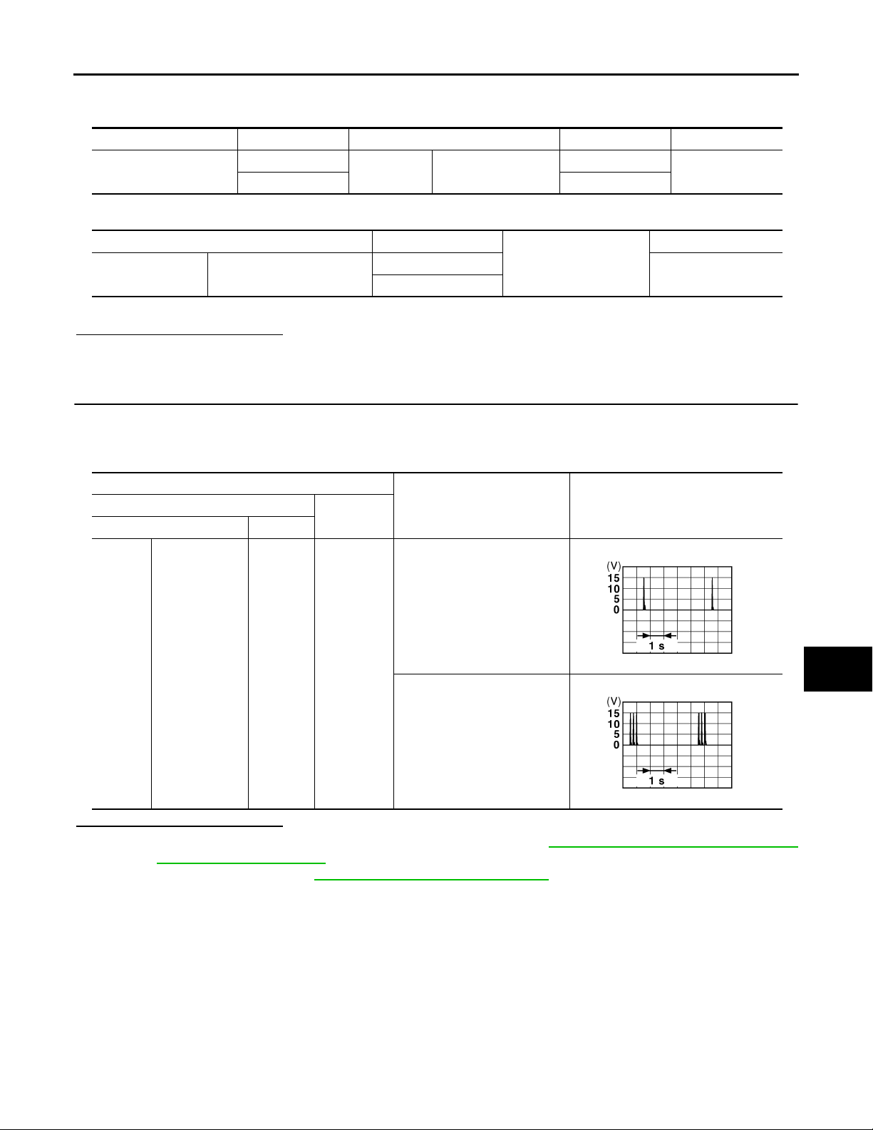
B2621 INSIDE KEY ANTENNA 1
B
B
Revision: October 2006
2007 G35 Sedan
< COMPONENT DIAGNOSIS >
1. Disconnect BCM and inside key antenna connector.
2. Check continuity between BCM connector and inside key antenna connector.
BCM connector Terminal Inside key antenna connector Terminal Continuity
M122
78
79 1
M131 Instrument ce nte r
3. Check continuity between BCM connector and ground.
BCM connector Terminal
M122 Instrument center
78
79
[INTELLIGENT KEY SYSTEM]
Ground
A
2
Existed
B
C
Continuity
Not existed
D
Is the inspection result normal?
YES >> GO TO 3.
NO >> Repair or replace harness between BCM and inside key antenna.
3.CHECK INSIDE KEY ANTENNA INPUT SIGNAL 2
1. Replace inside key antenna (instrument center). (New antenna or other antenna)
2. Connect BCM and inside key antenna (instrument center) connector.
3. Check signal between BCM connector and ground with oscilloscope.
Terminals
(+)
BCM connector Terminal
M122
Instrument cen-
ter
(–)
Place Intelligent Key inside the
vehicle.
79 Ground
Place Intelligent Key outside
the vehicle.
Condition
Signal
(Reference value.)
JMKIA0062G
E
F
G
H
I
J
DLK
L
Is the inspection result normal?
YES >> Replace inside key antenna (instrument center). Refer to DLK-219, "INSTRUMENT CENTER :
NO >> Replace BCM. Refer to BCS-79, "
Removal and Installation".
JMKIA0063G
M
N
Removal and Installation".
O
P
DLK-59
Page 60
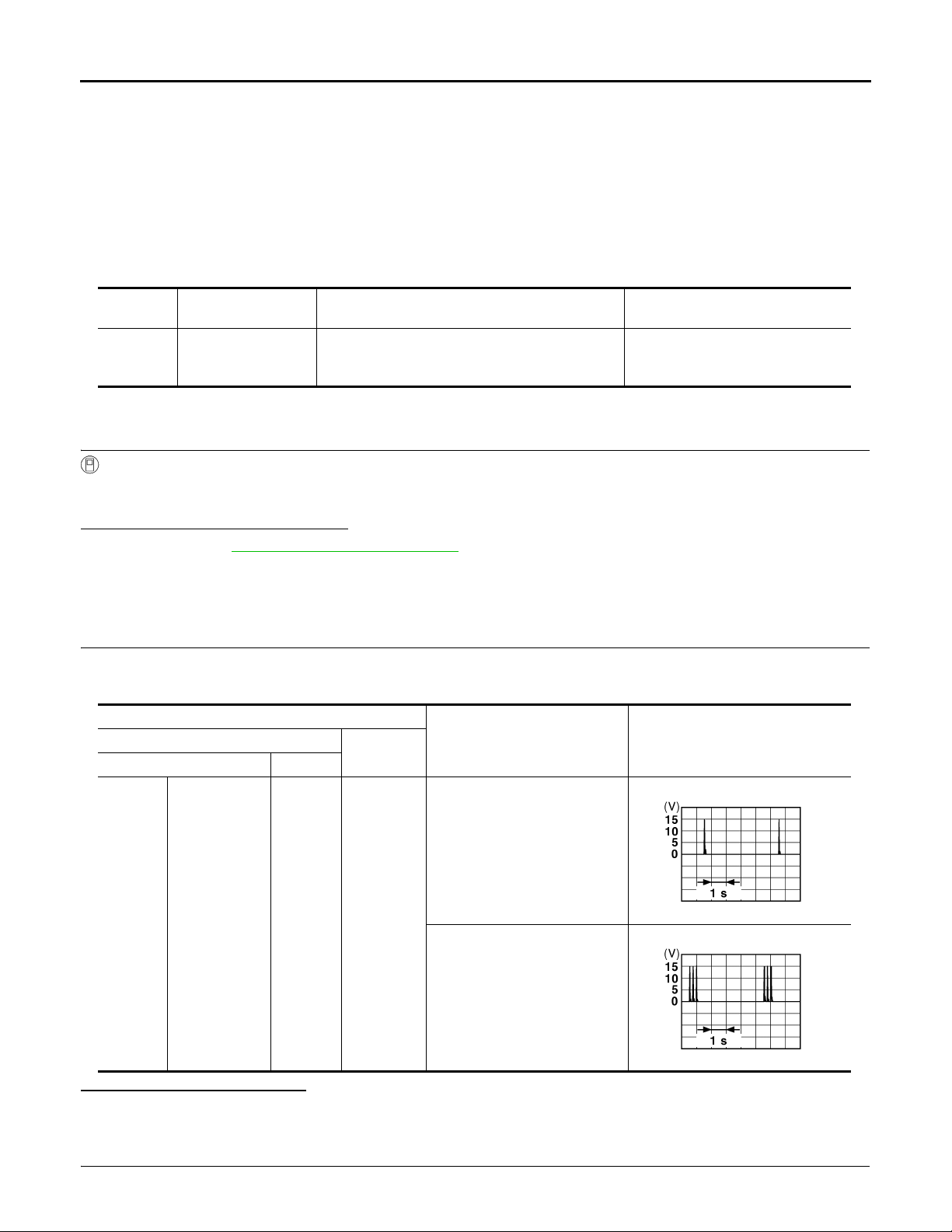
B2622 INSIDE KEY ANTENNA 2
B
B
Revision: October 2006
2007 G35 Sedan
< COMPONENT DIAGNOSIS >
[INTELLIGENT KEY SYSTEM]
B2622 INSIDE KEY ANTENNA 2
Description INFOID:0000000000961129
Detects whether Intelligent Key is inside the vehicle.
Installed in the console.
DTC Logic INFOID:0000000000961130
DTC DETECTION LOGIC
DTC No.
B2622
Trouble diagnosis
name
INSIDE ANTENNA 2
CIRCUIT
DTC detecting condition Possible cause
An excessive high or low volt age from inside antenna is sent to BCM.
• Inside key antenna (console)
• Between BCM 〜Inside key antenna (console)
DTC CONFIRMATION PROCEDURE
1.PERFORM DTC CONFIRMATION PROCEDURE
With CONSULT-III
1. Perform inside key antenna (“INSIDE ANT DIAGNOSIS”) on “Work Support” of “INTELLIGENT KEY”.
2. Perform “INTELLIGENT KEY” Self Diagnostic Result.
Is inside key antenna DTC detected?
YES >> Refer to DLK-60, "Diagnosis Procedure".
NO >> Inside key antenna (console) is OK.
Diagnosis Procedure INFOID:0000000000961131
1.CHECK INSIDE KEY ANTENNA INPUT SIGNAL 1
1. Turn ignition switch OFF.
2. Check signal between BCM connector and ground with oscilloscope.
Terminals
(+)
BCM connector Terminal
(–)
Condition
Signal
(Reference value.)
M122 Console 73 Ground
Is the inspection result normal?
YES >> Check the condition of harness and connector.
NO >> GO TO 2.
2.CHECK INSIDE KEY ANTENNA CIRCUIT
1. Disconnect BCM and inside key antenna (console) connector.
Place Intelligent Key inside the
vehicle.
JMKIA0062G
Place Intelligent Key out side the
vehicle.
JMKIA0063G
DLK-60
Page 61
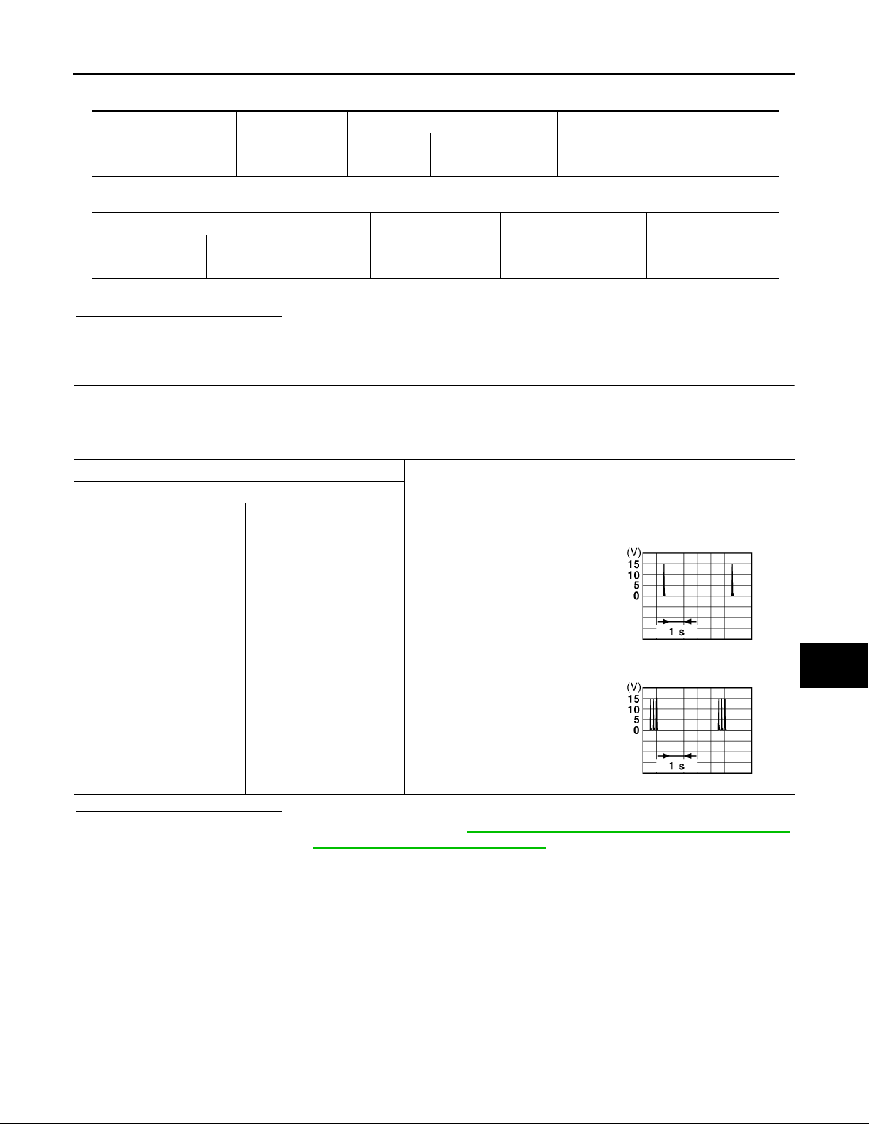
B2622 INSIDE KEY ANTENNA 2
B
B
Revision: October 2006
2007 G35 Sedan
< COMPONENT DIAGNOSIS >
2. Check continuity between BCM connector and inside key antenna connector.
BCM connector Terminal Inside key antenna connector Terminal Continuity
M122
72
73 1
M146 Console
3. Check continuity between BCM connector and ground.
[INTELLIGENT KEY SYSTEM]
A
2
Existed
B
BCM connector Terminal
M122 Console
72
73
Ground
Is the inspection result normal?
YES >> GO TO 3.
NO >> Repair or replace harness between BCM and inside key antenna.
3.CHECK INSIDE KEY ANTENNA INPUT SIGNAL 2
1. Replace inside key antenna (console). (New antenna or other antenna)
2. Connect BCM and inside key antenna (console) connector.
3. Check signal between BCM connector and ground with oscilloscope.
Terminals
(+)
BCM connector Terminal
(–)
Place Intelligent Key inside the vehicle.
Condition
Continuity
Not existed
Signal
(Reference value.)
C
D
E
F
G
H
I
J
M122 Console 73 Ground
Place Intelligent Key outside the
vehicle.
JMKIA0062G
JMKIA0063G
Is the inspection result normal?
YES >> Replace inside key antenna (console). Refer to DLK-219, "CONSOLE : Removal and Installation".
NO >> Replace BCM. Refer to BCS-79, "
Removal and Installation".
DLK
L
M
N
O
P
DLK-61
Page 62
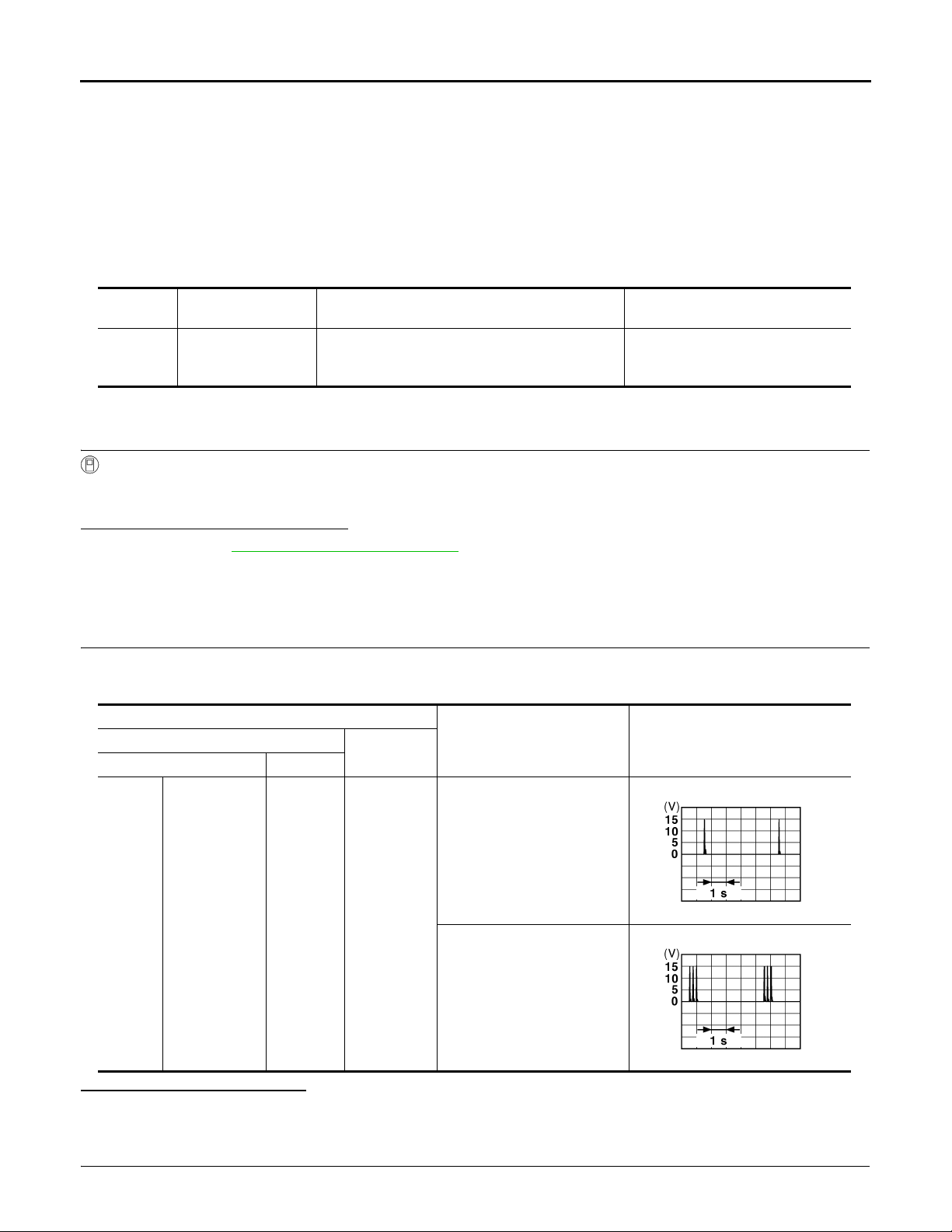
B2623 INSIDE KEY ANTENNA 3
B
B
Revision: October 2006
2007 G35 Sedan
< COMPONENT DIAGNOSIS >
[INTELLIGENT KEY SYSTEM]
B2623 INSIDE KEY ANTENNA 3
Description INFOID:0000000000961132
Detects whether Intelligent Key is inside the vehicle.
Installed in the trunk room.
DTC Logic INFOID:0000000000961133
DTC DETECTION LOGIC
DTC No.
B2623
Trouble diagnosis
name
INSIDE ANTENNA 3
CIRCUIT
DTC detecting condition Possible cause
An excessive high or low volt age from inside antenna is sent to BCM.
• Inside key antenna (trunk room)
• Between BCM 〜Inside key antenna (trunk room)
DTC CONFIRMATION PROCEDURE
1.PERFORM DTC CONFIRMATION PROCEDURE
With CONSULT-III
1. Perform inside key antenna (“INSIDE ANT DIAGNOSIS”) on “Work Support” of “INTELLIGENT KEY”.
2. Perform “INTELLIGENT KEY” Self Diagnostic Result.
Is inside key antenna DTC detected?
YES >> Refer to DLK-62, "Diagnosis Procedure".
NO >> Inside key antenna (trunk room) is OK.
Diagnosis Procedure INFOID:0000000000961134
1.CHECK INSIDE KEY ANTENNA INPUT SIGNAL 1
1. Turn ignition switch OFF.
2. Check signal between BCM connector and ground with oscilloscope.
Terminals
(+)
BCM connector Terminal
(–)
Condition
Signal
(Reference value.)
M121 Trunk room 35 Ground
Is the inspection result normal?
YES >> Check the condition of harness and connector.
NO >> GO TO 2.
2.CHECK INSIDE KEY ANTENNA CIRCUIT
1. Disconnect BCM and inside key antenna (trunk room) connector.
Place Intelligent Key inside the
vehicle.
JMKIA0062G
Place Intelligent Key outside
the vehicle.
JMKIA0063G
DLK-62
Page 63
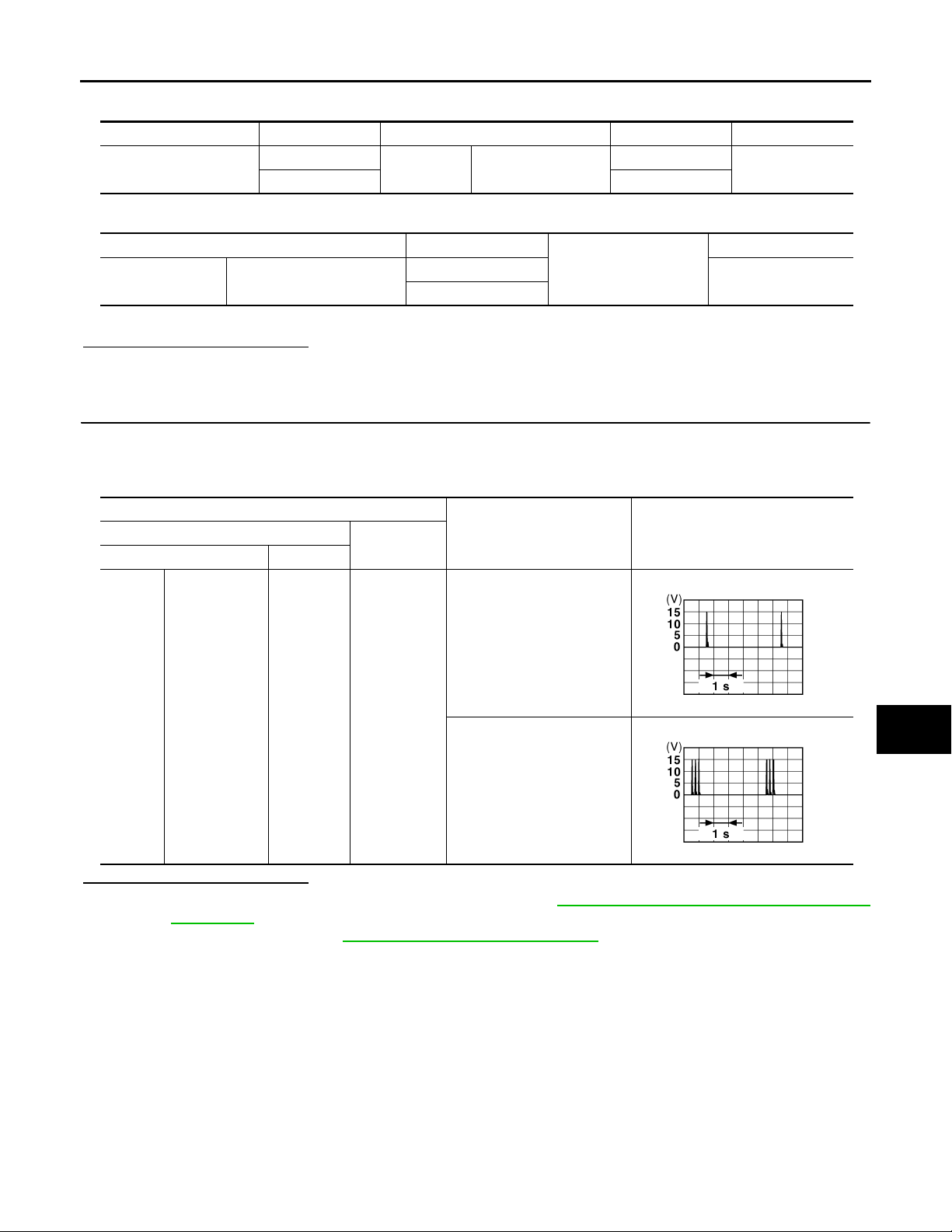
B2623 INSIDE KEY ANTENNA 3
B
B
Revision: October 2006
2007 G35 Sedan
< COMPONENT DIAGNOSIS >
2. Check continuity between BCM connector and inside key antenna (trunk room) connector.
BCM connector Terminal Insid e ke y ant en na connector Terminal Continuity
M121
34
35 1
B49 Trunk room
3. Check continuity between BCM connector and ground.
[INTELLIGENT KEY SYSTEM]
2
Existed
A
B
BCM connector Terminal
M121 Trunk room
34
35
Ground
Is the inspection result normal?
YES >> GO TO 3.
NO >> Repair or replace harness between BCM and inside key antenna (trunk room).
3.CHECK INSIDE KEY ANTENNA INPUT SIGNAL 2
1. Replace inside key antenna (trunk room). (New antenna or other antenna)
2. Connect BCM and inside key antenna (trunk room) connector.
3. Check signal between BCM connector and ground with oscilloscope.
Terminals
(+)
BCM connector Terminal
(–)
Place Intelligent Key inside
the vehicle.
Condition
(Reference value.)
Continuity
Not existed
Signal
C
D
E
F
G
H
I
J
M121 Trunk room 35 Ground
Place Intelligent Key outside
the vehicle.
JMKIA0062G
JMKIA0063G
Is the inspection result normal?
YES >> Replace inside key antenna (trunk room). Refer to DLK-219, "TRUNK ROOM : Removal and
Installation".
NO >> Replace BCM. Refer to BCS-79, "
Removal and Installation".
DLK
L
M
N
O
P
DLK-63
Page 64

POWER SUPPLY AND GROUND CIRCUIT
Revision: October 2006
2007 G35 Sedan
< COMPONENT DIAGNOSIS >
[INTELLIGENT KEY SYSTEM]
POWER SUPPLY AND GROUND CIRCUIT
Diagnosis Procedure INFOID:0000000000961135
1.CHECK FUSE AND FUSIBLE LINK
Check that the following fuse and fusible link are not fusing.
Terminal No. Signal name Fuse and fusible link No.
1
11 10
Battery power supply
K
Is the fuse fusing?
YES >> Replace the blown fuse or fusible link after repairing the affected circuit if a fuse or fusible link is
blown.
NO >> GO TO 2.
2.CHECK POWER SUPPLY CIRCUIT
1. Turn ignition switch OFF.
2. Disconnect BCM connectors.
3. Check voltage between BCM harness connector and ground.
Terminals
(+) (−)
BCM
Connector Terminal
M118 1
M119 11
Is the measurement value normal?
YES >> GO TO 3.
NO >> Repair harness or connector.
3.CHECK GROUND CIRCUIT
Check continuity between BCM harness connector and ground.
BCM
Connector Terminal
M119 13 Existed
Does continuity exist?
YES >> INSPECTION END
NO >> Repair harness or connector.
Ground
Ground
Voltage
(Approx.)
Battery voltage
Continuity
DLK-64
Page 65

< COMPONENT DIAGNOSIS >
Revision: October 2006
2007 G35 Sedan
DOOR SWITCH
[INTELLIGENT KEY SYSTEM]
DOOR SWITCH
Description INFOID:0000000000961136
Detects door open/close condition.
Component Function Check INFOID:0000000000961137
1.CHECK FUNCTION
With CONSULT-III
Check door switches (“DOOR SW-DR”, “DOOR SW -AS”, “DOOR SW-RL” and “DOOR SW-RR”) in Data Monitor” mode with CONSULT-III.
Monitor item Condition
DOOR SW-DR
DOOR SW-AS
DOOR SW-RL
DOOR SW-RR
Is the inspection result normal?
YES >> Door switch is OK.
NO >> Refer to DLK-65, "
Diagnosis Procedure".
Diagnosis Procedure INFOID:0000000000961138
CLOSE → OPEN: OFF → ON
A
B
C
D
E
F
G
H
1.CHECK DOOR SWITCH INPUT SIGNAL
1. Turn ignition switch OFF.
2. Check signal between BCM connector and ground with oscilloscope.
I
J
DLK
L
M
N
O
P
DLK-65
Page 66
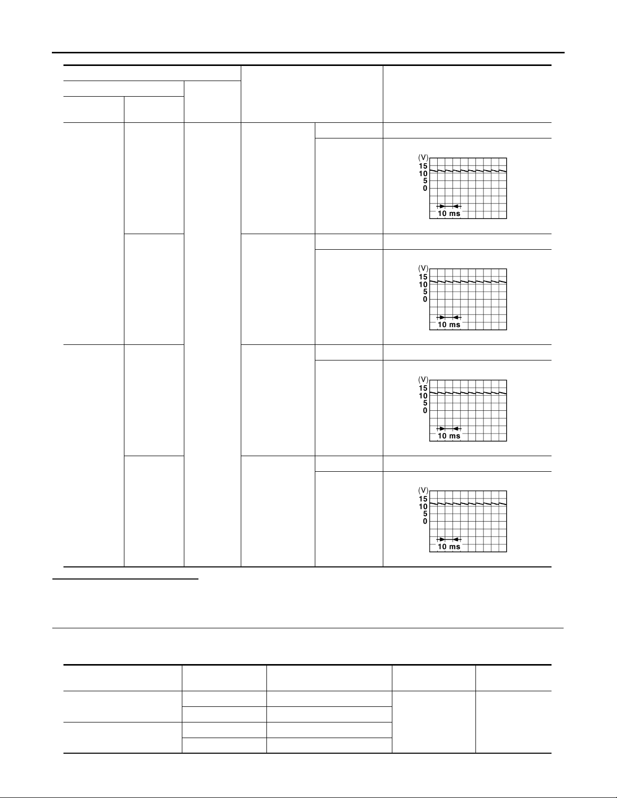
< COMPONENT DIAGNOSIS >
Revision: October 2006
2007 G35 Sedan
Terminals
(+)
BCM
connector
Terminal
(–)
DOOR SWITCH
Door condition
OPEN 0
[INTELLIGENT KEY SYSTEM]
Voltage (V)
(Approx.)
M123
M121
150
124 Passenger side
Ground
68 Rear RH
Driver side
CLOSE
JPMIA0011GB
OPEN 0
CLOSE
JPMIA0011GB
OPEN 0
CLOSE
JPMIA0011GB
OPEN 0
Is the inspection result normal?
YES >> GO TO 4.
NO >> GO TO 2.
2.CHECK DOOR SWITCH CIRCUIT
1. Disconnect BCM connector.
2. Check continuity between BCM connector and door switch connector.
BCM connector Terminal
3. Check continuity between BCM connector and ground.
M123
M121
69 Rear LH
150 B16 (Driver side)
124 B216 (Passenger side)
68 B223 (Rear RH)
69 B23 (Rear LH)
DLK-66
CLOSE
Door switch
connector
JPMIA0011GB
Terminal Continuity
2 Existed
Page 67

< COMPONENT DIAGNOSIS >
Revision: October 2006
2007 G35 Sedan
DOOR SWITCH
[INTELLIGENT KEY SYSTEM]
BCM connector Terminal
M123
M121
150
124
68
69
Ground
Continuity
Not existed
Is the inspection result normal?
YES >> GO TO 3.
NO >> Repair or replace harness between BCM and door switch.
3.CHECK DOOR SWITCH
Refer to DLK-67, "
Is the inspection result normal?
YES >> GO TO 4.
NO >> Replace malfunctioning door switch. Refer to DLK-218, "
Component Inspection".
Removal and Installation".
4.CHECK INTERMITTENT INCIDENT
Refer to GI-39, "
>> INSPECTION END
Component Inspection INFOID:0000000000961139
Intermittent Incident".
1.CHECK DOOR SWITCH
A
B
C
D
E
F
G
H
1. Turn ignition switch OFF.
2. Disconnect door switch connector.
3. Check door switch.
Terminal
Door switch
2 Ground part of door switch
Door switch condition Continuity
Is the inspection result normal?
YES >> INSPECTION END.
NO >> Replace malfunction door switch. Refer to DLK-218, "
Pressed Not existed
Released Existed
Removal and Installation".
I
J
DLK
L
M
N
O
P
DLK-67
Page 68
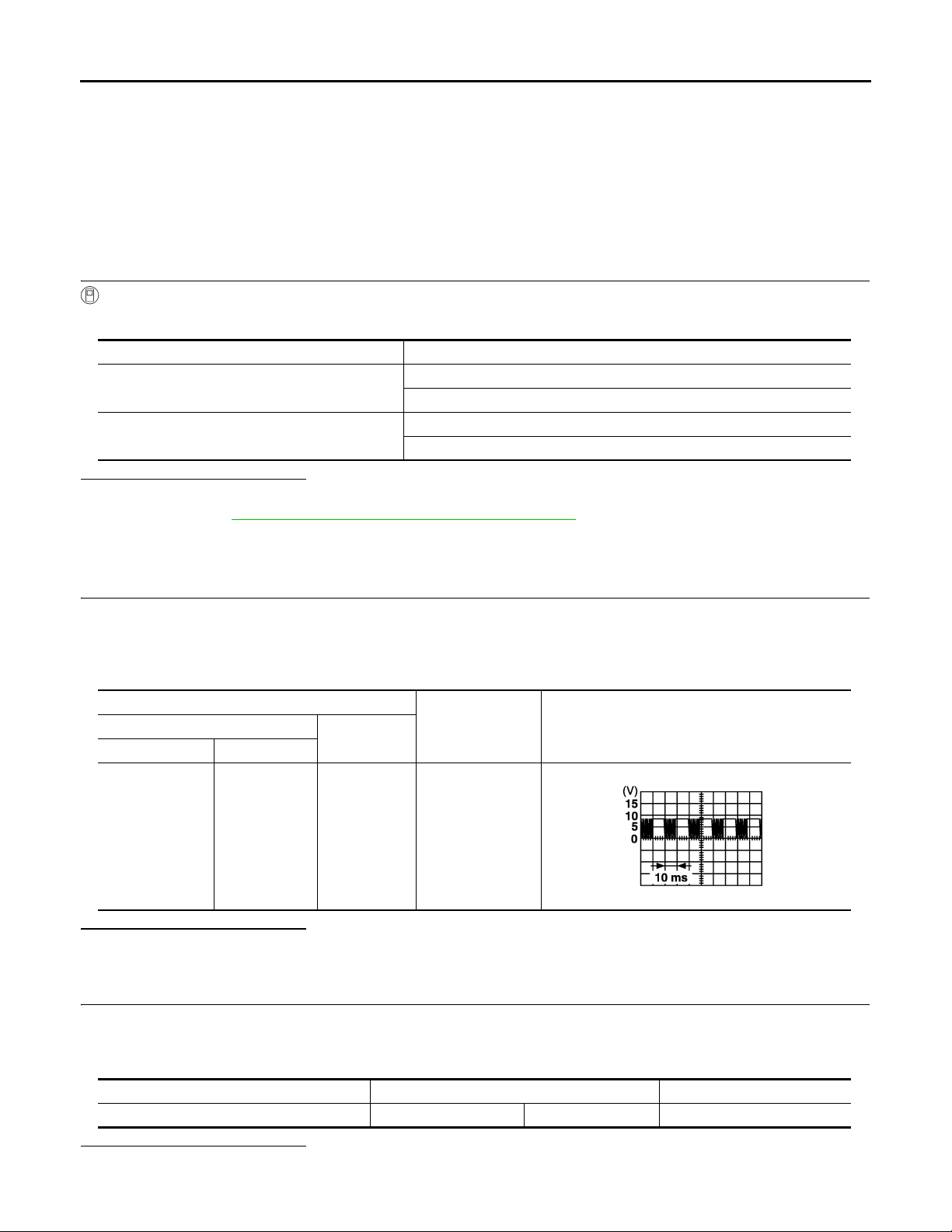
DOOR LOCK AND UNLOCK SWITCH
Revision: October 2006
2007 G35 Sedan
< COMPONENT DIAGNOSIS >
[INTELLIGENT KEY SYSTEM]
DOOR LOCK AND UNLOCK SWITCH
DRIVER SIDE
DRIVER SIDE : Description INFOID:0000000000961140
Transmits door lock/unlock operation to BCM.
DRIVER SIDE : Component Function Check INFOID:0000000000961141
1.CHECK FUNCTION
With CONSULT-III
Check (“CDL LOCK SW ”, “CDL UNLOCK SW”) in Data Monitor mode with CONSULT-III.
Monitor item Condition
CDL LOCK SW
CDL UNLOCK SW
Is the inspection result normal?
YES >> Door lock and unlock switch is OK.
NO >> Refer to DLK-68, "
DRIVER SIDE : Diagnosis Procedure".
LOCK : ON
UNLOCK : OFF
LOCK : OFF
UNLOCK : ON
DRIVER SIDE : Diagnosis Procedure INFOID:0000000000961142
1.CHECK POWER WINDOW SWITCH OUTPUT SIGNAL
1. Read voltage signal between BCM connector and ground with oscilloscope when door lock and unlock
switch (driver side) is turned “LOCK” or “UNLOCK”.
2. Check that signals which are shown in the figure below can be detected during 10 second just after door
lock and unlock switch (driver side) is turned “LOCK” or “UNLOCK”.
Terminal
(+)
BCM connector Terminal
M123 132 Ground Door is closed
Is the inspection result normal?
YES >> GO TO 4.
NO >> GO TO 2.
(–)
Condition
Signal
(Reference value)
PIIA1297E
2.CHECK POWER WINDOW SWITCH GROUND
1. Turn ignition switch OFF.
2. Disconnect power window main switch connector.
3. Check continuity between power window main switch connector and ground.
Power window main switch connector Terminal Continuity
Is the inspection result normal?
YES >> GO TO 3.
D9 17 Ground Existed
DLK-68
Page 69

DOOR LOCK AND UNLOCK SWITCH
Revision: October 2006
2007 G35 Sedan
< COMPONENT DIAGNOSIS >
NO >> Repair or replace harness.
[INTELLIGENT KEY SYSTEM]
3.CHECK POWER WINDOW SERIAL LINK CIRCUIT
1. Disconnect BCM connector.
2. Check continuity between BCM connector and power window main switch connector.
A
B
BCM connector Terminal
M123 132 D8 14 Existed
Is the inspection result normal?
YES >> GO TO 4.
NO >> Repair or replace harness.
Power window main switch
connector
Terminal Continuity
4.CHECK INTERMITTENT INCIDENT
Refer to GI-39, "
>> INSPECTION END.
DRIVER SIDE : Special Repair Requirement INFOID:0000000000961143
INITIALIZATION PROCEDURE
1. Disconnect battery minus terminal or power window main switch connector . Reconnect it after a minute or
more.
2. Turn ignition switch ON.
3. Operate power window switch to fully open the window. (This operation is unnecessary if the window is
already fully open)
4. Continue pulling the power window switch UP (AUTO-UP operation). Even after glass stop s at fully closed
position, keep pulling the switch for 3 seconds or more.
5. Inspect anti-pinch function.
Intermittent Incident".
C
D
E
F
G
H
I
CHECK ANTI-PINCH FUNCTION
1. Fully open the door window.
2. Place a piece of wood near fully closed position.
3. Close door glass completely with AUTO-UP.
• Check that glass lowers for approximately 150 mm or 2 seconds without pinching piece of wood and stops.
• Check that glass does not rise when operating the power window main switch while lowering.
CAUTION:
• Do not check with hands and other part of body because they may be pinched. Do not get pinched.
• Check that AUTO-UP operates before inspection when system initialization is performed.
• It may switch to fail-safe mode if open/close operation is performed continuously. Perform initial
setting in that situation. Refer to PWC-89, "
• Perform initial setting when auto-up operation or anti-pinch function does not operate normally.
• Finish initial setting. Otherwise, next operation cannot be done.
1. Auto-up operation
2. Anti-pinch function
3. Retained power operation when ignition switch is OFF.
Fail Safe"
PASSENGER SIDE
PASSENGER SIDE : Description INFOID:0000000000961144
Transmits door lock/unlock operation to BCM.
PASSENGER SIDE : Component Function Check INFOID:0000000000961145
1.CHECK FUNCTION
J
DLK
L
M
N
O
P
With CONSULT-III
Check (“CDL LOCK SW ”, “CDL UNLOCK SW”) in Data Monitor mode with CONSULT-III.
DLK-69
Page 70
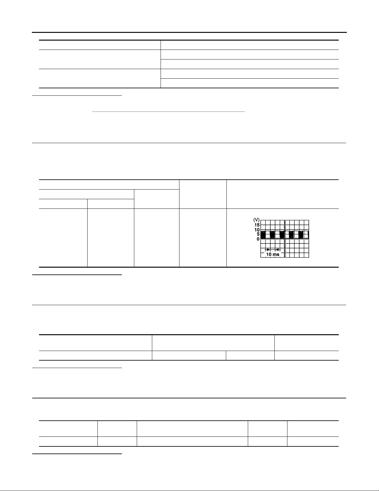
DOOR LOCK AND UNLOCK SWITCH
Revision: October 2006
2007 G35 Sedan
< COMPONENT DIAGNOSIS >
Monitor item Condition
CDL LOCK SW
CDL UNLOCK SW
Is the inspection result normal?
YES >> Door lock and unlock switch is OK.
NO >> Refer to DLK-70, "
PASSENGER SIDE : Diagnosis Procedure".
LOCK : ON
UNLOCK : OFF
LOCK : OFF
UNLOCK : ON
[INTELLIGENT KEY SYSTEM]
PASSENGER SIDE : Diagnosis Procedure INFOID:0000000000961146
1.CHECK POWER WINDOW SWITCH OUTPUT SIGNAL
1. Read voltage signal between BCM connector and ground with oscilloscope when door lock and unlock
switch (passenger side) is turned “LOCK” or “UNLOCK”.
2. Check that signals which are shown in the figure below can be detected during 10 second just after door
lock and unlock switch (passenger side) is turned “LOCK” or “UNLOCK”.
Terminal
(+)
BCM connector Terminal
(–)
Condition
Signal
(Reference value)
M123 132 Ground Door is closed
PIIA1297E
Is the inspection result normal?
YES >> GO TO 4.
NO >> GO TO 2.
2.CHECK POWER WINDOW SWITCH GROUND
1. Turn ignition switch OFF.
2. Disconnect front power window switch (passenger side) connector.
3. Check continuity between front power window switch (passenger side) connector and ground.
Front power window switch
(passenger side) connector
D38 11 Ground Existed
Terminal Continuity
Is the inspection result normal?
YES >> GO TO 3.
NO >> Repair or replace harness.
3.CHECK POWER WINDOW SERIAL LINK CIRCUIT
1. Disconnect BCM connector.
2. Check continuity between BCM connector and front power window switch (passenger side) connector.
BCM connector Terminal
Is the inspection result normal?
YES >> GO TO 4.
NO >> Repair or replace harness.
Front power window switch (passenger side)
connector
M123 132 D38 16 Existed
Terminal Continuity
DLK-70
Page 71

DOOR LOCK AND UNLOCK SWITCH
Revision: October 2006
2007 G35 Sedan
< COMPONENT DIAGNOSIS >
[INTELLIGENT KEY SYSTEM]
4.CHECK INTERMITTENT INCIDENT
Refer to GI-39, "
YES >> INSPECTION END.
PASSENGER SIDE : Special Rep air Requirement INFOID:0000000000961147
INITIALIZATION PROCEDURE
1. Disconnect battery minus terminal or power window main switch connector . Reconnect it after a minute or
more.
2. Turn ignition switch ON.
3. Operate power window switch to fully open the window. (This operation is unnecessary if the window is
already fully open)
4. Continue pulling the power window switch UP (AUTO-UP operation). Even after glass stop s at fully closed
position, keep pulling the switch for 3 seconds or more.
5. Inspect anti-pinch function.
CHECK ANTI-PINCH FUNCTION
1. Fully open the door window.
2. Place a piece of wood near fully closed position.
3. Close door glass completely with AUTO-UP.
• Check that glass lowers for approximately 150 mm or 2 seconds without pinching piece of wood and stops.
• Check that glass does not rise when operating the power window main switch while lowering.
CAUTION:
• Do not check with hands and other part of body because they may be pinched. Do not get pinched.
• Check that AUTO-UP operates before inspection when system initialization is performed.
• It may switch to fail-safe mode if open/close operation is performed continuously. Perform initial
setting in that situation. Refer to PWC-89, "
• Perform initial setting when auto-up operation or anti-pinch function does not operate normally.
• Finish initial setting. Otherwise, next operation cannot be done.
1. Auto-up operation
2. Anti-pinch function
3. Retained power operation when ignition switch is OFF.
Intermittent Incident".
Fail Safe"
A
B
C
D
E
F
G
H
I
J
DLK
L
M
N
O
P
DLK-71
Page 72
KEY SLOT
Revision: October 2006
2007 G35 Sedan
< COMPONENT DIAGNOSIS >
[INTELLIGENT KEY SYSTEM]
KEY SLOT
Description INFOID:0000000000961148
Detect whether Intelligent Key is inserted.
Immobilizer antenna amp checks Intelligent Key transponder.
Component Function Check INFOID:0000000000961149
1.CHECK FUNCTION
With CONSULT-III
Check key slot (“KEY SW -SLOT”) in Data Monitor mode with CONSULT-III.
Monitor item Condition
KEY SW-SLOT
Is the inspection result normal?
YES >> Key slot is OK.
NO >> Refer to DLK-72, "
Diagnosis Procedure".
Diagnosis Procedure INFOID:0000000000961150
Key is inserted in key slot: ON
Key is removed from key slot: OFF
1.CHECK KEY SLOT POWER SUPPLY CIRCUIT
1. Turn ignition switch OFF.
2. Disconnect key slot connector.
3. Check voltage between slot connector and ground.
Terminals
(+)
Key slot connector Terminal
M22
Is the inspection result normal?
YES >> GO TO 2.
NO >> Repair or replace key slot power supply circuit.
1
5
2.CHECK KEY SLOT GROUND CIRCUIT
Check continuity between key slot connector and ground.
Key slot connector Terminal
M22 7 Existed
Is the inspection result normal?
YES >> GO TO 3.
NO >> Repair or replace key slot ground circuit.
3.CHECK KEY SLOT CIRCUIT
Voltage (V)
(–)
Ground Battery voltage
Ground
(Approx.)
Continuity
1. Disconnect BCM connector.
2. Check continuity between BCM connector and key slot connector.
BCM connector Terminal Key slot connector Terminal Continuity
3. Check continuity between BCM connector and ground.
M123 121 M22 1 1 Existed
DLK-72
Page 73
< COMPONENT DIAGNOSIS >
Revision: October 2006
2007 G35 Sedan
KEY SLOT
[INTELLIGENT KEY SYSTEM]
BCM connector Terminal
M123 121 Not existed
Is the inspection result normal?
YES >> GO TO 4.
NO >> Repair or replace harness between BCM and key slot.
Ground
Continuity
4.CHECK KEY SLOT
Refer to DLK-73, "
Is the inspection result normal?
YES >> GO TO 5.
NO >> Replace key slot. Refer to DLK-223, "
Component Inspection".
Removal and Installation".
5.CHECK INTERMITTENT INCIDENT
Refer to GI-39, "
>> INSPECTION END
Component Inspection INFOID:0000000000961151
Intermittent Incident".
1.CHECK KEY SLOT
Check key slot.
Terminal
Key slot
111
Is the inspection result normal?
YES >> INSPECTION END.
NO >> Replace key slot. Refer to DLK-223, "
Condition Continuity
Intelligent Key inserted Existed
Intelligent Key removed Not existed
Removal and Installation".
A
B
C
D
E
F
G
H
I
J
DLK
L
M
N
O
P
DLK-73
Page 74

KEY CYLINDER SWITCH
Revision: October 2006
2007 G35 Sedan
< COMPONENT DIAGNOSIS >
[INTELLIGENT KEY SYSTEM]
KEY CYLINDER SWITCH
Description INFOID:0000000000961152
Power window main switch detects condition of the door key cylinder switch and transmits to BCM as the
LOCK or UNLOCK signals.
Component Function Check INFOID:0000000000961153
1.CHECK DOOR KEY CYLINDER SWITCH INPUT SIGNAL
Check (“KEY CYL LK-SW”, “KEY CYL UN-SW”) in “DATA MONITOR” mode for “POWER DOOR LOCK SYSTEM” with CONSULT-III. Refer to DLK-50, "
Monitor item Condition
KEY CYL LK-SW
KEY CYL UN-SW
Is the inspection result normal?
YES >> Key cylinder switch is OK.
NO >> Refer to DLK-74, "
Diagnosis Procedure".
DOOR LOCK : CONSULT-III Function (BCM - DOOR LOCK)".
Lock : ON
Neutral / Unlock : OFF
Unlock : ON
Neutral / Lock : OFF
Diagnosis Procedure INFOID:0000000000961154
1.CHECK DOOR KEY CYLINDER SWITCH INPUT SIGNAL
1. Turn ignition switch ON.
2. Check voltage between power window main switch connector and ground.
Terminals
Voltage (V)
(Approx.)
Power window main
switch connector
D8
(+)
Terminal
4
6
(–)
Ground
Key position
Lock 0
Neutral / Unlock 5
Unlock 0
Neutral / Lock 5
Is the inspection result normal?
YES >> Replace power window main switch. Refer to PWC-126, "Removal and Installation". After that,
Refer to PWC-16, "
POWER WINDOW MAIN SWITCH : Special Repair Requirement".
NO >> GO TO 2.
2.CHECK DOOR KEY CYLINDER SIGNAL CIRCUIT
1. Turn ignition switch OFF.
2. Disconnect power window main switch connector and front door key lock assembly (driver side) (key cylinder switch) connector.
3. Check continuity between power window main switch connector and front door lock assembly (driver side)
(key cylinder switch) connector.
Power window main switch connec-
4. Check continuity between power window main switch connector and ground.
tor
D8
Terminal
Front door lock assembly (driver side) (key cylin-
der switch) connector
4
65
D15
Terminal Continuity
6
Existed
DLK-74
Page 75
< COMPONENT DIAGNOSIS >
Revision: October 2006
2007 G35 Sedan
KEY CYLINDER SWITCH
[INTELLIGENT KEY SYSTEM]
Power window main switch connec-
tor
D8
Terminal
4
6
Continuity
Ground
Not existed
Is the inspection result normal?
YES >> GO TO 3.
NO >> Repair or replace harness.
3.CHECK DOOR KEY CYLINDER SWITCH GROUND CIRCUIT
Check continuity between front door lock assembly (driver side) connector and ground.
Front door lock assembly (driver side) co nnector Terminal
D15 4 Existed
Ground
Continuity
Is the inspection result normal?
YES >> GO TO 4.
NO >> Repair or replace harness.
4.CHECK DOOR KEY CYLINDER SWITCH
Check door key cylinder switch.
Refer to DLK-75, "
Is the inspection result normal?
YES >> Check intermittent incident. Refer to GI-39, "Intermittent Incident".
NO >> Replace front door lock assembly (driver side) (key cylinder switch). Refer to DLK-207, "
Component Inspection INFOID:0000000000961155
Component Inspection".
FRONT
DOOR LOCK : Removal and Installation". After that, Refer to DLK-75, "Special Repair Requirement".
A
B
C
D
E
F
G
H
I
COMPONENT INSPECTION
1.CHECK DOOR KEY CYLINDER SWITCH
Check front door lock assembly (driver side) (key cylinder switch).
Terminal
Front door lock assembly (driver side) (key cylinder
switch) connector
5
4
6
Key position Continuity
Unlock Existed
Neutral / Lock Not existed
Lock Existed
Neutral / Unlock Not existed
Is the inspection result normal?
YES >> Key cylinder switch is OK.
NO >> Replace front door lock assembly (driver side) (key cylinder switch). Refer to DLK-207, "
FRONT
DOOR LOCK : Removal and Installation". After that, Refer to DLK-75, "Special Repair Requirement".
Special Repair Requirement INFOID:0000000000961156
1.PERFORM INITIALIZATION PROCEDURE
Perform initialization procedure.
Refer to PWC-7, "
Repair Requirement".
Is the inspection result normal?
ADDITIONAL SERVICE WHEN REMOVING BATTERY NEGATIVE TERMINAL : Special
J
DLK
L
M
N
O
P
DLK-75
Page 76

KEY CYLINDER SWITCH
Revision: October 2006
2007 G35 Sedan
< COMPONENT DIAGNOSIS >
YES >> Inspection end.
NO >> Check intermittent incident. Refer to GI-39, "
[INTELLIGENT KEY SYSTEM]
Intermittent Incident".
DLK-76
Page 77
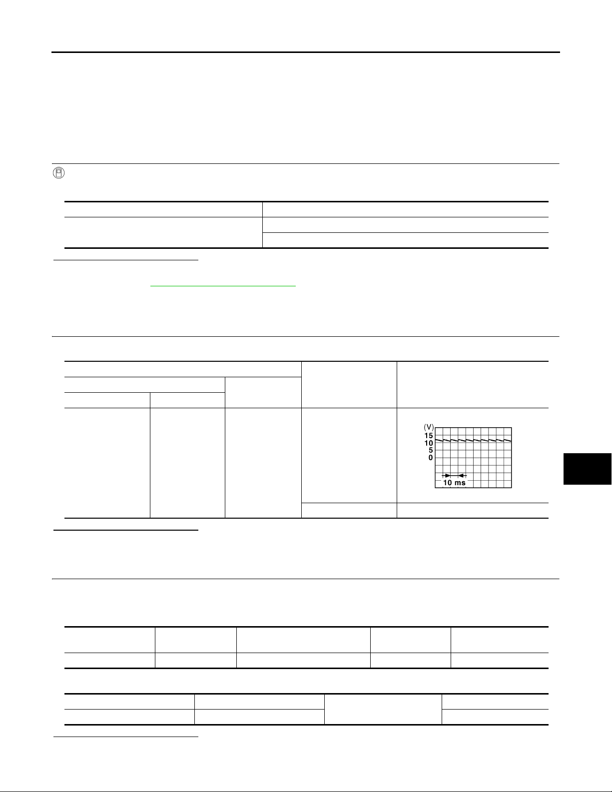
< COMPONENT DIAGNOSIS >
Revision: October 2006
2007 G35 Sedan
UNLOCK SENSOR
[INTELLIGENT KEY SYSTEM]
UNLOCK SENSOR
Description INFOID:0000000000961157
Detects door lock condition of driver door.
Component Function Check INFOID:0000000000961158
1.CHECK FUNCTION
With CONSULT-III
Check unlock sensor (“DOOR STAT SW”) in “Data Monitor” mode.
Monitor item Condition
DOOR STAT SW
Front door lock (driver side) LOCK: OFF
Front door lock (driver side) UNLOCK: ON
Is the inspection result normal?
YES >> Unlock sensor is OK.
NO >> Refer to DLK-77, "
Diagnosis Procedure".
Diagnosis Procedure INFOID:0000000000961159
1.CHECK UNLOCK SENSOR POWER SUPPLY
Check signal between BCM connector and ground with oscilloscope.
A
B
C
D
E
F
G
H
Terminals
(+)
BCM connector Terminal
M123 119 Ground
(–)
Front door lock
(driver side)
condition
Locked
Unlocked 0
Voltage (V)
(Approx.)
JPMIA0011GB
Is the inspection result normal?
YES >> GO TO 6.
NO >> GO TO 2.
2.CHECK UNLOCK SENSOR CIRCUIT
1. Turn ignition switch OFF.
2. Disconnect BCM and front door lock assembly (driver side) connector.
3. Check continuity between BCM connector and front door lock assembly (driver side) connector.
BCM connector Terminal
M123 119 D15 3 Existed
4. Check continuity between BCM connector and ground.
Front door lock assembly (dri ver
side) connector
Terminal Continuity
I
J
DLK
L
M
N
O
P
Is the inspection result normal?
YES >> GO TO 3.
BCM connector Terminal
M123 119 Not existed
Ground
DLK-77
Continuity
Page 78
UNLOCK SENSOR
Revision: October 2006
2007 G35 Sedan
< COMPONENT DIAGNOSIS >
NO >> Repair or replace harness between BCM and front door lock assembly (driver side).
[INTELLIGENT KEY SYSTEM]
3.CHECK UNLOCK SENSOR GROUND CIRCUIT
Check continuity between front door lock assembly (driver side) connector and ground.
Front door lock
assembly (driver side) connector
D15 4 Existed
Is the inspection result normal?
YES >> GO TO 4.
NO >> Repair or replace harness.
Terminal
Ground
4.CHECK BCM OUTPUT SIGNAL
1. Connect BCM harness connector.
2. Check signal between BCM connector and ground with oscilloscope.
Terminals
(+)
BCM connector Terminal
M123 119 Ground
Is the inspection result normal?
YES >> GO TO 5.
NO >> Replace BCM. BCS-79, "
Removal and Installation"
(–)
5.CHECK UNLOCK SENSOR
Continuity
Voltage (V)
(Approx.)
JPMIA0011GB
Refer to DLK-78, "
Is the inspection result normal?
YES >> GO TO 6.
NO >> Replace front door lock assembly (driver side). Refer to DLK-207, "
Component Inspection".
FRONT DOOR LOCK :
Removal and Installation".
6.CHECK INTERMITTENT INCIDENT
Refer to GI-39, "
>> INSPECTION END.
Component Inspection INFOID:0000000000961160
Intermittent Incident".
1.CHECK UNLOCK SENSOR
Check unlock sensor.
Terminal
Front door lock assembly (driver side )
34
Is the inspection result normal?
YES >> INSPECTION END.
Front door lock assembly (driver side) condition Continuity
Unlock Existed
Lock Not existed
DLK-78
Page 79

UNLOCK SENSOR
Revision: October 2006
2007 G35 Sedan
< COMPONENT DIAGNOSIS >
NO >> Replace front lock assembly (driver side). Refer to DLK-207, "FRONT DOOR LOCK : Removal
and Installation".
[INTELLIGENT KEY SYSTEM]
A
B
C
D
E
F
G
H
I
J
DLK
L
M
N
O
P
DLK-79
Page 80
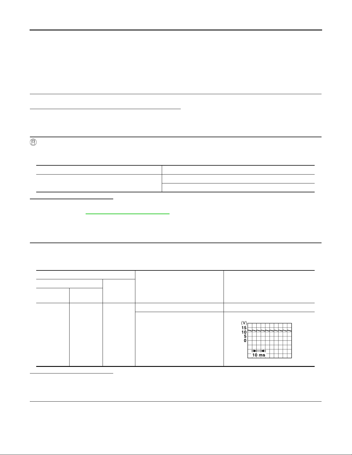
TRUNK LID OPENER SWITCH
Revision: October 2006
2007 G35 Sedan
< COMPONENT DIAGNOSIS >
[INTELLIGENT KEY SYSTEM]
TRUNK LID OPENER SWITCH
Description INFOID:0000000000961161
Transmits trunk lid open signal to BCM.
Component Function Check INFOID:0000000000961162
1.CHECK TRUNK LID OPENER CANCEL SWITCH
Check trunk lid opener cancel switch position.
Does trunk lid opener cancel switch turn ON (CANCEL)?
Yes >> Turn off trunk lid opener cancel switch.
No >> GO TO 2.
2.CHECK FUNCTION
With CONSULT-III
Check trunk lid opener switch (“TR/BD OPEN SW”) in “Data Monitor mode with CONSUL T-III.
• When trunk lid opener switch is turned to “ON”.
Monitor item Condition
TR/BD OPEN SW
Is the inspection result normal?
YES >> Trunk lid opener switch is OK.
NO >> Refer to DLK-80, "
Diagnosis Procedure".
Trunk lid opener switch is pressed: ON
Trunk lid opener switch is released: OFF
Diagnosis Procedure INFOID:0000000000961163
1.CHECK TRUNK LID OPEN INPUT SIGNAL
1. Remove Intelligent Key from key slot.
2. Turn on trunk lid opener cancel switch.
3. Check voltage between BCM connector and ground.
Terminals
(+)
BCM
connector
M121 67 Ground
Is the inspection result normal?
YES >> GO TO 2.
NO >> GO TO 5.
Terminal
(–)
Condition of trunk lid opener switch
ON (press and hold) 0
OFF (release)
Voltage (V)
(Approx.)
JPMIA0011GB
2.CHECK TRUNK LID OPENER SWITCH CIRCUIT
1. Disconnect BCM connector.
2. Check continuity between BCM connector and trunk lid opener switch connector.
DLK-80
Page 81

< COMPONENT DIAGNOSIS >
Revision: October 2006
2007 G35 Sedan
TRUNK LID OPENER SWITCH
[INTELLIGENT KEY SYSTEM]
BCM connector Terminal Trunk lid opener switch connector Terminal Continuity
M121 67 M20 1 Existed
3. Check continuity between BCM connector and ground.
BCM connector Terminal
M121 67 Not existed
Is the inspection result normal?
YES >> GO TO 3.
NO >> Repair harness or connector.
Ground
3.CHECK TRUNK LID OPENER SWITCH GROUND CIRCUIT
Check continuity between trunk lid opener switch connector and ground.
Trunk lid opener switch Terminal
M20 2 Existed
Is the inspection result normal?
YES >> GO TO 4.
NO >> Repair or replace harness.
Ground
4.CHECK TRUNK LID OPENER SWITCH
Refer to DLK-81, "
Is the inspection result normal?
YES >> GO TO 5.
NO >> Replace trunk lid opener switch. Refer to DLK-225, "
Component Inspection".
Removal and Installation".
5.CHECK INTERMITTENT INCIDENT
A
B
Continuity
C
D
E
Continuity
F
G
H
I
Refer to GI-39, "
>> INSPECTION END.
Intermittent Incident".
Component Inspection INFOID:0000000000961164
1.CHECK TRUNK LID OPENER SWITCH
1. Turn ignition switch OFF.
2. Disconnect trunk lid opener switch connector.
3. Check continuity between trunk lid opener switch connector.
Terminal
Trunk lid opener switch
12
Is the inspection result normal?
YES >> INSPECTION END.
NO >> Replace trunk lid opener switch. Refer to DLK-225, "
Condition Continuity
ON (press and hold) Existed
OFF (release) Not existed
Removal and Installation".
J
DLK
L
M
N
O
P
DLK-81
Page 82

TRUNK LID OPENER CANCEL SWITCH
B
Revision: October 2006
2007 G35 Sedan
< COMPONENT DIAGNOSIS >
[INTELLIGENT KEY SYSTEM]
TRUNK LID OPENER CANCEL SWITCH
Description INFOID:0000000000961165
Cancels trunk lid open operation.
Component Function Check INFOID:0000000000961166
1.CHECK FUNCTION
With CONSULT-III
Check trunk lid opener cancel switch (“TR CANCEL SW”) in Data Monitor mode with CONSULT-III.
Monitor item Condition
TR CANCEL SW
Is the inspection result normal?
YES >> Trunk lid opener cancel switch is OK.
NO >> Refer to DLK-82, "
Diagnosis Procedure".
Diagnosis Procedure INFOID:0000000000961167
Trunk lid opener cancel switch is turned to “ON”: ON
Trunk lid opener cancel switch is turned to “OFF”: OFF
1.CHECK TRUNK LID OPENER CANCEL SIGNAL
1. Check voltage between BCM connector and ground.
Terminals
(+)
BCM
connector
M123 129 Ground
Terminal
(–)
Condition of trunk lid opener
cancel switch
ON (press and hold) 0
OFF (cancel)
Voltage (V)
(Approx.)
Is the inspection result normal?
YES >> GO TO 2.
NO >> GO TO 5.
2.CHECK TRUNK LID OPENER CANCEL SWITCH CIRCUIT
1. Disconnect BCM connector.
2. Check continuity between BCM connector and trunk lid opener cancel switch connector.
JPMIA0012G
BCM connector T erminal Trunk lid opener cancel switch connector Terminal Continuity
M123 129 M105 1 Existed
3. Check continuity between BCM connector and ground.
Is the inspection result normal?
YES >> GO TO 3.
NO >> Repair harness or connector.
BCM connector Terminal
M123 129 Not existed
Ground
DLK-82
Continuity
Page 83

TRUNK LID OPENER CANCEL SWITCH
Revision: October 2006
2007 G35 Sedan
< COMPONENT DIAGNOSIS >
[INTELLIGENT KEY SYSTEM]
3.CHECK TRUNK LID OPENER CANCEL SWITCH GROUND CIRCUIT
Check continuity between trunk lid opener switch connector and ground.
Trunk lid opener cancel switch Terminal
M105 2 Existed
Is the inspection result normal?
YES >> GO TO 4.
NO >> Repair or replace harness.
Ground
Continuity
4.CHECK TRUNK LID OPENER CANCEL SWITCH
Refer to DLK-83, "
Is the inspection result normal?
YES >> GO TO 5.
NO >> Replace trunk lid opener cancel switch. Refer to DLK-226, "
Component Inspection".
Removal and Installation".
5.CHECK INTERMITTENT INCIDENT
Refer to GI-39, "
>> INSPECTION END.
Component Inspection INFOID:0000000000961168
Intermittent Incident".
1.CHECK TRUNK LID OPENER CANCEL SWITCH
1. Disconnect trunk lid opener cancel switch connector.
2. Check continuity between trunk lid opener cancel switch connector.
Terminal
Trunk lid opener switch
12
Is the inspection result normal?
YES >> INSPECTION END.
NO >> Replace trunk lid opener cancel switch. Refer to DLK-226, "
Condition Continuity
ON Existed
OFF (cancel) Not existed
Removal and Installation".
A
B
C
D
E
F
G
H
I
J
DLK
L
M
N
O
P
DLK-83
Page 84
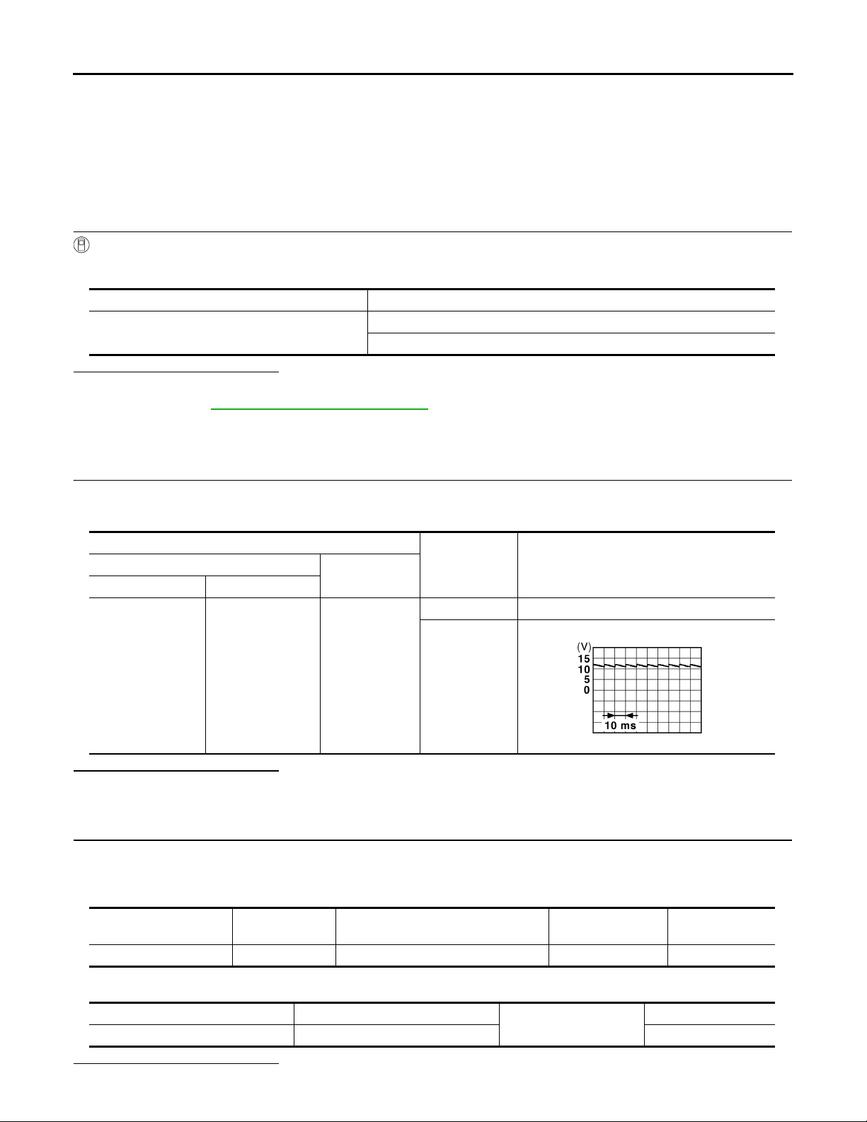
TRUNK ROOM LAMP SWITCH
Revision: October 2006
2007 G35 Sedan
< COMPONENT DIAGNOSIS >
[INTELLIGENT KEY SYSTEM]
TRUNK ROOM LAMP SWITCH
Description INFOID:0000000000961169
Detects trunk open/close condition.
Component Function Check INFOID:0000000000961170
1.CHECK FUNCTION
With CONSULT-III
Check (“TR/HAT MNTR”) in Data Monitor mode with CONSULT-III.
Monitor item Condition
TRNK/HAT MNTR
Is the inspection result normal?
YES >> Trunk room lamp switch is OK.
NO >> Refer to DLK-85, "
Component Inspection".
Diagnosis Procedure INFOID:0000000000961171
OPEN : ON
CLOSE : OFF
1.CHECK TRUNK ROOM LAMP SWITCH INPUT SIGNAL
1. Turn ignition switch OFF.
2. Check voltage between BCM connector and ground.
Terminals
(+)
BCM connector Terminal
M121 50 Ground
(–)
Trunk
condition
OPEN 0
CLOSE
Voltage (V)
(Approx.)
JPMIA0011GB
Is the inspection result normal?
YES >> GO TO 4.
NO >> GO TO 2.
2.CHECK TRUNK ROOM LAMP SWITCH CIRCUIT
1. Disconnect BCM connector.
2. Check continuity between BCM connector and trunk lid lock assembly (trunk room lamp switch) connector.
BCM connector Terminal
3. Check continuity between BCM connector and ground.
Is the inspection result normal?
Trunk lid lock assembly (trunk room
lamp switch) connector
M121 50 B303 1 Existed
BCM connector Termi na l
M121 50 Not existed
Terminal Continuity
Ground
Continuity
DLK-84
Page 85
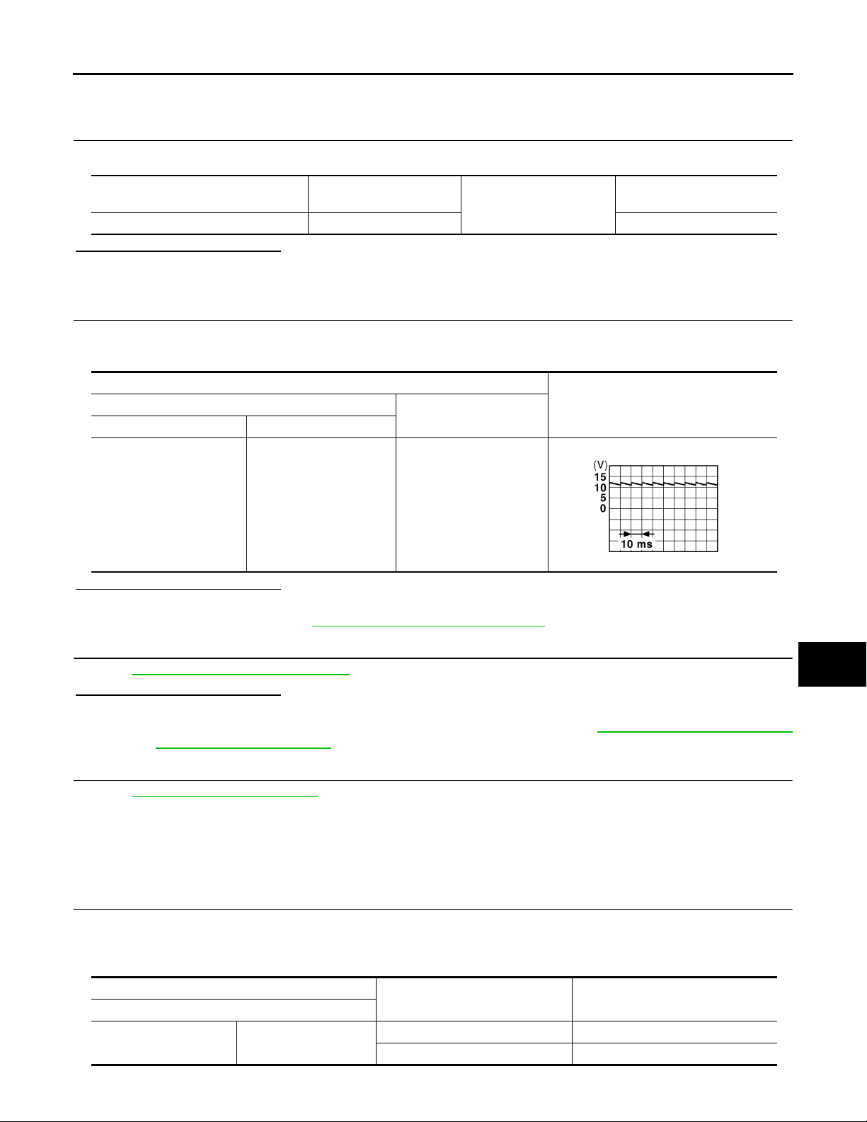
TRUNK ROOM LAMP SWITCH
Revision: October 2006
2007 G35 Sedan
< COMPONENT DIAGNOSIS >
YES >> GO TO 3.
NO >> Repair or replace harness between BCM and trunk room lamp switch.
[INTELLIGENT KEY SYSTEM]
3.CHECK TRUNK ROOM LAMP SWITCH GROUND CIRCUIT
A
Check continuity between trunk lid lock assembly connector and ground.
Trunk lid lock assembly (trunk room
lamp switch) connector
B303 2 Existed
Terminal
Ground
Is the inspection result normal?
YES >> GO TO 4.
NO >> Repair or replace trunk room lamp switch ground circuit.
4.CHECK BCM OUTPUT SIGNAL
1. Connect BCM connector.
2. Check voltage between BCM connector and ground.
Terminals
(+)
BCM connector Terminal
M121 50 Ground
(–)
Voltage (V)
Is the inspection result normal?
YES >> GO TO 5.
NO >> Replace BCM. Refer to BCS-79, "
Removal and Installation".
5.CHECK TRUNK ROOM LAMP SWITCH
Refer to DLK-85, "
Is the inspection result normal?
YES >> GO TO 6.
NO >> Replace trunk lid lock assembly (trunk room lamp switch). Refer to DLK-216, "
Component Inspection".
: Removal and Installation".
6.CHECK INTERMITTENT INCIDENT
Refer to GI-39, "
Intermittent Incident".
Continuity
(Approx.)
JPMIA0011GB
TRUNK LID LOCK
B
C
D
E
F
G
H
I
J
DLK
L
M
>> INSPECTION END.
Component Inspection INFOID:0000000000961172
1.CHECK TRUNK ROOM LAMP SWITCH
1. Turn ignition switch OFF.
2. Disconnect trunk lid lock assembly (trunk room lamp switch) connector.
3. Check trunk room lamp switch.
Terminal
Trunk room lamp switch
12
Trunk condition Continuity
DLK-85
N
O
P
OPEN Existed
CLOSE Not existed
Page 86

TRUNK ROOM LAMP SWITCH
Revision: October 2006
2007 G35 Sedan
< COMPONENT DIAGNOSIS >
Is the inspection result normal?
YES >> INSPECTION END.
NO >> Replace trunk lid lock assembly (trunk room lamp switch). Refer to DLK-216, "
: Removal and Installation".
[INTELLIGENT KEY SYSTEM]
TRUNK LID LOCK
DLK-86
Page 87
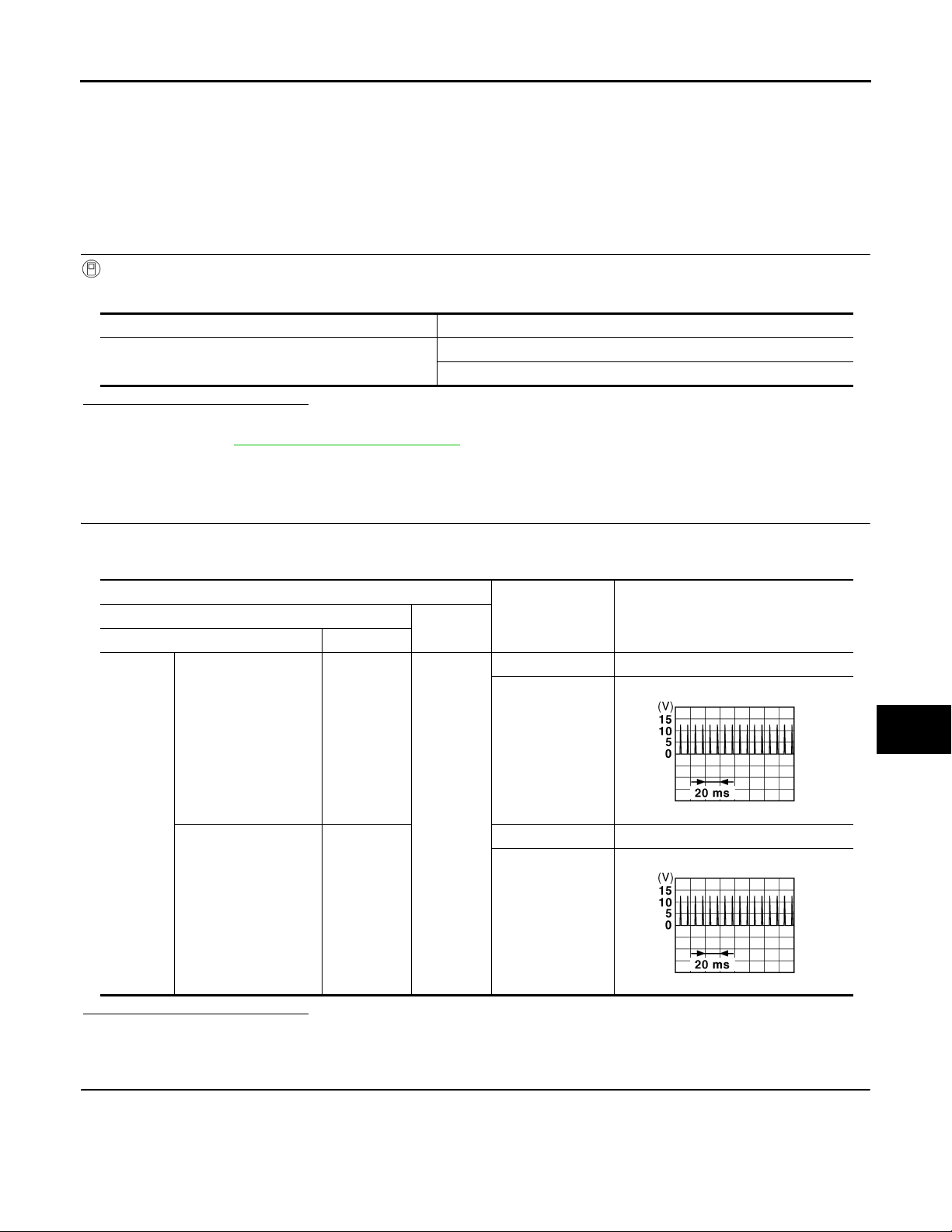
< COMPONENT DIAGNOSIS >
B
B
Revision: October 2006
2007 G35 Sedan
DOOR REQUEST SWITCH
[INTELLIGENT KEY SYSTEM]
DOOR REQUEST SWITCH
Description INFOID:0000000000961173
Transmits lock/unlock operation to BCM.
Component Function Check INFOID:0000000000961174
1.CHECK FUNCTION
With CONSULT-III
Check door request switch (“DR REQ SW” or “AS REQ SW”) in Data Monitor mode.
Monitor item Condition
DR REQ SW
AS REQ SW
Door request switch is pressed: ON
Door request switch is released : OFF
Is the inspection result normal?
YES >> Door request switch is OK.
NO >> Refer to DLK-87, "
Diagnosis Procedure".
Diagnosis Procedure INFOID:0000000000961175
1.CHECK DOOR REQUEST SWITCH OUTPUT SIGNAL
1. Turn ignition switch OFF.
2. Check voltage between BCM harness connector and ground.
A
B
C
D
E
F
G
H
Terminals
(+)
BCM connector Terminal
Door request switch
(driver side)
M122
Door request switch
(passenger side)
101
100
Is the inspection result normal?
YES >> GO TO 6.
NO >> GO TO 2.
2.CHECK DOOR REQUEST SWITCH CIRCUIT
(–)
Ground
Door request
switch Condition
Pressed 0
Released
Pressed 0
Released
Voltage (V)
(Approx.)
JMKIA0059G
JMKIA0059G
I
J
DLK
L
M
N
O
P
1. Disconnect BCM and front outside handle connector.
2. Check continuity between BCM connector and front outside handle connector.
DLK-87
Page 88
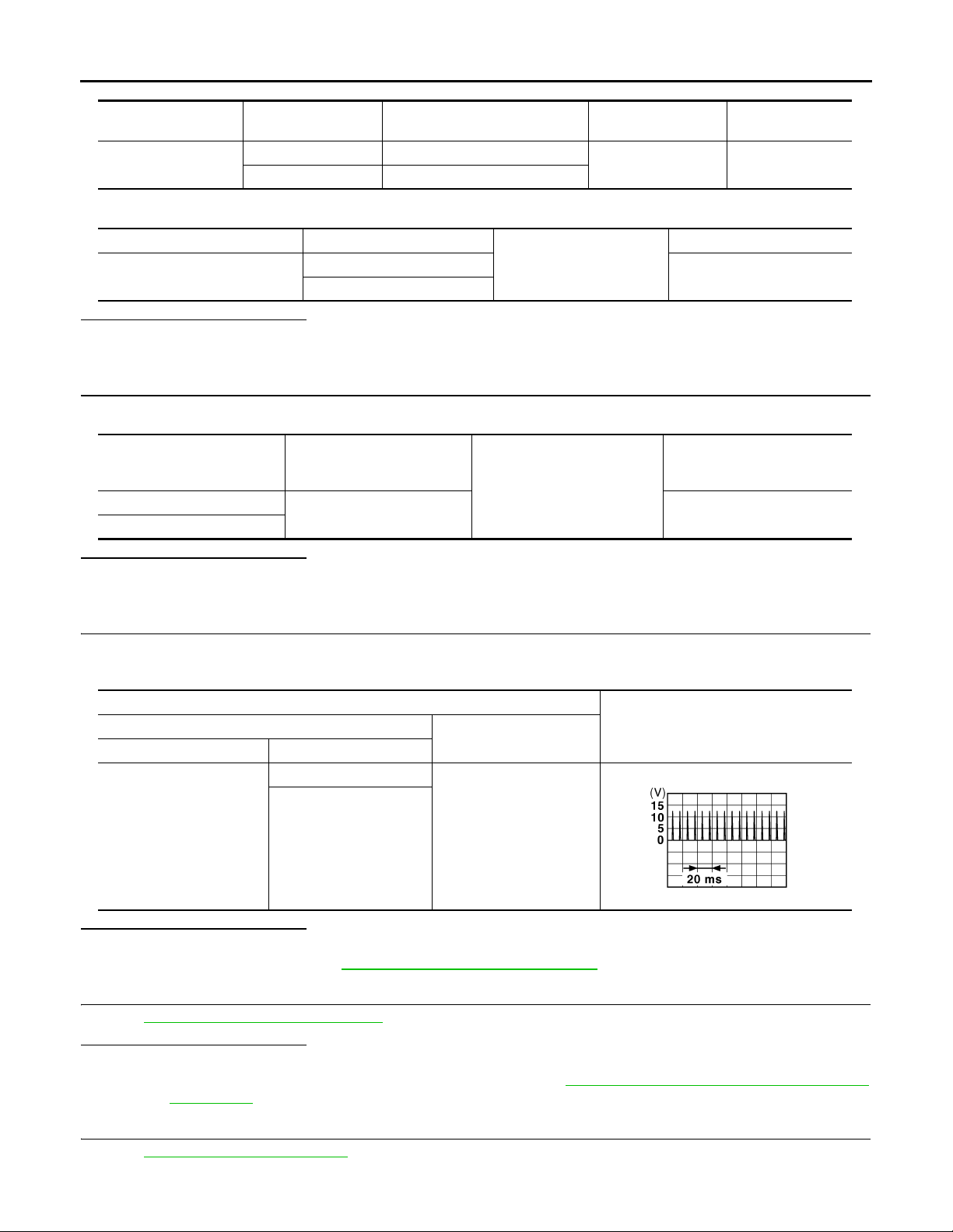
< COMPONENT DIAGNOSIS >
B
Revision: October 2006
2007 G35 Sedan
DOOR REQUEST SWITCH
[INTELLIGENT KEY SYSTEM]
BCM connector Terminal
M122
101 D13 (driver side)
100 D43 (passenger side)
Front outside
handle connector
3. Check continuity between BCM connector and ground.
BCM connector Terminal
M122
101
100
Ground
Is the inspection result normal?
YES >> GO TO 3.
NO >> Repair or replace harness between BCM and front outside handle.
3.CHECK DOOR REQUEST SWITCH GROUND CIRCUIT
Check continuity between front outside handle connector and ground.
Front outside
handle
connector
D13 (driver side)
D43 (passenger side)
Terminal
Ground
2 Existed
Is the inspection result normal?
YES >> GO TO 4.
NO >> Repair or replace front outside handle ground circuit.
4.CHECK BCM OUTPUT SIGNAL
Terminal Continuity
1 Existed
Continuity
Not existed
Continuity
1. Connect BCM connector.
2. Check voltage between BCM connector and ground.
Terminals
(+)
BCM connector Terminal
101
M122
100
(–)
Ground
Is the inspection result normal?
YES >> GO TO 5.
NO >> Replace BCM. Refer to BCS-79, "
Removal and Installation".
5.CHECK DOOR REQUEST SWITCH
Refer to DLK-89, "
Is the inspection result normal?
YES >> GO TO 6.
NO >> Replace malfunctioning front outside handle. Refer to DLK-201, "
Component Inspection".
Installation".
6.CHECK INTERMITTENT INCIDENT
Voltage (V)
(Approx.)
JMKIA0059G
FRONT DOOR : Removal and
Refer to GI-39, "
Intermittent Incident".
DLK-88
Page 89

DOOR REQUEST SWITCH
Revision: October 2006
2007 G35 Sedan
< COMPONENT DIAGNOSIS >
>> INSPECTION END
[INTELLIGENT KEY SYSTEM]
Component Inspection INFOID:0000000000961176
A
1.CHECK DOOR REQUEST SWITCH
Check front outside handle (request switch).
Terminal
Front outside handle (request switch)
12
Is the inspection result normal?
YES >> INSPECTION END.
NO >> Replace malfunction front outside handle. Refer to DLK-201, "
Installation".
Door request switch condition Continuity
Pressed Existed
Released Not existed
FRONT DOOR : Removal and
B
C
D
E
F
G
H
I
J
DLK
L
M
N
O
P
DLK-89
Page 90
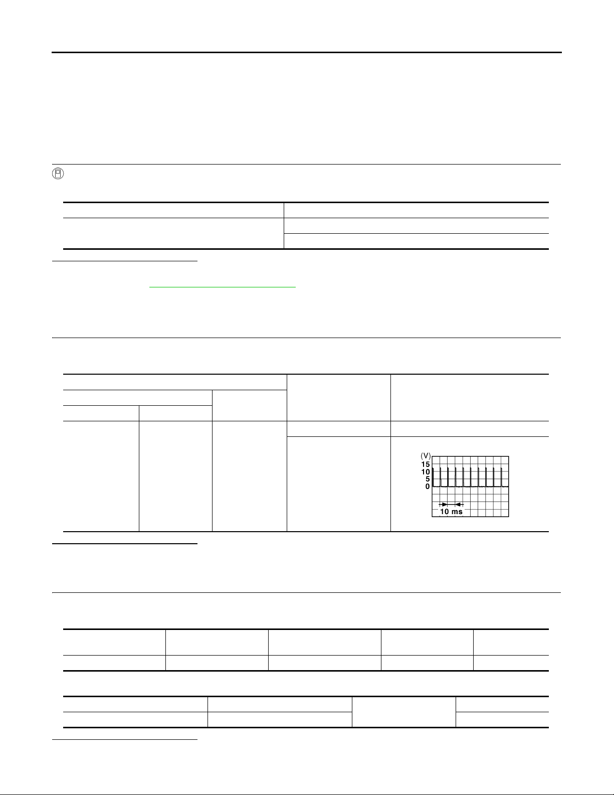
TRUNK OPENER REQUEST SWITCH
B
Revision: October 2006
2007 G35 Sedan
< COMPONENT DIAGNOSIS >
[INTELLIGENT KEY SYSTEM]
TRUNK OPENER REQUEST SWITCH
Description INFOID:0000000000961177
Performs trunk lid open request when it is pressed.
Component Function Check INFOID:0000000000961178
1.CHECK FUNCTION
With CONSULT-III
Check trunk opener request switch (“REQ SW -BD/TR ”) in Data Monitor mode.
Monitor item Condition
REQ SW -BD/TR
Is the inspection result normal?
YES >> Trunk opener request switch is OK.
NO >> Refer to DLK-90, "
Diagnosis Procedure".
Diagnosis Procedure INFOID:0000000000961179
Trunk opener request switch is pressed: ON
Trunk opener request switch is released: OFF
1.CHECK TRUNK OPENER REQUEST SWITCH OUTPUT SIGNAL
1. Turn ignition switch OFF.
2. Check voltage between BCM connector and ground.
Terminals
(+)
BCM connector Terminal
M121 61 Ground
(–)
Trunk lid opener reque st
switch condition
Pressed 0
Released
Voltage (V)
(Approx.)
Is the inspection result normal?
YES >> GO TO 6.
NO >> GO TO 2.
2.CHECK TRUNK OPENER REQUEST SWITCH CIRCUIT
1. Disconnect BCM and trunk opener request switch connector.
2. Check continuity between BCM connector and trunk opener request switch connector.
JPMIA0016G
BCM connector Terminal
3. Check continuity between BCM connector and ground.
Is the inspection result normal?
YES >> GO TO 3.
Trunk request switch con-
nector
M121 61 B304 1 Existed
BCM connector Terminal
M121 61 Not existed
Terminal Continuity
Ground
Continuity
DLK-90
Page 91
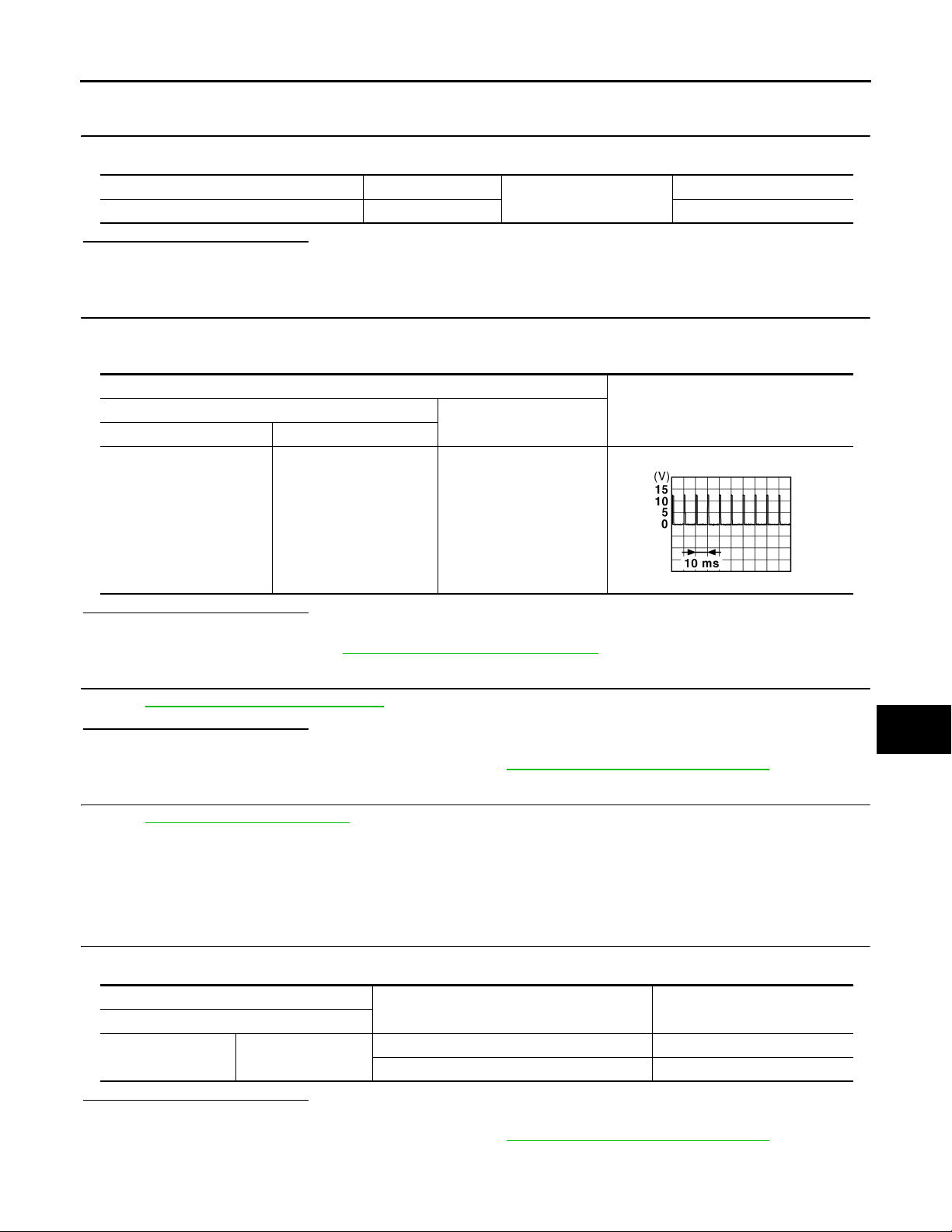
TRUNK OPENER REQUEST SWITCH
B
Revision: October 2006
2007 G35 Sedan
< COMPONENT DIAGNOSIS >
NO >> Repair or replace harness between BCM and trunk opener request switch.
[INTELLIGENT KEY SYSTEM]
3.CHECK TRUNK OPENER REQUEST SWITCH GROUND CIRCUIT
Check continuity between trunk opener request switch connector and ground.
A
Trunk opener request switch connector Terminal
B304 2 Existed
Ground
Is the inspection result normal?
YES >> GO TO 4.
NO >> Repair or replace trunk opener request switch ground circuit.
4.CHECK BCM OUTPUT SIGNAL
1. Connect BCM connector.
2. Check voltage between BCM connector and ground.
Terminals
(+)
BCM connector Terminal
M121 61 Ground
(–)
Is the inspection result normal?
YES >> GO TO 5.
NO >> Replace BCM. Refer to BCS-79, "
Removal and Installation".
5.CHECK TRUNK OPENER REQUEST SWITCH
Continuity
Voltage (V)
(Approx.)
B
C
D
E
F
G
H
JPMIA0016G
I
J
Refer to DLK-91, "
Component Inspection".
Is the inspection result normal?
YES >> GO TO 6.
NO >> Replace trunk opener request switch. Refer to DLK-224, "
Removal and Installation".
6.CHECK INTERMITTENT INCIDENT
Refer to GI-39, "
>> INSPECTION END.
Component Inspection INFOID:0000000000961180
Intermittent Incident".
1.CHECK TRUNK OPENER REQUEST SWITCH
Check trunk opener request switch.
Terminal
Trunk opener request switch
12
Is the inspection result normal?
YES >> INSPECTION END.
NO >> Replace trunk opener request switch. Refer to DLK-224, "
Trunk opener request switch condition Continuity
Pressed Existed
Released Not existed
Removal and Installation".
DLK
L
M
N
O
P
DLK-91
Page 92

DOOR LOCK ACTUATOR
Revision: October 2006
2007 G35 Sedan
< COMPONENT DIAGNOSIS >
[INTELLIGENT KEY SYSTEM]
DOOR LOCK ACTUATOR
DRIVER SIDE
DRIVER SIDE : Description INFOID:0000000000961181
Locks/unlocks the door with the signal from BCM.
DRIVER SIDE : Component Function Check INFOID:0000000000961182
1.CHECK FUNCTION
1. Use CONSULT-III to perform Active Test (“DOOR LOCK”).
2. Touch “ALL LOCK” or “ALL UNLOCK” to check that it works normally.
Is the inspection result normal?
YES >> Door lock actuator is OK.
NO >> Refer to DLK-92, "
DRIVER SIDE : Diagnosis Procedure".
DRIVER SIDE : Diagnosis Procedure INFOID:0000000000961183
1.CHECK OUTPUT SIGNAL
Check voltage between BCM connector and ground.
Terminals
(+)
BCM connector Terminal
M119
Is the inspection result normal?
YES >> GO TO 2.
NO >> GO TO 3.
Condition of door lock and
(–)
8
9 Unlock 0 → Battery voltage → 0
Ground
unlock switch
Lock 0 → Battery voltage → 0
Voltage (V)
(Approx.)
2.CHECK DOOR LOCK ACTUATOR CIRCUIT
1. Turn ignition switch OFF.
2. Disconnect BCM and front door lock actuator driver side connector.
3. Check continuity between BCM connector and front door lock actuator driver side connector.
BCM connector Terminal
M119
4. Check continuity between BCM connector and ground.
BCM connector Terminal Continuity
M119
8
92
8
9
Door lock actuator con-
nector
D15
Ground Not existed
Terminal Continuity
1
Existed
Is the inspection result normal?
YES >> GO TO 3.
NO >> Repair or replace harness.
3.CHECK INTERMITTENT INCIDENT
Refer to GI-39, "
>> INSPECTION END.
PASSENGER SIDE
Intermittent Incident".
DLK-92
Page 93

DOOR LOCK ACTUATOR
Revision: October 2006
2007 G35 Sedan
< COMPONENT DIAGNOSIS >
[INTELLIGENT KEY SYSTEM]
PASSENGER SIDE : Description INFOID:0000000000961184
Locks/unlocks the door with the signal from BCM.
A
PASSENGER SIDE : Component Function Check INFOID:0000000000961185
1.CHECK FUNCTION
1. Use CONSULT-III to perform Active Test (“DOOR LOCK”).
2. Touch “ALL LOCK” or “ALL UNLOCK” to check that it works normally.
Is the inspection result normal?
YES >> Door lock actuator is OK.
NO >> Refer to DLK-93, "
PASSENGER SIDE : Diagnosis Procedure".
PASSENGER SIDE : Diagnosis Procedure INFOID:0000000000961186
1.CHECK DOOR LOCK ACTUATOR SIGNAL
Check voltage between BCM connector and ground.
Terminals
(+)
BCM connector Terminal
M119
8
5 Unlock 0 → Battery voltage → 0
(–)
Ground
Condition of door lock and
unlock switch
Lock 0 → Battery voltage → 0
Voltage (V)
(Approx.)
Is the inspection result normal?
YES >> GO TO 2.
NO >> GO TO 3.
2.CHECK DOOR LOCK ACTUATOR CIRCUIT
B
C
D
E
F
G
H
I
1. Disconnect BCM and front door lock actuator passenger side connectors.
2. Check continuity between BCM connector and front door lock actuator passenger side.
BCM connector Terminal
M119
8
51
Door lock actuator con-
nector
D45
Terminal Continuity
2
3. Check continuity between BCM connector and ground.
BCM connector Terminal Continuity
M119
8
5
Ground Not existed
Is the inspection result normal?
YES >> GO TO 3.
NO >> Repair or replace harness.
3.CHECK INTERMITTENT INCIDENT
Refer to GI-39, "
>> INSPECTION END.
REAR LH
Intermittent Incident".
J
DLK
Existed
L
M
N
O
P
REAR LH : Description INFOID:0000000000961187
Locks/unlocks the door with the signal from BCM.
DLK-93
Page 94

< COMPONENT DIAGNOSIS >
Revision: October 2006
2007 G35 Sedan
DOOR LOCK ACTUATOR
[INTELLIGENT KEY SYSTEM]
REAR LH : Component Function Check
INFOID:0000000000961188
1.CHECK FUNCTION
1. Use CONSULT-III to perform Active Test (“DOOR LOCK”).
2. Touch “ALL LOCK” or “ALL UNLOCK” to check that it works normally.
Is the inspection result normal?
YES >> Door lock actuator is OK.
NO >> Refer to DLK-94, "
REAR LH : Diagnosis Procedure".
REAR LH : Diagnosis Procedure INFOID:0000000000961189
1.CHECK DOOR LOCK ACTUATOR SIGNAL
Check voltage between BCM connector and ground.
Terminals
(+)
BCM connector Terminal
M119
8
10 Unlock 0 → Battery voltage → 0
(–)
Ground
Condition of door lock and
unlock switch
Lock 0 → Battery voltage → 0
Voltage (V)
(Approx.)
Is the inspection result normal?
YES >> GO TO 2.
NO >> GO TO 3.
2.CHECK DOOR LOCK ACTUATOR CIRCUIT
1. Disconnect BCM and rear door lock actuator LH connectors.
2. Check continuity between BCM connector and rear door lock actuator LH connectors.
BCM connector Terminal
M119
8
10 2
Door lock actuator con-
nector
D55
Terminal Continuity
1
3. Check continuity between BCM connector and ground.
BCM connector Terminal Continuity
M119
10
8
Ground Not existed
Is the inspection result normal?
YES >> GO TO 3.
NO >> Repair or replace harness.
3.CHECK INTERMITTENT INCIDENT
Refer to GI-39, "
>> INSPECTION END.
REAR RH
Intermittent Incident".
Existed
REAR RH : Description INFOID:0000000000961190
Locks/unlocks the door with the signal from BCM.
REAR RH : Component Function Check INFOID:0000000000961191
1.CHECK FUNCTION
DLK-94
Page 95

DOOR LOCK ACTUATOR
Revision: October 2006
2007 G35 Sedan
< COMPONENT DIAGNOSIS >
1. Use CONSULT-III to perform Active Test (“DOOR LOCK”).
2. Touch “ALL LOCK” or “ALL UNLOCK” to check that it works normally.
Is the inspection result normal?
YES >> Door lock actuator is OK.
NO >> Refer to DLK-95, "
REAR RH : Diagnosis Procedure".
[INTELLIGENT KEY SYSTEM]
REAR RH : Diagnosis Procedure INFOID:0000000000961192
A
B
1.CHECK DOOR LOCK ACTUATOR SIGNAL
Check voltage between BCM connector and ground.
Terminals
(+)
BCM connector Terminal
M119
8
10 Unlock 0 → Battery voltage → 0
(–)
Ground
Condition of door lock and
unlock switch
Lock 0 → Battery voltage → 0
Voltage (V)
(Approx.)
Is the inspection result normal?
YES >> GO TO 2.
NO >> GO TO 3.
2.CHECK DOOR LOCK ACTUATOR CIRCUIT
1. Disconnect BCM and rear door lock actuator RH connectors.
2. Check continuity between BCM connector and rear door lock actuator RH connectors.
BCM connector Terminal
M119
8
10 1
3. Check continuity between BCM connector and ground.
Door lock actuator con-
nector
D75
Terminal Continuity
2
C
D
E
F
G
H
I
Existed
J
BCM connector Terminal Continuity
M119
Is the inspection result normal?
YES >> GO TO 3.
NO >> Repair or replace harness.
3.CHECK INTERMITTENT INCIDENT
Refer to GI-39, "
>> INSPECTION END.
Intermittent Incident".
10
8
Ground Not Existed
DLK
L
M
N
O
P
DLK-95
Page 96

TRUNK LID OPENER ACTUATOR
Revision: October 2006
2007 G35 Sedan
< COMPONENT DIAGNOSIS >
[INTELLIGENT KEY SYSTEM]
TRUNK LID OPENER ACTUATOR
Description INFOID:0000000000961193
Performs trunk lid open with signal from BCM.
Component Function Check INFOID:0000000000961194
1.CHECK TRUNK LID OPENER CANCEL SWITCH
Check trunk lid opener cancel switch position.
Does trunk lid opener cancel switch turn OFF (CANCEL)?
Yes >> Turn on trunk lid opener cancel switch.
No >> GO TO 2.
2.CHECK FUNCTION
1. Perform Active Test (“TRUNK/GLASS HATCH”) with CONSULT-III.
2. Touch “OPEN” and check that trunk lid opens.
Is the inspection result normal?
YES >> Trunk lid opener actuator is OK.
NO >> Refer to DLK-96, "
Diagnosis Procedure INFOID:0000000000961195
Diagnosis Procedure".
1.CHECK OUTPUT SIGNAL
Check voltage between BCM connector and ground.
Terminals
(+)
BCM connector Terminal
M120 23 Ground ON 0 → Battery voltage → 0
Is the inspection result normal?
YES >> GO TO 2.
NO >> GO TO 3.
(–)
Condition of trunk lid open-
er switch
Voltage (V)
(Approx.)
2.CHECK TRUNK LID OPENER ACTUATOR CIRCUIT
1. Turn ignition switch OFF.
2. Disconnect BCM and trunk lid lock assembly (trunk lid opener actuator) connector.
3. Check continuity between BCM connector and trunk lid lock assembly (trunk lid opener actuator) connector.
BCM connector Terminal
M120 23 B303 3 Existed
4. Check continuity between BCM connector and ground.
Trunk lid lock assembly (trunk lid
opener actuator) connector
Terminal Continuity
BCM connector Terminal Continuity
Is the inspection result normal?
YES >> GO TO 3.
NO >> Repair or replace harness.
3.CHECK INTERMITTENT INCIDENT
Refer to GI-39, "
M120 23 Ground Not existed
Intermittent Incident".
DLK-96
Page 97

< COMPONENT DIAGNOSIS >
Revision: October 2006
2007 G35 Sedan
>> INSPECTION END.
TRUNK LID OPENER ACTUATOR
[INTELLIGENT KEY SYSTEM]
A
B
C
D
E
F
G
H
I
J
DLK
L
M
N
O
P
DLK-97
Page 98

FUEL LID OPENER ACTUATOR
Revision: October 2006
2007 G35 Sedan
< COMPONENT DIAGNOSIS >
[INTELLIGENT KEY SYSTEM]
FUEL LID OPENER ACTUATOR
Description INFOID:0000000000961196
Linked to door lock actuator, lock/unlock fuel lid.
Component Function Check INFOID:0000000000961197
1.CHECK FUNCTION
1. Use CONSULT-III to perform Active Test (“DOOR LOCK”).
2. Touch “ALL LOCK” or “ALL UNLOCK” to check that it works normally.
Is the inspection result normal?
YES >> Fuel lid opener actuator is OK.
NO >> Refer to DLK-98, "
Diagnosis Procedure".
Diagnosis Procedure INFOID:0000000000961198
1.CHECK OUTPUT SIGNAL
Check voltage between BCM connector and ground.
Terminals
(+)
BCM connector Terminal
M119
8
9 Unlock 0 → Battery voltage → 0
(–)
Ground
Condition of door lock and
unlock switch
Lock 0 → Battery voltage → 0
Voltage (V)
(Approx.)
Is the inspection result normal?
YES >> GO TO 2.
NO >> GO TO 3.
2.CHECK FUEL LID OPENER ACTUATOR CIRCUIT
1. Turn ignition switch OFF.
2. Disconnect BCM and fuel lid lock actuator connector.
3. Check continuity between BCM connector and fuel lid lock actuator connector.
BCM connector Terminal
M119
8
91
Fuel lid lock actuator
connector
B242
Terminal Continuity
2
4. Check continuity between BCM connector and ground.
BCM connector Terminal Continuity
M119
8
9
Ground Not existed
Is the inspection result normal?
YES >> GO TO 3.
NO >> Repair or replace harness.
3.CHECK INTERMITTENT INCIDENT
Refer to GI-39, "
>> INSPECTION END.
Intermittent Incident".
Existed
DLK-98
Page 99

INTELLIGENT KEY WARNING BUZZER
Revision: October 2006
2007 G35 Sedan
< COMPONENT DIAGNOSIS >
[INTELLIGENT KEY SYSTEM]
INTELLIGENT KEY WARNING BUZZER
Description INFOID:0000000000961199
Answers back and warns for an inappropriate operation.
Component Function Check INFOID:0000000000961200
1.CHECK FUNCTION
With CONSULT-III
Check Intelligent Key warning buzzer (“OUTSIDE BUZZER”) in Active Test mode.
Is the inspection result normal?
YES >> Intelligent Key warning buzzer (engine room) is OK.
NO >> Refer to DLK-99, "
Diagnosis Procedure".
Diagnosis Procedure INFOID:0000000000961201
1.CHECK INTELLIGENT KEY WARNING BUZZER
Check voltage between BCM connector and ground.
Terminals
(+)
BCM connector Terminal
M121 64 Ground
(–)
Warning buzzer opera-
tion condition
Yes 0
No Battery voltage
Voltage (V)
(Approx.)
Is the inspection result normal?
YES >> GO TO 5.
NO >> GO TO 2.
2.CHECK INTELLIGENT KEY WARNING BUZZER POWER SUPPLY CIRCUIT
A
B
C
D
E
F
G
H
I
J
1. Turn ignition switch OFF.
2. Disconnect Intelligent Key warning buzzer connector.
3. Check voltage between Intelligent Key warning buzzer connector and ground.
Terminals
Voltage (V)
(Approx.)
Intelligent Key warning buzzer
connector
E57 1 Ground Battery voltage
(+)
Terminal
(–)
Is the inspection result normal?
YES >> GO TO 3.
NO >> Repair or replace Intelligent Key warning buzzer power supply circuit.
3.CHECK INTELLIGENT KEY WARNING BUZZER CIRCUIT
1. Disconnect BCM connector.
2. Check continuity between BCM connector and Intelligent Key warning buzzer connector.
BCM connector Terminal
M121 64 E57 1 Existed
3. Check continuity between BCM connector and ground.
BCM connector Terminal
M121 64 Not existed
Intelligent Key warning buzzer
connector
Ground
Terminal Continuity
DLK
L
M
N
O
P
Continuity
DLK-99
Page 100

INTELLIGENT KEY WARNING BUZZER
Revision: October 2006
2007 G35 Sedan
< COMPONENT DIAGNOSIS >
Is the inspection result normal?
YES >> GO TO 4.
NO >> Repair or replace harness between BCM and Intelligent Key warning buzzer.
[INTELLIGENT KEY SYSTEM]
4.CHECK INTELLIGENT KEY WARNING BUZZER
Check DLK-100, "
Is the inspection result normal?
YES >> GO TO 5.
NO >> Replace Intelligent Key warning buzzer. Refer to DLK-222, "
Component Inspection".
Removal and Installation".
5.CHECK INTERMITTENT INCIDENT
Check GI-39, "
Component Inspection INFOID:0000000000961202
Intermittent Incident".
>> INSPECTION END.
1.CHECK INTELLIGENT KEY WARNING BUZZER
Connect battery power supply to Intelligent Key warning buzzer terminals 1 and 3, and check the operation.
1 (BAT+) - 3 (BAT-) : the buzzer sounds
Is the inspection result normal?
YES >> INSPECTION END.
NO >> Replace Intelligent Key warning buzzer. Refer to DLK-222, "
Removal and Installation".
DLK-100
 Loading...