

Page 1

DRIVER CONTROLS
Revision: October 2006
2007 G35 Sedan
A
B
SECTION DEF
CONTENTS
BASIC INSPECTION ....................................3
DIAGNOSIS AND REPAIR WORKFLOW ..........3
Work Flow .................................................................3
FUNCTION DIAGNOSIS ...............................4
REAR WINDOW DEFOGGER SYSTEM .............4
System Diagram ........................................................4
System Description ...................................................4
Component Parts Location . .......................................4
Component Description .............................................5
DIAGNOSIS SYSTEM (BCM) ............................. 6
COMMON ITEM ...........................................................6
COMMON ITEM : CONSULT-III Function (BCM -
COMMON ITEM) ....... ... ... ... .... ... ... ... ..........................
REAR WINDOW DEFOGGER .....................................6
REAR WINDOW DEFOGGER : CONSULT-III
Function (BCM - REAR DEFOGGER) ......................
DEFOGGER
DRIVER SIDE DOOR MIRROR DEFOGGER ...13
Description .......................... ... ....... ...... ....... ...... ........13
Component Function Check ....................................13
Diagnosis Procedure ...............................................13
Component Inspection .............................................14
PASSENGER SIDE DOOR MIRROR DEFOG-
GER ...................................................................
Description .......................... ... ....... ...... ....... ...... ........15
Component Function Check ....................................15
Diagnosis Procedure ...............................................15
Component Inspection .............................................16
ECU DIAGNOSIS .........................................17
BCM (BODY CONTROL MODULE) .................17
6
6
Reference Value ......................................................17
Wiring Diagram —DEFOGGER— ...........................40
Fail Safe .................................... ...... ... ....... ...... ........44
DTC Inspection Priority Chart ...............................46
DTC Index .......................... ....... ... ...... ....... ...... ........47
15
C
D
E
F
G
H
I
J
K
DEF
COMPONENT DIAGNOSIS .......................... 8
REAR WINDOW DEFOGGER SWITCH .............8
Description ................................................................8
Component Function Check ......................................8
Diagnosis Procedure ........................... ... ... ... .... .........8
REAR WINDOW DEFOGGER RELAY ............... 9
Description ................................................................9
Component Function Check ......................................9
Diagnosis Procedure ........................... ... ... ... .... .........9
Component Inspection ....... .... ... ... ... ........................10
REAR WINDOW DEFOGGER POWER SUP-
PLY AND GROUND CIRCUIT ............................
Description ..............................................................11
Component Function Check ....................................11
Diagnosis Procedure ........................... ... ... ... .... ...
Component Inspection ....... .... ... ... ... ........................12
11
11
....
DEF-1
SYMPTOM DIAGNOSIS ..............................50
REAR WINDOW DEFOGGER AND DOOR
MIRROR DEFOGGER DO NOT OPERATE. ....
Diagnosis Procedure ...............................................50
REAR WINDOW DEFOGGER DOES NOT
OPERATE BUT BOTH OF DOOR MIRROR
DEFOGGER OPERATE. ...................................
Diagnosis Procedure ...............................................51
BOTH DOORS MIRROR DEFOGGER DON’T
OPERATE BUT REAR WINDOW DEFOG-
GER OPERATES ..............................................
Diagnosis Procedure ...............................................52
DRIVER SIDE DOOR MIRROR DEFOGGER
DOES NOT OPERATE. .....................................
Diagnosis Procedure ...............................................53
50
51
52
53
M
N
O
P
Page 2

PASSENGER SIDE DOOR MIRROR DEFOG-
2007 G35 Sedan
Revision: October 2006
GER DOES NOT OPERATE. ............................
Diagnosis Procedure .............................................. 54
54
Precaution for Supplemental Restraint System
(SRS) "AIR BAG" and "SEAT BELT PRE-TEN-
SIONER" ............................. ....................................
57
ON ISN’T DISPLAYED WHEN PRESSING
REAR WINDOW DEFOGGER SWITCH BUT
IT IS OPERATED ...............................................
Diagnosis Procedure .............................................. 55
55
REAR WINDOW DEFOGGER SWITCH DOES
NOT LIGHT, BUT REAR WINDOW DEFOG-
GER OPERATES ...............................................
Diagnosis Procedure .............................................. 56
56
PRECAUTION ............................................. 57
PRECAUTIONS .................................................57
ON-VEHICLE MAINTENANCE .................. 58
PRE-INSPECTION FOR DIAGNOSTIC ............ 58
Basic Inspection .................................. ... .... ... ... ... .... 58
ON-VEHICLE REPAIR ............................... 59
FILAMENT ......................................................... 59
Inspection and Repair ............................................. 59
CONDENSER .................................................... 61
Exploded View ........................................................61
Removal and Installation .........................................61
DEF-2
Page 3

< BASIC INSPECTION >
2007 G35 Sedan
Revision: October 2006
DIAGNOSIS AND REPAIR WORKFLOW
BASIC INSPECTION
DIAGNOSIS AND REPAIR WORKFLOW
Work Flow INFOID:0000000000962678
DETAILED FLOW
1.OBTAIN INFORMATION ABOUT SYMPTOM
Interview the customer to obtain the malfunction information (conditions and environment when the malfunction occurred) as much as possible when the customer brings the vehicle in.
>> GO TO 2.
2.CHECK DTC
Perform self diagnosis with CONSULT-III
Is any DTC detected?
YES >> Refer to BCS-74, "DTC Index".
NO >> GO TO 3.
3.REPRODUCE THE MALFUNCTION INFORMATION
Check the malfunction on the vehicle that the customer describes.
Inspect the relation of the symptoms and the condition when the symptoms occur.
>> GO TO 4.
4.PERFORM “BASIC INSPECTION”
Perform the basic inspection.Refer to DEF-58, "
Basic Inspection".
A
B
C
D
E
F
G
H
I
>> GO TO 5.
5.IDENTIFY THE MALFUNCTIONING SYSTEM WITH “SYMPTOM DIAGNOSIS”
Use “Symptom diagnosis” from the symptom inspection result in step 3. Then identify where to start performing the diagnosis based on possible causes and symptoms.
>> GO TO 6.
6.IDENTIFY MALFUNCTIONING PARTS WITH “COMPONENT DIAGNOSIS”
Perform the diagnosis with “Component diagnosis” of the applicable system.
>> GO TO 7.
7.REPAIR OR REPLACE THE MALFUNCTIONING PARTS
Repair or replace the specified malfunctioning parts.
>> GO TO 8.
8.FINAL CHECK
Check that malfunctions are not reproduced when obtaining the malfunction information from the customer,
referring to the symptom inspection result in step 3.
Is the malfunctioning part repaired or replaced?
YES >> Trouble diagnosis is completed.
NO >> GO TO 4.
J
K
DEF
M
N
O
P
DEF-3
Page 4
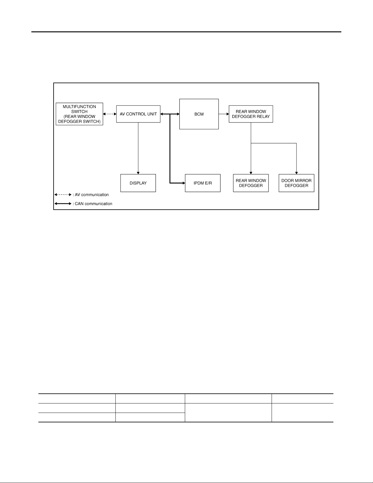
REAR WINDOW DEFOGGER SYSTEM
2007 G35 Sedan
Revision: October 2006
< FUNCTION DIAGNOSIS >
FUNCTION DIAGNOSIS
REAR WINDOW DEFOGGER SYSTEM
System Diagram INFOID:0000000000962679
JMLIA0005GB
System Description INFOID:0000000000962680
Operation Description
• Turn rear window defogger switch ON when the ignition switch is turned ON. Then malfunction switch (rear
window defogger switch) transmits rear window defogger switch signal to AV control unit via AV communication. AV control unit transmits rear window defogger switch signal to BCM via CAN communication.
• BCM turns rear window defogger relay ON when rear defogger switch signal is received.
• Rear window defogger and door mirror defogger (with mirror defogger) are supplied with power and operate
when rear window defogger relay turns ON.
• BCM transmits rear window defogger control signal to AV control unit via CAN communication when rear
window defogger operates.
• Rear window defogger ON is displayed when AV control unit receives signals.
The indicator of the rear window defogger switch also turns ON when rear defogger control signal is transmitted to multifunction switch (rear window defogger switch) with A V communication.
Timer function
• BCM turns rear window defogger relay ON for approximately 15 minutes when rear window defogger switch
is turned ON while ignition switch is ON. It makes rear window defogger and door mirror defogger (with mirror defogger) operate.
• Timer is canceled af ter pressing rear window defogger switch again during timer operation. Then BCM turns
rear window defogger relay OFF. The same reaction also occurs during timer operation, if the ignition switch
is turned OFF.
INPUT/OUTPUT SIGNAL CHART
Rear window defogger switch Defogger switch signal
Push button ignition swit ch Ignition signal
*: With mirror defogger
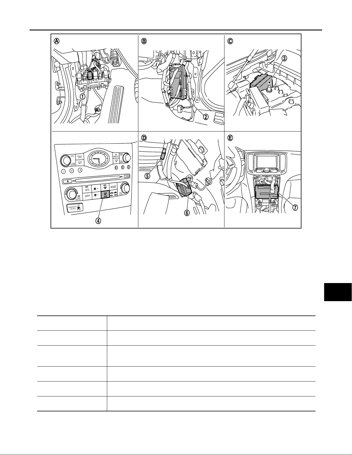
Component Parts Location INFOID:0000000000962681
Switch Input signal to BCM BCM function Acutuator
Rear window defogger & Door mir-
ror defogger
*
control
Rear window defogger
Door mirror defogger
DEF-4
*
Page 5
< FUNCTION DIAGNOSIS >
2007 G35 Sedan
Revision: October 2006
REAR WINDOW DEFOGGER SYSTEM
A
B
C
D
E
F
G
JMLIA0003ZZ
1. Rear window defogger relay 2. BCM M118, M119, M122, M123 3. IPDM E/R E6
Rear window defogger switch (built in
4.
multifunction switch M72)
AV control unit
7.
With NAVI M87,M88
Without NAVI M83, M85
A. Dash side lower (driver side) B. Dash side lower (passenger side) C. Engine room dash panel (RH)
D. Behind rear pillar finisher( LH ) E. Behind cluster lid C
5. Rear window defogger B401, B402 6. Condenser B26
Component Description INFOID:0000000000962682
BCM
Rear window defogger relay
Multfunction switch
(Rear window defogger
switch)
AV control unit
Rear window defogger
Door mirror defogger
*:
With mirror defogger
*
• Operates the rear window defogger with the operation of rear window defogger switch.
• Performs the timer control of rear window defogger.
• Operates the rear window defogger and the door mirror defogger with the control signal from
BCM.
• The rear window defogger switch is installed.
• Turns the indicator lamp ON when detecting the operation of rear window defogger.
• Displays the rear window defogger ON to the display when detecting t he operation of rear win dow defogger.
• Heats the heating wire with the power supply from the rear window defogger relay to prevent
the rear window from fogging up.
• Heats the heating wire with the power supply from the rear window defogger relay to prevent
the door mirror from fogging up.
H
I
J
K
DEF
M
N
O
P
DEF-5
Page 6

DIAGNOSIS SYSTEM (BCM)
2007 G35 Sedan
Revision: October 2006
< FUNCTION DIAGNOSIS >
DIAGNOSIS SYSTEM (BCM)
COMMON ITEM
COMMON ITEM : CONSULT-III Function (BCM - COMMON ITEM) INFOID:0000000000962683
APPLICATION ITEM
CONSULT-III performs the following functions via CAN communication with BCM.
Diagnosis mode Function Description
WORK SUPPORT Changes the setting for each system function.
SELF-DIAG RESULTS Displays the diagnosis results judged by BCM. Refer to BCS-74, "
CAN DIAG SUPPORT MNTR Monitors the reception status of CAN communication viewed from BCM.
DATA MONITOR The BCM input/output signals are displayed.
ACTIVE TEST The signals used to activate each device are forcibly supplied from BCM.
ECU IDENTIFICATION Th e BCM part number is displayed.
CONFIGURATION This function is not used even though it is displayed.
SYSTEM APPLICATION
BCM can perform the following functions for each system.
NOTE:
It can perform the diagnosis modes except the following for all sub system selection items.
DTC Index".
System Sub system selection item
Door lock DOOR LOCK ×××
Rear window defogger REAR DEFOGGER ××
Warning chime BUZZER ××
Interior room lamp timer INT LAMP ×××
Exterior lamp HEAD LAMP ×××
Wiper and washer WIPER ×××
Turn signal and haza rd warning lamp s FLASHER ×××
Air conditioner* AIR CONDITONER ×
Intelligent Key system INTELLIGENT KEY ×××
Combination switch COMB SW ×
BCM BCM ×
IVIS - NATS IMMU ××
Interior room lamp battery saver BATTERY SAVER ×××
Trunk open TRUNK ×
Vehicle security system THEFT ALM ×××
RAP system RETAINED PWR ×
Signal buffer system SIGNAL BUFFE R ××
TPMS
*: This item is displayed, but is not used.
TPMS (AIR PRESSURE MONITOR)
WORK SUPPORT DATA MONITOR ACTIVE TEST
×××
Diagnosis mode
REAR WINDOW DEFOGGER
REAR WINDOW DEFOGGER : CONSULT-III Function (BCM - REAR DEFOGGER)
Data monitor
INFOID:0000000000962684
DEF-6
Page 7

< FUNCTION DIAGNOSIS >
2007 G35 Sedan
Revision: October 2006
DIAGNOSIS SYSTEM (BCM)
Monitor Item Description
REAR DEF SW This is displayed even when it is not equipped.
PUSH SW Indicates [ON/OFF] condition of push switch.
ACTIVE TEST
Test Item Description
REAR DEFOGGER
This test is able to check rear window defogger operation. Rear window defogger operates when
“ON” on CONSULT-III screen is touched.
A
B
C
D
E
F
G
H
I
J
K
DEF
M
N
O
P
DEF-7
Page 8

REAR WINDOW DEFOGGER SWITCH
2007 G35 Sedan
Revision: October 2006
< COMPONENT DIAGNOSIS >
COMPONENT DIAGNOSIS
REAR WINDOW DEFOGGER SWITCH
Description INFOID:0000000000962685
• The rear window defogger is operated by turning the rear window defogger switch ON.
• Turns the indicator lamp in the rear window defogger switch ON when operating the rear window defogger.
Component Function Check INFOID:0000000000962686
1.CHECK REAR WINDOW DEFOGGER SWITCH FUNCTION
Check that the indicator lamp of rear window defogger illuminates when rear window defogger switch ON.
Is the inspection result normal?
YES >> Rear window defogger switch function is OK.
NO >> Refer to DEF-8, "
Diagnosis Procedure INFOID:0000000000962687
1.CHECK MULTIFUNCTION SWITCH (REAR WINDOW DEFOGGER SWITCH)
Does malfunction switch operate normally?
Base audio without navigation. Refer to AV-19, "
Bose audio without navigation. Refer to AV-138, "
Bose audio with navigation. Refer to AV-333, "
Is the inspection result normal?
YES >> INSPECTION END.
NO >> Replace multifunction switch (rear window defogger switch). Refer toAV-541, "
Installation".
Diagnosis Procedure".
Diagnosis Description".
Diagnosis Description".
Diagnosis Description".
Removal and
DEF-8
Page 9

REAR WINDOW DEFOGGER RELAY
2007 G35 Sedan
Revision: October 2006
< COMPONENT DIAGNOSIS >
REAR WINDOW DEFOGGER RELAY
Description INFOID:0000000000962688
Power is supplied to the rear window defogger with BCM control.
Component Function Check INFOID:0000000000962689
1.CHECK REAR WINDOW DEFOGGER RELAY POWER SUPPLY CIRCUIT
Check that an operation noise of rear window defogger relay can be heard when turning the rear window
defogger switch ON.
Is the inspection result normal?
YES >> Rear window defogger relay power supply circuit is OK.
NO >> Refer to DEF-9, "
Diagnosis Procedure".
Diagnosis Procedure INFOID:0000000000962690
1.CHECK REAR WINDOW DEFOGGER RELAY GROUND CIRCUIT
1. Turn ignition switch ON.
2. Check voltage between BCM connector and ground.
Terminals
(+)
BCM connector Terminal
M123 151 Ground
Is the inspection result normal?
YES >> Rear window defogger power supply circuit is OK.
NO >> GO TO 2.
(–)
Condition of rear window defog-
ger switch
ON 0
OFF Battery voltage
Voltage (V)
(Approx.)
2.CHECK HARNESS CONTINUITY
A
B
C
D
E
F
G
H
I
J
1. Turn ignition switch OFF.
2. Disconnect BCM connector and rear window defogger relay.
3. Check continuity between BCM connector and rear window defogger relay connector.
BCM connector Terminal Fuse block (J/B) connector T erminal Continuity
M123 151 M2 4B Existed
Is the inspection result normal?
YES >> GO TO 3.
NO >> Repair or replace harness.
3.CHECK REAR WINDOW DEFOGGER RELAY
Check rear window defogger relay.
Refer to DEF-10, "
Is the inspection result normal?
YES >> GO TO 4.
NO >> Replace rear window defogger relay.
Component Inspection".
4.CHECK INTERMITTENT INCIDENT
Check intermittent incident.
Refer to GI-39, "
Is the inspection result normal?
YES >> Check the following.
Intermittent Incident"
• Batter power supply circuit.
• Fuse block (J/B).
K
DEF
M
N
O
P
DEF-9
Page 10
REAR WINDOW DEFOGGER RELAY
2007 G35 Sedan
Revision: October 2006
< COMPONENT DIAGNOSIS >
NO >> Repair or replace the malfunctioning parts.
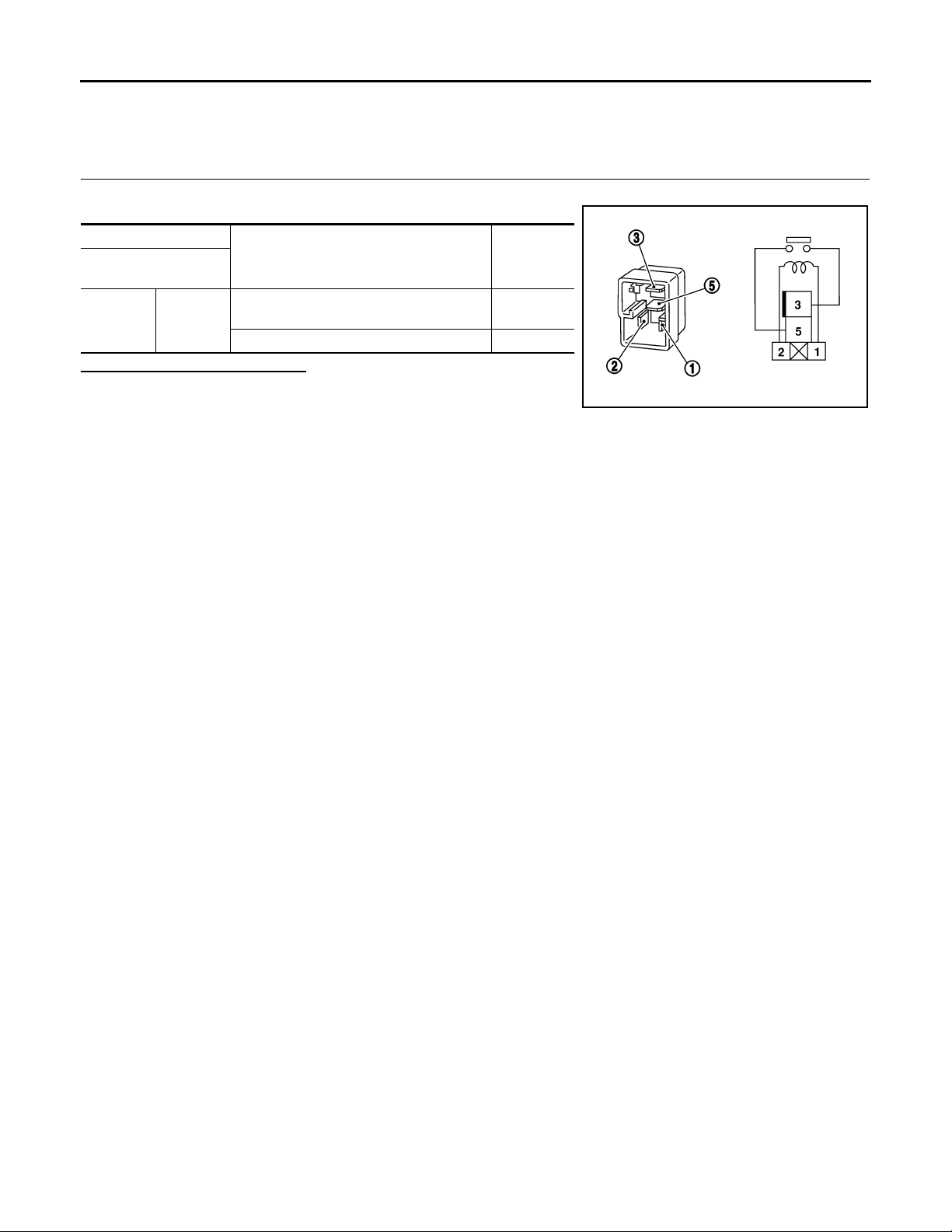
Component Inspection INFOID:0000000000962691
1.CHECK REAR WINDOW DEFOGGER RELAY
Check rear window defogger relay.
Terminal
Rear window
defogger relay
12V direct current supply between termi-
35
nals 1 and 2.
No current supply Not existed
Is the inspection result normal?
YES >> INSPECTION END.
NO >> Replace rear window defogger relay.
Condition Continuity
Existed
SEF497Y
DEF-10
Page 11

REAR WINDOW DEFOGGER POWER SUPPLY AND GROUND CIRCUIT
2007 G35 Sedan
Revision: October 2006
< COMPONENT DIAGNOSIS >
REAR WINDOW DEFOGGER POWER SUPPLY AND GROUND CIRCUIT
Description INFOID:0000000000962692
Heats the heating wire with the power supply from the rear window defogger relay to prevent the rear window
from fogging up.
Component Function Check INFOID:0000000000962693
1.CHECK REAR WINDOW DEFOGGER
Check that the heating wire of rear window defogger is heated when turning the rear window defogger switch
ON.
Is the inspection result normal?
YES >> Rear window defogger is OK.
NO >> Refer to DEF-11, "
Diagnosis Procedure".
Diagnosis Procedure INFOID:0000000000962694
1.CHECK POWER SUPPLY CIRCUIT
1. Turn ignition switch ON.
2. Check voltage between rear window defogger connector and ground.
Terminals
(+)
Rear window defogger
connector
B401 1 Ground
Is the inspection result normal?
YES >> GO TO 2.
NO >> GO TO 3.
Terminal
(–)
Condition of rear window
defogger switch
ON Battery voltage
OFF 0
Voltage (V)
(Approx.)
2.CHECK GROUND CIRCUIT
A
B
C
D
E
F
G
H
I
J
K
1. Turn ignition switch OFF.
2. Disconnect rear window defogger connector.
3. Check continuity between rear window defogger connector and ground.
Rear window defogger connector Terminal
Is the inspection result normal?
YES >> GO TO 5.
NO >> Repair or replace harness between rear window defogger and ground.
3.CHECK HARNESS CONTINUITY 1
1. Turn ignition switch OFF.
2. Disconnect condenser and rear window defogger connectors.
3. Check continuity between condenser and rear window defogger connector.
Condenser connector Terminal Rear window defogger connector Terminal Continuity
Is the inspection result normal?
YES >> GO TO 4.
NO >> Replace condenser.Refer to DEF-61, "
B402 2 Existed
B26 1 B401 1 Existed
Removal and Installation".
Ground
Continuity
DEF-11
DEF
M
N
O
P
Page 12

REAR WINDOW DEFOGGER POWER SUPPLY AND GROUND CIRCUIT
2007 G35 Sedan
Revision: October 2006
< COMPONENT DIAGNOSIS >
4.CHECK HARNESS CONTINUITY 2
1. Remove rear window defogger relay.
2. Check continuity between rear window defogger relay connector and condenser connector.
Fuse block (J/B) connector Terminal Condenser connector Terminal Continuity
B6
Is the inspection result normal?
YES >> GO TO 6.
NO >> Replace or repair harness between fuse block(J/B) and condenser.
10G
11G
B26 1 Existed
5.CHECK FILAMENT
Check filament.
Refer to DEF-12, "
Is the inspection result normal?
YES >> Refer to GI-39, "Intermittent Incident".
NO >> Repair filament.
Component Inspection".
6.CHECK INTERMITTENT INCIDENT
Check intermittent incident.
Refer to GI-39, "
Is the inspection result normal?
YES >> Check the following.
NO >> Repair or replace the malfunctioning parts.
Intermittent Incident".
• Batter power supply circuit.
• Fuse block (J/B).
Component Inspection INFOID:0000000000962695
1.CHECK FILAMENT
Check the filament for damage or blown.
Refer to DEF-59, "
Is the inspection result normal?
YES >> INSPECTION END.
NO >> Repair filament.
Inspection and Repair".
DEF-12
Page 13

DRIVER SIDE DOOR MIRROR DEFOGGER
2007 G35 Sedan
Revision: October 2006
< COMPONENT DIAGNOSIS >
DRIVER SIDE DOOR MIRROR DEFOGGER
Description INFOID:0000000000962696
Heats the heating wire with the power supply from the rear window defogger relay to prevent the door mirror
from fogging up.
Component Function Check INFOID:0000000000962697
1.CHECK DRIVER SIDE DOOR MIRROR DEFOGGER
Check that heating wire of driver side door mirror defogger is heated when turning the rear window defogger
switch ON.
Is the inspection result normal?
YES >> Driver side door mirror defogger is OK.
NO >> Refer to DEF-13, "
Diagnosis Procedure".
Diagnosis Procedure INFOID:0000000000962698
1.CHECK POWER SUPPLY CIRCUIT
1. Turn ignition switch OFF.
2. Disconnect door mirror (driver side) connector.
3. Turn ignition switch ON.
4. Check voltage between door mirror (driver side) connector and ground.
Terminals
(+)
Door mirror (driver side) connector Terminal
D3 4 Ground
Is the inspection result normal?
YES >> GO TO 2.
NO >> Repair or replace harness between fuse block (J/B) and door mirror (driver side).
(–)
Condition of rear win-
dow defogger switch
ON Battery voltage
OFF 0
Voltage (V)
(Approx.)
2.CHECK GROUND CIRCUIT
A
B
C
D
E
F
G
H
I
J
K
1. Turn ignition switch OFF.
2. Check continuity between door mirror (driver side) connector and ground.
Door mirror (driver side) connector Terminal
Is the inspection result normal?
YES >> GO TO 3.
NO >> Repair or replace harness between door mirror (driver side) and ground.
3.CHECK DRIVER SIDE DOOR MIRROR DEFOGGER
Check driver side door mirror defogger.
Refer to DEF-14, "
Is the inspection result normal?
YES >> GO TO 4.
NO >> Replace door mirror (driver side). Refer to MIR-67, "
4.CHECK INTERMITTENT INCIDENT
Check intermittent incident.
Refer to GI-39, "
Is the inspection result normal?
YES >> Check the following.
D3 8 Existed
Component Inspection".
Intermittent Incident".
Ground
Removal and Installation".
Continuity
DEF-13
DEF
M
N
O
P
Page 14

DRIVER SIDE DOOR MIRROR DEFOGGER
2007 G35 Sedan
Revision: October 2006
< COMPONENT DIAGNOSIS >
• Batter power supply circuit.
• Fuse block (J/B).
NO >> Repair or replace the malfunctioning parts.
Component Inspection INFOID:0000000000962699
1.CHECK DRIVER SIDE DOOR MIRROR DEFOGGER
1. Turn ignition switch OFF.
2. Disconnect door mirror (driver side) connector.
3. Check continuity between door mirror terminals.
Door mirror (diver side) connector Terminal Continuity
D3 4 8 Existed
Is the inspection result normal?
YES >> INSPECTION END.
NO >> Replace door mirror (driver side). Refer to MIR-67, "
Removal and Installation".
DEF-14
Page 15

PASSENGER SIDE DOOR MIRROR DEFOGGER
2007 G35 Sedan
Revision: October 2006
< COMPONENT DIAGNOSIS >
PASSENGER SIDE DOOR MIRROR DEFOGGER
Description INFOID:0000000000962700
Heats the heating wire with the power supply from the rear window defogger relay to prevent the door mirror
from fogging up.
Component Function Check INFOID:0000000000962701
1.CHECK PASSENGER SIDE DOOR MIRROR DEFOGGER
Check that the heating wire of passenger side door mirror defogger is heated when turning the rear window
defogger switch ON.
Is the inspection result normal?
YES >> Passenger side door mirror defogger is OK.
NO >> Refer to DEF-15, "
Diagnosis Procedure".
Diagnosis Procedure INFOID:0000000000962702
1.CHECK POWER SUPPLY CIRCUIT
1. Turn ignition switch OFF.
2. Disconnect door mirror (passenger side) connector.
3. Turn ignition switch ON.
4. Check voltage between door mirror (passenger side) connector and ground.
Terminals
(+)
Door mirror (Passenger side) connec-
tor
D33 4 Ground
Is the inspection result normal?
YES >> GO TO 2.
NO >> Repair or replace harness between fuse block (J/B) and door mirror (passenger side).
Terminal
(–)
Condition of rear win-
dow defogger switch
ON Battery voltage
OFF 0
Voltage (V)
(Approx.)
2.CHECK GROUND CIRCUIT
A
B
C
D
E
F
G
H
I
J
K
1. Turn ignition switch OFF.
2. Check continuity between door mirror (passenger side) connector and ground.
Door mirror (passenger side)
Is the inspection result normal?
YES >> GO TO 3.
NO >> Repair or replace harness between door mirror (passenger side) and ground.
3.CHECK PASSENGER SIDE DOOR MIRROR DEFOGGER
Check passenger side door mirror defogger.
Refer to DEF-16, "
Is the inspection result normal?
YES >> GO TO 4.
NO >> Replace door mirror (passenger side).Refer to MIR-67, "
4.CHECK INTERMITTENT INCIDENT
Check intermittent incident.
Refer to GI-39, "
Is the inspection result normal?
connector
D33 8 Existed
Component Inspection".
Intermittent Incident".
Terminal
Ground
Removal and Installation".
DEF-15
Continuity
DEF
M
N
O
P
Page 16

PASSENGER SIDE DOOR MIRROR DEFOGGER
2007 G35 Sedan
Revision: October 2006
< COMPONENT DIAGNOSIS >
YES >> Check the following.
• Batter power supply circuit.
• Fuse block (J/B).
NO >> Repair or replace the malfunctioning parts.
Component Inspection INFOID:0000000000962703
1.CHECK PASSENGER DOOR MIRROR DEFOGGER
1. Turn ignition switch OFF.
2. Disconnect door mirror (passenger side) connector.
3. Check continuity between door mirror terminals.
Door mirror (passenger side) connector Terminal Continuity
D33 4 8 Existed
Is the inspection result normal?
YES >> INSPECTION END.
NO >> Replace door mirror (passenger side). Refer to MIR-67, "
Removal and Installation".
DEF-16
Page 17

< ECU DIAGNOSIS >
2007 G35 Sedan
Revision: October 2006
BCM (BODY CONTROL MODULE)
ECU DIAGNOSIS
BCM (BODY CONTROL MODULE)
Reference Value INFOID:0000000000962704
VALUES ON THE DIAGNOSIS TOOL
Monitor Item Condition Val ue/Status
FR WIPER HI
FR WIPER LOW
FR WASHER SW
FR WIPER INT
FR WIPER STOP
INT VOLUME Wiper intermittent dial is in a dial position 1 - 7 Wiper intermittent dial position
TURN SIGNAL R
TURN SIGNAL L
TAIL LAMP SW
HI BEAM SW
HEAD LAMP SW 1
HEAD LAMP SW 2
PASSING SW
AUTO LIGHT SW
FR FOG SW
RR FOG SW
DOOR SW-DR
DOOR SW-AS
DOOR SW-RR
Other than front wiper switch HI OFF
Front wiper switch HI ON
Other than front wiper switch LO OFF
Front wiper switch LO ON
Front washer switch OFF OFF
Front washer switch ON ON
Other than front wiper switch INT OFF
Front wiper switch INT ON
Front wiper is not in STOP position OFF
Front wiper is in STOP position ON
Other than turn signal switch RH OFF
Turn signal switch RH ON
Other than turn signal switch LH OFF
Turn signal switch LH ON
Other than lighting switch 1ST and 2ND OFF
Lighting switch 1ST or 2ND ON
Other than lighting switch HI OFF
Lighting switch HI ON
Other than lighting switch 2ND OFF
Lighting switch 2ND ON
Other than lighting switch 2ND OFF
Lighting switch 2ND ON
Other than lighting switch PASS OFF
Lighting switch PASS ON
Other than lighting switch AUTO OFF
Lighting switch AUTO ON
Front fog lamp switch OFF OFF
Front fog lamp switch ON ON
NOTE:
The item is indicated, but not monitored.
Driver door closed OFF
Driver door opened ON
Passenger door closed OFF
Passenger door opened ON
Rear RH door closed OFF
Rear RH door opened ON
OFF
A
B
C
D
E
F
G
H
I
J
K
DEF
M
N
O
P
DEF-17
Page 18

BCM (BODY CONTROL MODULE)
2007 G35 Sedan
Revision: October 2006
< ECU DIAGNOSIS >
Monitor Item Condition Value/Status
DOOR SW-RL
DOOR SW-BK
CDL LOCK SW
CDL UNLOCK SW
KEY CYL LK-SW
KEY CYL UN-SW
KEY CYL SW-TR
HAZARD SW
REAR DEF SW
H/L WASH SW
TR CANCEL SW
TR/BD OPEN SW
TRNK/HAT MNTR
RKE-LOCK
RKE-UNLOCK
RKE-TR/BD
RKE-PANIC
RKE-P/W OPEN
RKE-MODE CHG
OPTICAL SENSOR
REQ SW-DR
REQ SW-AS
Rear LH door closed OFF
Rear LH door opened ON
NOTE:
The item is indicated, but not monitored.
Other than power door lock switch LOCK OFF
Power door lock switch LOCK ON
Other than power door lock switch UNLOCK OFF
Power door lock switch UNLOCK ON
Other than driver door key cylinder LOCK position OFF
Driver door key cylinder LOCK position ON
Other than driver door key cylinder UNLOCK position OFF
Driver door key cylinder UNLOCK position ON
NOTE:
The item is indicated, but not monitored.
Hazard switch is not pressed OFF
Hazard switch is pressed ON
NOTE:
The item is indicated, but not monitored.
NOTE:
The item is indicated, but not monitored.
Trunk lid opener cancel switch OFF OFF
Trunk lid opener cancel switch ON ON
Trunk lid opener switch OFF OFF
While the trunk lid opener switch is turned ON ON
Trunk lid closed OFF
Trunk lid opened ON
LOCK button of Intelligent Key is not pressed OFF
LOCK button of Intelligent Key is pressed ON
UNLOCK button of Intelligent Key is not pressed OFF
UNLOCK button of Intelligent Key is pressed ON
TRUNK OPEN button of Intelligent Key is not pressed OFF
TRUNK OPEN button of Intelligent Key is pressed ON
PANIC button of Intelligent Key is not pressed OFF
PANIC button of Intelligent Key is pressed ON
UNLOCK button of Intelligent Key is not pressed OFF
UNLOCK button of Intelligent Key is pressed and held ON
LOCK/UNLOCK button of Intelligent Key is not pressed and held si-
multaneously
LOCK/UNLOCK button of Intelligent Key is pressed and held simul-
taneously
Outside of the vehicle bri ght Close to 5 V
Outside of the vehicle dark Close to 0 V
Driver door request switch is not pressed OFF
Driver door request switch is presse d ON
Passenger door request switch is not pressed OFF
Passenger door request switch is pressed ON
OFF
OFF
OFF
OFF
OFF
ON
DEF-18
Page 19

< ECU DIAGNOSIS >
2007 G35 Sedan
Revision: October 2006
BCM (BODY CONTROL MODULE)
Monitor Item Condition Val ue/Status
REQ SW-BD/TR
PUSH SW
IGN RLY2 -F/B
ACC RLY -F/B
CLUCH SW
BRAKE SW 1
DETE/CANCL SW
SFT PN/N SW
S/L -LOCK
S/L -UNLOCK
S/L RELAY-F/B
UNLK SEN-DR
PUSH SW -IPDM
IGN RLY1 -F/B
DETE SW -IPDM
SFT PN -IPDM
SFT P -MET
SFT N -MET
ENGINE STATE
S/L LOCK-IPDM
S/L UNLK-IPDM
Trunk request switch is not pressed OFF
Trunk request switch is pressed ON
Push-button ignition switch (push switch) is not pressed OFF
Push-button ignition switch (pus h switch) is pressed ON
Ignition switch in OFF or ACC position OFF
Ignition switch in ON position ON
Ignition switch in OFF position OFF
Ignition switch in ACC or ON position ON
The clutch pedal is not depressed OFF
The clutch pedal is depressed ON
The brake pedal is not depressed ON
The brake pedal is depressed OFF
Selector lever in P position OFF
Selector lever in any position other than P ON
Selector lever in any position other than P and N OFF
Selector lever in P or N position ON
Steering is locked OFF
Steering is unlocked ON
Steering is unlocked OFF
Steering is locked ON
Ignition switch is OFF or ACC position OFF
Ignition switch is ON position ON
Driver door is unlocked OFF
Driver door is locked ON
Push-button ignition switch (push-switch) is not pressed OFF
Push-button ignition switch (push-s witch) is pressed ON
Ignition switch is OFF or ACC position OFF
Ignition switch is ON position ON
Selector lever in P position OFF
Selector lever in any position other than P ON
Selector lever in any position other than P and N OFF
Selector lever in P or N position ON
Selector lever in any position other than P OFF
Selector lever in P position ON
Selector lever in any position other than N OFF
Selector lever in N position ON
Engine stopped STOP
While the engine stalls STALL
At engine cranking CRANK
Engine running RUN
Steering is locked OFF
Steering is unlocked ON
Steering is unlocked OFF
Steering is locked ON
A
B
C
D
E
F
G
H
I
J
K
DEF
M
N
O
P
DEF-19
Page 20

BCM (BODY CONTROL MODULE)
2007 G35 Sedan
Revision: October 2006
< ECU DIAGNOSIS >
Monitor Item Condition Value/Status
S/L RELAY-REQ
VEH SPEED 1 While driving Equivalent to speedometer reading
VEH SPEED 2 While driving Equivalent to speedometer reading
DOOR STAT-DR
DOOR STAT-AS
ID OK FLAG
PRMT ENG STRT
PRMT RKE STRT
KEY SW -SLOT
RKE OPE COUN1 During the operation of Intelligent Key Operation frequency of Intelligent Key
RKE OPE COUN2
AIR PRESS FL
AIR PRESS FR
AIR PRESS RR
AIR PRESS RL
ID REGST FL1
ID REGST FR1
ID REGST RR1
ID REGST RL1
WARNING LAMP
BUZZER
Ignition switch in OFF or ACC position OFF
Ignition switch in ON position ON
Driver door is locked LOCK
Wait with selective UNLOCK operation (5 seconds) READY
Driver door is unlocked UNLK
Passenger door is locked LOCK
Wait with selective UNLOCK operation (5 seconds) READY
Passenger door is unlocked UNLK
Ignition switch in ACC or ON position RESET
Ignition switch in OFF position SET
The engine start is prohibited RESET
The engine start is permitted SET
NOTE:
The item is indicated, but not monitored.
Intelligent Key is not inserted into key slot OFF
Intelligent Key is inserted into key slot ON
NOTE:
The item is indicated, but not monitored.
Ignition switch ON (Only when the signal from the transmitter is re-
ceived)
Ignition switch ON (Only when the signal from the transmitter is re-
ceived)
Ignition switch ON (Only when the signal from the transmitter is re-
ceived)
Ignition switch ON (Only when the signal from the transmitter is re-
ceived)
ID of front LH tire transmitter is registered DONE
ID of front LH tire transmitter is not registered YET
ID of front RH tire transmitter is registered DONE
ID of front RH tire transmitter is not registered YET
ID of rear RH tire transmitter is registered DONE
ID of rear RH tire transmitter is not registered YET
ID of rear LH tire transmitter is registered DONE
ID of rear LH tire transmitter is not registered YET
Tire pressure indicator OFF OFF
Tire pressure indicator ON ON
Tire pressure warning alarm is not sounding OFF
Tire pressure warning alarm is sounding ON
RESET
Air pressure of front LH tire
Air pressure of front RH tire
Air pressure of rear RH tire
Air pressure of rear LH tire
—
DEF-20
Page 21
< ECU DIAGNOSIS >
2007 G35 Sedan
Revision: October 2006
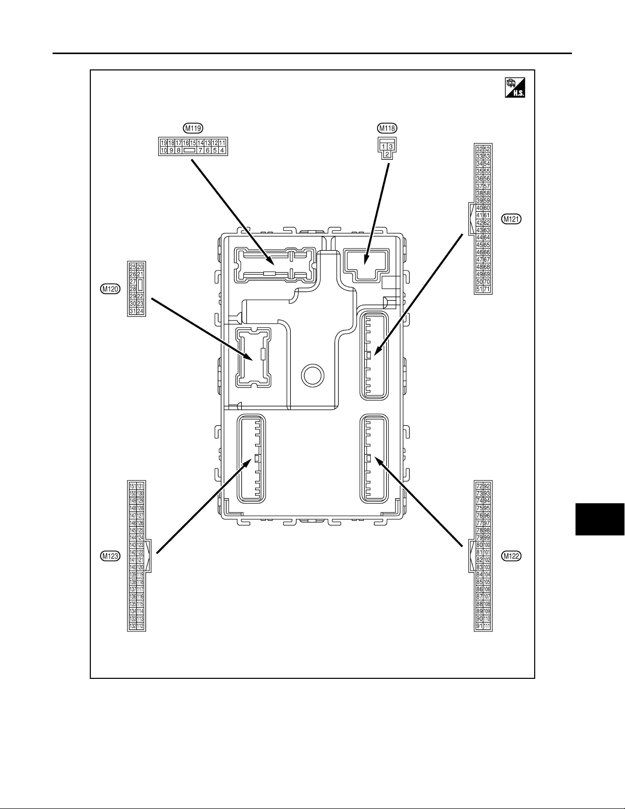
TERMINAL LAYOUT
BCM (BODY CONTROL MODULE)
A
B
C
D
E
F
G
H
I
J
K
DEF
M
N
O
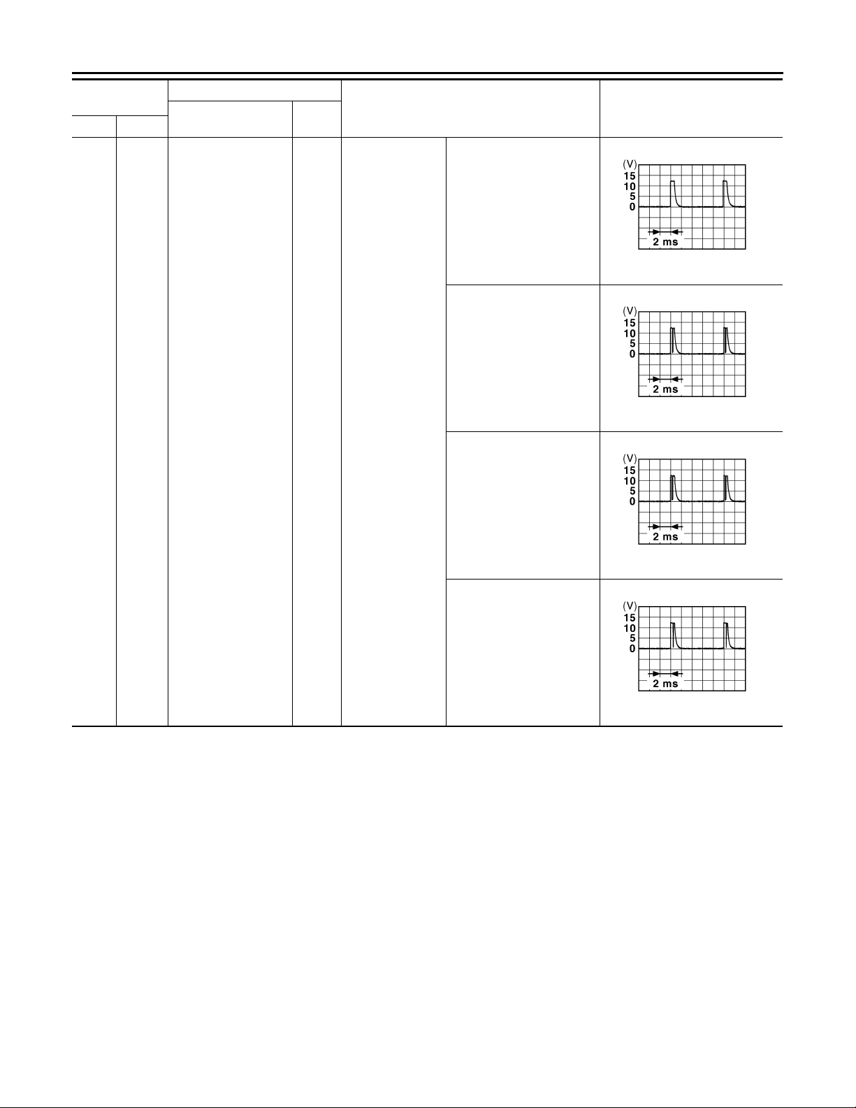
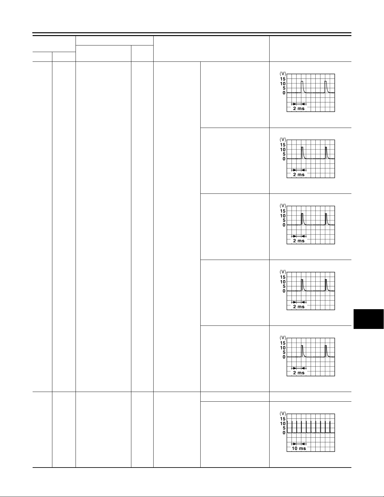
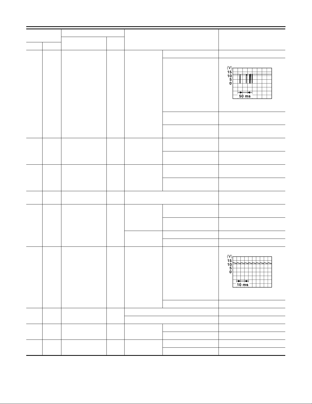
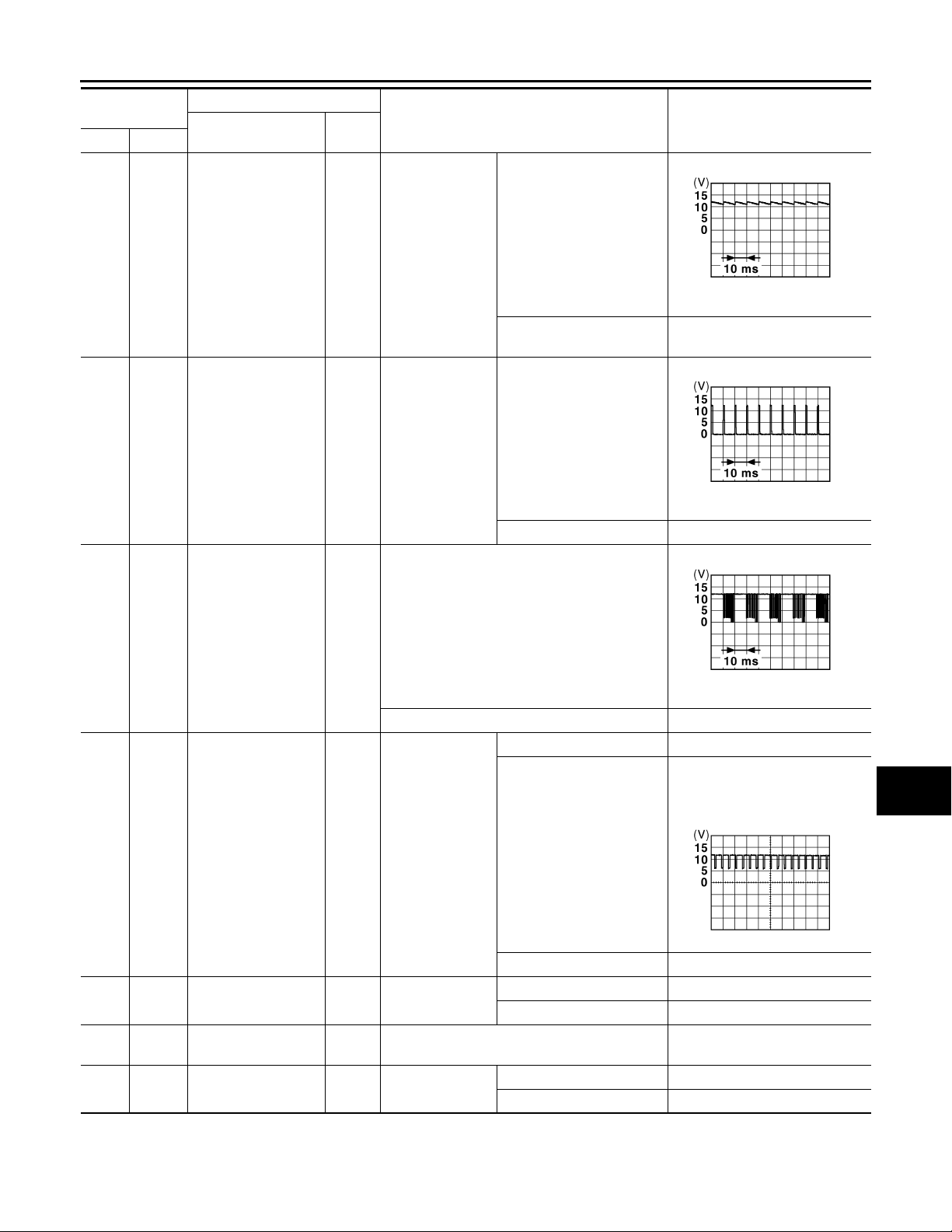
PHYSICAL VALUES
JPMIA0062ZZ
P
DEF-21
Page 22
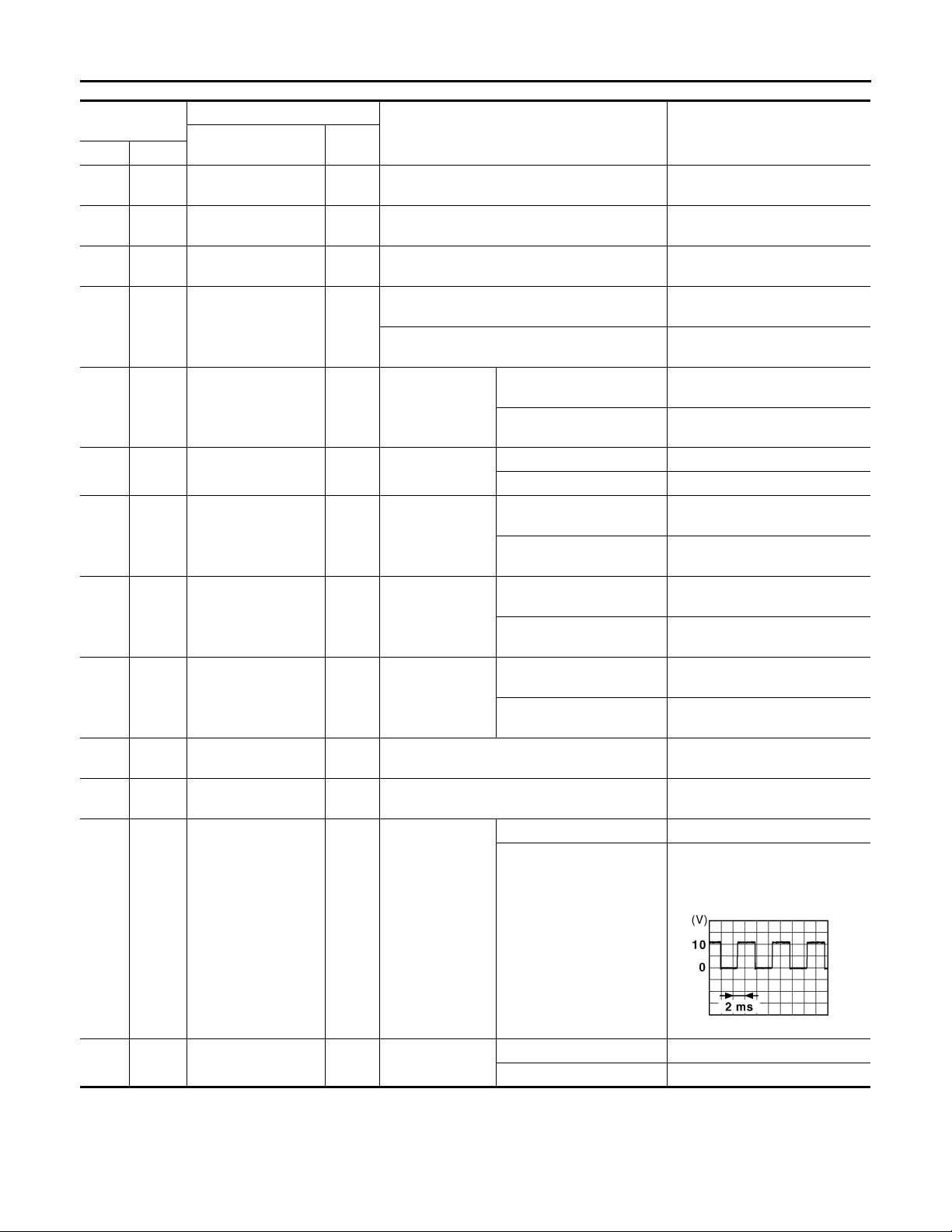
< ECU DIAGNOSIS >
2007 G35 Sedan
Revision: October 2006
BCM (BODY CONTROL MODULE)
Terminal No.
(Wire color)
1
Ground Battery power supply Input Ignition switch OFF Battery voltage
(W)
2
Ground
(Y)
3
Ground
(O)
4
Ground
(LG)
5
Ground
(V)
7
Ground Step lamp Output Step lamp
(Y)
8
Ground
(V)
9
Ground
(G)
10
Ground
(BR)
11
Ground Battery power supply Input Ignition switch OFF Battery voltage
(R)
13
Ground Ground — Ignition switch ON 0 V
(B)
14
Ground
(W)
P/W power supply
(BAT)
P/W power supply
(RAP)
Interior room lamp
power supply
Passenger door UNLOCK
All doors, fuel lid
LOCK
Driver door, fuel lid
UNLOCK
Rear RH door and
rear LH door UNLOCK
Push-button ignition
switch illumination
ground
Description
Signal name
Input/
Output+–
Output Ignition switch OFF Battery voltage
Output Ignition switch ON Battery voltage
After passing the interior room lamp battery sav-
Output
Output Passenger door
Output All doors, fuel lid
Output
Output
Output Tail lamp
er operation time
Any other time after passi ng the interior room
lamp battery saver operation time
Driver door, fuel
lid
Rear RH door
and rear LH door
Condition
UNLOCK (Actuator is activated)
Other than UNLOCK (Actuator is not activated)
ON 0 V
OFF Battery voltage
LOCK (Actuator is activat-
ed)
Other than LOCK (Actuator
is not activated)
UNLOCK (Actuator is acti-
vated)
Other than UNLOCK (Actu-
ator is not activated)
UNLOCK (Actuator is acti-
vated)
Other than UNLOCK (Actu-
ator is not activated)
OFF 0 V
ON
Value
(Approx.)
0 V
Battery voltage
Battery voltage
0 V
Battery voltage
0 V
Battery voltage
0 V
Battery voltage
0 V
NOTE:
When the illumination brightening/dimming level is in the neutral
position
15
Ground ACC indicator lamp Output Ignition switch
(Y)
JSNIA0010GB
OFF Battery voltage
ACC or ON 0 V
DEF-22
Page 23
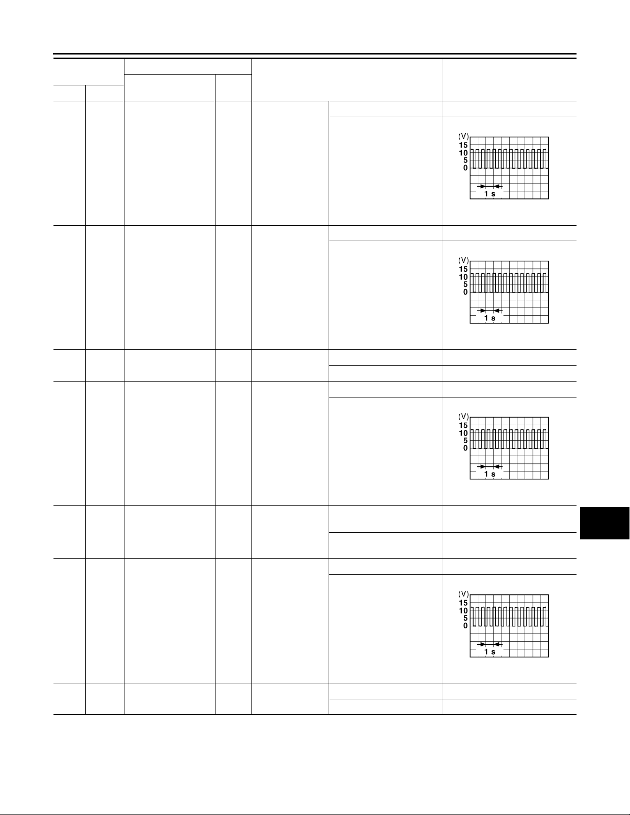
< ECU DIAGNOSIS >
2007 G35 Sedan
Revision: October 2006
BCM (BODY CONTROL MODULE)
Terminal No.
(Wire color)
17
Ground T urn signal (front RH) Output
(W)
18
Ground Turn signal (front LH) Output
(O)
19
(V)
Ground
Room lamp timer
control
Description
Signal name
Input/
Output+–
Output
Ignition switch
ON
Ignition switch
ON
Interior room
lamp
Condition
Turn signal switch OFF 0 V
Turn signal switch RH
Turn signal switch OFF 0 V
Turn signal switch LH
OFF Battery voltage
ON 0 V
Turn signal switch OFF 0 V
Value
(Approx.)
6.5 V
6.5 V
PKID0926E
PKID0926E
A
B
C
D
E
F
G
H
I
20
Ground Turn signal (rear RH) Output
(V)
23
Ground Trunk lid opening. Output Trunk lid
(G)
25
Ground Turn signal (rear LH) Output
(G)
30
Ground Trunk room lamp Output Trunk room lamp
(R)
Ignition switch
ON
Ignition switch
ON
Turn signal switch RH
Open (Trunk lid opener actuator is activated)
Close (Trunk lid open er a ctuator is not activated)
Turn signal switch OFF 0 V
Turn signal switch LH
ON 0 V
OFF Battery voltage
Battery voltage
0 V
6.5 V
6.5 V
PKID0926E
PKID0926E
J
K
DEF
M
N
O
P
DEF-23
Page 24
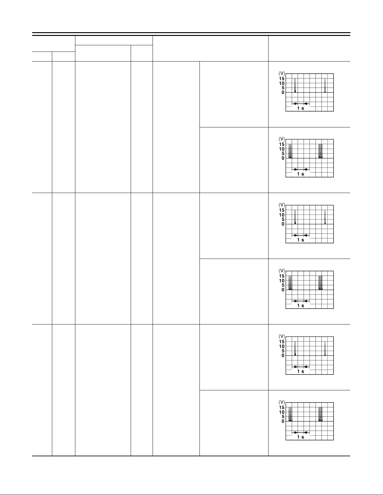
< ECU DIAGNOSIS >
B
B
B
B
B
B
2007 G35 Sedan
Revision: October 2006
BCM (BODY CONTROL MODULE)
Terminal No.
(Wire color)
34
Ground
(SB)
Description
Signal name
Trunk room antenna
1 (-)
Input/
Output+–
Output
Ignition switch
OFF
Condition
When Intelligent Key is in
the passenger compartment
When Intelligent Key is not
in the passenger compartment
When Intelligent Key is in
the passenger compartment
Value
(Approx.)
JMKIA0062G
JMKIA0063G
35
(V)
38
(B)
Ground
Ground
Trunk room antenna
1 (+)
Rear bumper antenna (-)
Output
Output
Ignition switch
OFF
When the trunk
lid request switch
is operated with
ignition switch
OFF
JMKIA0062G
When Intelligent Key is not
in the passenger compartment
JMKIA0063G
When Intelligent Key is in
the antenna detection area
JMKIA0062G
When Intelligent Key is not
in the antenna detection
area
JMKIA0063G
DEF-24
Page 25
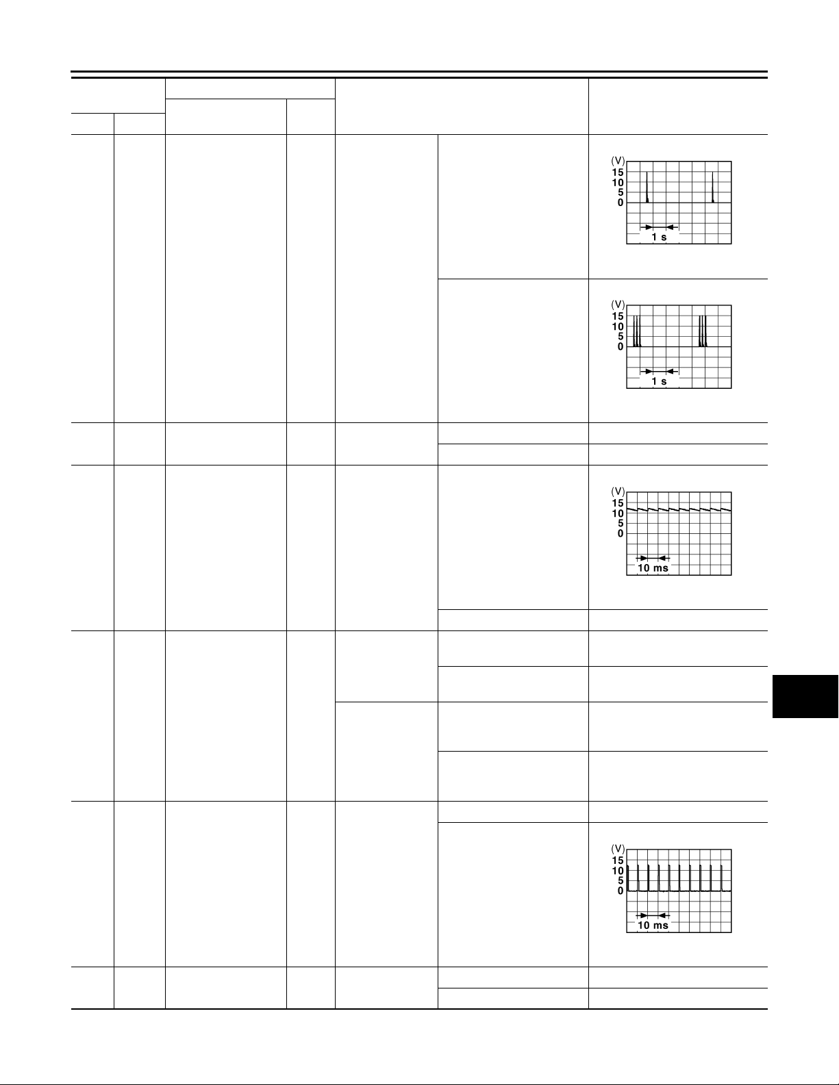
< ECU DIAGNOSIS >
B
B
B
2007 G35 Sedan
Revision: October 2006
BCM (BODY CONTROL MODULE)
Terminal No.
(Wire color)
39
Ground
(W)
47
Ground
(Y)
Description
Signal name
Rear bumper antenna (+)
Ignition relay (IPDM
E/R) control
Input/
Output+–
When the trunk
Output
Output Ignition switch
lid request switch
is operated with
ignition switch
OFF
Condition
When Intelligent Key is in
the antenna detection area
When Intelligent Key is not
in the antenna detection
area
OFF or ACC Battery voltage
ON 0 V
Value
(Approx.)
A
B
C
JMKIA0062G
D
E
F
JMKIA0063G
G
H
50
Ground
(R)
52
Ground Starter relay control Output
(SB)
61
Ground Trunk request switch Input
(W)
Trunk room lamp
switch
Input
Trunk room l amp
switch
Ignition switch
OFF (M/T models)
Ignition switch
ON (A/T models)
Trunk request
switch
OFF (Trunk is closed)
ON (Trunk is open) 0 V
When the clutch pedal is
depressed
When the clutch pedal is
not depressed
When selector lever is in P
or N position and the brake
is depressed
When selector lever is in P
or N position and the brake
is not depressed
ON (Pressed) 0 V
OFF (Not pressed)
Battery voltage
0 V
Battery voltage
0 V
11.8 V
JPMIA0011GB
I
J
K
DEF
M
N
O
P
64
Ground
(V)
Request switch buzzer
Output
Request switch
buzzer
DEF-25
JPMIA0016G
1.0 V
Sounding 0 V
Not sounding Battery voltage
Page 26
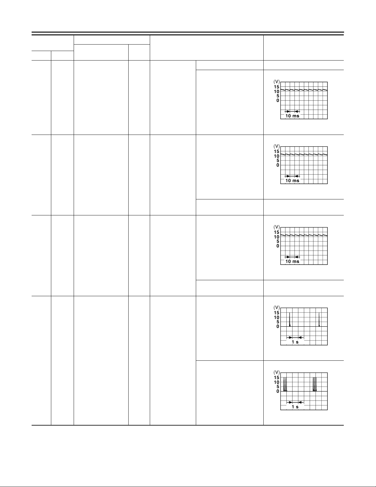
< ECU DIAGNOSIS >
B
B
2007 G35 Sedan
Revision: October 2006
BCM (BODY CONTROL MODULE)
Terminal No.
Description
(Wire color)
Signal name
67
Ground
(GR)
68
Ground Rear RH door switch Input
(BR)
Trunk lid opener
switch
Input/
Output+–
Input
Trunk lid opener
switch
Rear RH door
switch
Condition
Pressed 0 V
Not pressed
OFF (When rear RH door
closes)
ON (When rear RH door
opens)
Value
(Approx.)
JPMIA0011GB
11.8 V
JPMIA0011GB
11.8 V
0 V
69
Ground Rear LH door switch Input
(R)
72
(R)
Ground
Room antenna 2 (-)
(center console)
Output
Rear LH door
switch
Ignition switch
OFF
OFF (When rear LH door
closes)
ON (When rear LH door
opens)
When Intelligent Key is in
the passenger compartment
When Intelligent Key is not
in the passenger compartment
JPMIA0011GB
11.8 V
0 V
JMKIA0062G
JMKIA0063G
DEF-26
Page 27
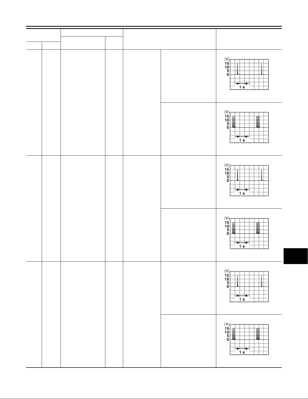
< ECU DIAGNOSIS >
B
B
B
B
B
B
2007 G35 Sedan
Revision: October 2006
BCM (BODY CONTROL MODULE)
Terminal No.
(Wire color)
73
Ground
(G)
Description
Signal name
Room antenna 2 (+)
(center console)
Input/
Output+–
Output
Ignition switch
OFF
Condition
When Intelligent Key is in
the passenger compartment
When Intelligent Key is not
in the passenger compartment
When Intelligent Key is in
the antenna detection area
Value
(Approx.)
A
B
C
JMKIA0062G
D
E
F
JMKIA0063G
G
H
74
(SB)
75
(BR)
Ground
Ground
Passenger door antenna (-)
Passenger door antenna (+)
Output
Output
When the passenger door request switch is
operated with ignition switch OFF
When the passenger door request switch is
operated with ignition switch OFF
When Intelligent Key is not
in the antenna detection
area
When Intelligent Key is in
the antenna detection area
When Intelligent Key is not
in the antenna detection
area
JMKIA0062G
JMKIA0063G
JMKIA0062G
I
J
K
DEF
M
N
O
P
JMKIA0063G
DEF-27
Page 28
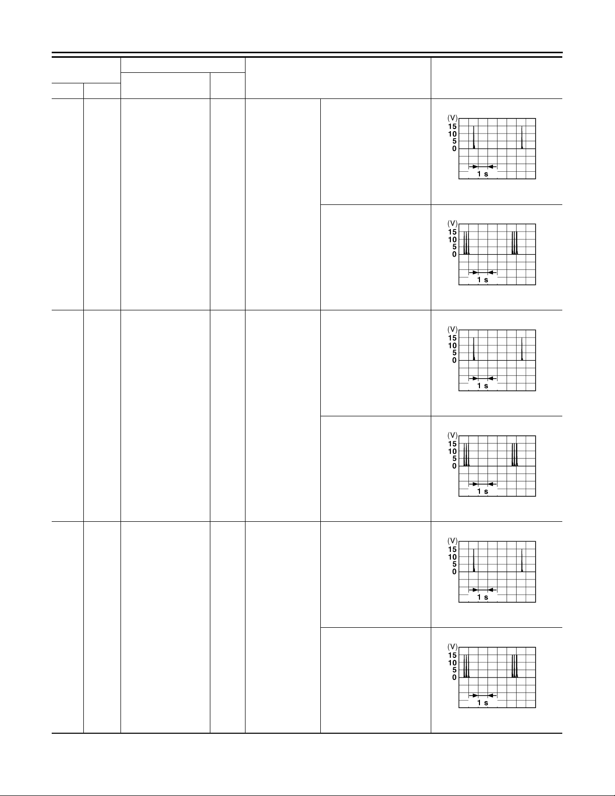
< ECU DIAGNOSIS >
B
B
B
B
B
B
2007 G35 Sedan
Revision: October 2006
BCM (BODY CONTROL MODULE)
Terminal No.
(Wire color)
76
Ground
(V)
Description
Signal name
Driver door antenna
(-)
Input/
Output+–
Output
When the driver
door request
switch is operated with ignition
switch OFF
Condition
When Intelligent Key is in
the antenna detection area
When Intelligent Key is not
in the antenna detection
area
Value
(Approx.)
JMKIA0062G
JMKIA0063G
77
(LG)
78
(Y)
Ground
Ground
Driver door antenna
(+)
Room antenna (-) (instrument panel)
Output
Output
When the driver
door request
switch is operated with ignition
switch OFF
Ignition switch
OFF
When Intelligent Key is in
the antenna detection area
JMKIA0062G
When Intelligent Key is not
in the antenna detection
area
JMKIA0063G
When Intelligent Key is in
the passenger compartment
JMKIA0062G
When Intelligent Key is not
in the passenger compartment
JMKIA0063G
DEF-28
Page 29
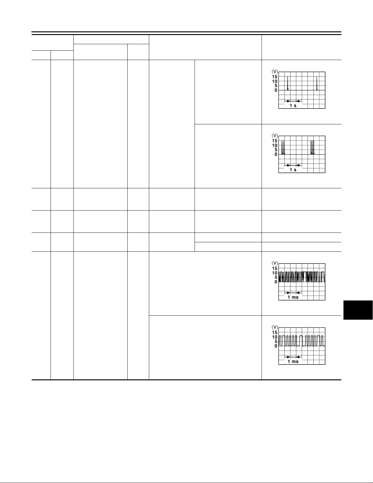
< ECU DIAGNOSIS >
B
B
B
B
2007 G35 Sedan
Revision: October 2006
BCM (BODY CONTROL MODULE)
Terminal No.
(Wire color)
79
Ground
(BR)
80
Ground
(GR)
81
Ground
(W)
82
Ground
(R)
Description
Signal name
Room antenna (+)
(instrument panel)
NATS antenna amp
(built in key slot)
NATS antenna amp
(built in key slot)
Ignition relay (relay
box) control
Input/
Output+–
Output
Input/
Output
Input/
Output
Output Ignition switch
Ignition switch
OFF
During waiting
During waiting
Condition
When Intelligent Key is in
the passenger compartment
When Intelligent Key is not
in the passenger compartment
Ignition switch is pressed
while inserting the Intelligent Key into the key slot.
Ignition switch is pressed
while inserting the Intelligent Key into the key slot.
OFF or ACC 0 V
ON Battery voltage
Just after pressing ignition
switch. Pointer of tester should
move.
Just after pressing ignition
switch. Pointer of tester should
move.
Value
(Approx.)
A
B
C
JMKIA0062G
D
E
F
JMKIA0063G
G
H
I
83
(Y)
Ground
Remote keyless entry
receiver signal
Input/
Output
During waiting
When operating either button on Intelligent Key
J
K
JMKIA0064G
DEF
M
N
JMKIA0065G
O
P
DEF-29
Page 30
< ECU DIAGNOSIS >
B
B
B
2007 G35 Sedan
Revision: October 2006
BCM (BODY CONTROL MODULE)
Terminal No.
(Wire color)
87
Ground
(BR)
Description
Signal name
Combination switch
INPUT 5
Input/
Output+–
Input
Combination
switch
Condition
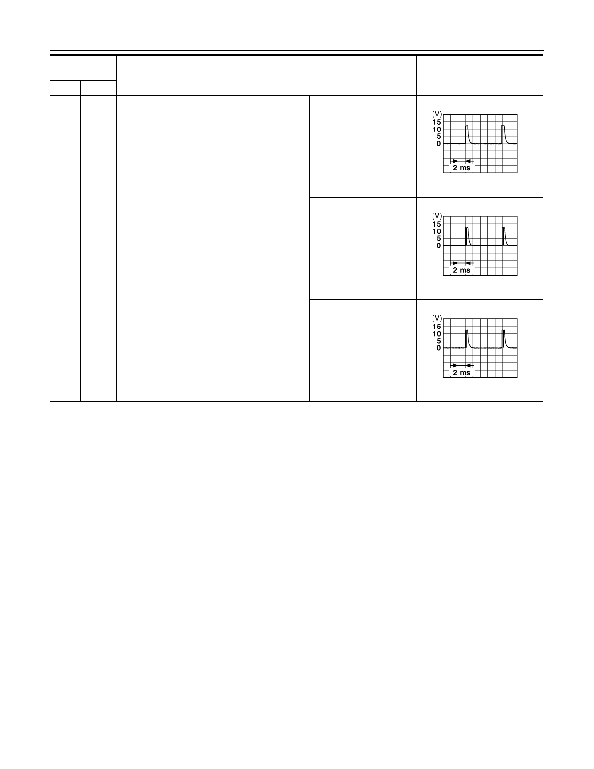
All switch OFF
(Wiper intermittent dial 4)
Front fog lamp switch ON
(Wiper intermittent dial 4)
Any of the conditions below
with all switch OFF
• Wiper intermittent dial 1
• Wiper intermittent dial 2
• Wiper intermittent dial 6
• Wiper intermittent dial 7
Value
(Approx.)
JPMIA0041G
1.4 V
JPMIA0037G
1.3 V
JPMIA0040G
1.3 V
DEF-30
Page 31
< ECU DIAGNOSIS >
B
B
B
B
B
2007 G35 Sedan
Revision: October 2006
BCM (BODY CONTROL MODULE)
Terminal No.
(Wire color)
88
Ground
(V)
Description
Signal name
Combination switch
INPUT 3
Input/
Output+–
Input
Combination
switch
Condition
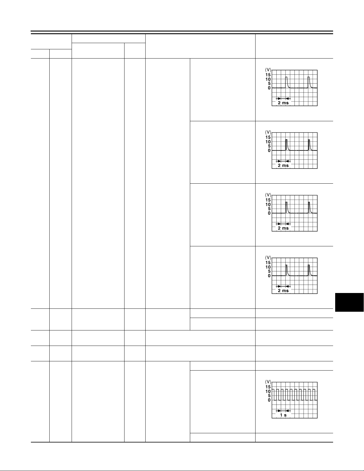
All switch OFF
(Wiper intermittent dial 4)
Lighting switch HI
(Wiper intermittent dial 4)
Lighting switch 2ND
(Wiper intermittent dial 4)
Value
(Approx.)
1.4 V
1.3 V
A
B
C
JPMIA0041G
D
E
F
JPMIA0036G
G
H
89
Ground
(BR)
90
Ground CAN - L
(P)
91
Ground CAN - H
(L)
92
Ground Key slot illumination Output
(LG)
Push-button ignition
switch (push switch)
Input
Input/
Output
Input/
Output
Push-button ignition switch (push
switch)
Key slot illumination
JPMIA0037G
1.3 V
I
J
Any of the conditions below
with all switches OFF
• Wiper inte rmi tte nt dia l 1
• Wiper inte rmi tte nt dia l 2
• Wiper inte rmi tte nt dia l 3
JPMIA0040G
1.3 V
Pressed 0 V
Not pressed Battery voltage
——
——
OFF 0 V
K
DEF
M
N
O
Blinking
P
JPMIA0015G
6.5 V
ON Battery voltage
DEF-31
Page 32
< ECU DIAGNOSIS >
B
B
2007 G35 Sedan
Revision: October 2006
BCM (BODY CONTROL MODULE)
Terminal No.
(Wire color)
93
Ground ON indicator lamp Output Ignition switch
(V)
95
Ground ACC relay control Output Ignition switch
(O)
96
(GR)
97
(L)
98
(P)
99
(R)
100
(G)
Ground
Ground
Ground
Ground
Ground
A/T device (detention
switch) power supply
Steering lock condition No. 1
Steering lock condition No. 2
Selector lever P position switch
Passenger door request switch
Description
Signal name
Input/
Output+–
Output — Battery voltage
Input Steering lock
Input Steering lock
Input Selector lever
Input
Passenger door
request switch
Condition
OFF or ACC 0 V
ON Battery voltage
OFF 0 V
ACC or ON Battery voltage
LOCK status 0 V
UNLOCK status Battery voltage
LOCK status Battery voltage
UNLOCK status 0 V
P position 0 V
Any position other than P Battery voltage
ON (Pressed) 0 V
OFF (Not pressed)
Value
(Approx.)
101
(SB)
102
(O)
103
(LG)
106
(W)
Ground
Ground
Ground
Ground
Driver door request
switch
Blower fan motor relay control
Remote keyless entry
receiver power supply
Steering wheel lock
unit power supply
ON (Pressed) 0 V
Input
Output Ignition switch
Output Ignition switch OFF Battery voltage
Output Ignition switch
Driver door request switch
OFF (Not pressed)
OFF or ACC 0 V
ON Battery voltage
OFF or ACC Battery voltage
ON 0 V
JPMIA0016G
1.0 V
JPMIA0016G
1.0 V
DEF-32
Page 33
< ECU DIAGNOSIS >
B
B
B
B
B
2007 G35 Sedan
Revision: October 2006
BCM (BODY CONTROL MODULE)
Terminal No.
(Wire color)
107
Ground
(LG)
Description
Signal name
Combination switch
INPUT 1
Input/
Output+–
Input
Combination
switch
(Wiper intermittent dial 4)
Condition
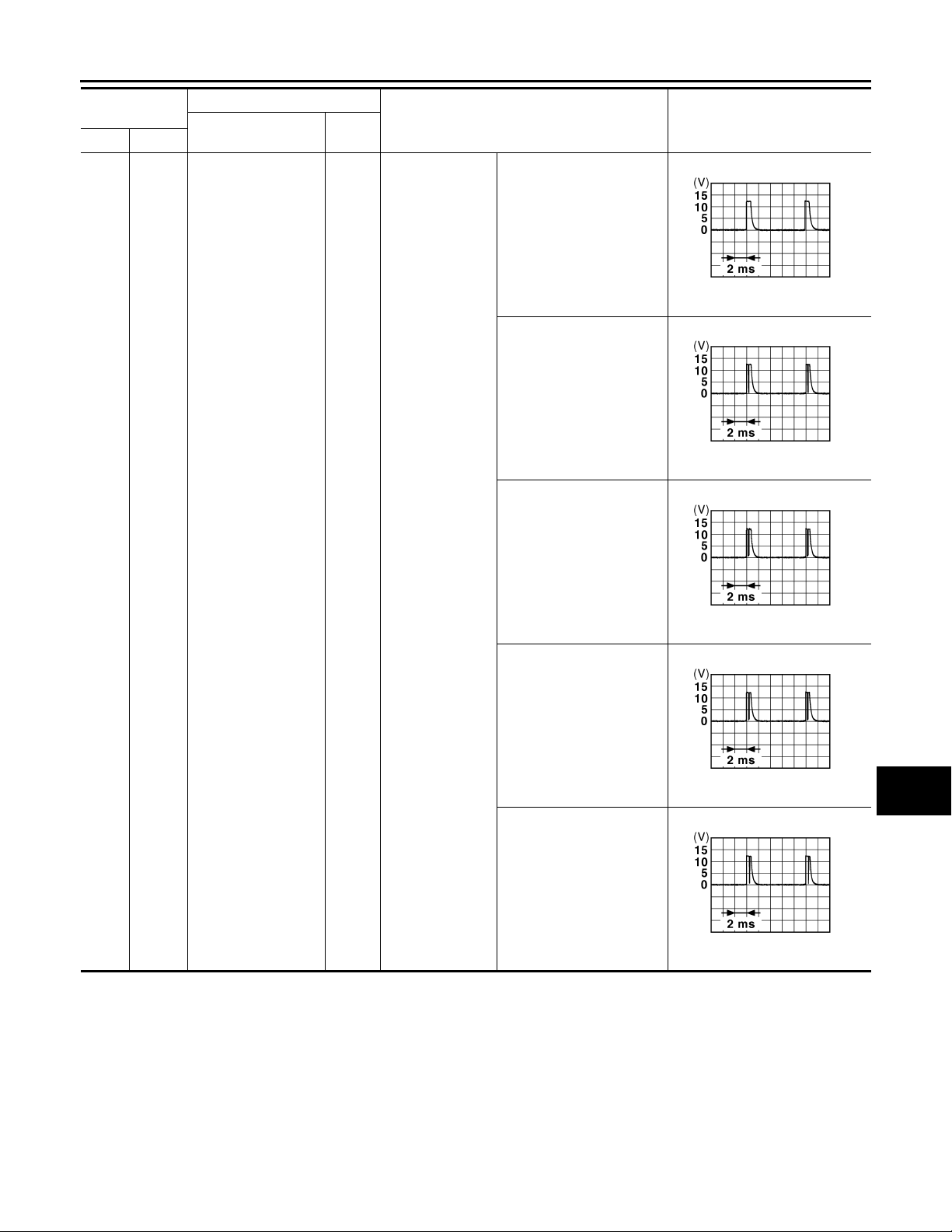
All switch OFF
Turn signal switch LH
Turn signal switch RH
Value
(Approx.)
1.4 V
1.3 V
1.3 V
JPMIA0041G
JPMIA0037G
JPMIA0036G
A
B
C
D
E
F
G
H
I
Front wiper switch LO
Front washer switch ON
1.3 V
1.3 V
J
K
JPMIA0038G
DEF
M
N
JPMIA0039G
O
P
DEF-33
Page 34
< ECU DIAGNOSIS >
B
B
B
B
2007 G35 Sedan
Revision: October 2006
BCM (BODY CONTROL MODULE)
Terminal No.
(Wire color)
108
Ground
(R)
Description
Signal name
Combination switch
INPUT 4
Input/
Output+–
Input
Combination
switch
Condition
All switch OFF
(Wiper intermittent dial 4)
Lighting switch AUTO
(Wiper intermittent dial 4)
Value
(Approx.)
JPMIA0041G
1.4 V
JPMIA0038G
1.3 V
Lighting switch 1ST
(Wiper intermittent dial 4)
Any of the conditions below
with all switches OFF
• Wiper intermittent dial 1
• Wiper intermittent dial 5
• Wiper intermittent dial 6
JPMIA0036G
1.3 V
JPMIA0039G
1.3 V
DEF-34
Page 35
< ECU DIAGNOSIS >
B
B
B
B
B
B
2007 G35 Sedan
Revision: October 2006
BCM (BODY CONTROL MODULE)
Terminal No.
(Wire color)
109
Ground
(Y)
Description
Signal name
Combination switch
INPUT 2
Input/
Output+–
Input
Combination
switch
(Wiper intermittent dial 4)
Condition
All switch OFF
Lighting switch PASS
Lighting switch 2ND
Value
(Approx.)
1.4 V
1.3 V
1.3 V
JPMIA0041G
JPMIA0037G
JPMIA0036G
A
B
C
D
E
F
G
H
I
110
Ground Hazard switch Input Hazard switch
(G)
Front wiper switch INT
Front wiper switch HI
Pressed 0 V
Not pressed
1.3 V
1.3 V
J
K
JPMIA0038G
DEF
M
N
JPMIA0040G
O
P
JPMIA0012G
1.1 V
DEF-35
Page 36
< ECU DIAGNOSIS >
B
2007 G35 Sedan
Revision: October 2006
BCM (BODY CONTROL MODULE)
Terminal No.
(Wire color)
111
Ground
(Y)
113
Ground Optical sensor signal Input
(P)
114
Ground
(R)
116
Ground Stop lamp switch 1 Input — Battery voltage
(SB)
118
Ground Stop lamp switch 2 Input
(P)
Steering lock unit
communication
Clutch interlock
switch
Description
Signal name
Input/
Output+–
Input/
Output
Input
Steering lock
Ignition switch
ON
Clutch interlock
switch
Stop lamp switch
ICC brake hold
relay (With ICC)
Condition
LOCK status Battery voltage
LOCK or UNLOCK
For 15 seconds after UNLOCK
15 seconds or later after
UNLOCK
When bright outside of the
vehicle
When dark outside of the
vehicle
OFF (Clutch pedal is not
depressed)
ON (Clutch pedal is depressed)
OFF (Brake pedal is not
depressed)
ON (Brake pedal is depressed)
OFF 0 V
ON Battery voltage
Value
(Approx.)
JMKIA0066G
Battery voltage
0 V
Close to 5 V
Close to 0 V
0 V
Battery voltage
0 V
Battery voltage
119
Ground
(SB)
121
Ground Key slot switch Input
(R)
122
Ground ACC feedback signal Input Ignition switch
(V)
123
Ground IGN feedback signal Input Ignition switch
(W)
Front door lock assembly driver side
(unlock sensor)
Input Driv er do or
When Intelligent Key is inserted into key slot Battery voltage
When Intelligent Key is not inserted into key slot 0 V
DEF-36
LOCK status
JPMIA0011GB
11.8 V
UNLOCK status 0 V
OFF 0 V
ACC or ON Battery voltage
OFF or ACC 0 V
ON Battery voltage
Page 37
< ECU DIAGNOSIS >
B
B
B
2007 G35 Sedan
Revision: October 2006
BCM (BODY CONTROL MODULE)
Terminal No.
(Wire color)
124
Ground
(LG)
129
Ground
(O)
Description
Signal name
Passenger door
switch
Trunk lid opener cancel switch
Input/
Output+–
Input
Input
Passenger door
switch
Trunk lid opener
cancel switch
Condition
OFF (When passenger
door closes)
ON (When passenger door
opens)
CANCEL
ON 0 V
0 V
Value
(Approx.)
11.8 V
1.1 V
JPMIA0011GB
JPMIA0012G
A
B
C
D
E
F
G
H
132
Ground
(V)
133
Ground
(W)
134
Ground LOCK indicator lamp Output
(GR)
137
Ground
(O)
138
Ground
(V)
Power window switch
communication
Push-button ignition
switch illumination
Receiver and sensor
ground
Receiver and sensor
power supply output
Input/
Output
Output
Input Ignition switch ON 0 V
Output Ignition switch
Ignition switch ON
Ignition switch OFF or ACC 0 V
ON (When tail lamps OFF) 5.5 V
Push-button ignition switch illumination
LOCK indicator
lamp
ON (When tail lamps ON)
OFF 0 V
ON 0 V
OFF Battery voltage
OFF 0 V
ACC or ON 5.0 V
JPMIA0013G
10.2 V
NOTE:
The pulse width of this wa ve is
varied by the illumination brightening/dimming level.
JPMIA0159G
I
J
K
DEF
M
N
O
P
DEF-37
Page 38
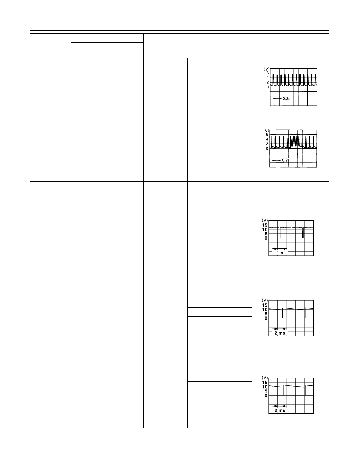
< ECU DIAGNOSIS >
B
B
B
2007 G35 Sedan
Revision: October 2006
BCM (BODY CONTROL MODULE)
Terminal No.
(Wire color)
139
Ground
(L)
140
Ground
(GR)
Description
Signal name
Tire pressure receiver signal
Selector lever P/N
position signal
Input/
Output+–
Input/
Output
Ignition switch
ON
Input Selector lever
Condition
Standby state
When receiving the signal
from the transmitter
P or N position 12.0 V
Except P and N positions 0 V
ON 0 V
Value
(Approx.)
OCC3881D
OCC3880D
141
(G)
142
(O)
143
(P)
Ground
Ground
Ground
Security indicator signal
Combination switch
OUTPUT 5
Combination switch
OUTPUT 1
Output Security indicator
Combination
Output
switch
(Wiper intermittent dial 4)
Output
Combination
switch
Blinking
OFF Battery voltage
All switch OFF 0 V
Lighting switch 1ST
Lighting switch HI
Lighting switch 2ND
Turn signal switch RH
10.7 V
All switch OFF
(Wiper intermittent dial 4)
0 V
Front wiper switch HI
(Wiper intermittent dial 4)
Any of the conditions below
with all switch OFF
• Wiper intermittent dial 1
• Wiper intermittent dial 2
• Wiper intermittent dial 3
• Wiper intermittent dial 6
• Wiper intermittent dial 7
10.7 V
JPMIA0014G
11.3 V
JPMIA0031G
JPMIA0032G
DEF-38
Page 39
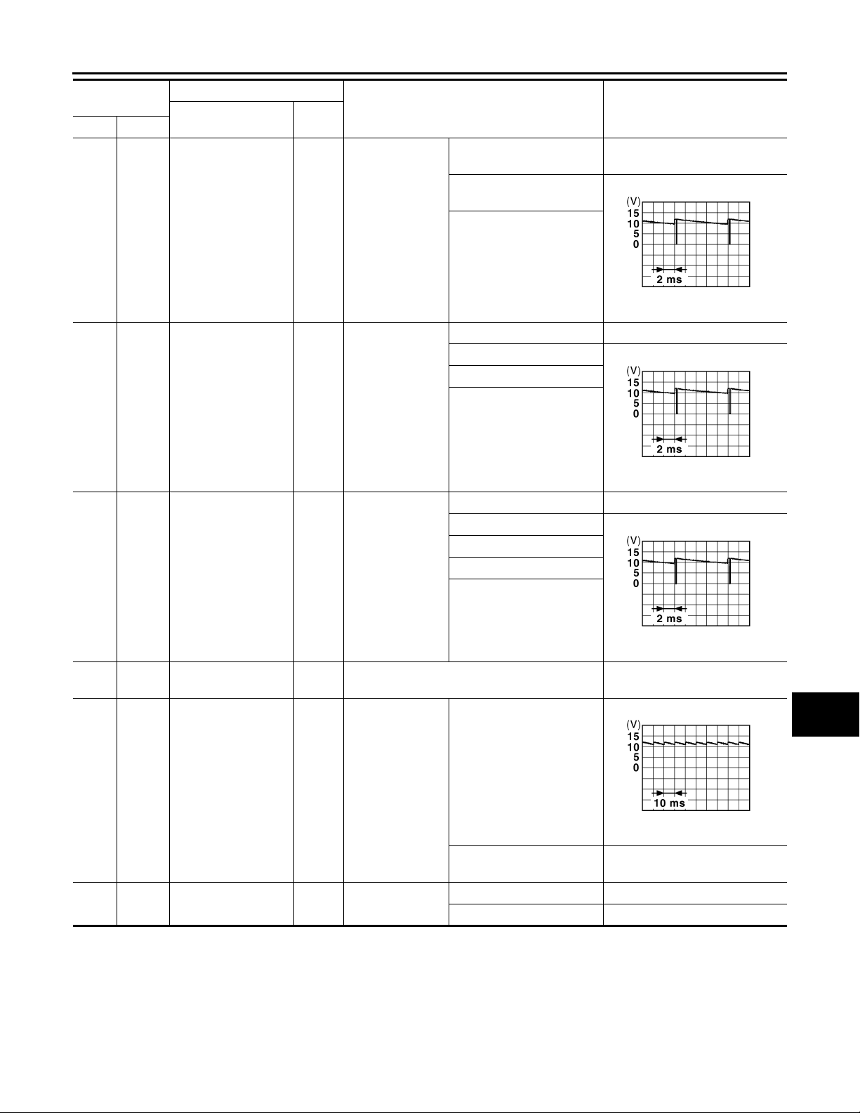
< ECU DIAGNOSIS >
B
B
B
2007 G35 Sedan
Revision: October 2006
BCM (BODY CONTROL MODULE)
Terminal No.
(Wire color)
144
Ground
(G)
145
Ground
(L)
146
Ground
(SB)
149
Ground
(W)
Description
Signal name
Combination switch
OUTPUT 2
Combination switch
OUTPUT 3
Combination switch
OUTPUT 4
Tire pressure warning check switch
Input/
Output+–
Output
Output
Output
Input — 5 V
Combination
switch
Combination
switch
(Wiper intermittent dial 4)
Combination
switch
(Wiper intermittent dial 4)
Condition
All switch OFF
(Wiper intermittent dial 4)
Front washer switch ON
(Wiper intermittent dial 4)
Any of the conditions below
with all switches OFF
• Wiper inte rmi tte nt dia l 1
• Wiper inte rmi tte nt dia l 5
• Wiper inte rmi tte nt dia l 6
All switches OFF 0 V
Front wiper switch INT
Front wiper switch LO
Lighting switch AUTO
All switch OFF 0 V
Front fog lamp switch ON
Lighting switch 2ND
Lighting switch PASS
Turn signal switch LH
0 V
Value
(Approx.)
10.7 V
10.7 V
10.7 V
A
B
C
D
JPMIA0033G
E
F
G
JPMIA0034G
H
I
J
JPMIA0035G
K
150
Ground Driver door switch Inpu t
(GR)
151
Ground
(G)
Rear window defogger relay
Output
Driver door
switch
Rear window defogger
DEF-39
OFF (When driver door
closes)
ON (When driver door
opens)
Active 0 V
Not activated Battery voltage
0 V
11.8 V
JPMIA0011GB
DEF
M
N
O
P
Page 40
< ECU DIAGNOSIS >
B
2007 G35 Sedan
Revision: October 2006
BCM (BODY CONTROL MODULE)
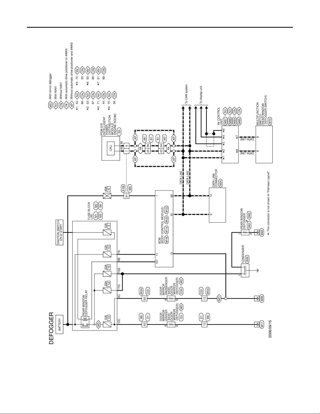
Wiring Diagram —DEFOGGER—
INFOID:0000000000962705
JCLWA0069G
DEF-40
Page 41
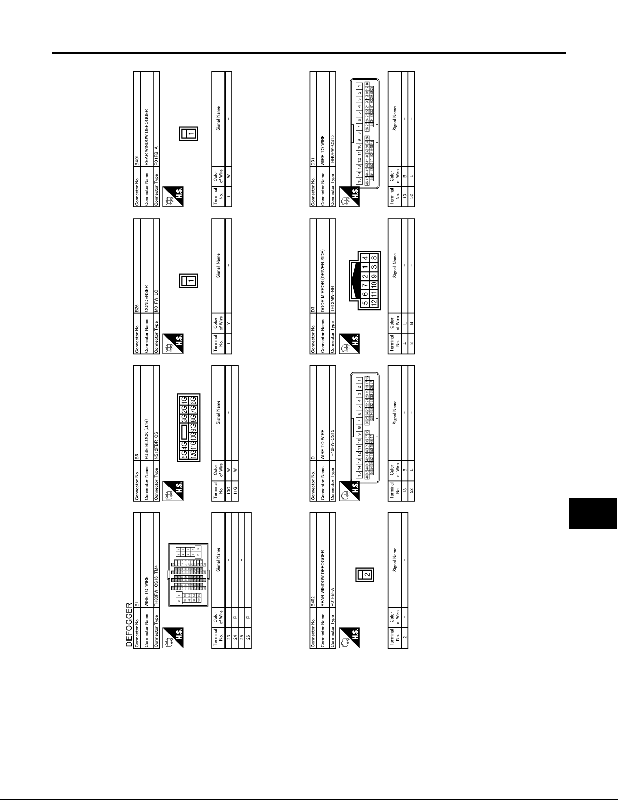
< ECU DIAGNOSIS >
B
2007 G35 Sedan
Revision: October 2006
BCM (BODY CONTROL MODULE)
A
B
C
D
E
F
G
H
I
J
K
DEF
M
N
O
JCLWA0070G
P
DEF-41
Page 42
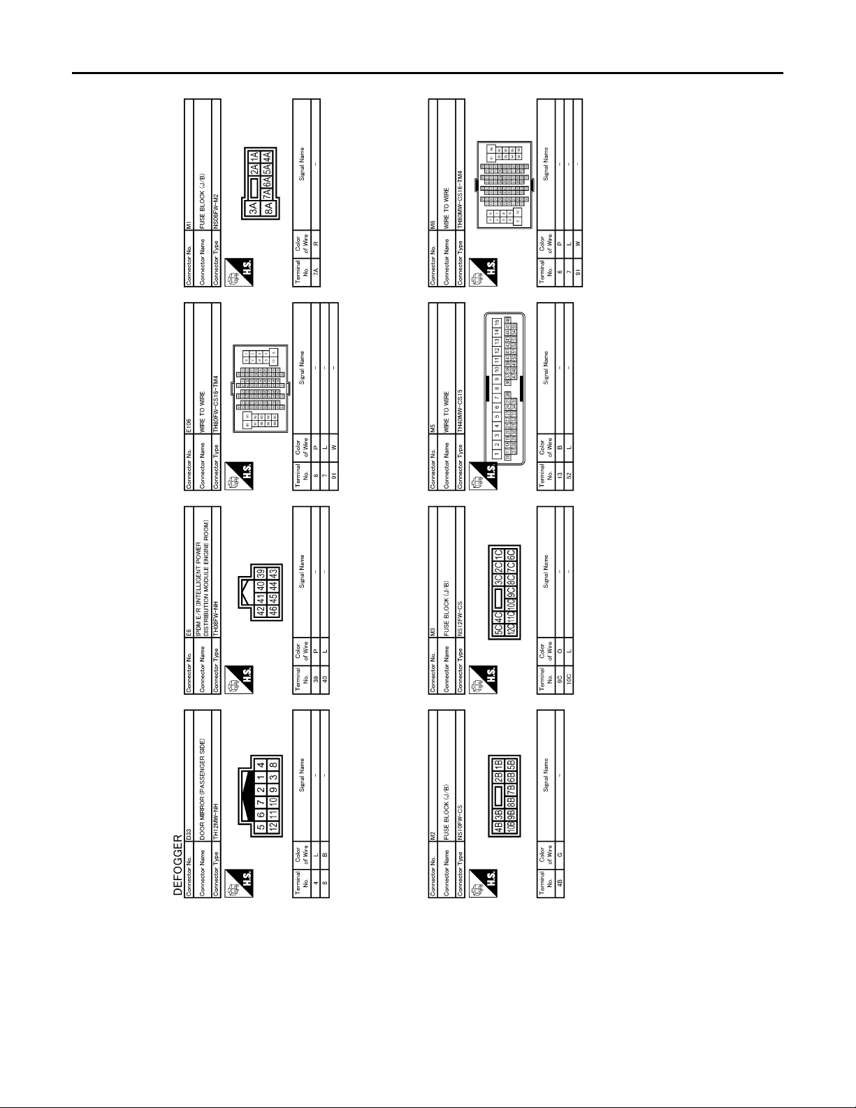
< ECU DIAGNOSIS >
B
2007 G35 Sedan
Revision: October 2006
BCM (BODY CONTROL MODULE)
JCLWA0071G
DEF-42
Page 43
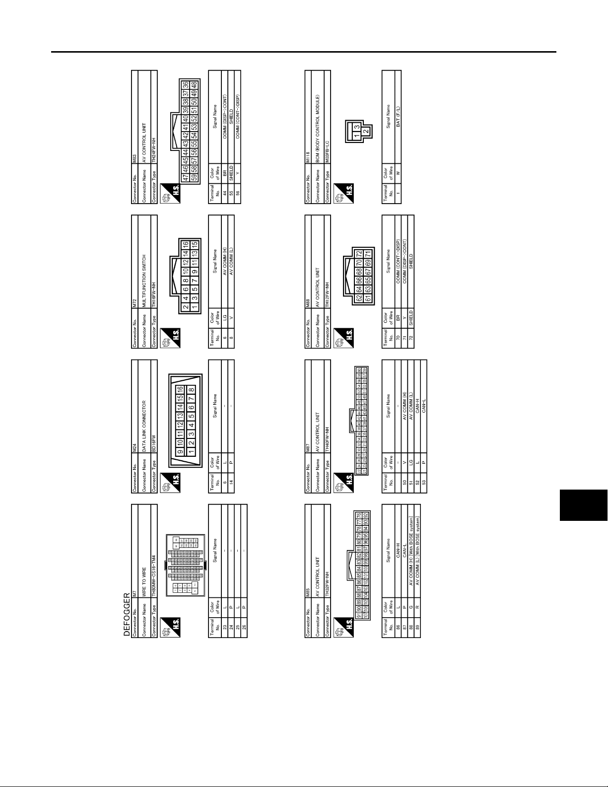
< ECU DIAGNOSIS >
B
2007 G35 Sedan
Revision: October 2006
BCM (BODY CONTROL MODULE)
A
B
C
D
E
F
G
H
I
J
K
DEF
M
N
O
JCLWA0072G
P
DEF-43
Page 44
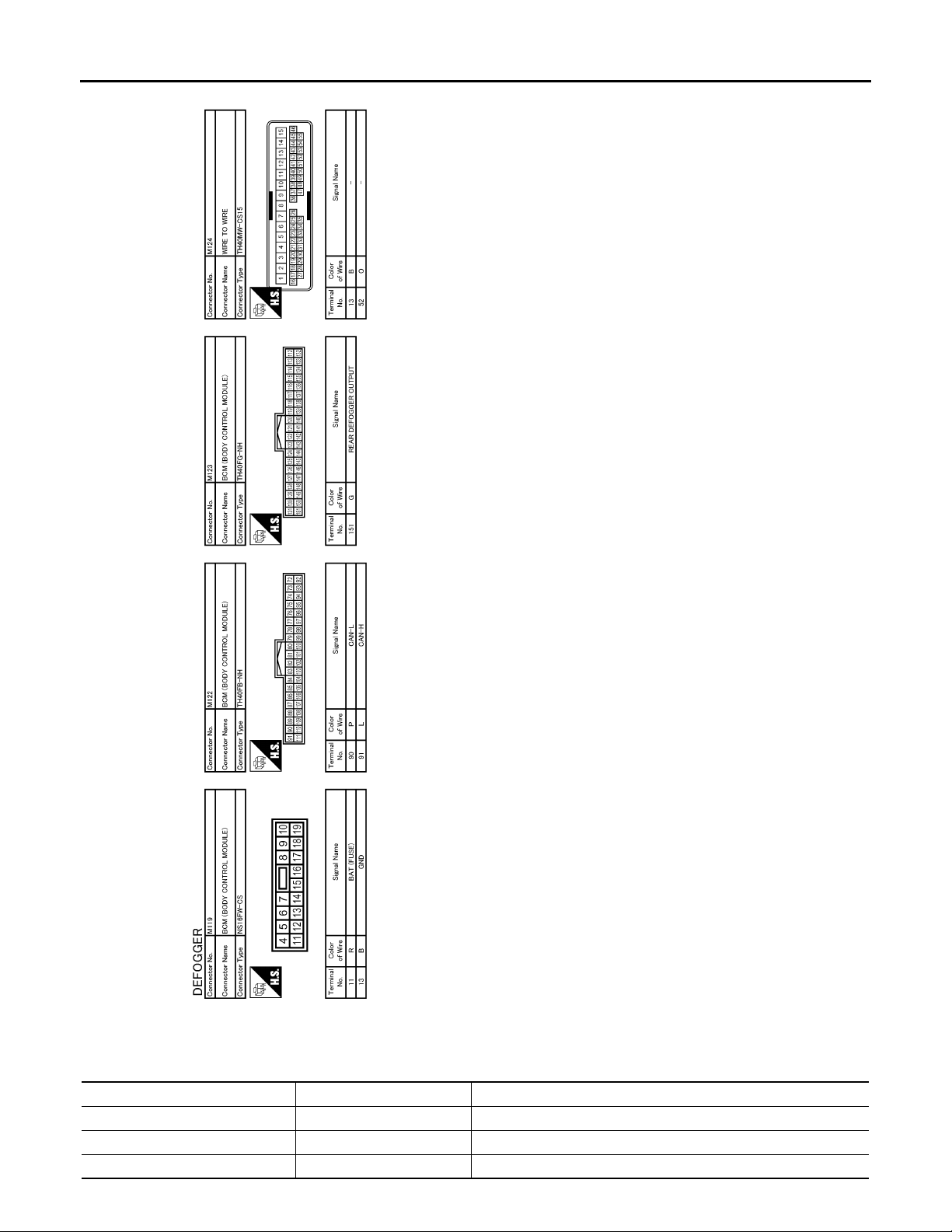
< ECU DIAGNOSIS >
B
2007 G35 Sedan
Revision: October 2006
BCM (BODY CONTROL MODULE)
Fail Safe
Display contents of CONSULT Fail-safe Cancellation
B2013: ID DISCORD BCM-S/L Inhibit engine cranking Erase DTC
B2014: CHAIN OF S/L-BCM Inhibit engine cranking Erase DTC
B2190: NATS ANTTENA AMP Inhibit engine cranking Erase DTC
JCLWA0073G
INFOID:0000000000962706
DEF-44
Page 45

< ECU DIAGNOSIS >
2007 G35 Sedan
Revision: October 2006
BCM (BODY CONTROL MODULE)
Display contents of CONSULT Fail-safe Cancellation
B2191: DIFFERENCE OF KEY Inhib it en gin e cra nking Erase DTC
B2192: ID DISCORD BCM-ECM Inhib it en gin e crank ing Erase DTC
B2193: CHAIN OF BCM-ECM Inhibit engine cranking Erase DTC
B2557: VEHICLE SPEED Inhibit steering lock
B2560: STARTER CONT RELAY Inhibit engine cranking
B2563: HI VOLTAGE
B2601: SHIFT POSITION Inhibit steering lock
B2602: SHIFT POSITION Inhibit steering lock
B2603: SHIFT POSI STATUS Inhibit steering lock
B2604: PNP SW Inhibit steering lock
B2605: PNP SW Inhibit steering lock
B2606: S/L RELAY Inhibit engine cranking
B2607: S/L RELAY Inhibit engine cranking
• Inhibit engine cranking
• Inhibit steering lock
When normal vehicle speed signals have been received from ABS
actuator and electric unit (control unit) for 500 ms
500 ms after the followin g CAN signal communication status has
become consistent
• Starter control relay signal
• Starter relay status signal
500 ms after the power supply voltage decreases to less than 18 V
500 ms after the foll owin g si gnal re cept ion status becomes consis-
tent
• Selector lever P position switch signal
• P range signal (CAN)
5 seconds after the following BCM recognition conditions are ful-
filled
• Ignition switch is in the ON position
• Selector lever P position switch signal: Except P position (battery
voltage)
• Vehicle speed: 4 /h or more
500 ms after the following BCM recognition conditions are fulfilled
• Ignition switch is in the ON position
• Selector lever P position switch signal: Except P position (battery
voltage)
• Selector lever P/N position signal: Except P and N positions (0 V)
500 ms after any of the followin g BCM recognit ion conditi ons is fulfilled
•Status 1
- Ignition switch is in the ON position
- Selector lever P/N position signal: P and N position (battery voltage)
- P range signal or N range signal (CAN): ON
•Status 2
- Ignition switch is in the ON position
- Selector lever P/N position signal: Except P and N positions (0 V)
- P range signal and N range signal (CAN): OFF
500 ms after any of the followin g BCM recognit ion conditi ons is fulfilled
• Ignition switch is in the ON position
- Power position: IGN
- Selector lever P/N position signal: Except P and N positions (0 V)
- Interlock/PNP switch signal (CAN): OFF
•Status 2
- Ignition switch is in the ON position
- Selector lever P/N position signal: P or N position (battery voltage)
- PNP switch signal (CAN): ON
500 ms after the followin g CAN signal communication status has
become consistent
• Steering lock relay signal (Request sig na l)
• Steering lock relay signal (Condition signal)
500 ms after the followin g CAN signal communication status has
become consistent
• Steering lock relay signal (Request sig na l)
• Steering lock relay signal (Condition signal)
A
B
C
D
E
F
G
H
I
J
K
DEF
M
N
O
P
DEF-45
Page 46

BCM (BODY CONTROL MODULE)
2007 G35 Sedan
Revision: October 2006
< ECU DIAGNOSIS >
Display contents of CONSULT Fail-safe Cancellation
500 ms after the following signal communication status becomes
B2608: STARTER RELAY Inhibit engine cranking
B2609: S/L STATUS
B260A: IGNITION RELAY Inhibit engine cranking
B260F: ENG STATE SIG LOST
B2612: S/L STATUS
B2617: STARTER RELAY CIRC Inhibit engine cranking
B2618: BCM Inhibit engine cranking
B2619: BCM Inhibit engine cranking
B261E: VEHICLE TYPE Inhibit engine cranking BCM initialization
B26E1: ENG STATE NO RECIV Inhibit engine cranking
• Inhib it engine cranking
• Inhib it ste ering lock
Maintains the power supply
position attained at the time
of DTC detection
• Inhib it engine cranking
• Inhib it ste ering lock
consistent
• Starter motor relay control signal
• Starter relay status signal (CAN)
When the following steering lock conditions agree
• BCM steering lock control status
• Steering lock condition No. 1 signal status
• Steering lock condition No. 2 signal status
500 ms after the following conditions are fulfilled
• IGN relay (IPDM E/R) control signal: OFF (Battery voltage)
• Ignition ON signal (CAN to IPDM E/R): OFF (Request signal)
• Ignition ON signal (CAN from IPDM E/R): OFF (Condition signal)
When any of the following conditions is fulfilled
• Power position changes to ACC
• Receives engine status signal (CAN)
When any of the following conditions is fulfilled
• Steering lock unit status signal (CAN) is received normally
• The BCM steering lock control status matches the steering lock
status recognized by the steering lock unit status signal (CAN
from IPDM E/R)
1 second after the st arter motor relay control insi de BCM becomes
normal
1 second after the ignition relay (IPDM E/R) control inside BCM becomes normal
1 second after the steering lock unit power supply ou tput control inside BCM becomes normal
When any of the following conditions is fulfilled
• Power position changes to ACC
• Receives engine status signal (CAN)
DTC Inspection Priority Chart
INFOID:0000000000962707
If some DTCs are displayed at the same time, perform inspections one by one based on the following priority
chart.
Priority DTC
1
2
3
• B2562: LOW VOLTAGE
• B2563: HI VOLTAGE
• U1000: CAN COMM CIRCUIT
• U1010: CONTROL UNIT (CAN)
• B2190: NATS ANTTENA AMP
• B2191: DIFFERENCE OF KEY
• B2192: ID DISCORD BCM-ECM
• B2193: CHAIN OF BCM-ECM
DEF-46
Page 47

< ECU DIAGNOSIS >
2007 G35 Sedan
Revision: October 2006
BCM (BODY CONTROL MODULE)
Priority DTC
• B2013: ID DISCORD BCM-S/L
• B2014: CHAIN OF S/L-BCM
• B2553: IGNITION RELAY
• B2555: STOP LAMP
• B2556: PUSH-BTN IGN SW
• B2557: VEHICLE SPEED
• B2560: STARTER CONT RELAY
• B2601: SHIFT POSITION
• B2602: SHIFT POSITION
• B2603: SHIFT POSI STATUS
• B2604: PNP SW
• B2605: PNP SW
• B2606: S/L RELAY
• B2607: S/L RELAY
• B2608: STARTER RELAY
• B2609: S/L STATUS
4
5
6
• B260A: IGNITION RELAY
• B260B: STEERING LOCK UNIT
• B260C: STEERI NG LOCK UNIT
• B260D: STEERI NG LOCK UNIT
• B260F: ENG STATE SIG LOST
• B2611: ACC RELAY
• B2612: S/L STATUS
• B2614: ACC RELAY CIRC
• B2615: BLOWER RELAY CIRC
• B2616: IGN RELAY CIRC
• B2617: STARTER RELAY CIRC
• B2618: BCM
• B2619: BCM
• B261A: PUSH-BTN IGN SW
• B261E: VEHICLE TYPE
• B26E1: ENG STATE NO RECIV
• C1729: VHCL SPEED SIG ERR
• U0415: VEHICLE SPEED SIG
• C1704: LOW PRESSURE FL
• C1705: LOW PRESSURE FR
• C1706: LOW PRESSURE RR
• C1707: LOW PRESSURE RL
• C1708: [NO DATA] FL
• C1709: [NO DATA] FR
• C1710: [NO DATA] RR
• C1711: [NO DATA] RL
• C1712: [CHECKSUM ERR] FL
• C1713: [CHECKSUM ERR] FR
• C1714: [CHECKSUM ERR] RR
• C1715: [CHECKSUM ERR] RL
• C1716: [PRESSDATA ERR] FL
• C1717: [PRESSDATA ERR] FR
• C1718: [PRESSDATA ERR] RR
• C1719: [PRESSDATA ERR] RL
• C1720: [CODE ERR] FL
• C1721: [CODE ERR] FR
• C1722: [CODE ERR] RR
• C1723: [CODE ERR] RL
• C1724: [BATT VOLT LOW] FL
• C1725: [BATT VOLT LOW] FR
• C1726: [BATT VOLT LOW] RR
• C1727: [BATT VOLT LOW] RL
• C1734: CONTROL UNIT
• B2621: INSIDE ANTENNA
• B2622: INSIDE ANTENNA
• B2623: INSIDE ANTENNA
A
B
C
D
E
F
G
H
I
J
K
DEF
M
N
O
P
DTC Index INFOID:0000000000962708
DEF-47
Page 48

BCM (BODY CONTROL MODULE)
2007 G35 Sedan
Revision: October 2006
< ECU DIAGNOSIS >
NOTE:
Details of time display
• CRNT: Displays when there is a malfunction now or after returning to the normal condition until turning ignition switch OFF → ON again.
• 1 - 39: Displayed if any previous malfunction is present when current condition is normal. It increases like 1
→ 2 → 3...38 → 39 after returning to the normal condition whenever ignition switch OFF → ON. The counter
remains at 39 even if the number of cycles exceeds it. It is counted from 1 again when turning ignition switch
OFF → ON after returning to the normal condition if the malfunction is detected again.
CONSULT display Fail-safe
No DTC is detected.
further testing
may be required.
U1000: CAN COMM CIRCUIT — — — BCS-33
U1010: CONTROL UNIT (CAN) — — — BCS-34
U0415: VEHICLE SPEED SIG — — — BCS-35
B2013: ID DISCORD BCM-S/L × ——SEC-43
B2014: CHAIN OF S/L-BCM × ——SEC-44
B2190: NATS ANTTENA AMP × ——SEC-37
B2191: DIFFERENCE OF KEY × ——SEC-40
B2192: ID DISCORD BCM-ECM × ——SEC-41
B2193: CHAIN OF BCM-ECM × ——SEC-42
B2553: IGNITION RELAY — — — PCS-48
B2555: STOP LAMP — — — SEC-47
B2556: PUSH-BTN IGN SW — × — SEC-49
B2557: VEHICLE SPEED ××— SEC-51
B2560: STARTER CONT RELAY ××— SEC-52
B2562: LOW VOLTAGE — — — BCS-36
B2563: HI VOLTAGE ××— BCS-37
B2601: SHIFT POSITION ××— SEC-53
B2602: SHIFT POSITION ××— SEC-56
B2603: SHIFT POSI STATUS ××— SEC-58
B2604: PNP SW ××— SEC-61
B2605: PNP SW ××— SEC-63
B2606: S/L RELAY ××— SEC-65
B2607: S/L RELAY ××— SEC-66
B2608: STARTER RELAY ××— SEC-68
B2609: S/L STATUS ××— SEC-70
B260A: IGNITION RELAY ××— PCS-50
B260B: STEERING LOCK VNIT — × — SEC-74
B260C: STEERING LOCK VNIT — × — SEC-75
B260D: STEERING LOCK VNIT — × — SEC-76
B260F: ENG STATE SIG LOST ××— SEC-77
B2611: ACC RELAY — — — PCS-52
B2612: S/L STATUS ××— SEC-79
B2614: ACC RELAY CIRC — × — PCS-54
B2615: BLOWER RELAY CIRC — × — PCS-57
————
Intelligent Key
warning lamp ON
Tire pressure
monitor warning
lamp ON
Reference page
DEF-48
Page 49

< ECU DIAGNOSIS >
2007 G35 Sedan
Revision: October 2006
BCM (BODY CONTROL MODULE)
CONSULT display Fail-safe
B2616: IGN RELAY CIRC — × — PCS-60
B2617: STARTER RELAY CIRC ××— SEC-83
B2618: BCM ××— PCS-63
B2619: BCM ××— SEC-85
B261A: PUSH-BTN IGN SW — × — SEC-86
B261E: VEHICLE TYPE ×
B2621: INSIDE ANTENNA — — — DLK-58
B2622: INSIDE ANTENNA — — — DLK-60
B2623: INSIDE ANTENNA — — — DLK-62
B26E1: ENG STATE NO RES ××— SEC-78
C1704: LOW PRESSURE FL — — × WT-14
C1705: LOW PRESSURE FR — — × WT-14
C1706: LOW PRESSURE RR — — × WT-14
C1707: LOW PRESSURE RL — — × WT-14
C1708: [NO DATA] FL — — × WT-16
C1709: [NO DATA] FR — — × WT-16
C1710: [NO DATA] RR — — × WT-16
C1711: [NO DATA] RL — — × WT-16
C1712: [CHECKSUM ERR] FL — — × WT-19
C1713: [CHECKSUM ERR] FR — — × WT-19
C1714: [CHECKSUM ERR] RR — — × WT-19
C1715: [CHECKSUM ERR] RL — — × WT-19
C1716: [PRESSDATA ERR] FL — — × WT-22
C1717: [PRESSDATA ERR] FR — — × WT-22
C1718: [PRESSDATA ERR] RR — — × WT-22
C1719: [PRESSDATA ERR] RL — — × WT-22
C1720: [CODE ERR] FL — — × WT-24
C1721: [CODE ERR] FR — — × WT-24
C1722: [CODE ERR] RR — — × WT-24
C1723: [CODE ERR] RL — — × WT-24
C1724: [BATT VOLT LOW] FL — — × WT-27
C1725: [BATT VOLT LOW] FR — — × WT-27
C1726: [BATT VOLT LOW] RR — — × WT-27
C1727: [BATT VOLT LOW] RL — — × WT-27
C1729: VHCL SPEED SIG ERR — — × WT-30
C1734: CONTROL UNIT — — × WT-31
Intelligent Key
warning lamp ON
× (Turn ON for 15
seconds)
Tire pressure
monitor warning
lamp ON
— SEC-88
Reference page
A
B
C
D
E
F
G
H
I
J
K
DEF
M
N
O
P
DEF-49
Page 50

REAR WINDOW DEFOGGER AND DOOR MIRROR DEFOGGER DO NOT OPER-
2007 G35 Sedan
Revision: October 2006
ATE.
< SYMPTOM DIAGNOSIS >
SYMPTOM DIAGNOSIS
REAR WINDOW DEFOGGER AND DOOR MIRROR DEFOGGER DO NOT OPERATE.
Diagnosis Procedure INFOID:0000000000962709
1.CHECK REAR WINDOW DEFOGGER SWITCH
Check rear window defogger switch.
Refer to DEF-11, "
Is the inspection result normal?
YES >> GO TO 2.
NO >> Repair or replace the malfunctioning parts.
2.CHECK REAR WINDOW DEFOGGER RELAY
Check rear window defogger relay.
Refer to DEF-9, "
Is the inspection result normal?
YES >> Refer to GI-39, "Intermittent Incident".
NO >> Repair or replace the malfunctioning parts.
Component Function Check".
Component Function Check".
DEF-50
Page 51

REAR WINDOW DEFOGGER DOES NOT OPERATE BUT BOTH OF DOOR MIR-
2007 G35 Sedan
Revision: October 2006
ROR DEFOGGER OPERATE.
< SYMPTOM DIAGNOSIS >
REAR WINDOW DEFOGGER DOES NOT OPERA TE BUT BOTH OF DOOR MIRROR DEFOGGER OPERATE.
Diagnosis Procedure INFOID:0000000000962710
1.CHECK REAR WINDOW DEFOGGER POWER SUPPLY AND GROUND CIRCUIT
Check rear window defogger power supply and ground circuit.
Refer to DEF-11, "
Is the inspection result normal?
YES >> Refer to GI-39, "Intermittent Incident".
NO >> Repair or replace the malfunctioning parts.
Component Function Check".
A
B
C
D
E
F
G
H
I
J
K
DEF
M
N
O
P
DEF-51
Page 52

BOTH DOORS MIRROR DEFOGGER DON’T OPERATE BUT REAR WINDOW
2007 G35 Sedan
Revision: October 2006
DEFOGGER OPERATES
< SYMPTOM DIAGNOSIS >
BOTH DOORS MIRROR DEFOGGER DON’T OPERATE BUT REAR WINDOW DEFOGGER OPERATES
Diagnosis Procedure INFOID:0000000000962711
1.CHECK INTERMITTENT INCIDENT
Check intermittent incident.
Refer to GI-39, "
Is the inspection result normal?
YES >> Check the following.
NO >> Repair or replace the malfunctioning parts.
Intermittent Incident".
• Batter power supply circuit.
• Fuse block (J/B).
DEF-52
Page 53

DRIVER SIDE DOOR MIRROR DEFOGGER DOES NOT OPERATE.
2007 G35 Sedan
Revision: October 2006
< SYMPTOM DIAGNOSIS >
DRIVER SIDE DOOR MIRROR DEFOGGER DOES NOT OPERATE.
Diagnosis Procedure INFOID:0000000000962712
1.CHECK DRIVER SIDE DOOR MIRROR DEFOGGER
Check driver side door mirror defogger.
Refer to DEF-13, "
Is the inspection result normal?
YES >> Refer to GI-39, "Intermittent Incident".
NO >> Repair or replace the malfunctioning parts.
Component Function Check".
A
B
C
D
E
F
G
H
I
J
K
DEF
M
N
O
P
DEF-53
Page 54

PASSENGER SIDE DOOR MIRROR DEFOGGER DOES NOT OPERATE.
2007 G35 Sedan
Revision: October 2006
< SYMPTOM DIAGNOSIS >
PASSENGER SIDE DOOR MIRROR DEFOGGER DOES NOT OPERATE.
Diagnosis Procedure INFOID:0000000000962713
1.CHECK PASSENGER SIDE DOOR MIRROR DEFOGGER
Check passenger side door mirror defogger.
Refer to DEF-15, "
Is the inspection result normal?
YES >> Refer to GI-39, "Intermittent Incident".
NO >> Repair or replace the malfunctioning parts.
Component Function Check".
DEF-54
Page 55

ON ISN’T DISPLAYED WHEN PRESSING REAR WINDOW DEFOGGER SWITCH
2007 G35 Sedan
Revision: October 2006
BUT IT IS OPERATED
< SYMPTOM DIAGNOSIS >
ON ISN’T DISPLAYED WHEN PRESSING REAR WINDOW DEFOGGER SWITCH BUT IT IS OPERATED
Diagnosis Procedure INFOID:0000000000962714
CHECK AV CONTROL UNIT FUNCTION
1.
Check that the A V control unit is operating normally.
Base audio without navigation refer to AV-10, "
Bose audio without navigation refer to AV-125, "
Bose audio with navigation refer to AV-313, "
Is the inspection result normal?
YES >> Refer to GI-39, "Intermittent Incident".
NO >> Repair or replace the malfunctioning parts.
Work Fl ow".
Work Fl ow".
Work Flow".
A
B
C
D
E
F
G
H
I
J
K
DEF
M
N
O
P
DEF-55
Page 56

REAR WINDOW DEFOGGER SWITCH DOES NOT LIGHT, BUT REAR WINDOW
2007 G35 Sedan
Revision: October 2006
DEFOGGER OPERATES
< SYMPTOM DIAGNOSIS >
REAR WINDOW DEFOGGER SWITCH DOES NOT LIGHT , BUT REAR WINDOW DEFOGGER OPERATES
Diagnosis Procedure INFOID:0000000000962715
1.REPLACE MULTIFUNCTION SWITCH (REAR WINDOW DEFOGGER SWITCH)
Replace multifunction switch (rear window defogger switch) .
>> Refer to AV-541, "
Removal and Installation".
DEF-56
Page 57

< PRECAUTION >
2007 G35 Sedan
Revision: October 2006
PRECAUTIONS
PRECAUTION
PRECAUTIONS
Precaution for Supplemental Restraint System (SRS) "AIR BAG" and "SEAT BELT PRE-TENSIONER" INFOID:0000000000962716
The Supplemental Restraint System such as “AIR BAG” and “SEAT BELT PRE-TENSIONER”, used along
with a front seat belt, helps to reduce the risk or severity of injury to the driver and front passenger for certain
types of collision. This system includes seat belt switch inputs and dual stage front air bag modules. The SRS
system uses the seat belt switches to determine the front air bag deployment, and may only deploy one front
air bag, depending on the severity of a collision and whether the front occupants are belted or unbelted.
Information necessary to service the system safely is included in the SRS and SB section of this Service Manual.
WARNING:
• To avoid rendering the SRS inoperative, which could increase the risk of personal injury or death in
the event of a collision which would result in air bag inflation, all maintenance must be performed by
an authorized NISSAN/INFINITI dealer.
• Improper maintenance, including incorrect removal and installation of the SRS, can lead to personal
injury caused by unintentional activation of the system. For removal of Spiral Cable and Air Bag
Module, see the SRS section.
• Do not use electrical test equipm ent on any circuit related to the SRS unless instructed to in this
Service Manual. SRS wiring harnesses can be identified by yellow and/or orange harnesses or harness connectors.
A
B
C
D
E
F
G
H
I
J
K
DEF
M
N
O
P
DEF-57
Page 58

PRE-INSPECTION FOR DIAGNOSTIC
2007 G35 Sedan
Revision: October 2006
< ON-VEHICLE MAINTENANCE >
ON-VEHICLE MAINTENANCE
PRE-INSPECTION FOR DIAGNOSTIC
Basic Inspection INFOID:0000000000962717
BASIC INSPECTION
1.INSPECTION START
1. Check the service history.
2. Check the following parts.
• Fuse/circuit breaker blown.
• Poor connection, open or short circuit of harness connector.
• Battery voltage.
Is the inspection result normal?
YES >> Inspection end.
NO >> Repair or replace the malfunctioning parts.
DEF-58
Page 59
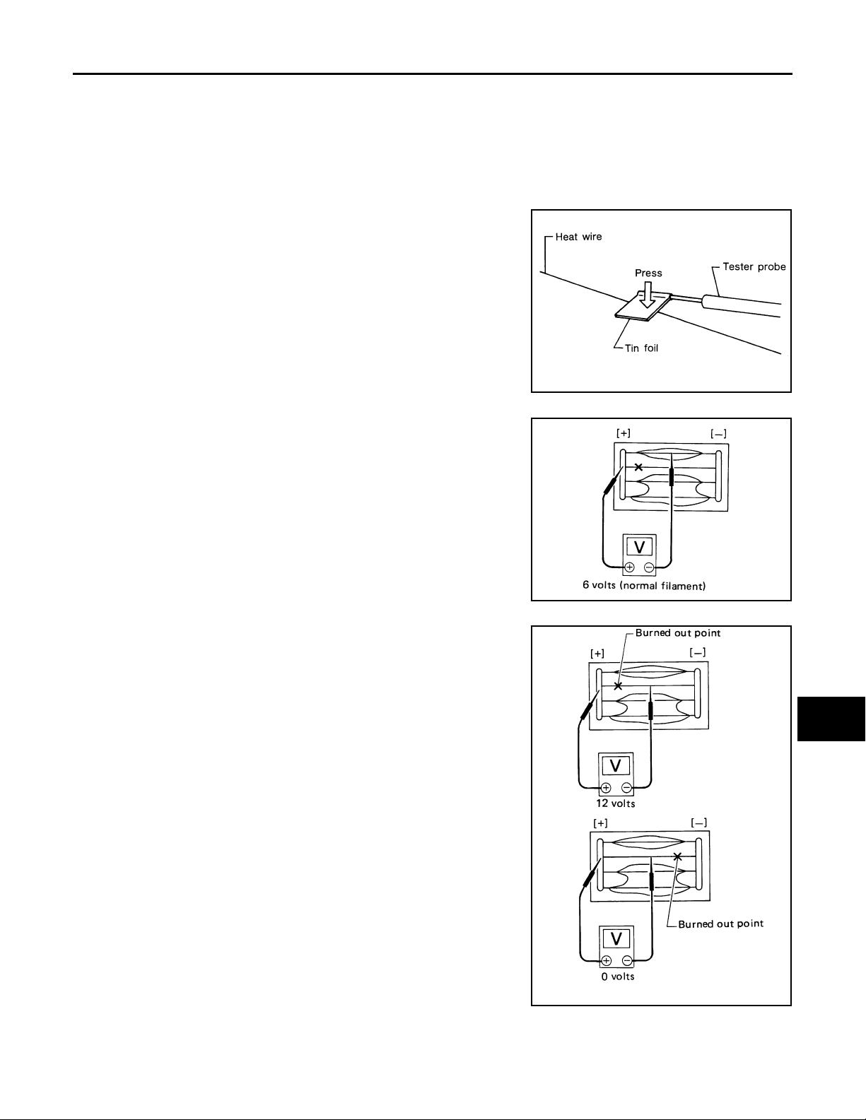
< ON-VEHICLE REPAIR >
2007 G35 Sedan
Revision: October 2006
FILAMENT
ON-VEHICLE REPAIR
FILAMENT
Inspection and Repair INFOID:0000000000962718
INSPECTION
1. When measuring voltage, wrap tin foil around the top of the neg-
ative probe. Then press the foil against the wire with your finger.
SEL122R
2. Attach probe circuit tester (in Volt range) to middle portion of
each filament.
A
B
C
D
E
F
G
H
3. If a filament is burned out, circuit tester registers 0 or battery
voltage.
4. To locate burned out point, move probe to left and right along fil-
ament. Test needle will swing abruptly when probe passes the
point.
I
SEL263
J
K
DEF
M
N
O
P
REPAIR
REPAIR EQUIPMENT
• Conductive silver composition (Dupont No. 4817 or equivalent)
SEL265
DEF-59
Page 60
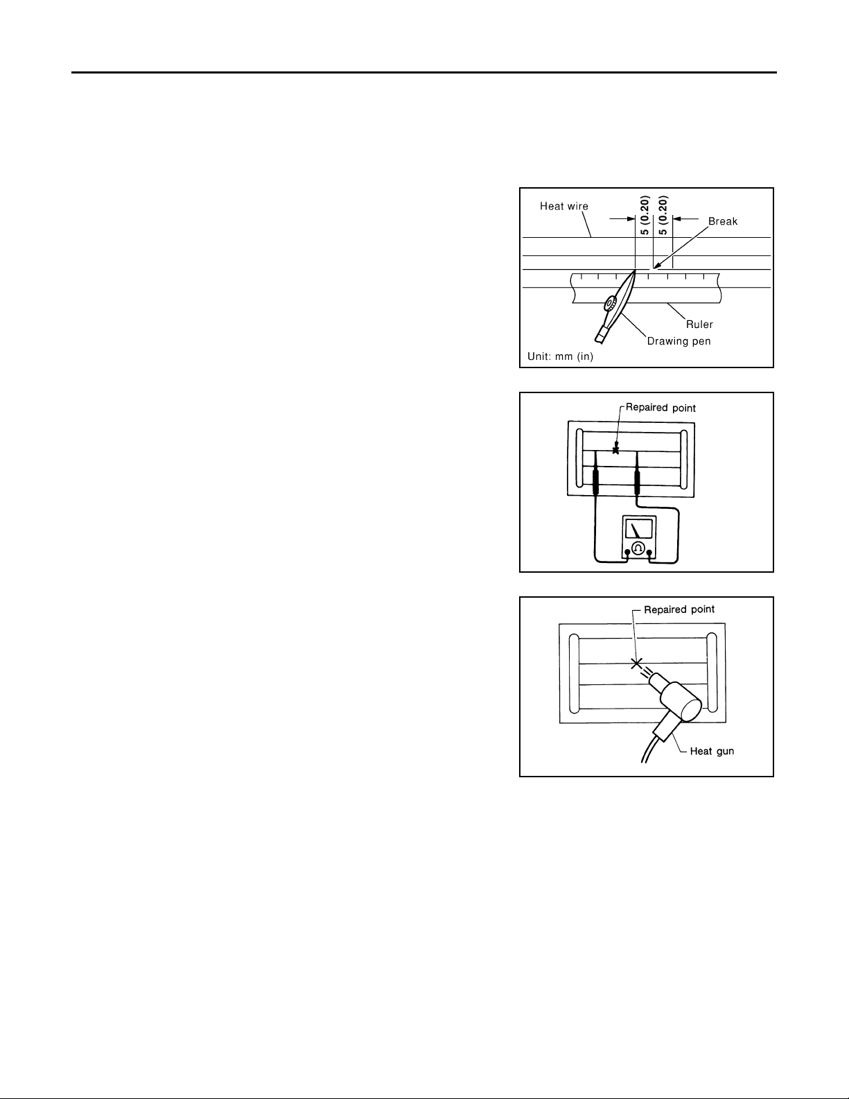
FILAMENT
2007 G35 Sedan
Revision: October 2006
< ON-VEHICLE REPAIR >
• Ruler 30 cm (11.8 in) long
• Drawing pen
• Heat gun
• Alcohol
• Cloth
REPAIRING PROCEDURE
1. Wipe broken heat wire and its surrounding area clean with a
cloth dampened in alcohol.
2. Apply a small amount of conductive silver composition to tip of
drawing pen.
Shake silver composition container before use.
3. Place ruler on glass along broken line. Deposit conductive silver
composition on break with drawing pen. Slightly overlap existing
heat wire on both sides [preferably 5 mm (0.20 in)] of the break.
4. After repair has been completed, check repaired wire for continuity. This check should be conducted 10 minutes after silver
composition is deposited.
Do not touch repaired area while test is being conducted.
PIIA0215E
5. Apply a constant stream of hot air directly to the repaired area
for approximately 20 minutes with a heat gun. A minimum distance of 3 cm (1.2 in) should be kept between repaired area and
hot air outlet.
If a heat gun is not available, let the repaired area dry for 24
hours.
SEL012D
SEL013D
DEF-60
Page 61
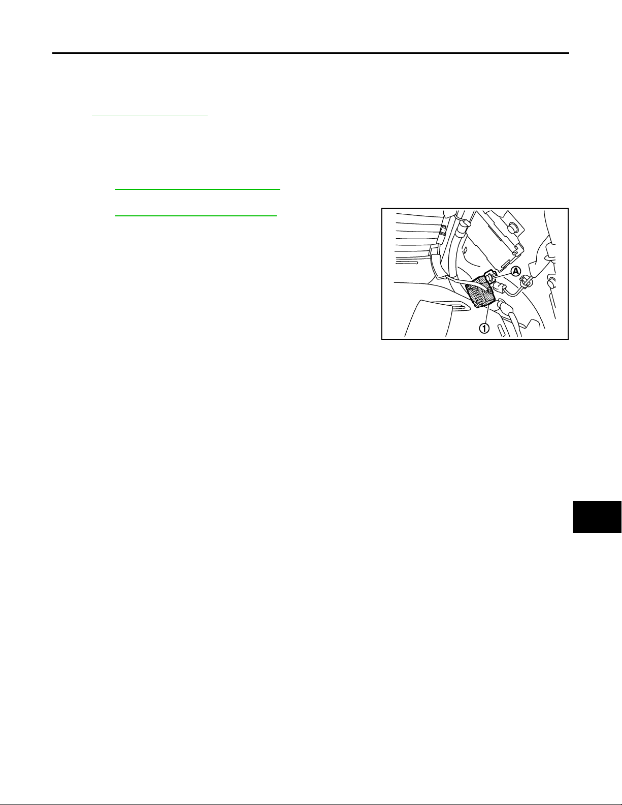
< ON-VEHICLE REPAIR >
2007 G35 Sedan
Revision: October 2006
CONDENSER
CONDENSER
Exploded View INFOID:0000000000962719
Refer toINT-13, "Exploded View".
Removal and Installation INFOID:0000000000962720
REMOVAL
1. Remove the rear seat cushion and the rear seat back.
Refer to SE-105, "
2. Remove the rear kickplate, rear wheel well garnish and the rear pillar finisher.
Refer to INT-13, "
3. Remove bolt (A), and then remove condenser (1) from the vehicle body.
INSTALLATION
Install in the reverse order of removal.
Removal and Installation".
Removal and Installation".
JMLIA0013ZZ
A
B
C
D
E
F
G
H
I
J
K
DEF
M
N
O
P
DEF-61
 Loading...