

Page 1
Data Sheet
December 2000
D372-Type Digital Uncooled DFB
Laser Module for 2.5 Gbits/s Applications
Applications
■
SONET OC-48/STM-16 systems
■
Telecommunications
■
Secure digital data systems
The low-profile D372-Type Laser Module is ideally suited for
OC-48 SONET and other high-speed digital applications.
Features
8-pin package suitable for SONET applications
■
Narrow linewidth, distributed feedback, multiquan-
■
tum-well (DFB-MQW)1.3 µ m laser with singlemode fiber pigtail
■
Choice of wide operating temperature ranges:
–40 ° C to +85 ° C or 0 ° C to +85 ° C
No TEC required
■
High output power: typical 2.0 mW peak power
■
coupled into single-mode fiber
■
Hermetically sealed active components
Internal back-facet monitor
■
Built-in thermistor and bias T
■
■
25 Ω input impedance
Internal isolator
■
Qualification program:
■
TA-983
Telcordia Technologies
*
Benefits
Easily board mounted
■
Gull wing leads
■
No additional heat sinks required
■
Low-cost alternative to industry-standard, 14-pin
■
isolated laser module (ILM)
Highly efficient DFB-MQW laser structure allows
■
for lower threshold and drive currents , and reduced
power consumption
Description
The D372-type uncooled laser module consists of a
laser diode coupled to a single-mode fiber pigtail.
The device is available in a standard, 8-pin configuration (see Figure 1 and/or Table 1) and is ideal for
long-reach (SONET) and other high-speed digital
applications.
The module includes a narrow linewidth (<1 nm),
DFB-MQW single-mode laser and an InGaAs PIN
photodiode back-facet monitor in a hermetically
sealed package.
This package is optimized for a 25 Ω input impedance and allows for dc biasing through an internal
bias T. A thermistor has been included for feedback
to board-level bias circuitry, if needed.
*
T elcordia Technologies
Technologies, Inc.
is a registered trademark of Telcordia
Page 2
°
°
D372-Type Digital Uncooled DFB Data Sheet
Laser Module for 2.5 Gbits/s Applications December 2000
Description
(continued)
The device characteristics listed in this document are
met at 2.0 mW output power. Higher- or lower-power
operation is possible. Under conditions of a fixed
photodiode current, the change in optical output is typically ± 0.5 dB over an operating temperature range of
–40 ° C to +85 ° C.
This device incorporates the new laser 2000 manufacturing process from the Optoelectronic Products unit of
Agere Systems Inc.. Laser 2000 is a low-cost platform
that targets high-volume manufacturing and tighter
product distributions on all optical subassemblies. This
platform incorporates an advanced optical design that
is produced on one of the highly automated production
lines at the Opotelectronic manufacturing facility. The
laser 2000 platform is qualified for the central office and
uncontrolled environments, and can be used for applications requiring high performance and low cost.
43 12
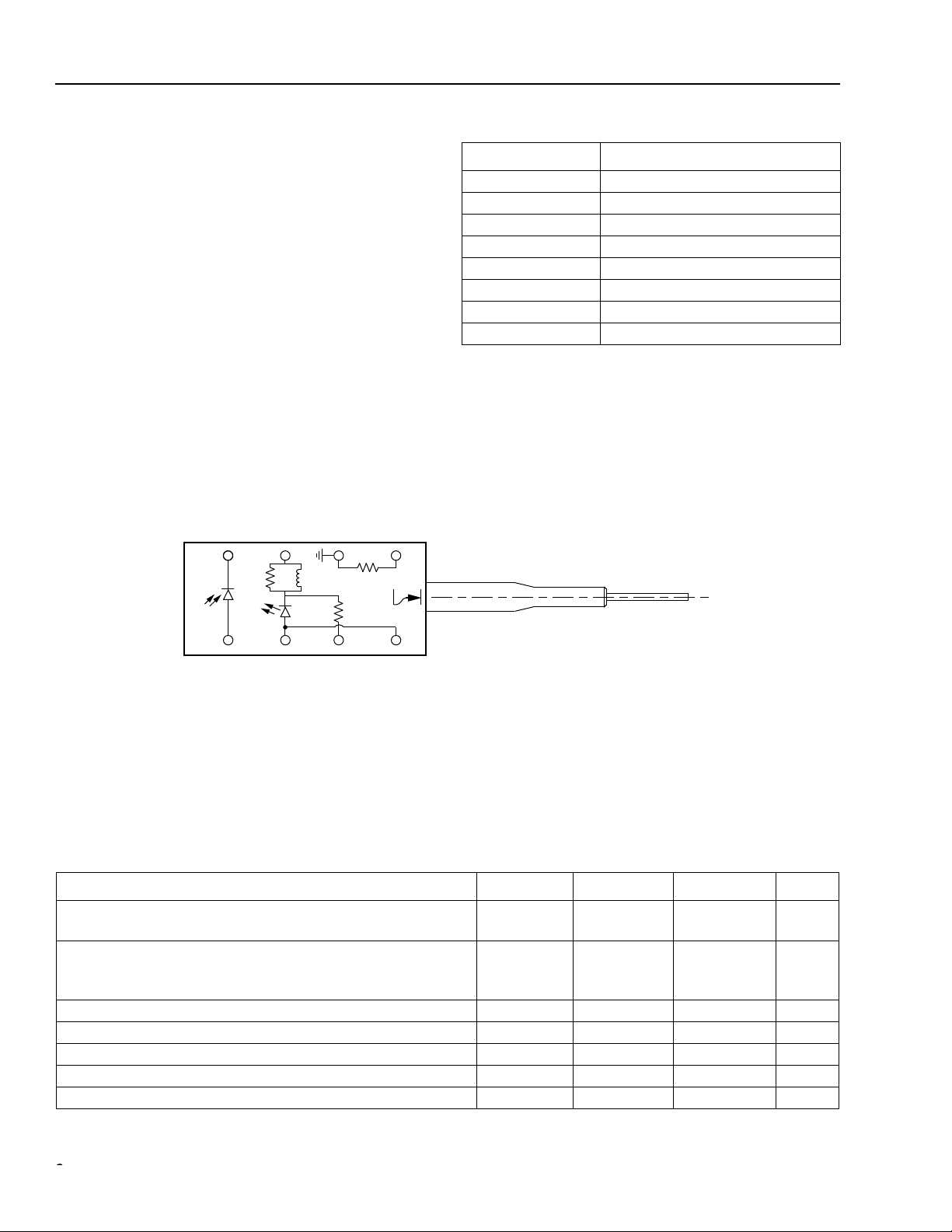
Table 1. Pin Descriptions
Pin Number Connection
1 Thermistor
2 Thermistor, package GND
3 Laser dc bias cathode (–) choke
4 Photodiode cathode
5 Photodiode anode
6 Laser diode anode (+)
7 Laser RF input cathode (–) 25 Ω
8 Laser diode anode (+)
56 87
1-900.b
Figure 1. D372-Type Digital Uncooled DFB Mini 8-Pin Laser Module Schematic, Top View
Absolute Maximum Ratings
Stresses in excess of the absolute maximum ratings can cause permanent damage to the device. These are absolute stress ratings only. Functional operation of the device is not implied at these or any other conditions in excess
of those given in the operations sections of the data sheet. Exposure to absolute maximum ratings for extended
periods can adversely affect device reliability.
Parameter Symbol Min Max Unit
Maximum Peak Laser Drive Current or
Maximum Fiber Power*
Peak Reverse Laser Voltage:
Laser
Monitor
Monitor Forward Current I
Operating Case Temperature Range T
Storage Case Temperature Range T
Lead Soldering Temperature/Time — — 260/10 ° C/s
Relative Humidity (noncondensing) RH — 85 %
* Rating varies with temperature.
I
OP
MAX
P
RL
V
V
RD
FD
C
stg
—
—
—
—
150
10
2
20
mA
mW
V
V
—2mA
–40 85
–40 85
C
C
22
Agere Systems Inc.
Page 3
°
∆λ
Ω
µ
Data Sheet D372-Type Digital Uncooled DFB
December 2000 Laser Module for 2.5 Gbits/s Applications
Handling Precautions
Caution: This device is susceptible to damage as a result of electrostatic discharge (ESD). Take proper
precautions during both handling and testing. Follow guidelines such as JEDEC Publication No.
108-A (Dec. 1988).
Although protection circuitry is designed into the device, take proper precautions to avoid exposure to ESD.
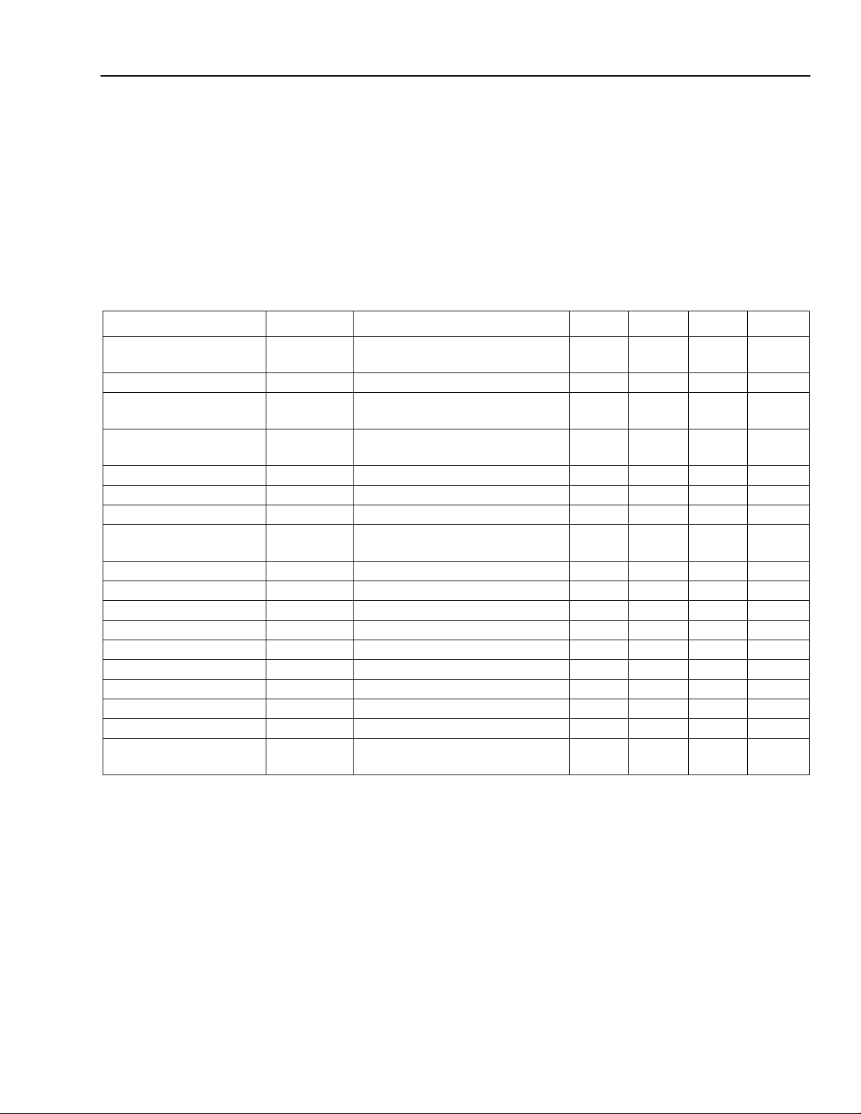
Electrical/Optical Characteristics
Table 2. D372-20 Electrical/Optical Characteristics (over operating temperature range unless otherwise noted)
Parameter Symbol Test Conditions Min Typ Max Unit
Operating Temperature
Range
Optical Output Power P
Threshold Current I
Modulation Current I
Slope Efficiency* SE CW, P
Center Wav elength
Spectral Width (–20 dB)
Side-mode Suppression
Ratio
Tracking Error TE I
Spontaneous Emission P
Rise/Fall Times t
Dispersion Penalty D
Optical Return Loss ORL CW 18 — — dB
Forward Voltage V
Input Impedance R — — 25 —
Monitor Current I
Monitor Dark Current I
Wav elength Tempera-
ture Coefficient
* The slope efficiency is used to calculate the modulation current for a desired output power. This modulation current plus the threshold current
comprise the total operating current for the device.
† Corrected for electrical pulse fall time.
‡ V
= reverse voltage.
R
T — –40 — 85
F
TH
MOD
CW, P
CW, I
C
λ
SMSR CW, P
TH
, t
R
MON
D
F
P
F
10%—90% pulse
CW, peak — 2 — mW
T = 25 ° C
T = full range
F
= 2.0 mW, T = 25 ° C
MON
= const.,T = full range
F
= 2.0 mW, T = 25 ° C 61 — 154 µ W/mA
F
P
= 2.0 mW, CW 1280 — 1335 nm
F
P
= 2.0 mW — — 1 nm
F
= 2.0 mW 30 40 — dB
= constant, CW — 0.5 1.25 dB
MON
I = (0.9) I
TH
†
, T = 25 ° C — 0.125 0.150 ns
5
2
13
7.5
11
—
20
—
15
50
33
55
——50
<60 km, 256 ps/nm — — 1.0 dB
At bias coil — 1.1 1.6 V
‡
V
= 5 V 100 — 1000
R
‡
V
= 5 V — 10 200 nA
R
— — — 0.09 0.1 nm/ ° C
C
mA
mA
mA
µ
W
A
Agere Systems Inc.
3
Page 4

D372-Type Digital Uncooled DFB Data Sheet
Laser Module for 2.5 Gbits/s Applications December 2000
∆λ
Electrical/Optical Characteristics
(continued)
Table 3. D372-21 Electrical/Optical Characteristics (over operating temperature range unless otherwise noted)
Parameter Symbol Test Conditions Min Typ Max Unit
Operating Temperature
T—0—85
°
C
Range
Optical Output Power P
Threshold Current I
Modulation Current I
Slope Efficiency* SE CW, P
Center Wav elength
Spectral Width (–20 dB)
Side-mode Suppression
Ratio
Tracking Error TE I
Spontaneous Emission P
Rise/Fall Times t
Dispersion Penalty DP <60 km, 256 ps/nm
F
TH
MOD
CW, P
CW, I
λ
C
SMSR CW, P
CW, peak — 2 — mW
T = 25 ° C
T = full range
= 2.0 mW, T = 25 ° C
F
= const.,T = full range
MON
= 2.0 mW, T = 25 ° C 61 — 154 µ W/mA
F
P
= 2.0 mW, CW 1280 — 1335 nm
F
P
= 2.0 mW — — 1 nm
F
= 2.0 mW
F
5
2
13
7.5
11
—
20
—
15
50
33
55
30 — — dB
(See Reliability Information, below)
MON
= constant, CW — 0.5 1.25 dB
TH
R
, tF 10%—90% pulse†, T = 25 °C — 0.125 0.150 ns
I = (0.9) I
TH
——50
— — 1.0 dB
mA
mA
mA
µ
W
(See Reliability Information, below)
Optical Return Loss ORL CW 18 — — dB
Forward Voltage VF At bias coil — 1.1 1.6 V
Input Impedance R — — 25 — Ω
Monitor Current IMON VR‡ = 5 V 100 — 1000 µA
Monitor Dark Current ID VR‡ = 5 V — 10 200 nA
Wav elength Tempera-
— — — 0.09 0.1 nm/°C
ture Coefficient
* The slope efficiency is used to calculate the modulation current for a desired output power. This modulation current plus the threshold current
comprise the total operating current for the device.
† Corrected for electrical pulse fall time.
‡ V
= reverse voltage.
R
Reliability Information
Note, the D372-21 product does not undergo any routine dynamic testing.
A 2000-piece sample was tested at 2.5 Gbits/s for SMSR at 0 ° C. In that sample, 99.5% of the devices had SMSR
values greater than 30 dB. Within the failures, 90% were for inability to achieve an extinction ration of 10 dB or
more.
Surveillance samples are tested to verify that the failure rate has not changed,
4
Agere Systems Inc.
Page 5

Data Sheet D372-Type Digital Uncooled DFB
December 2000 Laser Module for 2.5 Gbits/s Applications
Qualification Information
The D372-type laser module is scheduled to complete the following qualification tests and meets the intent of
cordia Technologies
ments.
Table 4. D372-Type Laser Module Qualification Test Plan
Qualification Test Conditions Sample Size Reference
Mechanical Shock
Vibration
Solderability
Thermal Shock
Fiber Pull
Accelerated (Biased) Aging
High-temperature Storage
Temperature Cycling
Cyclic Moisture Resistance
Damp Heat
Internal Moisture
Flammability
ESD Threshold
TR-NWT-000468 for interoffice environments and TA-TSY-000983 for outside plant environ-
500 G
20 g, 20 Hz—2,000 Hz
—
Delta T = 100 °C
1 kg; 3 times
85 °C, 5,000 hrs.
85 °C, 2,000 hrs.
500 cycles
10 cycles
40 °C, 95% RH,
1344 hrs.
<5,000 ppm water vapor
—
—
11 MIL-STD-883
Method 2002
11 MIL-STD-883
Method 2007
11 MIL-STD-883
Method 2007
11 MIL-STD-883
Method 2003
11
25
11
11
11
11 MIL-STD-202
11 MIL-STD-883
— TR357
6
Telcordia Technologies
983
Telcordia Technologies
983, Section 5.18
Telcordia Technologies
983
Telcordia Technologies
983, Section 5.20
Telcordia Technologies
983, Section 5.23
Method 103
Method 1018
Section 4.4.2.5
Telcordia Technologies
983, Section 5.22
Tel-
Agere Systems Inc.
5
Page 6

D372-Type Digital Uncooled DFB Data Sheet
Laser Module for 2.5 Gbits/s Applications December 2000
Outline Diagram
Dimensions are in inches and (millimeters).Laser Safety Information
0.300 (7.62)
0.100 (2.54)
TRADEMARK, CODE, LASER SERIAL NUMBER,
0.169 (4.30)
0.29 (7.37)
AND/OR DATE CODE IN APPROXIMATE AREA SHOWN
0.169 (4.30)
0.20 (5.00)
0.02 (0.50)
0.52 (13.21)
1.06 (27.0)
MIN
39.37 (1000) MIN
(PIGTAIL LENGTH)
0.045 (1.143)
0.17
(4.32)
1.925.e
6
Agere Systems Inc.
Page 7

Data Sheet D372-Type Digital Uncooled DFB
December 2000 Laser Module for 2.5 Gbits/s Applications
Class IIIb Laser Product
FDA/CDRH Class IIIb laser product. All versions are Class IIIb laser products per CDRH, 21 CFR 1040 Laser
Safety requirements. All versions are Class 3B laser products per
IEC
* 60825-1:1993. The device has been classi-
fied with the FDA under accession number 8720010.
This product complies with 21 CFR 1040.10 and 1040.11.
8.3 µm single-mode pigtail or connector
Wavelength = 1.3 µm
Maximum power = 10 mW
Because of size constraints, labeling is not affixed to the module but attached to the outside of the shipping carton.
Product is not shipped with power supply.
Caution: Use of controls, adjustments, and procedures other than those specified herein may result in
hazardous laser radiation exposure.
DANGER
INVISIBLE LASER RADIATION
IS EMITTED FROM THE END
OF FIBER OR CONNECTOR
Avoid direct exposure to beam
Do not view beam directly with
optical instruments
INVISIBLE LASER RADIATION EMITTED FROM END OF FIBER OR CONNECTOR
Avoid exposure to beam
Class 3B Laser Product IEC-60825M 1993 Max. Output: 10 mW Wavelength: 1.3 µm
*
IEC
is a registered trademark of The International Electrotechnical Commission.
Agere Systems Inc.
7
Page 8

D372-Type Digital Uncooled DFB Data Sheet
Laser Module for 2.5 Gbits/s Applications December 2000
Ordering Information
Table 5. D372-20 Ordering Information
Device Code* Comcode Pfiber Connector
D372-20AS 108088048 2.0 mW SC-PC
D372-20BS 108224973 2.0 mW SC-APC
D372-20FS 108130469 2.0 mW FC-PC
D372-20GS 108332032 2.0 mW FC-APC
* Trailing S in code indicates that the module contains an isolator.
Table 6. D372-21 Type Ordering Information
Device Code* Comcode Pfiber Connector
D372-21AS 108898073 2.0 mW SC-PC
D372-21BS 108898081 2.0 mW SC-APC
D372-21FS 108898099 2.0 mW FC-PC
D372-21GS 108898107 2.0 mW FC-APC
D372-21SS 108898114 2.0 mW FC-APC
* Trailing S in code indicates that the module contains an isolator.
For additional information, contact your Agere Systems Account Manager or the following:
INTERNET: http://www.agere.com
E-MAIL: docmaster@micro.lucent.com
N. AMERICA: Agere Systems Inc., 555 Union Boulevard, Room 30L-15P-BA, Allentown, PA 18109-3286
ASIA PACIFIC: Agere Systems Singapore Pte. Ltd., 77 Science Park Drive, #03-18 Cintech III, Singapore 118256
CHINA: Agere Systems (Shanghai) Co., Ltd., 33/F Jin Mao Tower, 88 Century Boulevard Pudong, Shanghai 200121 PRC
JAPAN: Agere Systems Japan Ltd., 7-18, Higashi-Gotanda 2-chome, Shinagawa-ku, Tokyo 141, Japan
EUROPE: Data Requests: DATALINE: Tel. (44) 7000 582 368, FAX (44) 1189 328 148
Agere Systems Inc. reserves the right to make changes to the product(s) or information contained herein without notice. No liability is assumed as a result of their use or application.
Copyright © 2001 Agere Systems Inc.
All Rights Reserved
December 2000
DS01-020OPTO (Replaces DS99-023LWP)
1-800-372-2447, FAX 610-712-4106 (In CANADA: 1-800-553-2448, FAX 610-712-4106)
Tel. (65) 778 8833, FAX (65) 777 7495
Tel. (86) 21 50471212, FAX (86) 21 50472266
Tel. (81) 3 5421 1600, FAX (81) 3 5421 1700
Technical Inquiries: OPTOELECTRONICS MARKETING: (44) 1344 865 900 (Ascot UK)
 Loading...