

Page 1
Data Sheet
Conexant
Doc. No. 101361A
Proprietary Information December 1, 2000
FM336Plus
V.34/Group 3 High Performance Fax Modem Family
The Conexant™ FM336Plus High Performance Fax Modem family offers
ITU-T V.34 half-duplex mode operation that supports synchronous Group 3
facsimile send and receive speeds up to 33600 bits per second (bps).
The FM336Plus-D and FM336Plus-D90 support ITU-T V.34 duplex data
and synchronous/asynchronous modes with rates up to 33600 bps. The
FM336Plus-D90 also supports ITU-T V.90 PCM mode, which can receive
data at speeds up to 56 kbps.
The device has low voltage operation and is housed in a 100-pin Plastic Quad
Flat Package (PQFP). The modem’s small size and low power consumption
allow the design of compact system enclosures for use in industrial, office, and
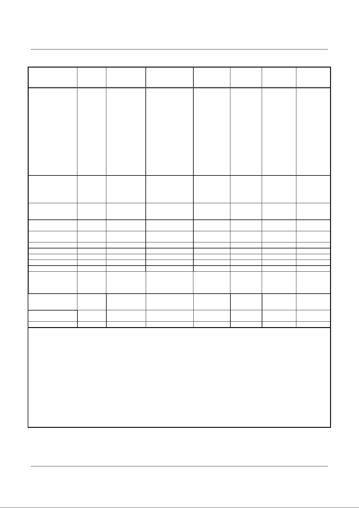
home environments. Table 1 lists the FM336Plus Modem Family models and
features.
Utilizing V.34 and V.90 techniques to optimize modem configuration for line
conditions, the modem connects at the optimal selected data rate that the
channel can support from 2400 bps up to 56000 bps. The modem can operate
over the Public Switched Telephone Network (PSTN) through a line terminator
provided by a Data Access Arrangement (DAA).
The FM336Plus is backward pin compatible with the previous Conexant FM336
fax modem, and supports all features of the FM336 family. The FM336Plus also
has numerous feature and performance enhancements. For more information
on the enhancements, refer to the FM336Plus High Performance Fax Modem
Designer’s Guide (document 101360).
Table 1. FM336Plus Modem Family Models and Features
Clock InputModem Model Part
Number
V.34
Fax
Data
Mode
(–D)
V.90 PCM
Mode
(-D90)
Oscillator
Clock
Crystal
Clock
FM336Plus CX06832-11 Yes No No Yes No
FM336Plus CX06832-12 Yes No No No Yes
FM336Plus-D CX06832-13 Yes Yes No Yes No
FM336Plus-D CX06832-14 Yes Yes No No Yes
FM336Plus-D90 CX06832-15 Yes Yes Yes Yes No
FM336Plus-D90 CX06832-16 Yes Yes Yes No Yes
Features
(Entire FM336Plus Family)
• 2-wire half-duplex fax modem modes
with send and receive data rates up to
33600 bps
− V.34 half-duplex, V.17, V.33, V.29,
V.27 ter, and V.21 channel 2
− Short train option in V.17 and
V.27 ter
• 2-wire duplex data modem modes
− V.21, V.23 (75 bps TX/1200 bps RX
or 1200 bps TX/75 bps RX)
• PSTN session starting
− V.8 and V.8bis signaling
• HDLC support at all speeds
− Flag generation, 0-bit stuffing, ITU
CRC-16 or CRC-32 calculati on and
generation
− Flag detection, 0 bit deletion, ITU
CRC-16 or CRC-32 check sum
error detection
− FSK flag pattern detection during
high-speed receiving
• Tone modes and features
− Programmable single or dual tone
generation
− DTMF receiver
− Tone detection with three
programmable tone detectors
• Serial synchronous data
• Parallel synchronous data
• Automatic Rate Adaptation (ARA) in
V.34 half-duplex
• Auto-dial and auto-answer control
• TTL and CMOS compatible DTE
interface
− ITU-T V.24 (EIA/TIA-232-E)
(data/control)
− Microprocessor bus
(data/configuration/control)
• Receive dynamic range:
− 0 dBm to –43 dBm for V.17, V.33,
V.29, V.27 ter and V.21
− –9 dBm to –43 dBm for V.34 half-
duplex
• Quick Start for V.34 half-duplex
(Conexant Proprietary)
• Caller ID Demodulation
• Call Waiting Detector
• ADPCM Voice Mode
Page 2

FM336Plus V.34/Group 3 High Performance Fax Modem Family
2
Conexant
101361A
Features
(Entire FM336Plus Family
−−−−
Continued)
• Programmable RLSD turn-on and turn-off thresholds
• Programmable transmit level: 0 to –15 dBm
• Adjustable speaker output to monitor received signal
• DMA support for interrupt lines
• Two 16-byte FIFO data buffers for burst data transfer with extension
up to 255 bytes
• Diagnostic capability
• V.21 Channel 1 Flag detect
• V.21 Channel 2 Flag detect
• +3.3 V operation with +5 V tolerant inputs
• +5 V analog signal interface
• 100-pin PQFP package
• Typical power consumption
− Sleep mode: 20 mW
− Normal mode: 250 mW
Distinguishing Features (-D / -D90)
• 2-wire duplex data modem modes with send and receive rates up to
33600 bps
− V.34 (33.6 kbps), V.32 bis, V.32, V.22 bis, and V.22
− Bell 212A and 103
• Serial asynchronous data
• Parallel asynchronous data
• In-band secondary channel (V.34 and V.32 bis)
• Automatic Rate Adaptation (ARA) in V.34 duplex and V.32 bis
• Automatic Mode Selection (AMS)
• Digital near-end and far-end echo cancellation
• Bulk delay for satellite transmission
• Receive dynamic range:
− –9 dBm to –43 dBm for V.34, V.32 bis, V.32, V.22 bis, V.22, and V.23
• 511 pattern generation/detection
• V.13 signaling
• Diagnostic capability
− V.54 inter-DCE signaling
− V.54 local analog and remote digital loopback
Distinguishing Features
(-D90 only)
• 2-wire duplex data modem modes
with receive data rates up to 56 kbps
and send data rates as specified in
the V.34 specification
− V.90 PCM mode
Copyright © 2000, Conexant Systems, Inc., All Rights Reserved.
Information in this document is provided in connec tion with Conexant Systems, Inc . ("Conexant") products. These materials are provided by
Conexant as a service to its customers and may be used for informat ional purposes only. Conexant assumes no responsibilit y f or errors or
omissions in these materials. Conexant may make changes to speci fications and product descriptions at any time, without notice. Conexant
makes no comm i tment to update the information contained herein. Conexant shall have no responsibility whatsoever for conflicts or
incompatibilities arising from f uture changes to its specificat ions and product descriptions.
No license, express or impli ed, by estoppel or otherwise, to any intellectual property rights is grant ed by this document. Except as provided in
Conexant’s Terms and Conditions of Sale for s uch products, Conexant assumes no liabilit y whatsoever.
THESE MATERIALS ARE PROVIDED "AS IS" WITHOUT WARRANTY OF ANY KIND, EITHER EXPRESS OR IMPLIED, RELATING TO
SALE AND/OR USE OF CONEXANT PRODUCT S INCLUDING LIABILITY OR WARRANTIES RELATING TO FITNESS FOR A
PARTICULAR PURPOSE, MERCHANTABILITY, OR INF RI NGEMENT OF ANY PATENT, COP YRIGHT OR OTHER INTELLECTUAL
PROPERTY RIGHT. Conexant further does not warrant the ac curacy or completeness of the information, text, graphi cs or other items
contained within these materi al s. Conexant shall not be liable for any spec i al , indirect, incidental, or consequential damages, i ncluding without
limitation, lost revenues or lost profits, which may result from the use of these materials.
Conexant products are not intended for use in medical, life saving or l i fe sustaining applicati ons. Conexant customers usi ng or s elling
Conexant products for use in such appli cations do so at their own risk and agree t o fully indemnify Conexant for any damages resulting from
such improper use or sale.
The following are trademarks of Conexant Systems, Inc.: Conexant, t he Conexant C s ymbol, and “What’ s Next in Communications
Technologies.” Product names or services list ed i n this publication are for ident i fication purposes only, and may be trademarks of third
parties. Third-party brands and names are the property of their respective owners.
Reader Response:
Conexant strives to produce quality documentation and welcomes your feedback. Please send
comments and suggestions to conexant.tech.pubs@conexant.com. For technical questions, contact your local Conexant
sales office or field applications engineer.
Page 3

V.34/Group 3 High Performance Fax Modem Family FM336Plus
101361A
Conexant
3
GROUP3 FACSIMILE MODEM
(ENTIRE FM336PLUS FAMILY)
The modem satisfies the requirements specified in
ITU-T recommendations V.34 half-duplex, V.17, V.33,
V.29, V.27 ter, V.21, and meets the binary signaling
requirements of V.8 and T.30 with Annex F.
Internal HDLC support eliminates the need for an
external serial input/output (SIO) device in the DTE for
products incorporating error detection and T.30
protocol. The modem can perform HDLC framing per
T.30 at all data speeds. CRC generation/checking
along with zero insertion/deletion enhances
SDLC/HDLC frame operations. Two FSK (V.21 Ch. 1
and V.21 Ch. 2) flag pattern detectors facilitate FSK
detection during high-speed reception. The modem
features a programmable DTMF transmitter/receiver
and three programmable tone detectors.
DUPLEX DATA MODE (-D / -D90)
The duplex data mode supports Internet facsimile
applications. The modem can connect at the highest
data rate up to 33600 bps with auto fall back to
V.32 bis. The FM336Plus-D and FM336Plus-D90
modems satisfy the requirements specified in ITU-T
recommendations V.34, V.32 bis, V.32, V.22 bis, V.22,
V.23, V.21, Bell 212A, and Bell 103.
ITU-T V.90 PCM MODE (-D90)
The ITU-T V.90 PCM mode can receive data at
speeds up to 56 kbps from a digitally connected V.90
central site modem. The FM336Plus-D90 takes
advantage of the PSTN which is primarily digital to the
central office local loop (except for the client modem)
and is ideal for applications such as remote access to
an Internet Service Provider (ISP), online service, or
corporate intranet. The modem can send upstream
data at speeds up to the V.34 rate.
TECHNICAL SPECIFICATIONS
The FM336Plus modem provides the processing core
for a complete facsimile modem design.
Configurations and Rates
The selectable modem configurations, signaling rates,
and data rates are listed in Table 2.
Automatic Mode Selection (-D / -D90)
When Automatic Mode Selection (AMS) is enabled,
the modem configures itself to the highest compatible
data rate supported by the remote modem. Automode
operation is supported in V.90 (-D90 only), V.34,
V.32 bis, V.32, V.22 bis, V.22, V.21, V.23, Bell 212A,
and Bell 103 modes.
Automatic Rate Adaptation
In V.34 duplex, V.34 half-duplex, and V.32 bis modes,
Automatic Rate Adaptation (ARA) can be enabled to
select the optimal highest acceptable data rate based
on the Eye Quality Monitor (EQM). This selection
occurs during startup.
Two ARA modes are available. ARA in ROM is an
adaptive selection made by the modem based upon a
fixed ROM table. ARA in RAM is based on the host
programmable RAM table and can be changed by the
user.
Data Encoding
The data encoding conforms to ITU-T recommendations
V.90 (-D90 only), V.34, V.32 bis, V.32, V.17, V.33,
V.29, V.27 ter, V.22 bis, V.22, V.23, or V.21, and is
compatible with Bell 208, 212A, or 103, depending on
the configuration.
Tone Generation
The modem can generate single or dual voice-band
tones from 0 Hz to 3600 Hz with a resolution of
0.15 Hz and an accuracy of ± 0.01%. Tones over
3000 Hz are attenuated. DTMF tone generation allows
the modem to operate as a programmable DTMF
dialer.
Page 4

FM336Plus V.34/Group 3 High Performance Fax Modem Family
4
Conexant
101361A
Supervisory Tone Detection
Three parallel tone detectors (A, B, and C) are
provided for supervisory tone detection. The signal
path to these detectors is separate from the main
received signal path.
Each tone detector consists of two cascaded second
order IIR biquad filters. The coefficients are host
programmable. Each fourth order filter is followed by a
level detector which has host programmable turn-on
and turn-off thresholds allowing hysteresis. A pre-filter
and squarer precede tone detector C. This circuit is
useful for detecting a tone with a frequency equal to
the difference between two tones that may be
simultaneously present on the line. The SQDIS bit may
disable the squarer causing tone detector C to be an
eight-order filter. The tone detectors are disabled in
data mode.
The tone detection sample rate is 9600 Hz in V.8 and
V.34 modes and is 7200 Hz in non-V.34 modes. The
default call progress filter coefficients are based on a
7200 Hz sampling rate and apply to non-V.34 modes
only. The maximum detection bandwidth is equal to
one-half the sample rate.
Auto-Dialing and Auto-Answering Control
Features are provided to allow the host to perform
auto-dialing and auto-answering. These functions
include DTMF or pulse dialing, ring detection, and a
comprehensive supervisory tone detection scheme.
The major control parameters are host programmable.
Transmitted Data Spectrum
The transmitter spectrum is shaped by raised cosine
filter functions, either the square root of 12.5% (V.34,
V.32 bis, V.32), 20% (V.17, V.33, and V.29), 50%
(V.27 ter, Bell 208), or 75% (V.22 bis, Bell 212A).
Transmit Level
The transmitter output level is selectable from 0 dBm
to –15 dBm in 1 dB steps and is accurate to ±0.5 dB
when used with an external hybrid. The output level
can also be tuned by changing a gain constant in the
modem DSP RAM. The maximum V.34 transmit level
for acceptable receive performance should not exceed
–9 dBm.
Answer Tone (-D / -D90)
When the NV25 bit is a zero, the modem generates
a 2100 Hz answer tone at the beginning of the answer
handshake for 5.0 seconds (V.8) or 3.6 seconds
(V.32 bis, V.32, V.22 bis, V.22, V.23, and V.21). The
answer tone has 180° phase reversals every 0.45
seconds to disable network echo cancellers (V.8,
V.32 bis, and V.32).
Receive Level
The modem satisfies performance requirements for
received line signal levels from 0 dBm to –43 dBm
measured at the receiver analog (TIP and RING) input
in V.17, V.33, V.29, V.27 ter, and DTMF modes. In
V.90, V.34, V.32 bis, V.32, V.22 bis, V.22, and
V.23 modes, the receive level range is from –9 dBm
(–15 dBm at RIN) to –43 dB. (RIN is 6 dB lower than
TIP and RING.)
Carrier Recovery
The carrier recovery circuit can track a ±7 Hz
frequency offset in the received carrier.
Echo Canceller (-D / -D90)
A data echo canceller with near-end and far-end echo
cancellation is included for 2-wire duplex V.90/V.34/
V.32 bis/V.32 operation. The combined echo span of
near and far cancellers can be up to 40 ms. The
proportion allotted to each end is automatically
determined by the modem. The delay between nearend and far-end echoes can be up to 1.2 seconds.
Page 5
V.34/Group 3 High Performance Fax Modem Family FM336Plus
101361A
Conexant
5
Table 2. Configurations, Signaling Rates, and Data Rates
Configuration Modulation Carrier
Frequency (Hz)
±0.01%
Data Rate (bps)
±0.01%
Symbol Rate
(Symbols/Sec)
Bits/Symbol
Data
Bits/Symbol
TCM
Constellation
Points
V.90 PCM PCM — 56000 R/V.34 rates T
(Note 4)
8000 Dynamic — —
V.34 33600 TCM** TCM Note 2 33600 3429 only Note 2 Note 2 Note 2
V.34 31200 TCM** TCM Note 2 31200 3200 min Note 2 Not e 2 Note 2
V.34 28800 TCM** TCM Note 2 28800 3000 min Note 2 Not e 2 Note 2
V.34 26400 TCM** TCM Note 2 26400 2800 min Note 2 Not e 2 Note 2
V.34 24000 TCM** TCM Note 2 24000 2800 min Note 2 Not e 2 Note 2
V.34 21600 TCM** TCM Note 2 21600 2400 min Note 2 Not e 2 Note 2
V.34 19200 TCM** TCM Note 2 19200 Note 2 Note 2 Note 2 Note 2
V.34 16800 TCM** TCM Note 2 16800 Note 2 Note 2 Note 2 Note 2
V.34 14400 TCM** TCM Note 2 14400 Note 2 Note 2 Note 2 Note 2
V.34 12000 TCM** TCM Note 2 12000 Note 2 Note 2 Note 2 Note 2
V.34 9600 TCM** TCM Note 2 9600 Note 2 Note 2 Note 2 Note 2
V.34 7200 TCM** TCM Note 2 7200 Note 2 Note 2 Note 2 Note 2
V.34 4800 TCM** TCM Note 2 4800 Note 2 Note 2 Note 2 Note 2
V.34 2400 TCM** TCM Note 2 2400 2400 only Note 2 Note 2 Note 2
V.32 bis 14400 TCM TCM 1800 14400 2400 6 1 128
V.32 bis 12000 TCM TCM 1800 12000 2400 5 1 64
V.32 bis 9600 TCM TCM 1800 9600 2400 4 1 32
V.32 bis 7200 TCM TCM 1800 7200 2400 3 1 16
V.32 bis 4800 QAM 1800 4800 2400 2 0 4
V.32 9600 TCM TCM 1800 9600 2400 4 1 32
V.32 9600 QAM 1800 9600 2400 4 0 16
V.32 4800 QAM 1800 4800 2400 2 0 4
V.22bis 2400 QAM 1200/2400 2400 600 4 0 16
V.22bis 1200 DPSK 1200/2400 1200 600 2 0 4
V.22 1200 DPSK 1200/2400 1200 600 2 0 4
V.22 600 DPSK 1200/2400 600 600 1 0 4
V.23 1200/75 FSK 1700/420 1200/75 1200 1 0 —
V.21 FSK 1080/1750 Up to 300 300 1 0 —
Bell 208 4800 DPSK 1800 4800 1600 3 0 8
Bell 212A DPS K 1200/2400 1200 600 2 0 4
Bell 103 FSK 1170/2125 Up to 300 300 1 0 —
V.17 14400 TCM/V.33 TCM 1800 14400 2400 6 1 128
V.17 12000 TCM/V.33 TCM 1800 12000 2400 5 1 64
V.17 9600 TCM TCM 1800 9600 2400 4 1 32
V.17 7200 TCM TCM 1800 7200 2400 3 1 16
V.29 9600 QAM 1700 9600 2400 4 0 16
V.29 7200 QAM 1700 7200 2400 3 0 8
V.29 4800 QAM 1700 4800 2400 2 0 4
V.27 ter 4800 DP S K 1800 4800 1600 3 0 8
V.27 ter 2400 DP S K 1800 2400 1200 2 0 4
V.21 Channel 2 FSK 1750 300 300 1 0 —
Notes:
1. Modulation legend:
TCM: Trellis-Coded Modulation
QAM: Quadrature Amplitude Modulation
PCM: Pulse Coded Modulation
FSK: Frequency Shift Keying
DPSK: Differential Phase Shift Keying
2. Adaptive; established duri ng handshake:
Symbol Rate (Baud) V.34 Low Carrier Frequency (Hz) V.34 High Carrier Frequency (Hz)
2400 1600 1800
2800 1680 1867
3000 1800 2000
3200 1829 1920
3429 1959 1959
3. ** For both duplex and half-duplex modes.
4. Maximum data rate.
Page 6

V.34/Group 3 High Performance Fax Modem Family FM336Plus
101361A
Conexant
6
Data Formats
Serial Synchronous Data
•
Data rate: 300–56000 bps (-D90) or
300–33600 bps ±0.01%
•
Selectable clock: Internal, external, or slave
Serial Asynchronous Data (-D / -D90)
•
Data rate: 300–56000 bps (-D90) or
300–33600 bps +1%/–2.5% or +2.3%/–2.5%; up to
300 bps (V.21 and Bell 103); 1200/75 bps (V.23)
•
Data bits per character: 7, 8, 9, 10, or 11
Parallel Synchronous Data
•
Normal sync: 8-bit data for transmit and receive
•
Data rate: 300–56000 bps (-D90) or
300–33600 bps ±0.01%
•
SDLC/HDLC support:
−
Transmitter: Flag generation, 0-bit stuffing,
CRC-16 or CRC-32 generation
−
Receiver: Flag detection, 0-bit deletion, CRC-16
or CRC-32 checking
Parallel Asynchronous Data (-D / -D90)
•
Data rate: 300–56000 bps (-D90) or
300–33600 bps +1%/–2.5% or +2.3%/–2.5%;
1200, 300, or 75 bps (FSK)
•
Data bits per character: 5, 6, 7, or 8
•
Parity generation/checking: Odd, Even,
or 9th data bit
Async/Sync and Sync/Async Conversion
(-D / -D90)
An asynchronous-to-synchronous converter is provided
in the transmitter and a synchronous-to-asynchronous
converter is provided in the receiver. The converters
operate in both serial and parallel modes. The
asynchronous character format is 1 start bit, 5 to 8
data bits, an optional parity bit, and 1 or 2 stop bits.
Valid character size, including all bits, is 7, 8, 9, 10, or
11 bits per character. Two ranges of signaling rates
are provided:
•
Basic range: +1% to –2.5%
•
Extended overspeed range: +2.3% to –2.5%
When the transmit converter is operating at the basic
signaling rate, no more than one stop bit will be deleted
per eight consecutive characters. When operating at
the extended rate, no more than one stop bit will be
deleted per four consecutive characters. Break
handling is performed as described in V.14.
Asynchronous characters are accepted on the TXD
serial input and are issued on the RXD serial output.
V.54 Inter-DCE Signaling (-D / -D90)
The modem supports V.54 inter-DCE signaling
procedures in synchronous and asynchronous
configurations. Transmission and detection of the
preparatory, acknowledgment, and termination phases
as defined in V.54 are provided. Three control bits
(V54T, V54A, and V54P) in the transmitter allow the
host to send the appropriate bit patterns. Three control
bits (V54TE, V54AE, and V54PE) in the receiver are
used to enable one of three bit pattern detectors. A
status bit (V54DT) indicates when the selected pattern
detector has found the corresponding bit pattern.
V.13 Remote RTS Signaling (-D / -D90)
The modem supports V.13 remote RTS signaling.
Transmission and detection of signaling bit patterns in
response to a change of state in the RTS bit or the
/RTS input signal are provided. This feature may be
used to clamp/unclamp the local /RLSD and RXD
signals in response to a change in the remote /RTS
signal in order to simulate controlled carrier operation
in a constant carrier environment. The modem
automatically clamps and unclamps /RLSD.
In-Band Secondary Channel (-D / -D90)
A duplex in-band secondary channel is provided in
V.34 (all speeds) and V.32 bis/V.32 (7200 bps and
above) modes. The secondary channel operates in
parallel data mode with independent transmit and
receive interrupts and data buffers. The main channel
may operate in parallel or serial mode.
In V.34 modes, the secondary channel rate is 200 bps.
In V.32 bis/V.32 modes, the secondary channel rate
is 150 bps. This rate is also host programmable in
V.32 bis/V.32 modes.
Transmit and Receive FIFO Data Buffers
Two 16-byte first-in first-out (FIFO) data buffers allow
the DTE/host to output up to 16 bytes of transmit data
to the transmitter FIFO (TXFIFO) and input up to
16 bytes of accumulated received data from the
receiver FIFO (RXFIFO). The TXFIFO and RXFIFO
can be extended up to 255 bytes. The size of the FIFO
extension is 255 bytes overall and can be divided
between the two FIFOs in any proportion.
The RXFIFO is always enabled. The host can enable
the TXFIFO. Status bits indicate when the TXFIFO is
not full, the TXFIFO is half-full (eight or more bytes
loaded), the RXFIFO is empty, and the RXFIFO is halffull. An interrupt mask register allows an interrupt
request to be generated whenever the status bits
change state.
Page 7

V.34/Group 3 High Performance Fax Modem Family FM336Plus
101361A
Conexant
7
DMA Support for Interrupt Request Lines
DMA support is available in synchronous data modes.
When DMA support is enabled, the modem /RI and
/DSR lines are assigned to Transmitter Request
(TXRQ) and Receiver Request (RXRQ) hardware
output interrupt request lines, respectively. The TXRQ
and RXRQ signals follow the assertion of the Transmit
Data Buffer Empty (TDBE) and Receive Data Buffer
Full (RDBF) interrupt bits, thereby allowing the
DTE/host to respond immediately to the interrupt
request without masking out status bits to determine
the interrupt source.
Quick Start for V.34 Half-Duplex
(Conexant Proprietary)
V.34 Fax Quick Startup eliminates the V.8 phase 1
segment and uses a shortened training sequence
during phase 3, which can save up to 50% of the initial
Phase1 to Phase 4 start up time for normal V.34 halfduplex connection.
ADPCM Voice Mode
The Adaptive Differential Pulse Code Modulation
(ADPCM) voice coder and decoder (codec)
compresses and decompresses voice signals for
efficient digital storage of voice messages. The codec
operates at 28.8 kbps, 21.6 kbps, or 14.4 kbps
(4-bit, 3-bit, or 2-bit quantization, respectively) with
an 8.0 kHz sampling rate.
Caller ID Demodulation
Caller ID information can be demodulated in the
V.23 1200 receive configuration and presented to the
DTE/host in serial (RXD) or parallel (RBUFFER) form.
Call Waiting Detector
A tone detector is provided to perform call waiting
detection and is available in V.90, V.34, V.32bis, V.32,
V.17, V.29, and V.27ter modes. By default, call waiting
tone levels down to approximately –28 dBm can be
detected. The detector can tolerate near-end echo
levels up to 10 dB above the call waiting tone level.
Telephone Line Interface
Line Transformer Interface.
V.90/V.34 places high
requirements upon the Data Access Arrangement
(DAA) connection to the telephone line. Due to the
wider bandwidth requirement of V.90 and V.34, the
DAA must maintain linearity from 150 to 3950 Hz for
V.34, and from 10 to 4000 Hz for V.90.
Relay Control
. Direct control of the off-hook and
talk/data relays is provided. Internal relay drivers allow
direct connection to the off-hook and talk/data relays.
The talk/data relay output can optionally be used for
pulse dial.
Speaker Interface
. A SPKR output is provided with
on/off and volume control logic incorporated in the
modem, requiring only an external amplifier to drive a
speaker.
Hardware Interface Signals
Figure 1 illustrates the functional interface signals. In
this diagram, an active low signal is indicated by a
forward slash “/” (e.g., /RESET). A clock intended to
activate logic on its rising edge (low-to-high transition)
is called active high (e.g., TDCLK), while a clock
intended to activate logic on its falling edge (high-tolow transition) is called active low (e.g., /RDCLK).
Figure 2 illustrates the modem pin assignments.
Table 3 provides the signal descriptions.
Power and Maximum Ratings
Table 4 lists the current and power requirements.
Table 5 lists the absolute maximum ratings.
Clock Sources
The modem is offered in two configurations depending
upon the selected clock source. One configuration
utilizes a crystal source and the other uses an
oscillator source.
For the crystal configuration, the crystal is connected to
XTLI (pin 85) and XTLO (pin 86). For the oscillator
source, the oscillator is connected to CLKIN (pin 85)
and XTLO (pin 86) is not connected.
Package Dimensions
Figure 3 shows the package dimensions.
Additional Information
Additional design information is described in the
FM336Plus V.34/Group3 High Performance Fax
Modem Designer’s Guide.
Page 8

FM336Plus V.34/Group 3 High Performance Fax Modem Family
8
Conexant
101361A
V.24
Interface
Host
Processor
FM336Plus
Modem Family
Crystal
Power Supply
Speaker
Amplifier
Optional
Eye Pattern
Generator
Line
Interface
/RTS
TXD
/CTS
TDCLK
XTCLK
/RLSD
RXD
/RDCLK
/DTR
/RI*
/DSR**
/RD
/CS
/WR
D7:0
RS4:0
IRQ
/RESET
TXRQ*
RXRQ**
XTL0
XTLI
TXA1
RIN
OH
TXA2
/TALK
RINGD
EYEXY
EYESYNC
EYECLK
+5V
AGND
DGND
SPKR
* Selectable; TXRQ output replaces /RI output.
** Selectable; RXRQ output replaces /DSR output.
TIP
RING
telephone
line
+3.3V
Oscillator
CLKIN
OR
Figure 1. Functional Interface Signals
Page 9

V.34/Group 3 High Performance Fax Modem Family FM336Plus
101361A
Conexant
9
1
2
3
4
5
6
7
8
9
10
11
12
13
14
15
16
17
18
19
20
21
22
23
24
25
26
27
28
29
30
80
79
78
77
76
75
74
73
72
71
70
69
68
67
66
65
64
63
62
61
60
59
58
57
56
55
54
53
52
51
VSS
IRQ
/RTS
RINGD
/RI
/DSR
EYEXY
XCLK
YCLK
VGG
IA_SLEEP
VDD1
/DTR
RXD
RESERVED
VSS
XTCLK
VDD1
VCORE
SR1IO
NC
RESERVED
RESERVED
VDD1
SLEEP
NC
NC
VSS
VSUB
RESERVED
RESERVED
RS2
RS3
RS4
/CS
/WR
/RD
/RDCLK
/RLSD
TDCLK
TXD
/CTS
VDD1
RESERVED
RESERVED
VSS
NC
/RESET
SR4OUT
NC
SR4IN
CLK_OUT
EYESYNC
EYECLK
MAVSS
MAVDD
SPKR
TXA2
TXA1
VREF
PLL_GND
VSS
PLL_VDD
RS1
RS0
D7 D6D5
VDD1D4D3D2D1D0XTALO
XTALI/CLKIN
VDD1
RESERVED
RESERVED
GPO0
VC
RIN
MAVSS
/POR
RESERVED
RESERVED
/TALK
VDD
RESERVED
RESERVED
NC
M_CNTRL_SIN
M_CLKIN
M_TXSIN
M_SCK
M_RXOUT
M-STROBE
RESERVED
OH
VDD
31
32
33
34
35
36
37
38
39
40
41
42
43
44
45
46
47
48
49
50
100
99
98
97
96
95
94
93
92
91
90
89
88
87
86
85
84
83
82
81
Figure 2. FM336Plus Family Modem Pin Assignments—100-Pin PQFP
Page 10

FM336Plus V.34/Group 3 High Performance Fax Modem Family
10
Conexant
101361A
Table 3. Signal Descriptions
Pin Signal Label I/O Type Interface Pin Signal Label I/O Type Interface
1 RESERVED —— 51 RESERVED ——
2 RS2 IA HOST Interface 52 VSUB GND —
3 RS3 IA HOST Interface 53 VSS GND —
4 RS4 IA HOST Interface 54 NC — NC
5 /CS IA HOST Interface 55 NC — NC
6 /WR IA HOST Interface 56 SLEEP MI Modem Interconnect
7 /RD IA HOST Interface 57 VDD1 PWR —
8 /RDCLK OA DTE Serial Interfac e 58 RESERVED ——
9 /RLSD OA DTE Serial Interface 59 RESERVED ——
10 TDCLK OA DTE Serial Interface 60 NC — NC
11 TXD IA DTE Serial Interface 61 SR1IO MI Modem Interconnect
12 /CTS OA DTE Serial Interface 62 VCORE PWR —
13 VDD1 PWR — 63 VDD1 PWR —
14 RESERVED —— 64 XTCLK IA DTE Serial Interface
15 RESERVED —— 65 VSS GND —
16 VSS GND — 66 RESERVED ——
17 NC — NC 67 RXD OA DTE Serial Interface
18 /RESET OA Modem Interconnect 68 /DTR IA DTE Serial Interface
19 SR4OUT OA Modem Interconnect 69 VDD1 PWR —
20 NC — NC 70 IA_SLEEP MI Modem Interconnect
21 SR4IN IA Modem Interconnect 71 VGG PWR —
22 CLK_OUT OA Modem Interconnect 72 YCLK OA Overhead Signal
23 EYESYNC OA Diagnostic Signal 73 XCLK OA Overhead Signal
24 EYECLK OA Diagnostic Signal 74 EYEXY OA Diagnostic Signal
25 MAVSS GND — 75 /DSR OA DTE Serial Interface
26 MAVDD PWR — 76 /RI OA Telephone Line Interface
27 SPKR O(DF) Telephone Line Interface 77 RINGD IA Telephone Line Interface
28 TXA2 O(DD) Telephone Line Interface 78 /RTS IA DTE Serial Interface
29 TXA1 O(DD) Telephone Line Interface 79 IRQ OA HOST Interface
30 VREF MI Modem Interconnect 80 VSS GND —
31 VC MI Modem Interconnect 81 GPO0 MI Modem Interconnect
32 RIN I(DA) Telephone Line Interface 82 RESERVED ——
33 MAVSS AGND — 83 RESERVED ——
34 /POR IA Modem Interconnect 84 VDD1 PWR —
35 RESERVED —— 85 XTALI/CLKIN I Overhead Signal
36 RESERVED —— 86 XTALO O Overhead Signal
37 /TALK O(DD) Telephone Line Interface 87 D0 IA/OB HOST Interface
38 VDD PWR — 88 D1 IA/OB HOST Interface
39 RESERVED —— 89 D2 IA/OB HOST Interface
40 RESERVED —— 90 D3 IA/OB HOST Interface
41 NC — NC 91 D4 IA/OB HOST Interface
42 M_CNTRL_SIN IA Modem Interconnect 92 VDD1 PWR —
43 M_CLKIN IA Modem Interconnect 93 D5 IA/OB HOST Interface
44 M_TXSIN IA Modem Interconnect 94 D6 IA/OB HOST Interface
45 M_SCK IA Modem Interconnect 95 D7 IA/OB HOST Interface
46 M_RXOUT IA Modem Interconnect 96 RS0 IA/OB HOST Interface
47 M_STROBE IA Modem Interconnect 97 RS1 IA/OB HOST Interface
48 RESERVED —— 98 PLL_VDD PWR —
49 OH O(DD) Telephone Line Interface 99 VSS GND —
50 VDD PWR — 100 PLL_GND GND —
Notes
:
1. I/O types:
MI = Modem interconnect
IA, IB = Digital input
OA, OB = Digital output
I(DA) = Analog input
O(DD), O(DF) = Analog output
2. NC = No external connection required
RESERVED = No external connection allowed
3. Interface Legend:
HOST = Modem Control Unit (Host)
DTE = Data Terminal Equipment
Page 11

V.34/Group 3 High Performance Fax Modem Family FM336Plus
101361A
Conexant
11
Table 4. Current and Power Requirements
Current (ID) Power (PD)
Mode
Typical Current
(mA) @ 25° C
Maximum
Current
(mA) @ 0° C
Typical Power
(mW) @ 25° C
Maximum Power
(mW) @ 0° C Notes
Normal mode
76 88 250 320
Sleep mode
6 8 20 30
Note:
Test conditions: VDD = +3.3 VDC for typical values; V DD = +3.63 VDC for maximum values.
Table 5. Absolute Maximum Ratings
Parameter Symbol Limits Units
Supply Voltage
V
DD1
–0.5 to +3.6 V
Digital Input Voltage
V
IND
–0.5 to (+5VD +0.5) V
Operating Temperature Range
T
A
–0 to +70 ° C
Storage Temperature Range
T
STG
–55 to +125 ° C
Analog Input Voltage
V
INA
–0.3 to (+5VA + 0.3) V
Voltage Applied to Outputs i n Hi gh Impedance (Off) State
V
HZ
–0.5 to (+5VD + 0.5) V
DC Input Clamp Current
I
IK
±20 mA
DC Output Clamp Current
I
OK
±20 mA
Static Discharge Vol tage (25 °C)
V
ESD
±2500 V
Latch-up Current (25 °C)
I
TRIG
±200 mA
Page 12

FM336Plus V.34/Group 3 High Performance Fax Modem Family
12
Conexant
101361A
SIDE VIEW
TOP VIEW
e
b
E
D
D1
E1
D2
E2
PD-PQFP-100 (040695)
CHAM (4X)
See detail A
E1
c
A1
A2
DETAIL A
A
L
L1
Millimeters
0.05
22.95
16.95
0.73
0.25
0.13
2.4 MAX
0.35
2.0 REF
23.45
20.0 REF
18.85 REF
17.45
14.0 REF
12.35 REF
1.03
1.6 REF
0.65 BSC
0.45
0.19
0.10 MAX
0.0020
0.9035
0.6673
0.0287
0.0098
0.0051
A
A1
A2
D
D1
D2
E
E1
E2
L
L1
e
b
c
Coplanarity
Min.
Max.
Min.
Max.
Inches
Dim.
Ref: 100-PIN PQFP (GP00-D234)
* Metric values (millimeters) should be used for
PCB layout. English values (inches) are
converted from metric values and may include
round-off errors.
0.0945 MAX
0.0138
0.0787 REF
0.9232
0.7874 REF
0.7421 REF
0.6870
0.5512 REF
0.4862 REF
0.0406
0.0630 REF
0.0256 BSC
0.0177
0.0075
0.004 MAX
PIN 1
REF
Figure 3. Package Dimensions—100-Pin PQFP
Page 13

101361A
Conexant
INSIDE COVER BACK PAGE
Page 14

Further Information
literature@conexant.com
(800) 854-8099 (North America)
(949) 483-6996 (International)
Printed in USA
WorldHeadquarters
Conexant Systems, Inc.
4311 Jamboree Road
Newport Beach, CA
92660-3007
Phone: (949) 483-4600
Fax 1: (949) 483-4078
Fax 2: (949) 483-4391
Americas
U.S. Northwest/
Pacific Northwest – Santa Clara
Phone: (408) 249-9696
Fax: (408) 249-7113
U.S. Southwest – Los Angeles
Phone: (805) 376-0559
Fax: (805) 376-8180
U.S. Southwest – Orange County
Phone: (949) 483-9119
Fax: (949) 483-9090
U.S. Southwest – San Diego
Phone: (858) 713-3374
Fax: (858) 713-4001
U.S. North Central – Illinois
Phone: (630) 773-3454
Fax: (630) 773-3907
U.S. South Central – Texas
Phone: (972) 733-0723
Fax: (972) 407-0639
U.S. Northeast – Massachusetts
Phone: (978) 367-3200
Fax: (978) 256-6868
U.S. Southeast – North Carolina
Phone: (919) 858-9110
Fax: (919) 858-8669
U.S. Southeast – Florida/
South America
Phone: (727) 799-8406
Fax: (727) 799-8306
U.S.Mid-Atlantic– Pennsylvania
Phone: (215) 244-6784
Fax: (215) 244-9292
Canada – Ontario
Phone: (613) 271-2358
Fax: (613) 271-2359
Europe
Europe Central – Germany
Phone: +49 89 829-1320
Fax: +49 89 834-2734
Europe North – England
Phone: +44 1344 486444
Fax: +44 1344 486555
Europe – Israel/Greece
Phone: +972 9 9524000
Fax: +972 9 9573732
Europe South – France
Phone: +33 1 41 44 36 51
Fax: +33141443690
Europe Mediterranean – Italy
Phone: +39 02 93179911
Fax: +39 02 93179913
Europe – Sweden
Phone: +46 (0) 8 5091 4319
Fax: +46 (0) 8 590 041 10
Europe – Finland
Phone: +358 (0) 9 85 666 435
Fax: +358 (0) 9 85 666 220
Asia – Pacific
Taiwan
Phone: (886-2) 2-720-0282
Fax: (886-2) 2-757-6760
Australia
Phone: (61-2) 9869 4088
Fax: (61-2) 9869 4077
China–Central
Phone: 86-21-6361-2515
Fax: 86-21-6361-2516
China–South
Phone: (852) 2 827-0181
Fax: (852) 2 827-6488
China – South (Satellite)
Phone: (86) 755-518-2495
China–North
Phone: (86-10) 8529-9777
Fax: (86-10) 8529-9778
India
Phone: (91-11) 692-4789
Fax: (91-11) 692-4712
Korea
Phone: (82-2) 565-2880
Fax: (82-2) 565-1440
Korea (Satellite)
Phone: (82-53) 745-2880
Fax: (82-53) 745-1440
Singapore
Phone: (65) 737 7355
Fax: (65) 737 9077
Japan
Phone: (81-3) 5371 1520
Fax: (81-3) 5371 1501
www.conexant.com
0.0
Sales
Offi
ces
 Loading...