

Page 1
DISCRETE SEMICONDUCTORS
DATA SH EET
CR2424S
Video driver hybrid amplifier
Product specification
Supersedes data of 1995 Apr 04
File under Discrete Semiconductors, SC05
1995 Oct 23
Page 2
Philips Semiconductors Product specification
Video driver hybrid amplifier CR2424S
FEATURES
• Typical transition times (10 to 90%)
with CLat 8.5 pF:
– 2.2 ns rise and 2.0 ns fall with
35 V (p-p) swing
– 2.3 ns rise and 2.1 ns fall with
40 V (p-p) swing
– 2.5 ns rise and 2.2 ns fall with
50 V (p-p) swing
• Low power consumption
• Minimum small-signal
bandwidth 130 MHz
• Very fast slew rate; 15000 V/µs
• Excellent grey-scale linearity
• Unconditional stability
• Gold metallization ensures
excellent reliability.
APPLICATIONS
It is designed for application in
cathode-ray tube (CRT) drivers in
high-resolution colour and
monochrome monitors.
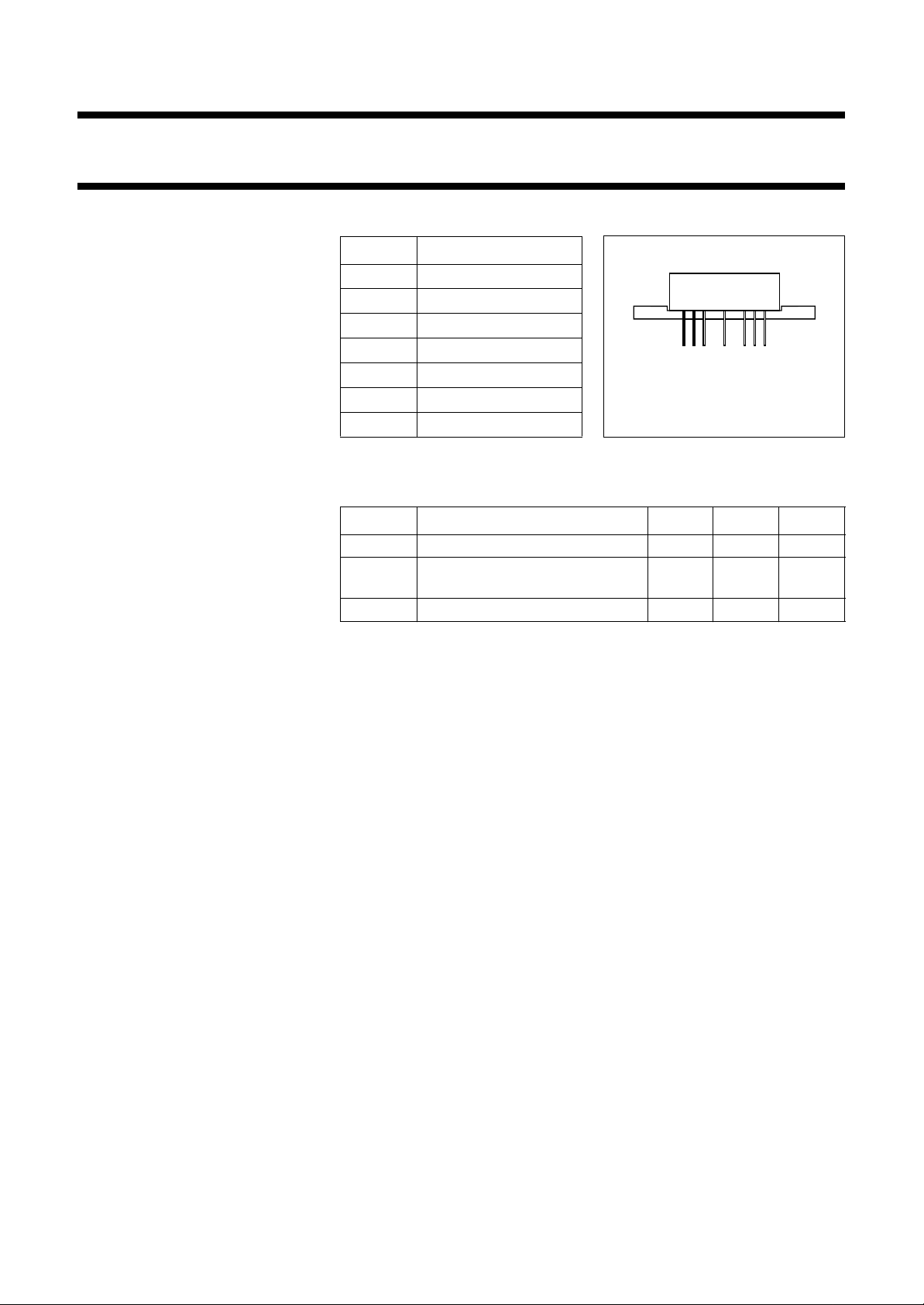
PINNING
PIN DESCRIPTION
1
2
3
5
7
8
9
input
ground
ground
supply voltage (VS)
ground
ground
output
1/3 page (Datasheet)
123 5 789
Side view
Fig.1 SOT115L.
MSB048
LIMITING VALUES
In accordance with the Absolute Maximum Rating System (IEC 134).
SYMBOL PARAMETER MIN. MAX. UNIT
V
S
T
mb
supply voltage (DC) − 70 V
operating mounting base
−20 +100 °C
temperature
T
stg
storage temperature −40 +125 °C
DESCRIPTION
Hybrid amplifier module mounted in
SOT115L package.
1995 Oct 23 2
Page 3
Philips Semiconductors Product specification
Video driver hybrid amplifier CR2424S
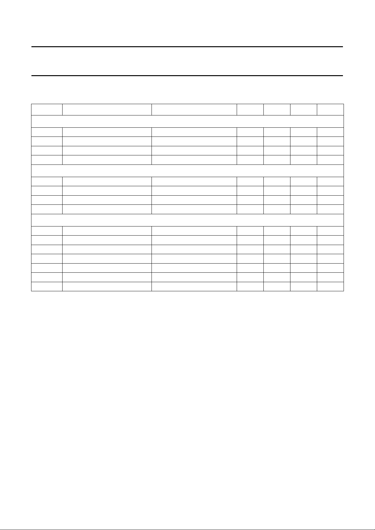
CHARACTERISTICS
T
=25°C; CL= 8.5 pF; measured in test circuit (see Fig.10); unless otherwise specified.
mb
SYMBOL PARAMETER CONDITIONS MIN. TYP. MAX. UNIT
V
= 60 V; output swing = 40 V (p-p) with 30 V (DC) offset; unless otherwise specified
S
I
S
V
I
t
r
t
f
= 65 V; output swing = 50 V (p-p) with 32.5 V (DC) offset; unless otherwise specified
V
S
I
S
V
I
t
r
t
f
= 60 or 65 V; output swing = 40 or 50 V (p-p) with 30 or 32.5 V (DC) offset; unless otherwise specified
V
S
P
tot
BW small-signal bandwidth between −3 dB points; note 3 130 145 − MHz
V
tilt
V
os
NLN non-linearity V
A
V
V
G
supply current input and output open 39 45 51 mA
input voltage (DC) input and output open 1.3 1.6 1.9 V
rise time transient response 10 to 90%; note 1 − 2.3 2.9 ns
fall time transient response 10 to 90%; note 1 − 2.1 2.6 ns
supply current input and output open − 50 57 mA
input voltage (DC) input and output open 1.4 1.75 2.1 V
rise time transient response 10 to 90%; note 2 − 2.5 3.2 ns
fall time transient response 10 to 90%; note 2 − 2.2 3.2 ns
total power dissipation 50 MHz square wave − 4.6 6 W
low frequency tilt voltage 1 kHz square wave − 1.3 1.5 V
overshoot voltage varied by C1; see Fig.10 − 310%
=5to55V − 25%
O
DC voltage gain 50 Ω source; note 4 11.2 12.4 13.2
insertion gain 50 Ω source; note 5 160 180 200
Notes
1. Input signal is a 100 kHz square wave of 3.25 V (p-p), with 1.5 V (DC) offset (50 Ω source).
2. Input signal is a 100 kHz square wave of 3.4 V (p-p), with 1.65 V (DC) offset (50 Ω source).
3. Sine wave output signal: 1 V (p-p).
4. Measured V
(Figs 2 and 6) at input test circuit (see Fig.10).
O/VI
5. Measured VO/VI (Figs 3 and 7) at input module (see Fig.10).
1995 Oct 23 3
Page 4

Philips Semiconductors Product specification
Video driver hybrid amplifier CR2424S
5
handbook, halfpage
V
I
(V)
3
1
1
0 204060
VS= 60V; Tmb=25°C; CL= 8.5 pF; output swing = 40 V (p-p)
with 30 V (DC) offset; measured in test circuit (see Fig.10).
MLC954
V (V)
O
Fig.2 Input voltage at input test circuit as a
function of output voltage; typical values.
1.9
handbook, halfpage
V
I
(V)
1.7
1.5
1.3
020
VS= 60 V; Tmb=25°C; CL= 8.5 pF; output swing = 40 V (p-p)
with 30 V (DC) offset; measured in test circuit (see Fig.10).
40 60
MLC955
VO(V)
Fig.3 Input voltage at input module as a function
of output voltage; typical values.
3.0
handbook, halfpage
t
r
(ns)
2.6
2.2
1.8
6 8 10 12 14 16
VS= 60 V; Tmb=25°C; CL= 8.5 pF;
output swing = 40, 35, 30 V (p-p) with 30 V (DC) offset;
measured in test circuit (see Fig.10).
MRA627 - 1
40 V (p-p)
35 V (p-p)
30 V (p-p)
(pF)C
L
Fig.4 Rise time transient response as a function
of load capacitance; typical values.
3.0
handbook, halfpage
t
f
(ns)
2.6
2.2
1.8
6 8 10 12 14 16
VS= 60 V; Tmb=25°C; CL= 8.5 pF;
output swing = 40, 35, 30 V (p-p) with 30 V (DC) offset;
measured in test circuit (see Fig.10).
MRA628 - 1
40 V (p-p)
35 V (p-p)
30 V (p-p)
CL(pF)
Fig.5 Fall time transient responseas a function of
load capacitance; typical values.
1995 Oct 23 4
Page 5
Philips Semiconductors Product specification
Video driver hybrid amplifier CR2424S
5
handbook, halfpage
V
I
(V)
3
1
1
0 20406080
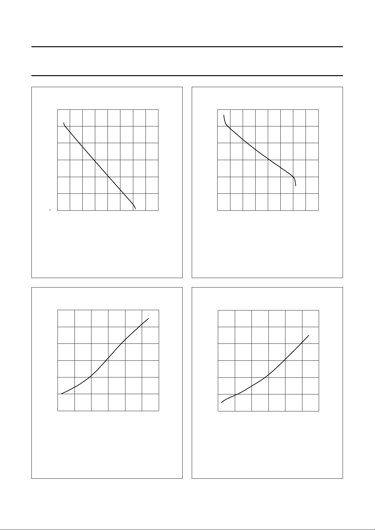
VS= 65 V; Tmb=25°C; CL= 8.5 pF; output swing = 50 V (p-p)
with 32.5 V (DC) offset; measured in test circuit (see Fig.10).
V (V)
O
Fig.6 Input voltage at input test circuit as a
function of output voltage; typical values.
MLC956
2.0
handbook, halfpage
V
I
(V)
1.8
1.6
1.4
0 20406080
VS= 65 V; Tmb=25°C; CL= 8.5 pF; output swing = 50 V (p-p)
with 32.5 V (DC) offset; measured in test circuit (see Fig.10).
MLC957
V (V)
O
Fig.7 Input voltage at input module as a function
of output voltage; typical values.
3.4
handbook, halfpage
t
r
(ns)
3.0
2.6
2.2
6 101418
VS= 65 V; Tmb=25°C; CL= 8.5 pF; output swing = 50 V (p-p)
with 32.5 V (DC) offset; measured in test circuit (see Fig.10).
MRA617 - 1
(pF)C
L
Fig.8 Rise time transient response as a function
of load capacitance; typical values.
3.2
handbook, halfpage
t
f
(ns)
2.8
2.4
2.0
6101418
VS= 65 V; Tmb=25°C; CL= 8.5 pF; output swing = 50 V (p-p)
with 32.5 V (DC) offset; measured in test circuit (see Fig.10).
MRA615 - 1
CL(pF)
Fig.9 Fall time transient responseas a function of
load capacitance; typical values.
1995 Oct 23 5
Page 6
Philips Semiconductors Product specification
Video driver hybrid amplifier CR2424S
V
handbook, full pagewidth
C2
S
PULSE
GENERATOR
input
50 Ω
C1
R1
BIAS
UNIT
5
1
CR2424S
TEST
FIXTURE
CR2424S
POWER
SUPPLY
2
3
9
8
7
output
C
L
FET
PROBE
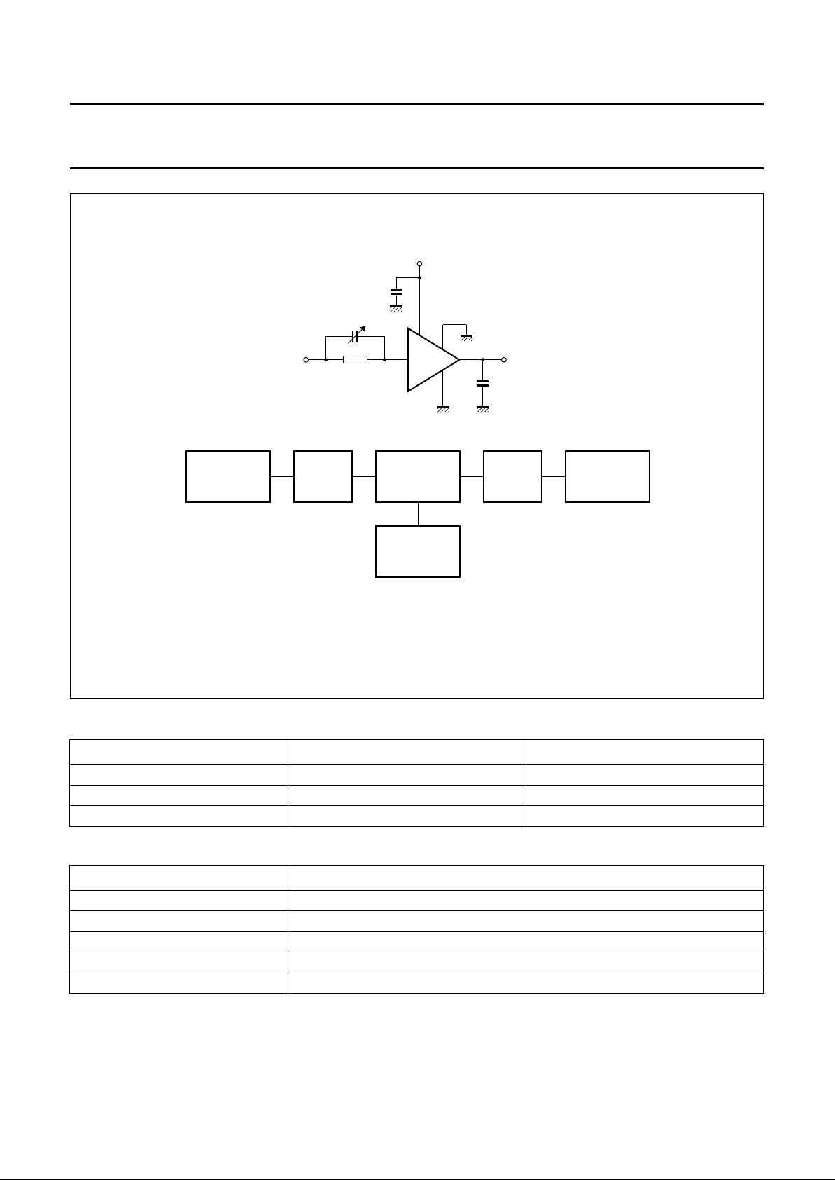
Fig.10 CRT amplifier test circuit and block diagram.
SAMPLING
OSCILLOSCOPE
MAM143
Components used in test circuit (see Fig.10)
DESIGNATION DESCRIPTION VALUE
C
1
C
2
variable capacitor 10 to 120 pF (typ. 50 pF)
chip capacitor 10 nF
R1 resistor typ. 215 Ω
Equipment used in test circuit (see Fig.10)
EQUIPMENT TYPE DESCRIPTION
Pulse generator Pico Second; Model 2600B
Bias unit Pico Second; Model 5555
Power supply Philips; Model PE1541, 80 V
FET probe Philips; Model PM8943, attenuation 100 : 1
Sampling oscilloscope Tektronix; Model 11803, sampling head SD24
1995 Oct 23 6
Page 7
Philips Semiconductors Product specification
Video driver hybrid amplifier CR2424S
handbook, full pagewidth
input
180 Ω
3.3 nF
100 V
6.4 kΩ
180 Ω
150 kΩ
22 nF
100 V
680 pF
100 V
3 kΩ
150
82
pF
47 Ω
82
pF
pF
6.8 Ω
150 pF
6.8 Ω
MLC940
22 nF
100 V
10 Ω
1 nF
10 Ω
30
Ω
30
Ω
supply
3 kΩ
output
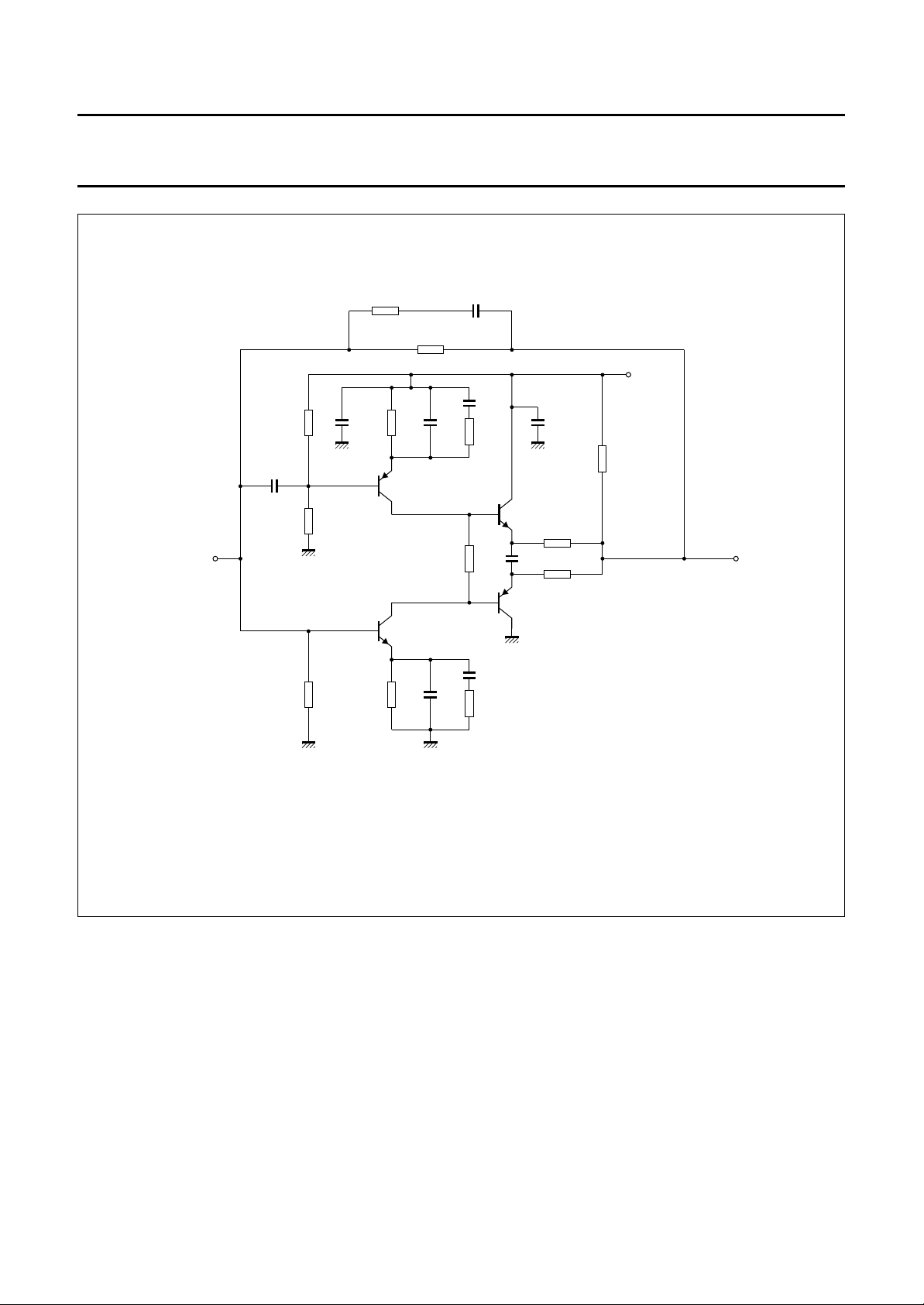
Fig.11 Internal circuit.
1995 Oct 23 7
Page 8

Philips Semiconductors Product specification
Video driver hybrid amplifier CR2424S
PACKAGE OUTLINE
handbook, full pagewidth
9.2
max
44.8
max
8.8
min
0.25
2.54
38.1
13.8 max
8
2.4 max
4.15
3.85
3.15
27.2 max
3.8 max
123578
0.51
2.54
0.38
(5.08)
11.5
max
9
M
O0.25
MSA240 - 1
Dimensions in mm.
Heatsink compound must be applied sparingly and evenly distributed.
Fig.12 SOT115L.
1995 Oct 23 8
Page 9

Philips Semiconductors Product specification
Video driver hybrid amplifier CR2424S
DEFINITIONS
Data sheet status
Objective specification This data sheet contains target or goal specifications for product development.
Preliminary specification This data sheet contains preliminary data; supplementary data may be published later.
Product specification This data sheet contains final product specifications.
Limiting values
Limiting values given are in accordance with the Absolute Maximum Rating System (IEC 134). Stress above one or
more of the limiting values may cause permanent damage to the device. These are stress ratings only and operation
of the device at these or at any other conditions above those given in the Characteristics sections of the specification
is not implied. Exposure to limiting values for extended periods may affect device reliability.
Application information
Where application information is given, it is advisory and does not form part of the specification.
LIFE SUPPORT APPLICATIONS
These products are not designed for use in life support appliances, devices, or systems where malfunction of these
products can reasonably be expected to result in personal injury. Philips customers using or selling these products for
use in such applications do so at their own risk and agree to fully indemnify Philips for any damages resulting from such
improper use or sale.
1995 Oct 23 9
 Loading...