

Page 1

LHD700
SERVICE MANUAL
020-000423-02
Page 2

Page 3
FILE NO.
SERVICE MANUAL
Multimedia Projector
Model No. LHD700
U.S.A, Canada,
Europe
Original Version
* Projection lens is optional.
PRODUCT CODE
1 122 571 29
(KY2KL)
Match the Chassis No. on the rating label of the projector
with the Chassis No. in the Service Manual.
If the Original Version Service Manual Chassis No. does
not match the projector’s, additional Service Literature is
required. You must refer to “Notices” to the Original Service Manual prior to servicing.
LHD700 Service Manual
020-000423-02 Rev.1 (01-2013)
Chassis No. 103-034108-01-00
REFERENCE NO. SM5111373-00
Page 4

Contents
SERVICE MANUAL ....................................................... 1
Contents ........................................................................ 2
Safety Instructions ......................................................... 3
Safety Precautions ..................................................... 3
Product Safety Notice ................................................. 3
Service Personnel Warning ........................................ 3
Specifications ................................................................ 4
Circuit Protections .........................................................5
Fuse ............................................................................ 5
Thermal protector (SW905) ........................................ 5
Mechanical sensor switches (SW1891,SW1861) ........6
Temperature sensors, wind sensors .......................... 7
Power failure and fan lock detection .......................... 8
Maintenance .................................................................. 9
Replacing the filter cartridge ...................................... 9
Resetting the filter counter ....................................... 10
Resetting the scroll counter ...................................... 10
Lamp Replacement .................................................. 11
Resetting the lamp counter ...................................... 12
How to check lamp used time .................................. 12
Cleaning ................................................................... 13
Quick maintenance ................................................... 14
Security Function Notice ............................................. 15
Mechanical Disassembly............................................. 16
Mechanical disassembly flow chart .......................... 16
Mechanical disassembly .......................................... 17
Optical Parts Disassembly .......................................... 29
Adjustments ................................................................. 39
Adjustments after parts replacement ....................... 39
Note on main board replacement ............................. 39
Optical Adjustments .................................................... 40
Contrast adjustment ................................................. 40
Electrical Adjustments ................................................. 41
Service Adjustment Menu Operation ....................... 41
Memory IC (IC1387) Replacement ........................... 41
Circuit Adjustments .................................................. 42
Test Points and Locations ........................................ 46
Service Adjustment Data Table ................................ 47
Chassis Description .................................................... 72
Chassis over view ..................................................... 72
Input & signal processing stage ...............................73
LCD drive stage ........................................................ 74
Lamp control stage ................................................... 75
Fan control stage ...................................................... 76
Motor control stage ................................................... 77
Bus control stage ...................................................... 78
LED drive & RC control stage ................................... 79
Power supply & power failure circuit ......................... 80
Indicators and Projector Condition ........................... 81
Power failure detection system ................................ 84
Error information table .............................................. 84
Power failure detection tree ...................................... 85
Error History Log ...................................................... 87
Diagnosis of Power Failure with RS-232C port ........ 88
Diagnosis procedure ................................................88
Serial Control Interface ............................................. 89
Control Port Functions................................................. 91
System Control I/O Port Functions (PW392, IC301) 91
I/O Expander (TE7783, IC4801) .............................. 92
FPGA (XC3S50A, IC5201) ....................................... 93
IIC Bus D/A Converter (M62393FP Fan Control,
IC7801) ..................................................................... 93
IC Block Diagrams....................................................... 94
Mechanical Parts List ................................................ 101
Cabinet Parts Location ........................................... 101
Mechanical Parts List ............................................. 108
Electrical Parts List .....................................................110
Electrical Parts Location .......................................... 111
Electrical Parts List ..................................................112
Diagrams & Drawings .................................................. A1
Parts description and reading in schematic diagram ..A2
Pin description of diode, transistor and IC ................ A17
Note on Soldering ...................................................... A18
Schematic Diagrams ...................................................A3
Printed Wiring Board Drawings ................................. A13
-2-
LHD700 Service Manual
020-000423-02 Rev.1 (01-2013)
Page 5

Safety Instructions
Safety Precautions
WARNING:
The chassis of this projector is isolated (COLD) from AC line by using the converter transformer. Primary side
of the converter and lamp power supply unit circuit is connected to the AC line and it is hot, which hot circuit is
identified with the line ( ) in the schematic diagram. For continued product safety and protection of personnel injury, servicing should be made with qualified personnel.
The following precautions must be observed.
ment covers or shields, barriers, etc.
1: An isolation transformer should be connected in
the power line between the projector and the AC
line before any service is performed on the projector.
DO NOT OPERATE THIS PROJECTOR WITHOUT
THE PROTECTIVE SHIELD IN POSITION AND PR
OPERLY SECURED.
2: Comply with all caution and safety-related notes
provided on the cabinet back, cabinet bottom, inside
the cabinet or on the chassis.
3: When replacing a chassis in the cabinet, always
be certain that all the protective devices are
installed properly, such as, control knobs, adjust-
4: Before replacing the cabinet cover, thoroughly
inspect the inside of the cabinet to see that no stray
parts or tools have been left inside.
Before returning any projector to the customer, the
service personnel must be sure it is completely safe
to operate without danger of electric shock.
Product Safety Notice
Product safety should be considered when a component replacement is made in any area of the projector.
Components indicated by mark ! in the parts list and the schematic diagram designate components in which
safety can be of special significance. It is, therefore, particularly recommended that the replacement of there
parts must be made by exactly the same parts.
Service Personnel Warning
Eye damage may result from directly viewing the light produced by the Lamp used in this equipment. Always
turn off Lamp before opening cover. The Ultraviolet radiation eye protection required during this servicing.
Never turn the power on without the lamp to avoid electric-shock or damage of the devices since the stabilizer
generates high voltages (15kV - 25kV) at its starts.
Since the lamp is very high temperature during units operation replacement of the lamp should be done at least
45 minutes after the power has been turned off, to allow the lamp cool-off.
LHD700 Service Manual
020-000423-02 Rev.1 (01-2013)
-3-
Page 6

Specifications
Mechanical Information
Projector Type Multi-media Projector
Dimensions (W x H x D) 14.56” x 7.36” x 17.32” (370.0 mm x 187.0 mm x 439.9 mm)
Net Weight 25.6 lbs (11.6 kg)
Feet Adjustment 0˚ to 6.5˚
Panel Resolution
LCD Panel System 1.2” TFT Active Matrix type, 3 panels
Panel Resolution 1,920 x 1080 dots
Number of Pixels 6,220,800 (1,920 x 1080 x 3 panels)
Signal Compatibility
Color System
High Definition TV Signal 480i, 480p, 575i, 575p, 720p, 1035i, 1080i and 1080p
Scanning Frequency H-sync. 15 kHz–120 kHz, V-sync. 48 Hz–100 Hz
Optical Information
Projection Lamp 380 W lamp
Interface
Input 1 DVI [RGB(PC digital), RGB(AV HDCP)] / HDMI (1.3 with Deepcolor) / Mini D-sub 15pin [RGB,
Input 2 BNC Type x 5 (G or Video/Y, B or Cb-Pb, R or Cr-Pr, H/HV and V)
Input 3 RCA Type x 3 (Video/Y, Pb/Cb, Pr/Cr), Mini DIN 4 pin x 1 (S-video)
Monitor Out
R/C Jack Mini jack (Wired Remote) x 1
Control Port D-sub 9 pin x 1
USB Connector USB Series B x 1
Option Network box Terminal x 1
LAN Connection Terminal RJ-45
Analog RGB (Mini D-sub 15 pin) Terminal x 1
Power
Voltage and Power Consumption AC 100–120 V (5.9A Max.), 50/60 Hz (The U.S.A and Canada)
AC 100–240 V (5.9A-2.4A Max.), 50/60 Hz (For other countries)
Operating Environment
Operating Temperature 41˚F–104˚F (5˚C–40˚C)
Storage Temperature 14˚F–140˚F (-10˚C–60˚C)
Remote Control
Battery AAA or LR03 Type x 2
Operating Range 16.4’ (5 m/±30˚)
Dimensions 1.9” (W) x 1.1” (H) x 5.7” (D) (48 mm x 27 mm x 145 mm)
Net Weight 3.6 oz (102 g) (including batteries)
Accessories
Owner’s Manual (CD-ROM) Lens Attachment (For option lens)
Quick Reference Guide Light-block sheet (For option lens)
AC Power Cord Spacer (For option lens)
Remote Control and Batteries VGA Cable
PIN Code Label
PAL, SECAM, NTSC, NTSC4.43, PAL-M, and PAL-N
RGB (Scart)]
● The specifications are subject to change without notice.
● LCD panels are manufactured to the highest possible standards. Even though 99.99% of the pixels are effective, a tiny
fraction of the pixels (0.01% or
less) may be ineffective by the characteristics of the LCD panels.
This symbol on the nameplate means the product is Listed by Underwriters
Laboratories Inc. It is designed and manufactured to meet rigid U.L. safety standards against risk of fire, casualty and electrical hazards.
-4-
LHD700 Service Manual
020-000423-02 Rev.1 (01-2013)
Page 7
Circuit Protections
This projector provides the following circuit protections to operate in safety. If the abnormality occurs inside the projector, it will automatically turn off by operating one of the following protection circuits.
Fuse
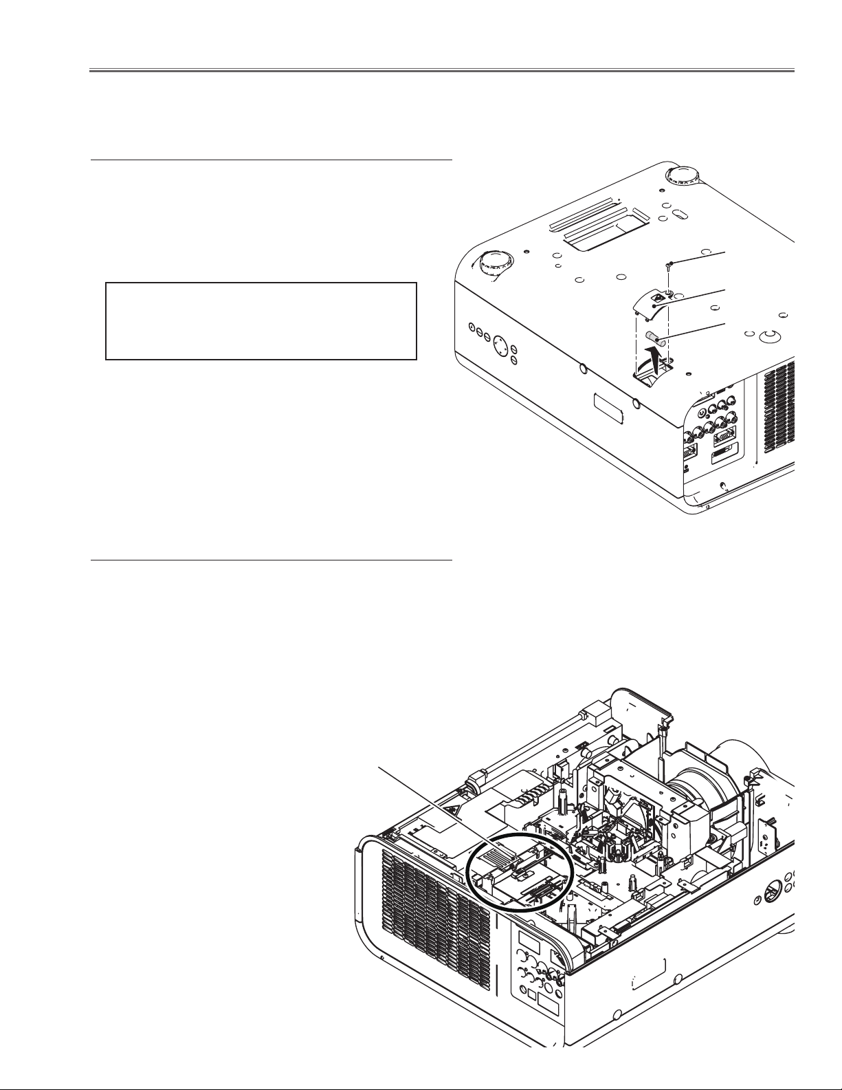
A fuse is located inside of the projector. When the POWER
indicator is not lightning, the fuse may be opened. Check
the fuse as following steps.
The fuse should be used with the following type;
Screw
Fuse Part No. : 323 027 2605
TYPE T10AH 250V
LITTEL FUSE INC. TYPE 215010
How to replace the fuse
1. Turn the projector up and down.
2. Remove 1 screw and take the fuse cover off.
3. Remove the fuse from fuse holder on the power board.
To install the fuse, take reversed step in the above.
Thermal protector (SW905)
There is the thermal protector (SW905) inside of the projector to detect the internal temperature rising abnormally.
When the internal temperature reaches near 115˚C, the thermal protector cuts off the current supplied to the power supply circuit.
To reset the thermostat, disconnect the AC cord and leave
the projector at the normal surrounding temperature for
about 45 minutes. The thermostat will automatically reset
when the internal temperature becomes less than 75˚C.
Fuse cover
Fuse
LHD700 Service Manual
020-000423-02 Rev.1 (01-2013)
Thermal protector
(SW905)
-5-
Page 8
Circuit Protections
Mechanical sensor switches (SW1891,SW1861)
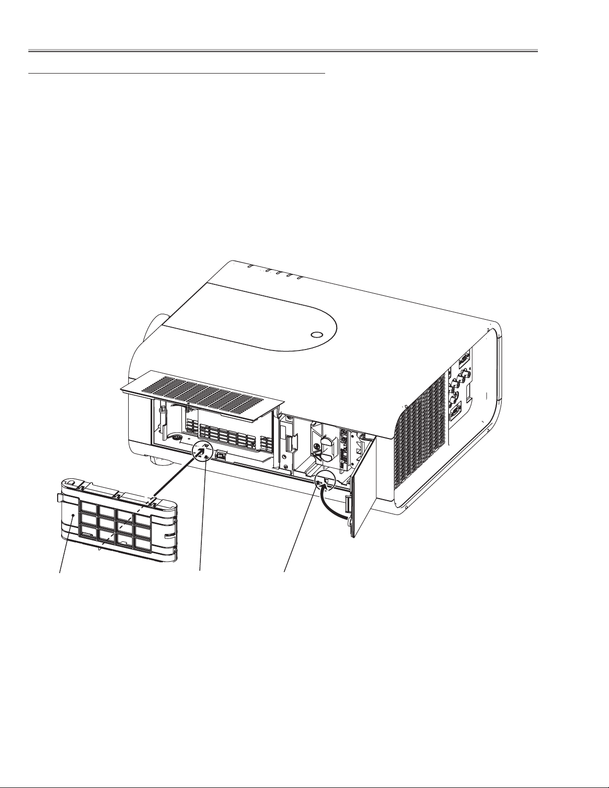
This projector provides 2 mechanical sensor switches, the one is for
filter cartridge sensor switch (SW1891) and the other one is for lamp
cover sensor switch (SW1861). The filter cartridge sensor switch
detects whether the filter cartridge is installed correctly. If the filter
cartridge is not installed correctly, the projector cannot turn on.
The lamp cover sensor switch detects whether the lamp cover is
closed securely. If lamp cover is opened or not closed completely,
the drive signal to the lamp circuit is cut off. After opening the lamp
cover for replacing the lamp ass’y, place the lamp cover correctly
otherwise the projector cannot turn on.
Filter cartridge
Filter cartridge sensor
switch (SW1891)
Lamp cover sensor
switch (SW1861)
-6-
LHD700 Service Manual
020-000423-02 Rev.1 (01-2013)
Page 9
Circuit Protections
Temperature sensors, wind sensors
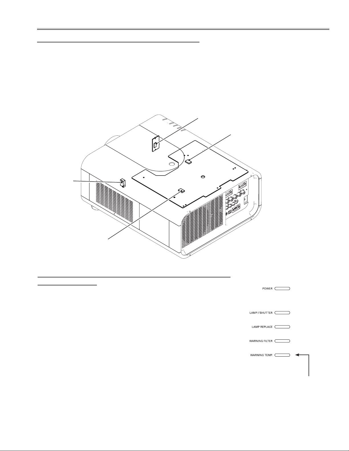
The projector provides 3 temperature sensor ICs, 2 sensors on the Main board and 1 sensor on the RC front board,
and 1 wind sensor on the intake duct. The sensor ICs monitor surrounding temperature of the lamp house and panels/prism, and room temperature, and the wind sensor monitors airflow passed through the air filter in the intake
duct.
- Internal temperature sensor B (IC1816) (around the lamp house)
- Internal temperature sensor C (IC1814) (around the panels/prism)
- Room temperature sensor A (IC1692) (around the front cabinet)
- Wind sensor D (S901) (intake duct)
IC1692
IC1814
(Behind)
S901
IC1816
(Behind)
The projector is shut down and the WARNING TEMP. indicator is blinking red.
When the temperature inside the projector reaches a certain level, the WARNING TEMP. indicator starts blinking. If the temperature rises moreover, the
projector will be automatically shut down to protect the inside of the projector,
and the WARNING TEMP. indicator is blinking fast and the POWER indicator
turns off. When the projector has cooled down enough (to its normal operating temperature), the POWER indicator turns on and the projector can be
turned on again by pressing the ON/STAND-BY button.
✔Note:
• The WARNING TEMP. indicator continues to blink even after the temperature inside the projector returns to normal. When the projector is turned on
again, the WARNING TEMP. indicator stops blinking.
Check the items below
- Remove dust around the air filter.
- Ventilation slo
projector so that ventilation slots are not obstructed.
- Check if projector is used at higher temperature place (Norma; operating
temperature is 5 to 40 ºC or 41 to 104 ºF).
ts of the projector are blocked. In such an event, reposition the
LED indicators
WARNING TEMP.
blinking red
LHD700 Service Manual
020-000423-02 Rev.1 (01-2013)
-7-
Page 10
Circuit Protections
Power failure and fan lock detection
The projector provides the detection circuits of the power failure and the fan lock. When the detection circuit detects
an error at the power supply line or at the fan operation circuit, the projector will turn into the standby mode to protect
the other circuits defective.
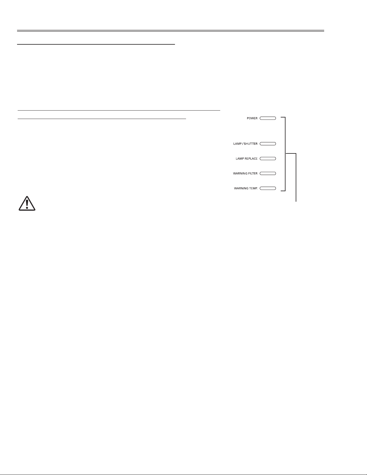
The projector is shut down; and the LAMP/SHUTTER indicator is lighting and other indicators are blinking.
When the projector detects an abnormal condition (Power supply lines failure
or fans failure), it will be automatically shut down to protect the inside of the
projector and the LAMP/SHUTTER indicator lights on and other indicators
blink. In this case, unplug the AC power cord and plug it, and then turn on the
projector once again to verify operation. If the projector cannot be turned on
and these indicators are still lighting and blinking, unplug the AC power cord.
See the troubleshooting chapter.
CAUTION
DO NOT LEAVE THE PROJECTOR WITH THE AC POWER CORD
CONNECTED UNDER AN ABNORMAL CONDITION. IT MAY RESULT IN FIRE OR ELECTRIC SHOCK.
LED indicators
LAMP/SHUTTER indicator lights on and other
four indicators blink
-8-
LHD700 Service Manual
020-000423-02 Rev.1 (01-2013)
Page 11
Maintenance
Replacing the filter cartridge
Filter prevents dust from accumulating on the optical elements inside the projector. Should the filter becomes clogged
with dust particles, it will reduce cooling fans’ effectiveness and may result in internal heat buildup and adversely
affect the life of the projector. This projector has an electrically operated filter which helps you to replace the filter
easily. The projector monitors the condition of the filter at all time and replaces a filter with a new one automatically
when it detects the clogging.
If the projector detects that the filter is clogged and no scroll is left in the filter cartridge, a Filter cartridge replacement
icon appears on the screen and the WARNING FILTER indicator on the top panel lights up. When you see this icon,
replace the filter cartridge and reset the Filter counter and the Scroll counter.
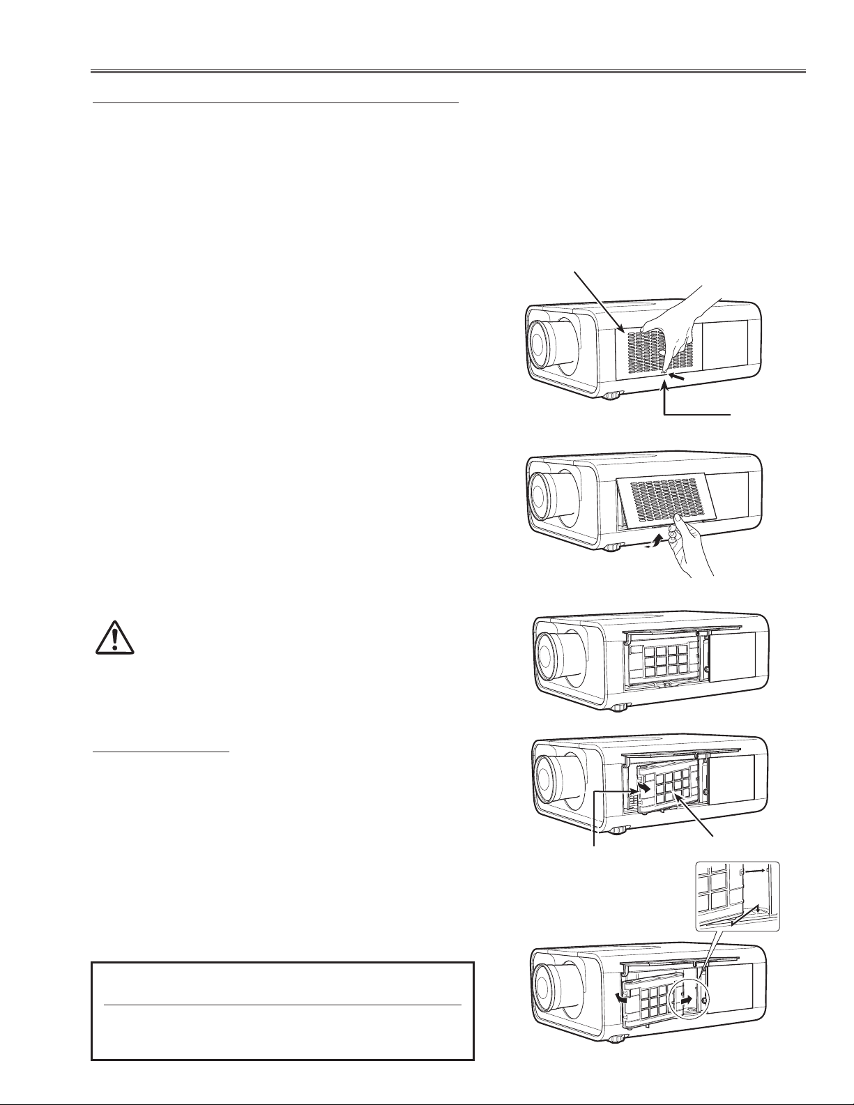
Filter cover
Turn off the projector, and unplug the AC power cord
1
from the AC outlet.
First, clean up the dust on the projector and around the
2
air vents.
Press d on the filter cover to release the latch and open
3
the filter cover.
Pull out the filter cartridge. When taking out the filter
4
cartridge, put your finger on the filter cartridge’s tab and
then pull.
Put the new one back into the position and close the
5
filter cover. Make sure that the filter cartridge is properly
and fully inserted.
Connect the AC power cord to the projector and turn
6
on the projector.
Reset the filter counter and the scroll counter.
7
CAUTION
Do not operate the projector with the filter removed.
Dust may accumulate on the optical elements degrading the picture quality.
Do not put anything into the air vents. Doing so may
result in malfunction of the projector.
RECOMMENDATION
We recommend avoiding dusty/smoky environments
when operating the projector. Usage in these environments may cause a poor image quality.
Latch
When using the projector under dusty or smoky conditions,
dust may accumulate on a lens, liquid crystal panels, or optical elements inside the projector. Such condition may degrade the quality of the projected image.
When the symptoms above are noticed, contact your authorized dealer or service station for proper cleaning.
ORDER REPLACEMENT FILTER CARTRIDGE
Type No. 003-003965-01
LHD700 Service Manual
020-000423-02 Rev.1 (01-2013)
-9-
Tab
Filter cartridge
Page 12
Resetting the filter counter
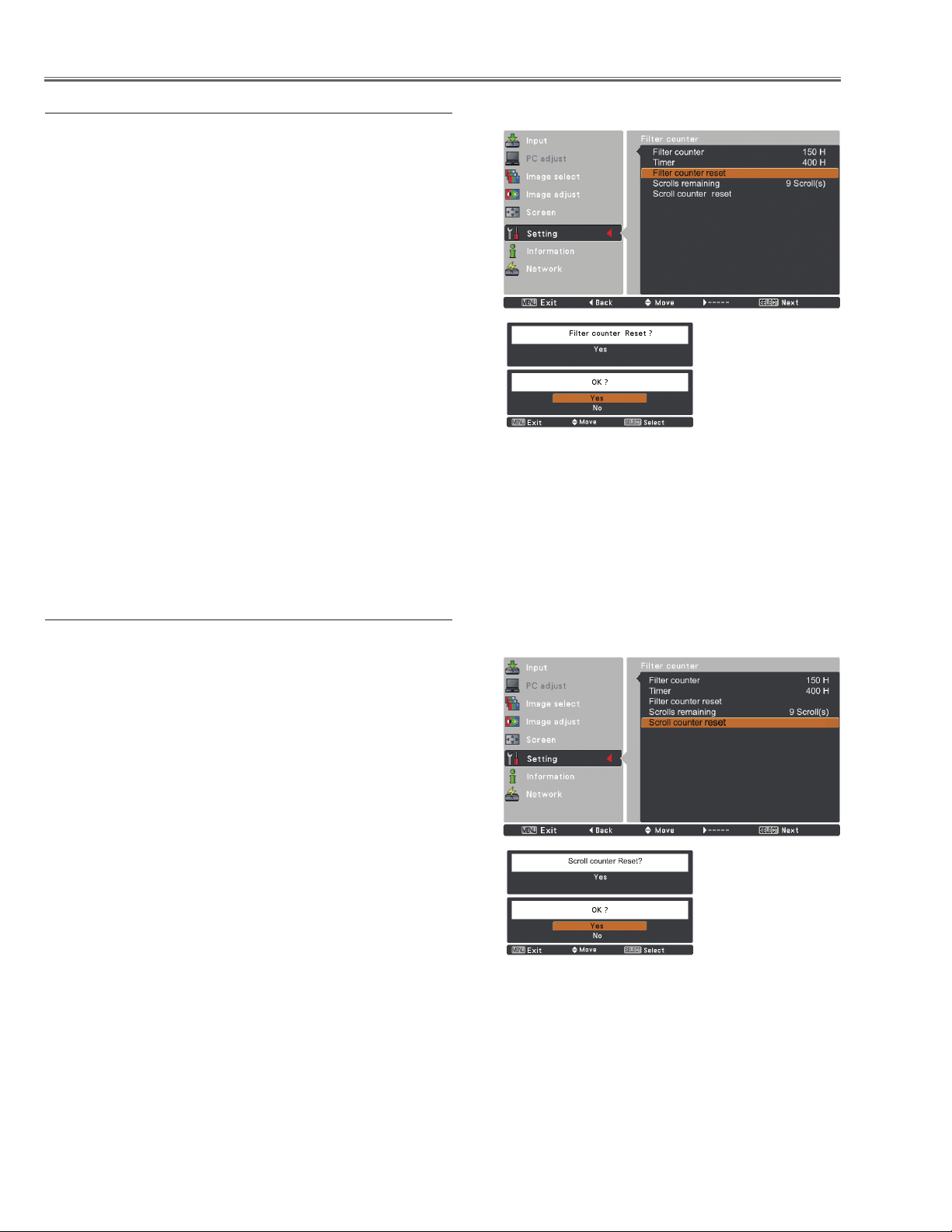
Be sure to reset the filter counter after replacing the filter and
the filter cartridge.
Press the MENU button to display the on-screen menu.
1
Use the point ed buttons to select Setting and then
press the point 8 button or the SELECT button.
Use the point ed buttons to select the Filter coun-
2
ter and then press the SELECT button. Use the Point
ed buttons to select the Filter counter reset and then
press the SELECT button. Filter counter Reset? appears. Select Yes to continue.
Another confirmation dialog box appears, select Yes to
3
reset the filter counter.
Filter counter
Filter counter Reset? appears.
Select [Yes], then another confirmation box appears.
Select [Yes] again to reset the Filter counter.
Resetting the scroll counter
Be sure to reset the scroll counter after replacing the filter
cartridge.
Press the MENU button to display the on-screen menu.
1
Use the point ed buttons to select Setting and then
press the point 8 button or the SELECT button.
Use the point ed buttons to select the Scroll counter
2
and then press the SELECT button. Use the Point ed
buttons to select the Scroll counter reset and then
press the SELECT button. Scroll counter Reset? appears. Select Yes to continue.
Another confirmation dialog box appears, select Yes to
3
reset the scroll counter.
Scroll counter
Scroll counter Reset? appears.
Select [Yes], then another confirmation box appears.
Select [Yes] again to reset the Scroll counter.
-10-
LHD700 Service Manual
020-000423-02 Rev.1 (01-2013)
Page 13
Maintenance
Lamp Replacement
When the projection lamp of the projector reaches its end of life, the lamp replacement icon appears on the screen
and LAMP REPLACE indicator lights orange. Replace the lamp with a new one promptly. The timing when the LAMP
REPLACE indicator should light is depending on the lamp mode.
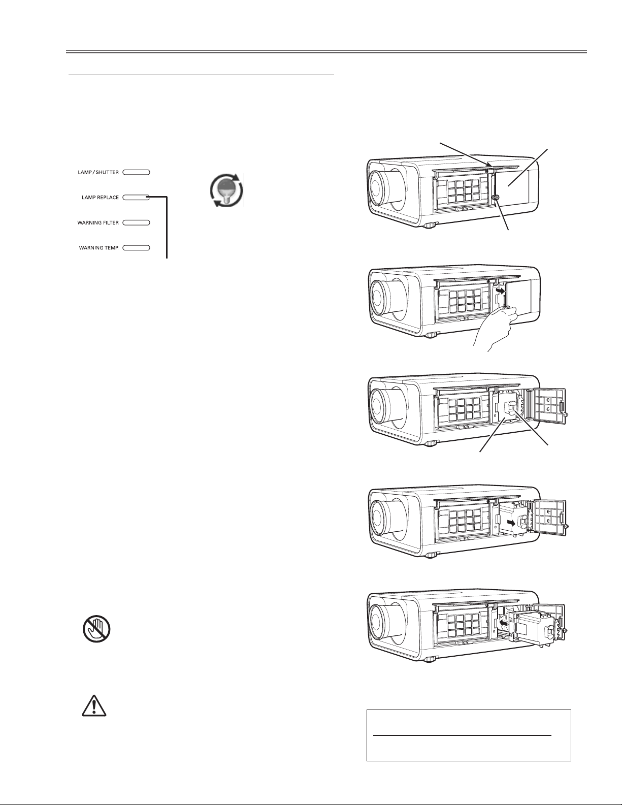
Top Panel
Lamp replacement icon
LAMP REPLACE indicator
Follow these steps to replace the lamp.
Turn off the projector and unplug the AC power cord.
1
Let the projector to cool for at least 45 minutes.
Open the filter cover.
2
Filter cover
Lamp cover
Screw
Loosen the screw and open the lamp cover and pull
3
out the lamp by using the built in handle.
Replace the lamp with a new one. Make sure that
4
the lamp is properly and fully inserted.
Close the lamp cover and secure the screw, and
5
close the filter cover.
Connect the AC power cord to the projector and turn
6
on the projector.
Reset the lamp replacement counter
7
Note:
• Be sure to insert the lamp in the correct direction.
• Do not reset the Lamp replacement counter when the projection lamp is not replaced.
CAUTION
Allow a projector to cool for at least 45 minutes
before you open the lamp cover. The inside of the
projector can become very hot.
Lamp
Handle
CAUTION
For continued safety, replace with a lamp of the
same type. Do not drop the lamp or touch the glass
bulb! The glass can shatter and may cause injury.
LHD700 Service Manual
020-000423-02 Rev.1 (01-2013)
ORDER REPLACEMENT LAMP
Type No. 003-120641-01
-11-
Page 14
Counter
Projector 500 H
Lamp
Normal 200 H
Eco 300 H
Corresponding value 600 H
Maintenance
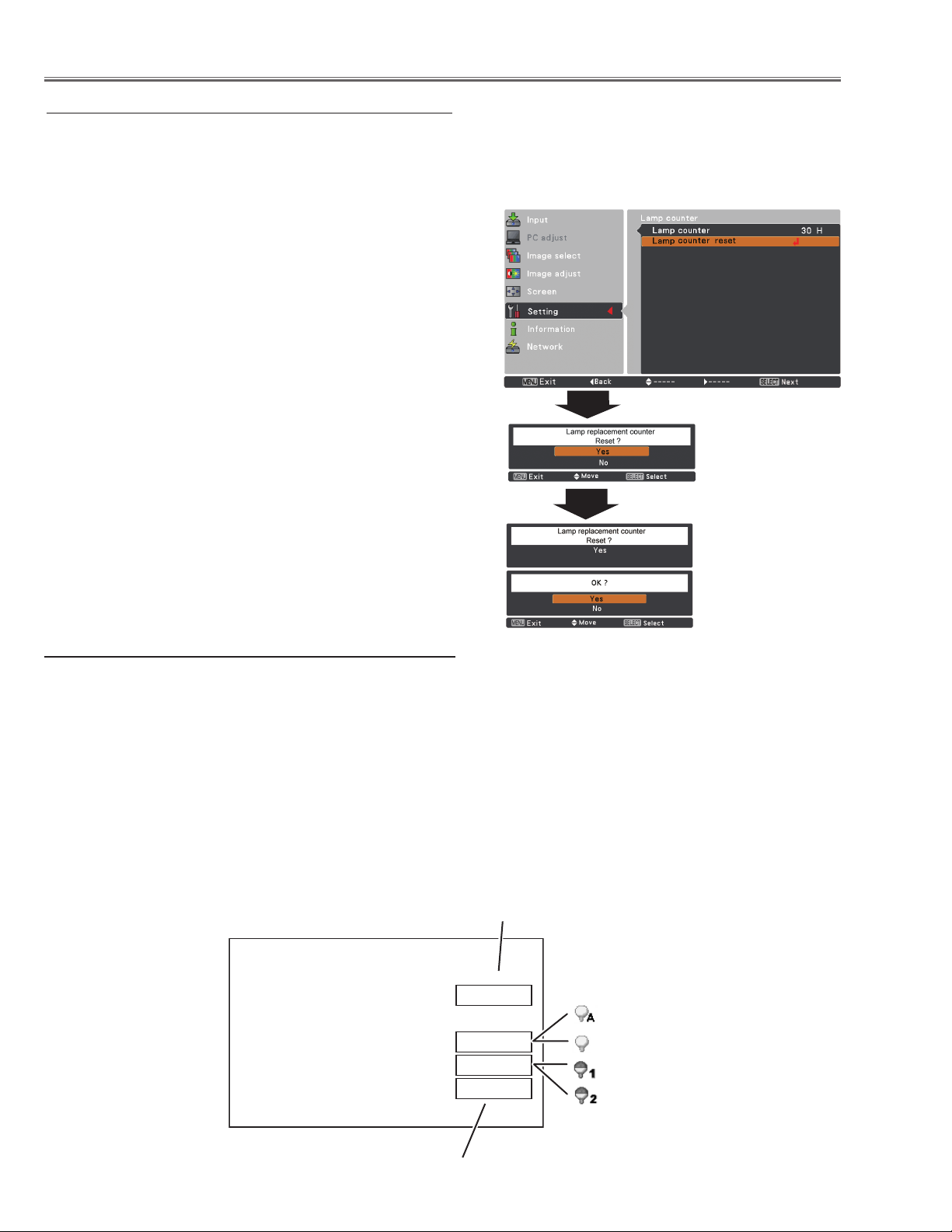
Resetting the lamp counter
Be sure to reset the lamp counter after the lamp is replaced. When the lamp counter is reset, the LAMP REPLACE indicator stops lighting and the lamp replacement icon disappears.
Press the MENU button to display the on-screen menu.
1
Use the point ed buttons to select Setting and then
press the point 8 button or the SELECT button.
Use the point ed buttons to select the Lamp coun-
2
ter and then press the SELECT button. Use the Point
ed buttons to select the Lamp counter reset and then
press the SELECT button. Lamp replacement coun-
ter Reset? appears. Select Yes to continue.
Another confirmation dialog box appears, select Yes to
3
reset the lamp counter.
Note:
• Do not reset the lamp counter without replacing the lamp. Be
sure to reset the lamp replacement counter only after replacing
the lamp.
Lamp counter
How to check lamp used time
The LAMP REPLACE indicator will light yellow when the total lamp used time (Corresponding value) reaches 3,000
hours. This is to indicate that lamp replacement is required.
The total lamp used time is calculated by using the below expression,
Total lamp used time (Corresponding value) = Teco + (Tnormal x 1.5)
Teco: used time in the Eco1 and Eco2 mode
Tnormal : used time in the normal mode and auto mode
You can check the lamp used time following to the below procedure.
1 Press and hold the ON/STAND-BY button on the projector or the ON button on the remote control for more than
20 seconds.
2 The projector used time and lamp used time will be displayed on the screen briefly as follows.
Projector used time
Lamp mode
Total lamp used time
-12-
LHD700 Service Manual
020-000423-02 Rev.1 (01-2013)
Page 15

Maintenance
Cleaning
After long periods of use, dust and other particles will accumulate on the LCD panel, prism, mirror, polarized glass,
lens, etc., causing the picture to darken or color to blur. If this occurs, clean the inside of optical unit.
Remove dust and other particles using air spray. If dirt cannot be removed by air spray, disassemble and clean the
optical unit.
Cleaning with air spray
1. Remove the cabinet top following to “Mechanical Disassembly”.
2. Clean up the LCD panel and polarizing plate by using
the air spray from the cabinet top opening.
Caution:
Use a commercial (inert gas) air spray designed for
cleaning camera and computer equipment. Use a resinbased nozzle only. Be vary careful not to damage optical
parts with the nozzle tip. Never use any kind of cleanser
on the unit. Also, never use abrasive materials on the
unit as this may cause irreparable damage.
Disassembly Cleaning
Disassembly cleaning method should only be performed
when the unit is considerable dirty and cannot be sufficiently cleaned by air spraying alone.
Be sure to readjust the optical system after performing disassembly cleaning.
1. Remove the cabinet top and main units following to
“Mechanical Disassembly”.
2. Remove the optical base top following to “Optical
Unit Disassembly”. If the LCD panel needs cleaning,
remove the LCD panel unit following to “LCD panel
replacement”.
3. Clean the optical parts with a soft cloth. Clean extremely dirty areas using a cloth moistened with alcohol.
Caution:
The surface of the optical components consists of multiple dielectric layers with varying degrees of refraction.
Never use organic solvents (thinner, etc.) or any kind of
cleanser on these components.
Since the LCD panel is equipped with an electronic circuit, never use any liquids (water, etc.) to clean the unit.
Use of liquid may cause the unit to malfunction.
LHD700 Service Manual
020-000423-02 Rev.1 (01-2013)
-13-
Page 16
Maintenance
Quick maintenance
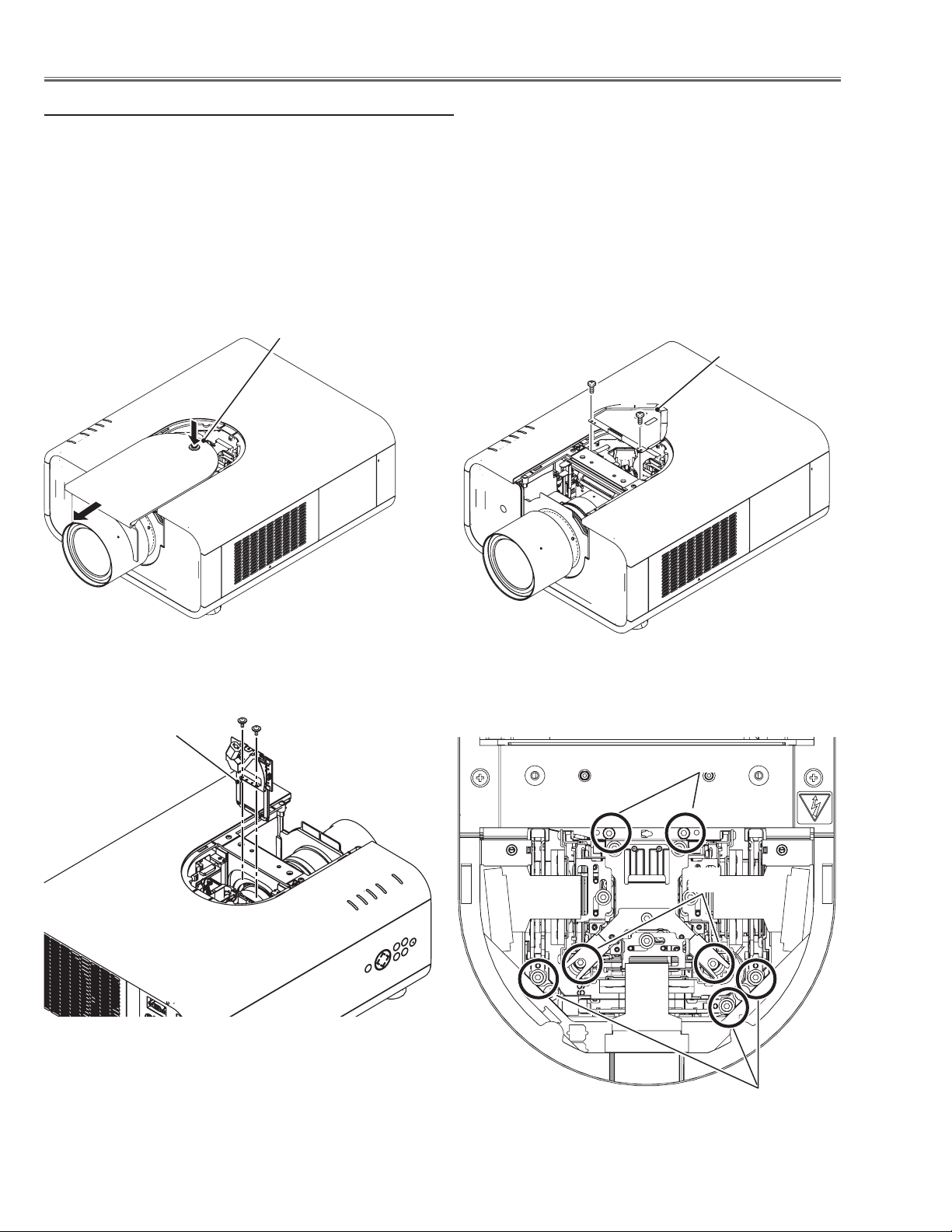
This projector provides a cabinet front cover on the cabinet top to enhance the service maintenance. This enables
service personnel to align the optical adjustment or replace the optical parts without disassembly the cabinet top.
1. Press and hold the release button on the cabinet front cover and slide the cover frontward to take it off (Fig. 1).
2. Remove 2 screws A on the prism shield cover and take prism shield cover off (Fig. 2).
3. Remove 2 screws B and take the shutter assembly off (Fig. 3).
4. Loosen 4 screws C and take the LCD Panel/Prism assy upward off.
5. Remove 1 screw D on each stopper of the polarized glass assy and take the optical filter assy upward off.
See chapter "Optical Parts Disassembly" for further information of optical parts disassembly.
Release button
Prism shield cover
A
A
Shutter assembly
Fig. 1 Fig. 2
B
B
C
C
Fig. 3
-14-
D
Fig. 4
LHD700 Service Manual
020-000423-02 Rev.1 (01-2013)
Page 17

Security Function Notice
This projector provides security functions such as "Key lock", "PIN code lock" and "Logo PIN code lock". When the
projector has set these security function on, you are required to enter correct PIN code to use the projector. If you
do not know the correct PIN code to the projector, the projector can no longer be operated or started. In this case,
you must reset those function first according to the resetting procedure described below and then check up on the
projector.
Function Description
Locks operation of the side control or the remote control.
Key lock
PIN code lock
Logo PIN code lock
If the Key lock is enabled with side control lock, the
projector can no longer be started.
Initial setting: Key lock function is disabled
Prevents the projector from being operated by an unauthorized person.
Initial code: “1234”
Prevents an unauthorized person for changing the
start-up logo on the screen.
Initial code: “4321”
Resetting procedure
1 Disconnect the AC power cord from the AC outlet.
2 As pressing the SELECT button, connect the AC power cord into an AC outlet again.
3 Keep pressing the SELECT button and then press the ON /STAND-BY button for more than 5 seconds.
4 Release the ON/STAND-BY button first and then release the SELECT button.
- The PIN code lock and Logo PIN code lock will be reset as the initial PIN code at the factory and the Key
lock function is disabled.
Please refer to the owner's manual for further information of the security functions.
LHD700 Service Manual
020-000423-02 Rev.1 (01-2013)
-15-
Page 18
Mechanical Disassembly
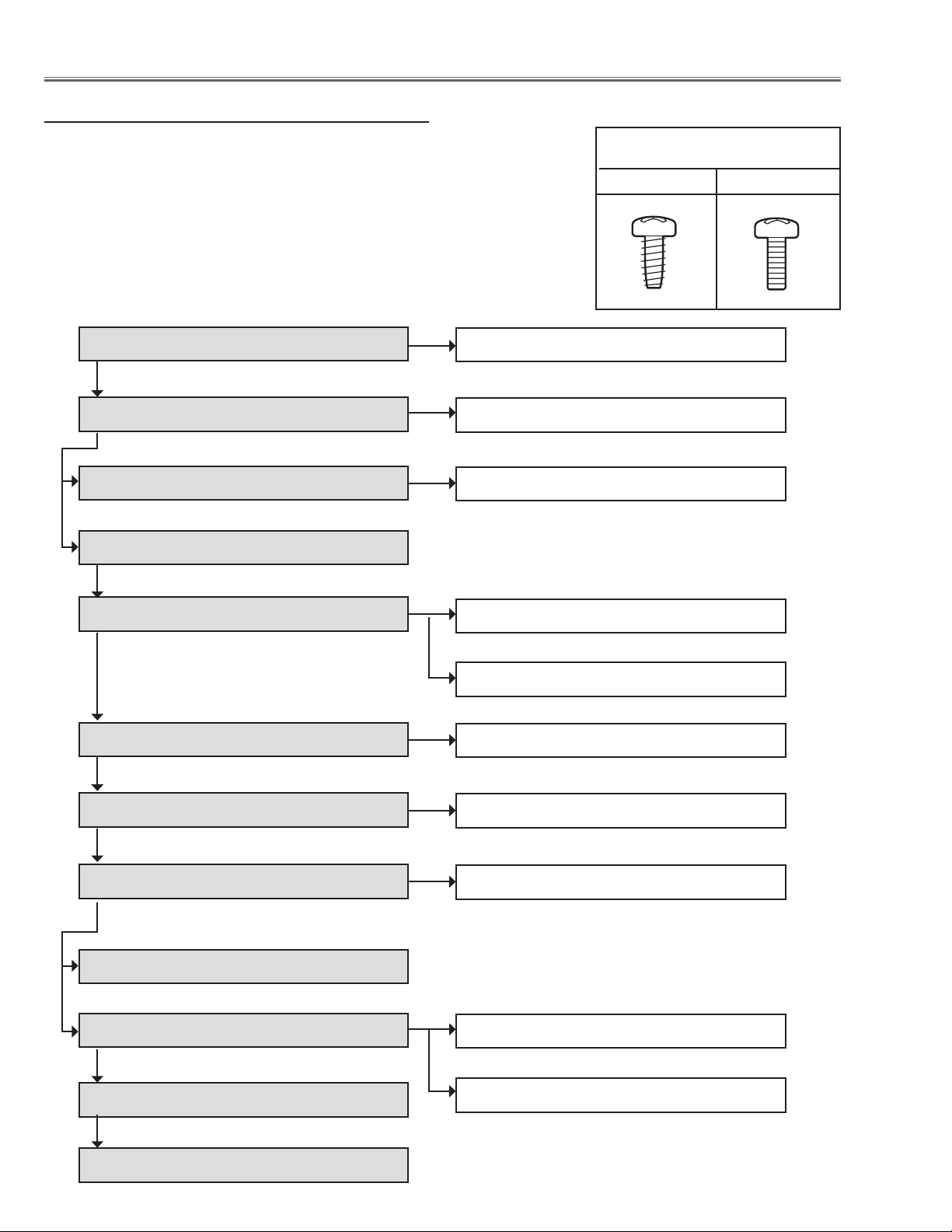
Mechanical disassembly flow chart
Mechanical disassembly should be made by following procedures chart.
Following steps show the basic procedures, therefore unnecessary step may
be ignored.
Caution:
The parts and screws should be placed exactly the same position as the original otherwise it may cause loss of performance and product safety.
The wiring method of the leads and ferrite cores should be returned exactly the
same state as the original, otherwise it may cause lose of performance and
product safety.
Screws Expression
(Type Diameter x Length) mm
T type M Type
1 Cabinet front cover removal
2 Cabinet top removal
3 Control assy and filter cover removal
4 Main board removal
5 Cabinet back & lamp cover removal
6 Power box removal
1-1 Cabinet front disassembly
2-1 LED board removal
3-1 Control board fan (FN907) disassembly
5-1 AV board removal
5-2 Fans (FN904, FN905, FN906) removal
6-1 Power box disassembly
7 Ballast box removal
8 Optical unit removal
9 Cabinet front removal
10 Filter box removal
11 Fan (FN902, FN903, FN908) & duct removal
12 Lens shift cover and shield base removal
7-1 Ballast box disassembly
8-1 Lens shift motor assy removal
10-1 Filter box and fan(FN901) disassembly-1
10-2 Filter box disassembly-2
-16-
020-000423-02 Rev.1 (01-2013)
LHD700 Service Manual
Page 19
Mechanical Disassembly
Mechanical disassembly
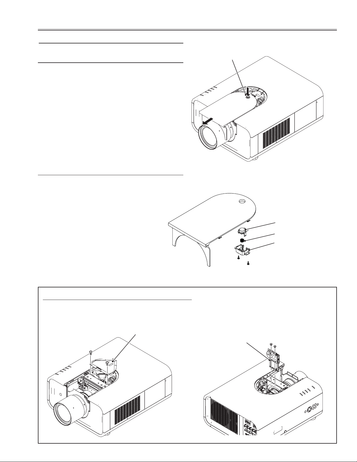
1 Cabinet front cover removal
1 Press the release button and slide the lamp cover to
the arrow direction and remove it.
1-1 Cabinet front cover disassembly
1 Remove 2 screws A (T3x8) and take the release but-
ton, button holder and spring off.
Release Button
Fig. 1-1
Release button
Spring
Shutter assy disassembly
1 Remove 2 screws A (M3x6) and take the prism shield cover off.
2 Remove 2 screws B (M2.5x5) and take the shutter assembly off.
Prism shield cover
A
A
A
A
Shutter assy
Button holder
B
B
LHD700 Service Manual
020-000423-02 Rev.1 (01-2013)
-17-
Page 20
Mechanical Disassembly
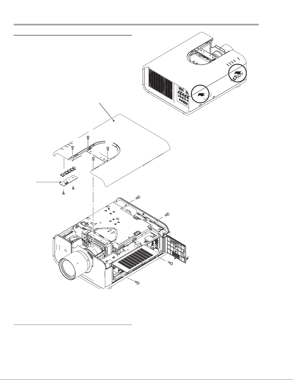
2 Cabinet top removal
1 Open the filter cover and remove 1 screw A (M3x8).
2 Remove 1 screw B (M3x8) and open the lamp cover
and remove 1 screw C (M3x8).
3 Remove 4 screws D (M3x8) on the cabinet top and 2
screws E (M3x8) on the cabinet back.
4 Release the hooks by pressing the side part of cabinet
bottom indicated with the arrows and take the cabinet
top off.
Cabinet top
D
D D
D
Press here to unhook
LED board
E
F
F
E
B
C
A
2-1 LED board removal
1 Remove 2 screws F (T3x8) and take the LED board
and LED holder off.
-18-
Fig. 1-2
LHD700 Service Manual
020-000423-02 Rev.1 (01-2013)
Page 21
Mechanical Disassembly
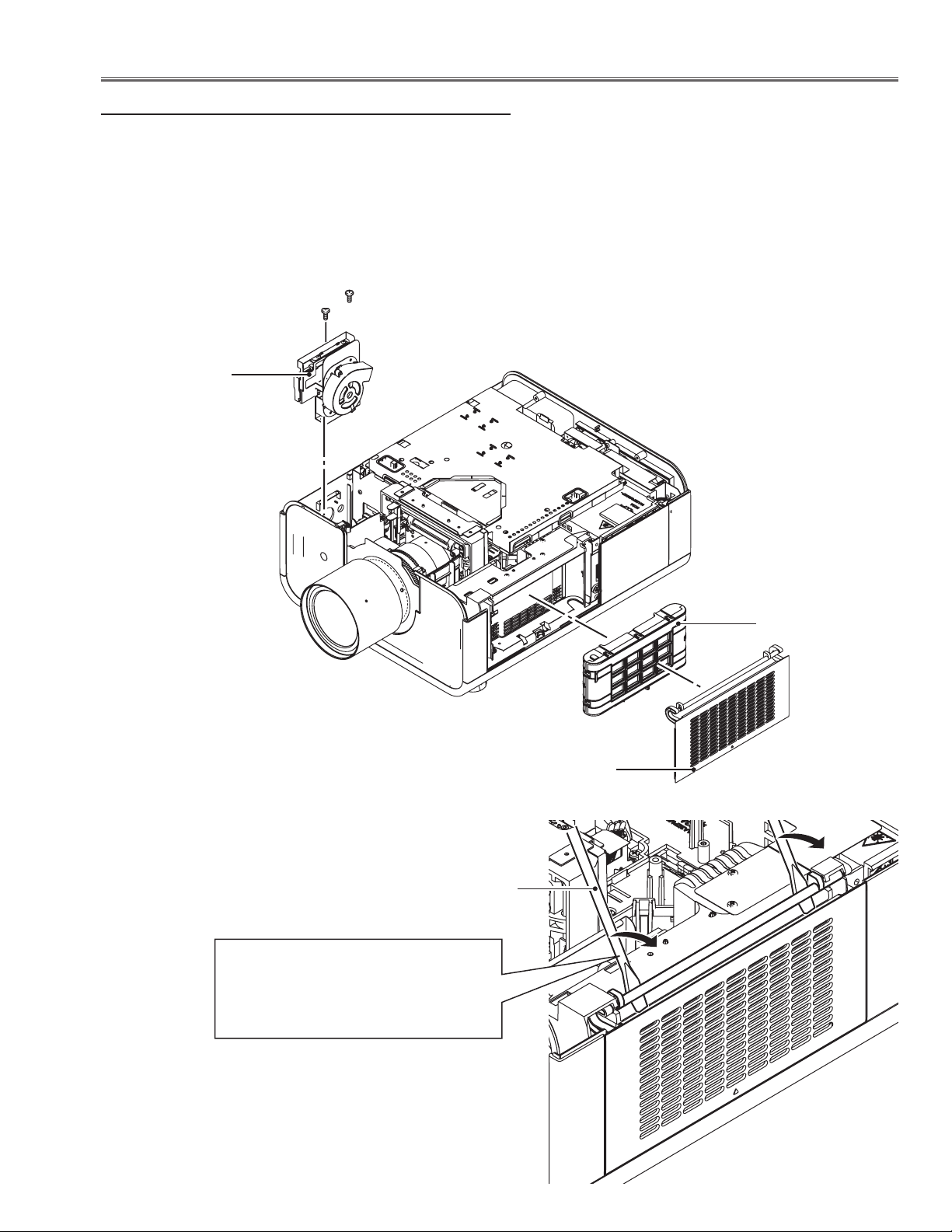
3 Control board assy and cover removal
1 Remove 2 screws A (T3x8) and take the control board &
fan assy upward off.
2 Open the filter cover and take the filter cartridge off.
3 Remove the filter cover off by using a flat screw driver as
shown in the figure.
A
A
Control board &
fan(FN907) assy
Flat screwdriver
Turn the flat screwdriver in the arrow
direction to unhook the filter cover's
hinges.
Note: Be careful not to scratch the filter
cover and holder.
Filter cartridge
Filter cover
LHD700 Service Manual
020-000423-02 Rev.1 (01-2013)
-19-
Page 22

Mechanical Disassembly
3-1 Control board and fan (FN907) disassembly
1 Remove 2 screws B (M3x6) and take the control board/
button holder off
2 Unhook 2 hooks C on the button holder and take the con-
trol board off.
3 Remove 2 screws D (M3x10) and take fan (FN907) off.
C
Control buttons
C
Control board
4 Main board removal
1 Remove 2 screws A (M3x6) and take the prism shield
cover top off.
2 Remove 6 screws B (M3x6) and take the main shield cover
top off.
3 Remove 2 screws C (M3x6) and 1 screw D (M3x6) and
take the main board off.
4 Remove 2 screws E (M3x6) and take the main shield cover
bottom off.
B
B
FN907
D
D
B
B
B
B
B
A
A
B
C
Main
C
board
E
E
D
-20-
LHD700 Service Manual
020-000423-02 Rev.1 (01-2013)
Page 23

Mechanical Disassembly
5 Cabinet back ass’y removal
1 Remove 3 screws A (T3x8), 1 screw B (M3x6) and 1
screw C (M3x6) and take the cabinet back ass’y up-
ward off.
C
A
A
B
A
Lamp cover
5-1 AV board removal
1 Remove 4 screws D (T3x8) and 4 screws E (T3x10-
black) and take the AV board off.
E
D
D
D
D
AV board
F
5-2 Fans (FN904, FN905, FN906) removal
1 Remove 6 screws F (T3x8) and take the fans (FN904,
FN905, FN906) off.
FN905
FN906
F
F
F
F
FN904
F
LHD700 Service Manual
020-000423-02 Rev.1 (01-2013)
-21-
Page 24
Mechanical Disassembly
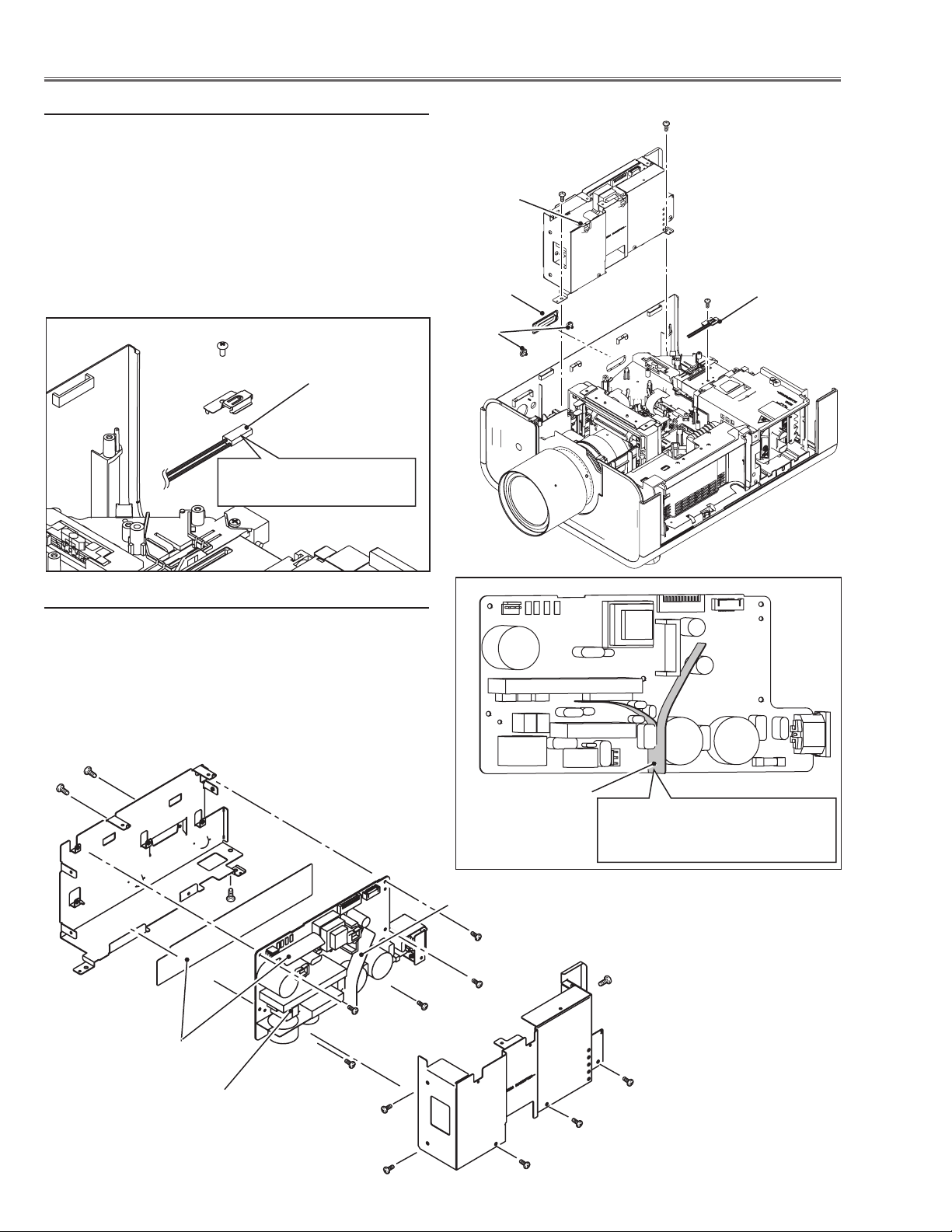
6 Power Box removal
1 Remove 3 covers A and B on the cabinet.
2 Remove 1 screw C (M3x6) and take thermal protector
(SW905) off
3 Disconnect the socket D (K6B) on the power board.
4 Remove 2 screws E (M4x8) and take the power box
upward off.
E
E
D
Thermal protector
(SW905)
Note: Mount as the printed
mark comes up side.
6-1 Power box disassembly
1 Remove 6 screws F (M3x6) and take the power box
cover off.
2 Remove 5 screws G (M3x6), 1 screw H (M4x8), 2
screws J (M2.8x4) and take the power board off.
B
Thermal protec-
C
tor (SW905)
A
J
Isolation sheet
Note:
The isolation sheet must be placed
as shown in the figure above.
Isolation sheet
H
G
F
G
G
G
Insulation sheet
Power board
G
F
F
F
F
-22-
F
LHD700 Service Manual
020-000423-02 Rev.1 (01-2013)
Page 25
Mechanical Disassembly
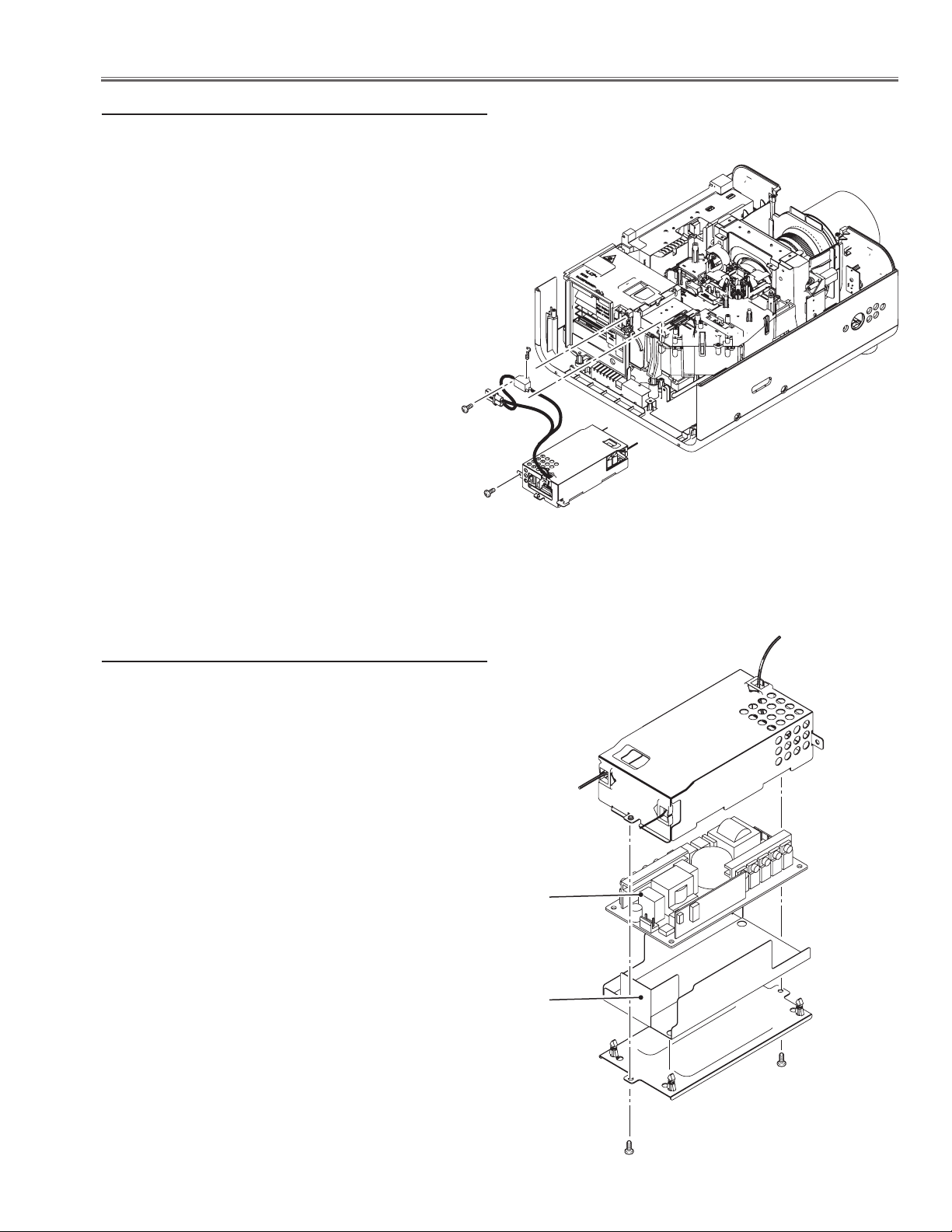
7 Ballast box removal
1 Remove 1 screw A (M3x6) and disconnect the lamp
ballast socket.
2 Remove 1 screw B (T3x10) and take the ballast trigger
off.
3 Remove 1 screw C (M4x8) and pull the ballast box
backward and remove it off.
A
C
B
7-1 Ballast box disassembly
1 Remove 2 screws D (M3x6) and take the shield case
top off
2 Remove ballast board from the shield case bottom.
Ballast board
Isolation sheet
D
LHD700 Service Manual
020-000423-02 Rev.1 (01-2013)
D
-23-
Page 26
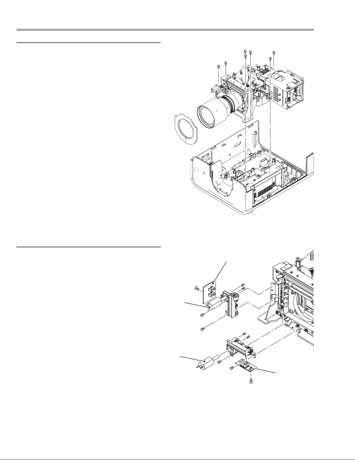
Mechanical Disassembly
8 Optical unit removal
1 Remove 7 screws A (T4x16), disconnect ballast socket
and take the optical unit upward off.
A
A
A
A
A
A
A
8-1 Lens shift motor ass’y removal
1 Remove 2 screws B (M3x6) and take the lens shift mo-
tor ass’y off.
2 Remove 1 screw C (T3x6) and take the lens shift sen-
sor board off.
3 Remove 2 screws D (T2x4) and take the lens shift mo-
tor off
Lens shift motor
Lens shift motor
Sensor board
D
C
B
B
B
B
D
Sensor board
C
-24-
LHD700 Service Manual
020-000423-02 Rev.1 (01-2013)
Page 27

Mechanical Disassembly
9 Cabinet front removal
1 Remove 4 screws A (T3x8) and take the cabinet front
upward off.
2 Remove 1 screw B (T3x8) and take the RC front board
off.
A
RC front board
A
B
A
A
LHD700 Service Manual
020-000423-02 Rev.1 (01-2013)
-25-
Page 28
Mechanical Disassembly
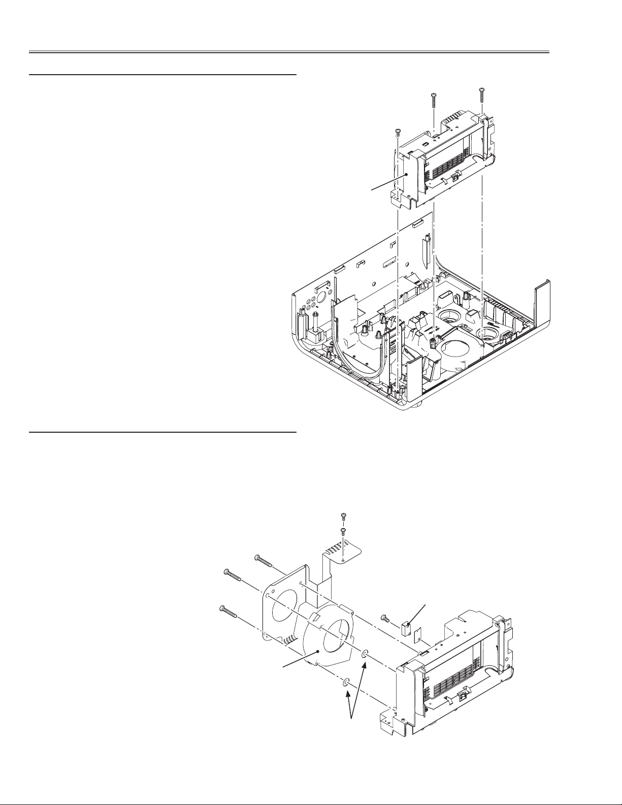
10 Filter box removal
1 Remove 1 screws A (T3x8), 2 screws B (T4x40) and take
filter box upward off.
Filter box
B
B
A
10-1 Filter box and fan (FN901) disassembly-1
1 Remove 2 screws C (T3x8), 3 screws D (T4x35), and take
fan (FN901) and holder off.
2 Remove 1 screw E (T3x14) and take the wind sensor
(S901) off.
D
D
D
FN901
C
C
E
S901
-26-
Washers
LHD700 Service Manual
020-000423-02 Rev.1 (01-2013)
Page 29
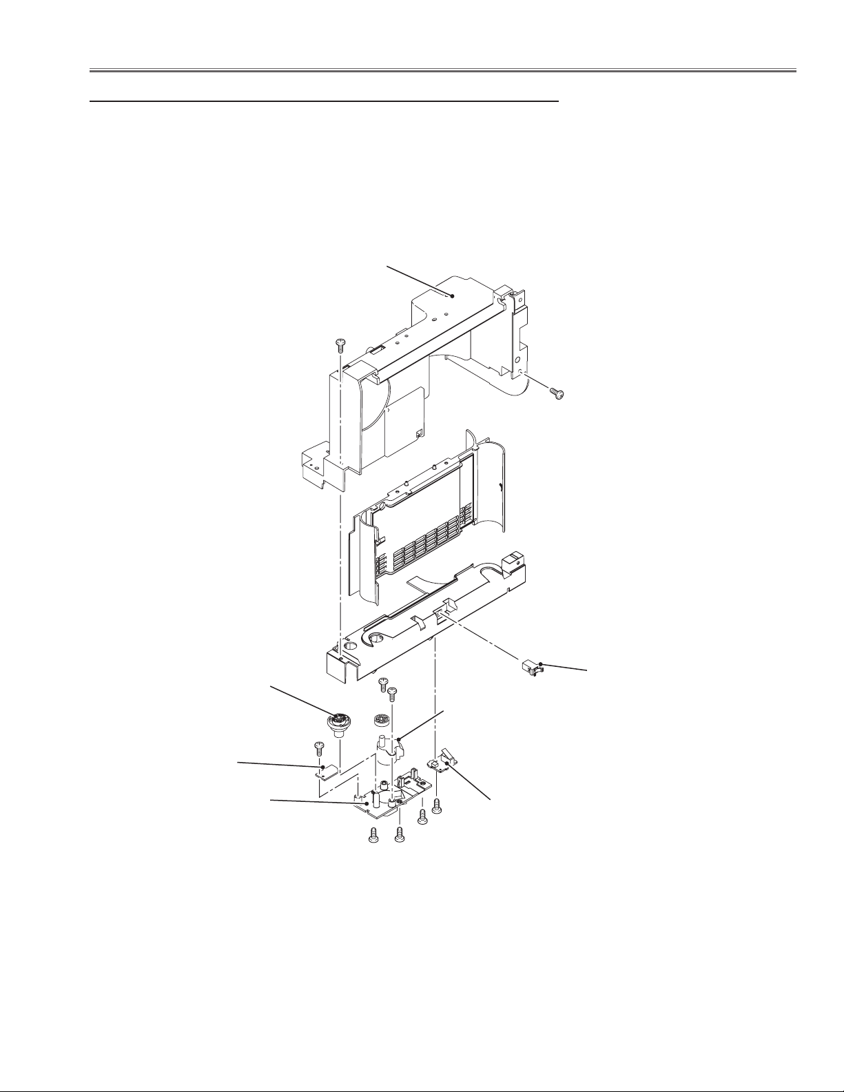
Mechanical Disassembly
10-2 Filter box disassembly-2
1 Remove 2 screws E (T3x8) and take the filter cover off.
2 Take the filter cover latch off by pulling it.
3 Remove 3 screws F (T3x8) and take the filter bottom cover off.
4 Take the filter switch board off, and remove 1 screw G(T3x8) and take the
filter round sensor board off.
5 Remove 2 screws H (T4x8) and filter motor off.
Filter holder
cover
E
E
Filter shaft
Filter round
sensor board
Filter bottom
LHD700 Service Manual
020-000423-02 Rev.1 (01-2013)
holder
cover
G
F F
H
Latch
H
Filter motor
Filter switch
board
F
F
-27-
Page 30
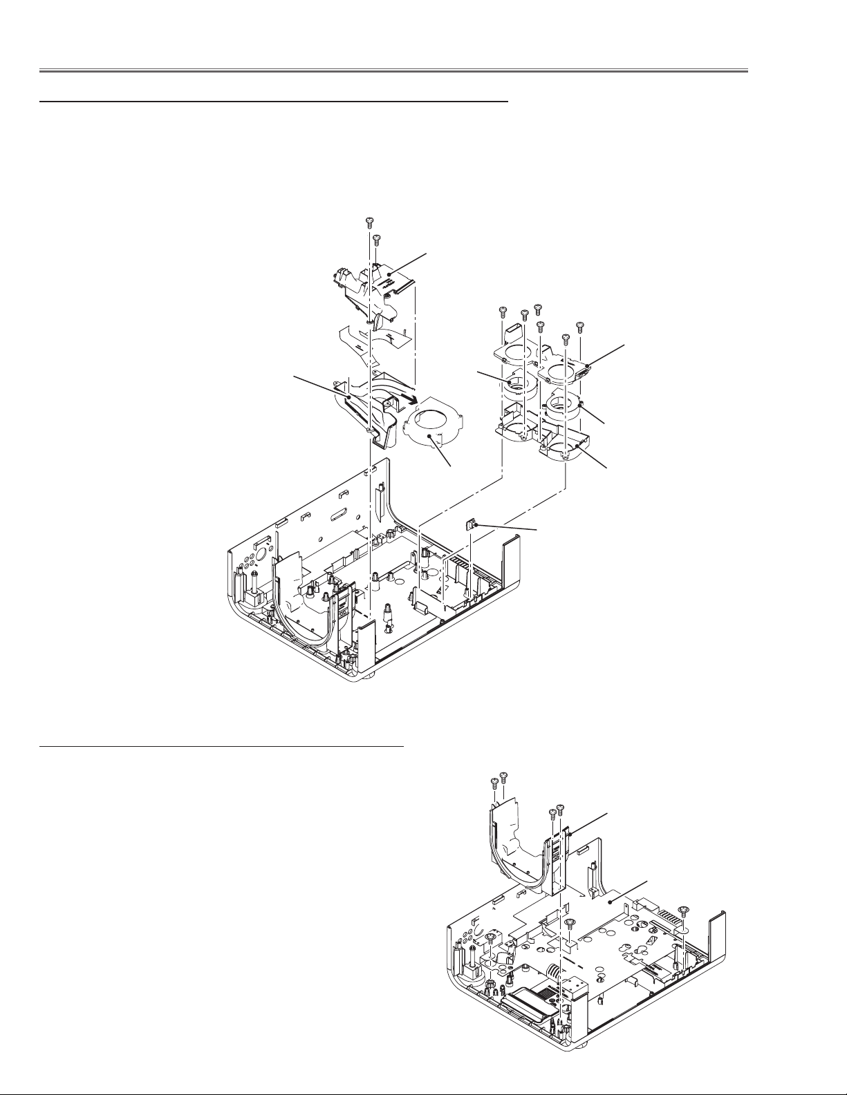
Mechanical Disassembly
11 Fans (FN902, FN903, FN908) and duct removal
1 Remove fan (FN902) upward off.
2 Remove 2 screws A (T3x8) and take the duct top (LCD) upward off.
3 Remove 6 screws B (T3x8) and take the duct (PBS) assy upward off and
remove fans (FN908 and FN903) off.
4 Remove the lamp cover switch board off.
A
A
Duct top
(LCD)
B
B
B
B
Duct top (PBS)
Duct bottom
(LCD)
12 Lens shift cover and shield base removal
1 Remove 4 screws A (T3x8) to remove the lens shift
cover.
2 Remove 3 screws B (T4x8) to remove the shield base from
the cabinet bottom.
FN908
FN902
FN903
Duct bottom (PBS)
Lamp cover
switch board
A
A
Lens shift cover
-28-
Shield base
B
B
B
LHD700 Service Manual
020-000423-02 Rev.1 (01-2013)
Page 31
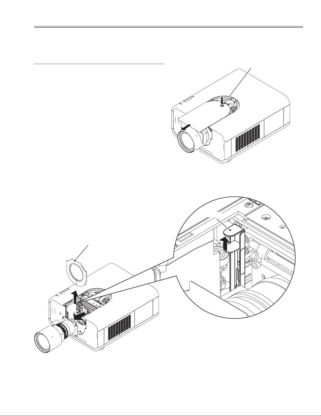
Optical Parts Disassembly
Disassembly requires a 2.0mm or 2.5mm hex wrench and a slot screwdriver.
1 Projection lens removal
1 Set the projection lens to center position with lens shift
function.
2 Press and hold the release button on the cabinet front
cover and slide it in the arrow direction as shown in the
figure and open it.
3 Remove the light block plate upward off.
4 Slide the lens lock lever A on the projector to “UN-
LOCK” (UPPER) position and remove the Projection
Lens ass’y off.
Note : When making unlocking, attach your hand to pre-
vent the lens fall.
Release button
Light block plate
Lever A
LHD700 Service Manual
020-000423-02 Rev.1 (01-2013)
-29-
Page 32
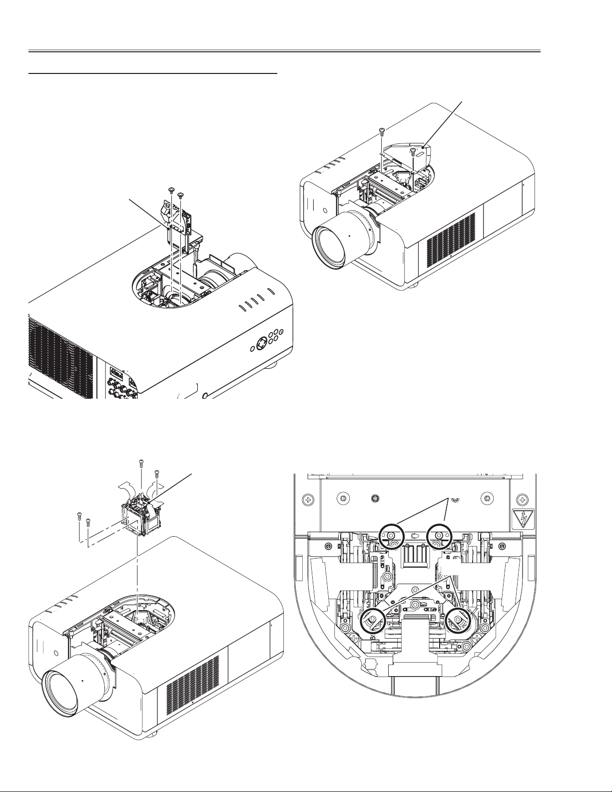
Optical Parts Disassembly
2 LCD panel/Prism assy removal
1 Remove 2 screws A (M3x6) and take the prism shield
cover off.
2 Remove 2 screws B (M2.5x5) and take the shutter assy
upword off.
3 Remove 4 screws C (M2.5 x10) and take the LCD pan-
el/prism assembly upward off.
B
Shutter assembly
B
Prism shield cover
A
A
C
LCD panel/prism
C
assembly
C
C
C
C
-30-
LHD700 Service Manual
020-000423-02 Rev.1 (01-2013)
Page 33
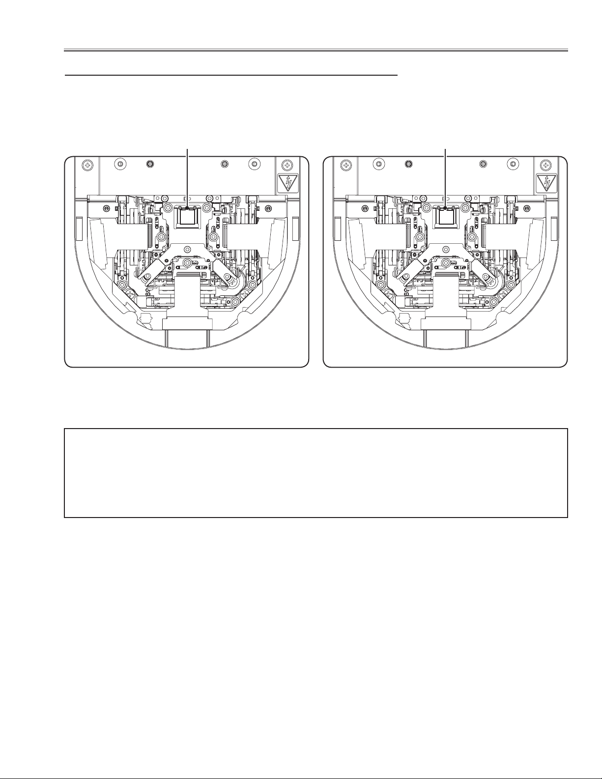
Optical Parts Disassembly
LCD Panel Type Check
There are 2 types of the LCD panel/prism assembly, named Type-R and Type-L. When replacing the LCD panel/
prism assy, use the same type of the one on the projector.
Confirm the "R" label or "L" label on top of the LCD panel/ prism assembly to identify the type.
Indication of Type-R
R
LCD Panel/Prism Assy (Type-R)
Indication of Type-L
L
LCD Panel/Prism Assy (Type-L)
IMPORTANT NOTICE on LCD panel/prism assy replacement
LCD panels used for this model cannot be replaced separately. Do not disassemble the LCD panel/prism assy.
These LCD panels are installed with precision at the factory. When replacing the LCD panel, should be replaced
whole of the LCD panels and prism assy at once.
When replacing LCD panel/prism assy, take the optical and electrical adjustments following to the chapter "Adjustment".
LHD700 Service Manual
020-000423-02 Rev.1 (01-2013)
-31-
Page 34
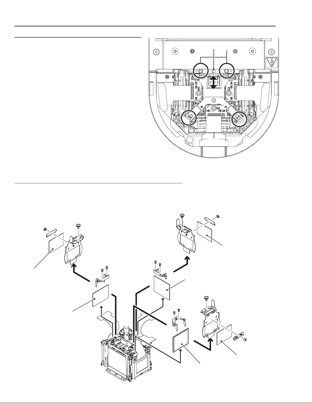
Optical Parts Disassembly
Note on LCD panel/prism assy mounting
After replacing or installing the LCD panel/prism assy,
please make sure to obtain the best focus in both TELE
and WIDE zoom. If the focus adjustment is required,
please adjust the positioning of LCD panel/prism assy
following to the procedure below.
Focus adjustment:
1 Loosen 4 screws A on the LCD Panel/Prism ass’y with
2.0 mm hex driver.
2 Turn the projector on and project the image with WIDE
zoom, and adjust the FOCUS control to obtain the best
focus.
3 Turn the ZOOM control to the TELE position.
4 Insert a flat screw driver into the slot B and move the
LCD panel/prism assy backward or forward by turning
the screwdriver left or right to obtain the proper focus.
Confirm the focus at TELE and WIDE zoom.
5 Tighten 4 screws A to fix the LCD panel/prism assy.
2-1 Polarized glass (OUT) and optical filter (ICV) removal
1 Remove 1 screw D (M2.5x6) on each holder and take the optical filter
(ICV) assy upward off.
2 Remove 2 screws E (M2x4) to remove the holder and then take the polar-
ized glass (OUT) upward off.
D
D
B
A
A
(M2x2)
(M2x2)
Optical filter (ICV)
Polarized glass(OUT/B)1
Optical filter (ICV)
E
E
(Green)
Polarized glass(OUT/G)1
D
E
(M2x2)
(Blue)
Optical filter (ICV)
Polarized glass(OUT/R)1
-32-
(Red)
LHD700 Service Manual
020-000423-02 Rev.1 (01-2013)
Page 35
Optical Parts Disassembly
2-2 Polarized glass (OUT)/Optical filter (ICV) mounting
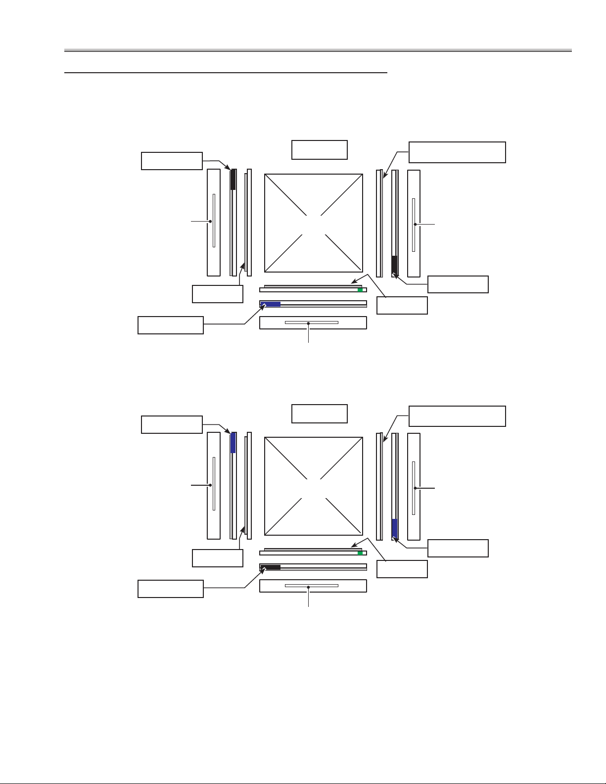
There are 2 types of the LCD panel/prism assembly named Type-R and Type-L. Mount the polarized glasses (OUT)
and optical filters (ICV) according to the type of the LCD panel/prism assembly as shown in the figure below.
LCD panel/prism top view
Black Marker
R-LCD panel
Violet Marker
Violet Marker
Film side
TYPE-L
Prism
G-LCD panel
TYPE-R
Brown colored side
B-LCD panel
Black Marker
Film side
Brown colored side
R-LCD panel
Black Marker
LHD700 Service Manual
020-000423-02 Rev.1 (01-2013)
Film side
Prism
G-LCD panel
-33-
B-LCD panel
Violet Marker
Film side
Page 36
Optical Parts Disassembly
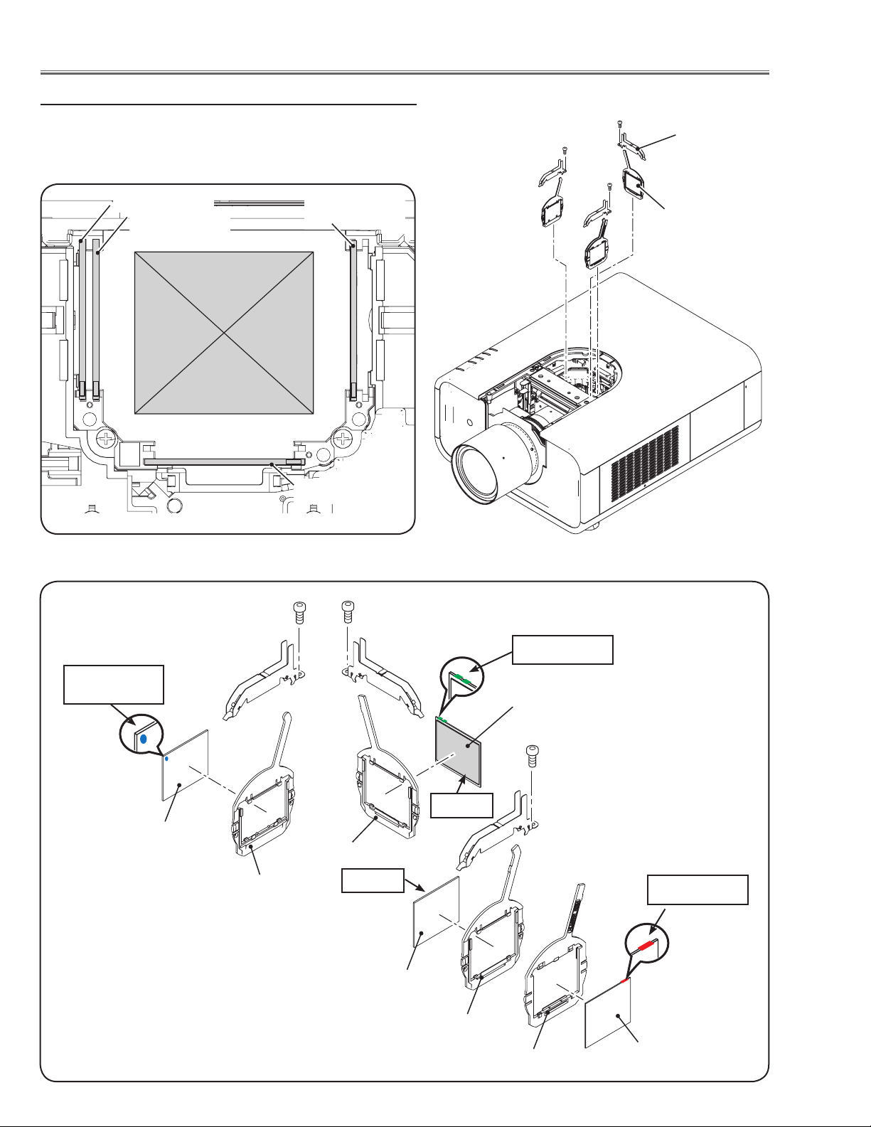
3 Polarized glass(IN) assy removal
1 Remove 1 screw A (M2.5x5) on each stopper and take the
polarized glasses upward off.
R-holder A
R-holder
Red
Green
B-holder
Blue
G-holder A
A
A
Stopper
A
Polarized glass
(IN) assy
Blue marker
(Behind)
Polarized glass(IN/B)1
Blue
B-holder
G-holder A
Film side
Polarized glass(IN/R)
Green
Green marker
Polarized glass(IN/G)2
Film side
Red marker
Red
R-holder
-34-
R-holder A
Polarized glass(IN/R)1
LHD700 Service Manual
020-000423-02 Rev.1 (01-2013)
Page 37
Optical Parts Disassembly
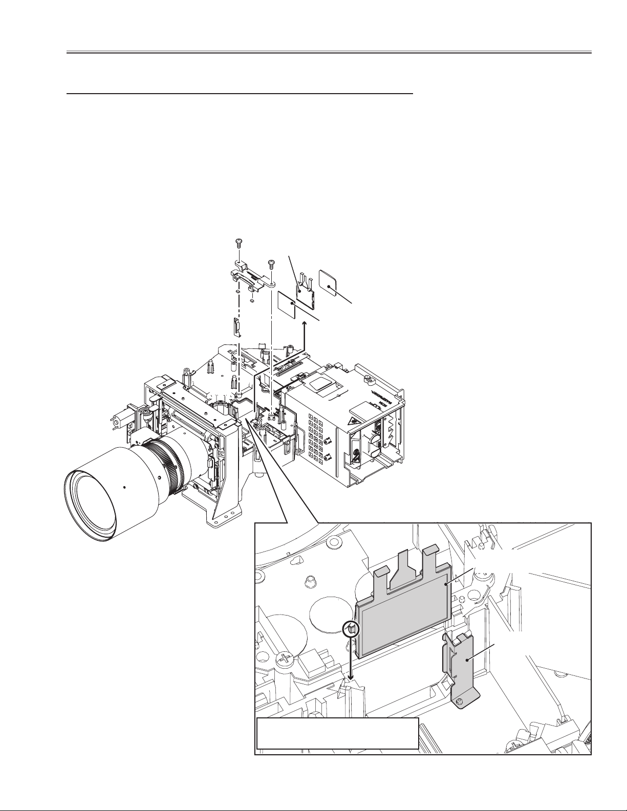
4 Optical filter, Polarized glass (IN/GB), Condenser lens (G)
removal
Before taking this procedure, remove Cabinet top and Main board following
to the chapter "Mechanical Disassembly".
1 Remove 2 screws A (M3x8) and remove the optical filter cover.
2 Remove the optical filter (LC-CS), polarized glass (IN/GB) and condenser
lens (G) upward off.
A
Optical filter (LC-CS)
A
Condenser lens (G)
Polarized glass (IN/GB)
LHD700 Service Manual
020-000423-02 Rev.1 (01-2013)
Optical filter (LC-CS)
Stopper G
* Mount the optical filter (LC-CS) as
shown in the figure.
-35-
Page 38
Optical Parts Disassembly
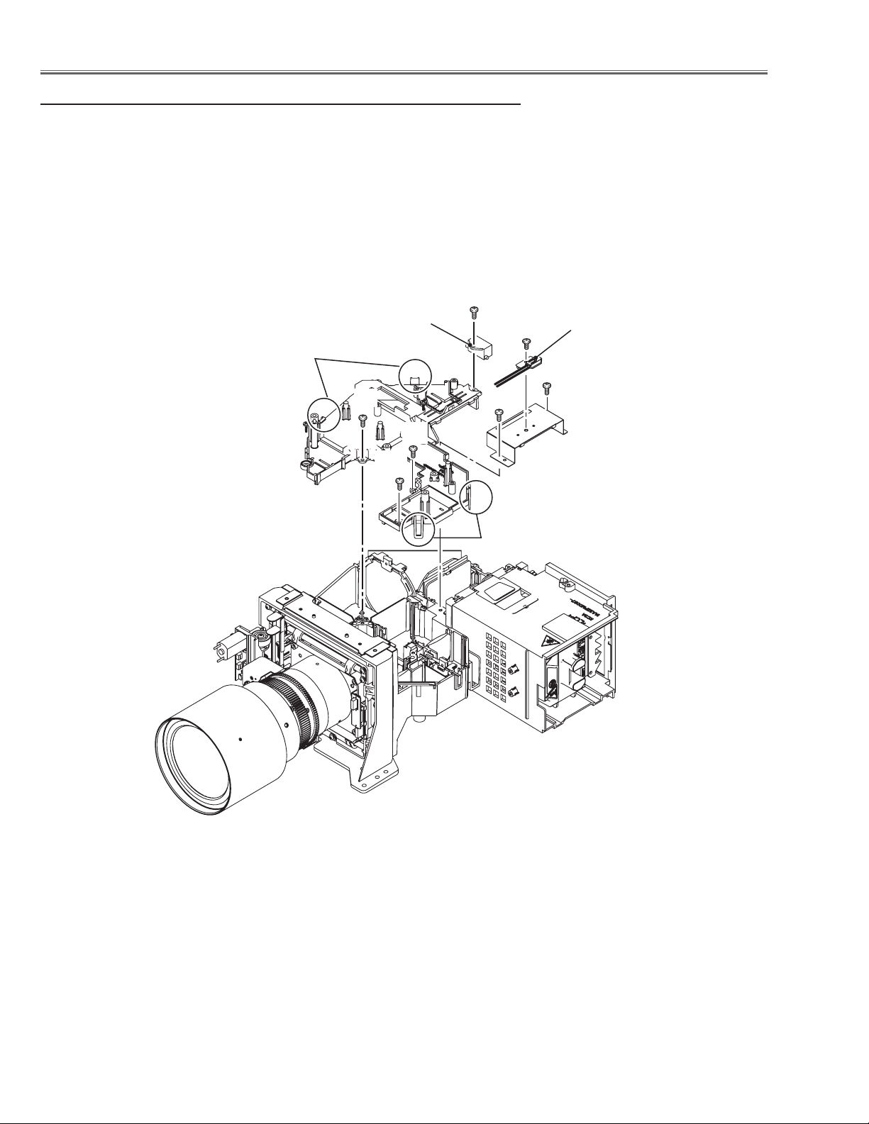
5 Optical base top removal
Before taking this procedure, remove cabinet top, main board following to the
chapter "Mechanical disassembly".
1 Remove 1 screw A (M3x6) on the thermal protector, 1 screw B (T3x10) on
the ballast trigger and 5 screws C (T3x10).
2 Unhook 4 hooks D on the optical base top and take the optical base top
upward off.
B
D
Ballast trigger
C
C
C
A
Thermal protector
C
C
D
-36-
LHD700 Service Manual
020-000423-02 Rev.1 (01-2013)
Page 39
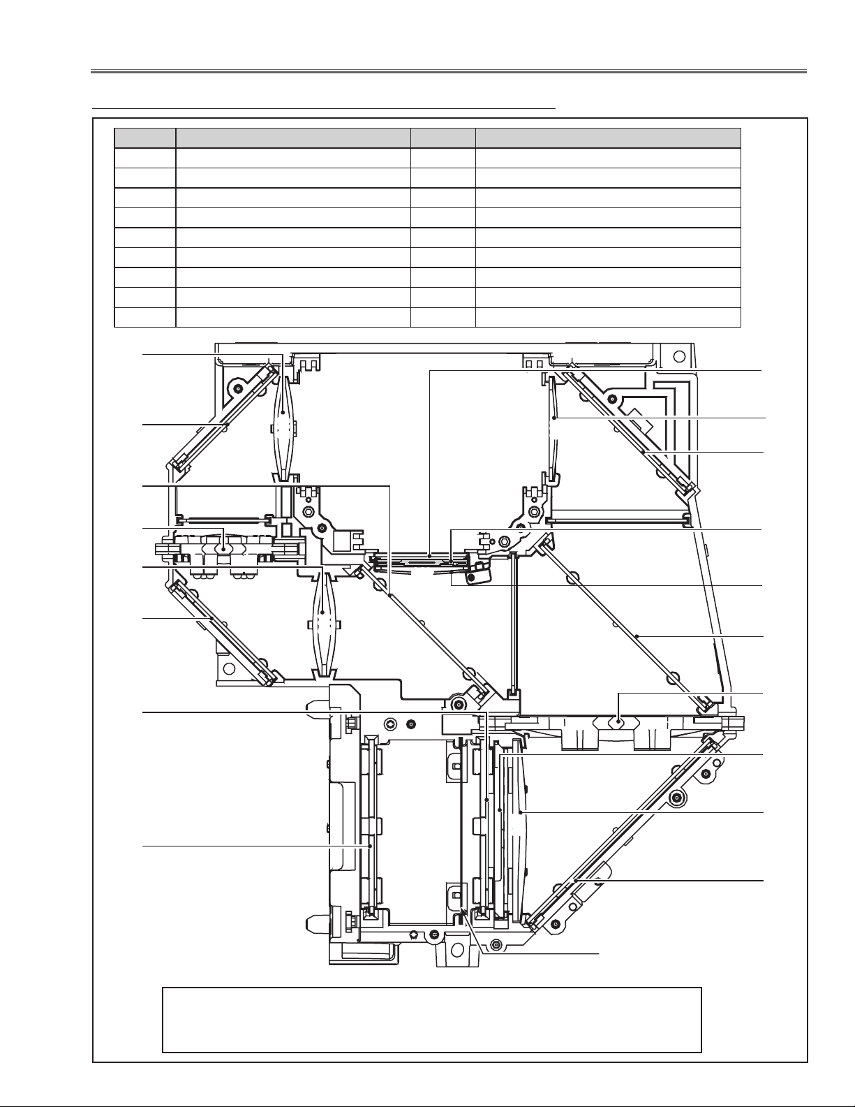
Optical Parts Disassembly
238
241
240
238
490
490
489603
241
240
5-1 Optical parts locations in the optical unit
No. Parts Name No. Parts Name
1 LENS,INTEGRATOR(IN) * 10 LENS,RELAY(IN)
2 LENS,INTEGRATOR(OUT) * 11 LENS,RELAY(OUT) *
3 ASSY,PRISM(PBS) 12 LENS,CONDENSER(R)
4 LENS,CONDENSER(IN) 13 MIRROR(B)
5 MIRROR(W-COLD) 14 POLARIZED GLASS(IN/GB)
6 LENS,CONDERSOR(OUT) * 15 LENS,CONDENSER(G)
7 DICHROIC MIRROR (B) 16 LENS,CONDENSER(B)
8 DICHROIC MIRROR (G) 17 OPTICAL FILTER (LC-CS)
9 MIRROR(R)
12
14
11
10
9
8
16
13
17
15
9
7
6
2
3
4
1
Note:
The parts indicated with (*) are fixed with the adhesive onto the optical base bottom,
so these parts are not the replaceable parts.
LHD700 Service Manual
020-000423-02 Rev.1 (01-2013)
5
Shield Plate
-37-
Page 40

Optical Parts Disassembly
5-2 Optical parts directions in the optical unit
When mounting or assembling the optical parts in the optical unit, the parts must be mounted in the specified location
and direction as shown in the figure below.
Polarized glass (IN /GB)
Mount as the marker facing to the prism side as shown
in the figure below.
Printed marker
Mirror, Dichroic mi
rror
Place the mirror and dichroic mirror into the groove
and then mount the stoppers to fix them.
Stopper
Dichroic mirror
Mount them as shown in the figure below. Pay attention to the direction of the
printed parts no. on the mirror.
Printed marker
Printed marker
-38-
LHD700 Service Manual
020-000423-02 Rev.1 (01-2013)
Page 41
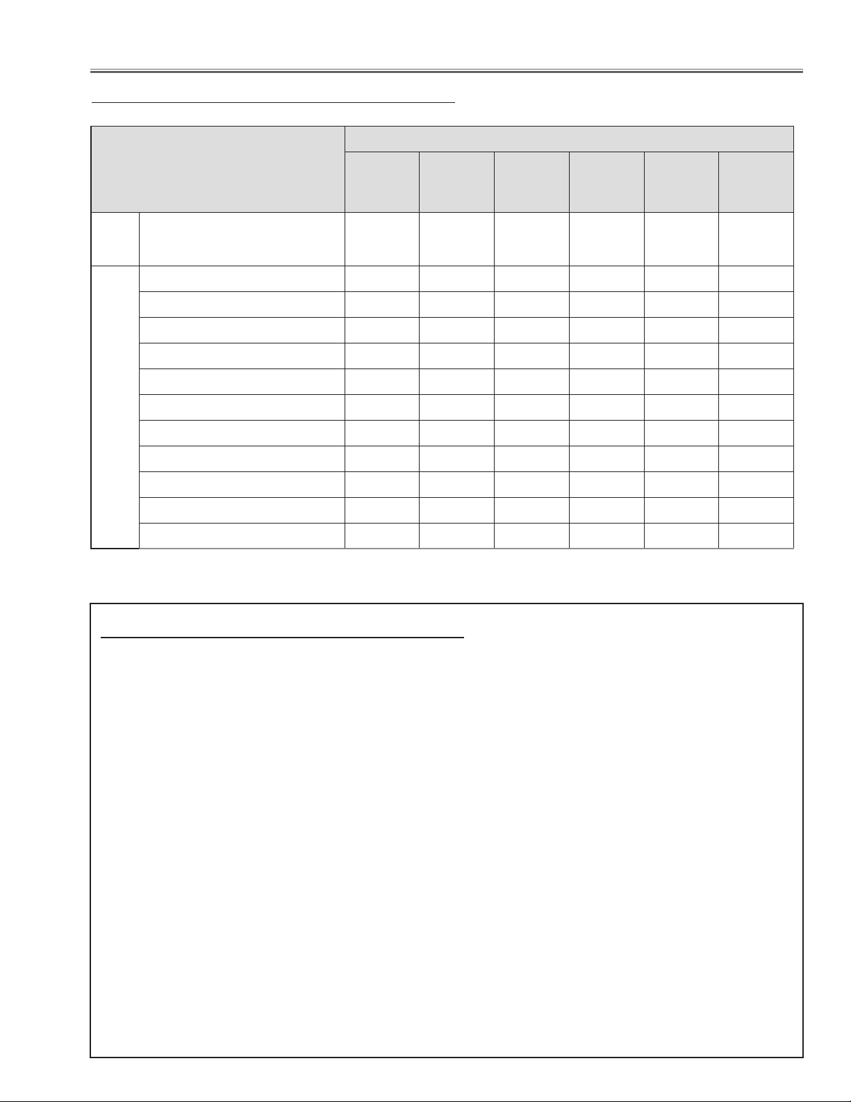
Adjustments
Adjustments after parts replacement
LCD/
Prism Ass’y
Optical
Adj.
Contrast adjustment
● ● ●
Disassembly / replaced parts
Polarized
Glass/
optical filter
(ICV)
●: Adjustment necessary ❍: Check necessary
Optical Filter
(Ye Device)
Power Board Main Board
Fan s/
Wind Sens or
LCD panel L/R setting
Fan voltage adjustment
Electrical Adjustments
PC-auto calibration
Video-auto calibration
Component-auto calibration
Common voltage adjustment
Gamma shipment setting-up *
Ye-superimposed shipment setting-up *
Color shading correction adjustment *
White balance adjustment
Wind sensor calibration
* To setup or adjust those items, the Projector Service Tool v. 4.20 software is needed. Refer to the owner's manual for this
software for the further details.
● ●
● ●
● ●
❍ ❍ ❍ ●
❍ ❍ ❍ ●
● ● ●(S9 01)
●
● ●( Fans)
●
●
●
Note on main board replacement
Take the following setting when the main board is replaced.
- Shipment data setting (Color Shading Correction, Gamma Shipment, Ye-Superimposed Shipment)
- Serial No. Setting
Adjustment Ship Data Setting
This projector stores "Color Shading Correction Data", "Gamma Data" and "Ye-Superimposed Data" in the flash memory (IC801) and memory (IC1387) on the main board. Those shipping data have been setup according to the optical
characteristics of the mounted LCD panels and Ye device (Optical Filter) preciously in the factory. When replacing
the main board, you need to read out the those setting data stored in the memory ICs on the previous main board
and write down them into the memory ICs on the new main board. By this way, the projector enables to reproduce the
picture which has properly adjusted color shading correction, gamma correction and Ye characteristics. If it is not possible to read out the data, or replace the LCD/Prism assy or Ye device (Optical Filter), you seed to write the initial data
which is setting the typical characteristics of the LCD panel and Ye device into the flash memory on the new board.
For further details, refer to the operation manual of the software [PROJECTOR SERVICE TOOL v4.20].
Serial No. Setting
Each projector has an unique serial no. controlled in the factory. There are 2 ways to check this serial no. The
one is printed on the rating label on the cabinet, the other one is displayed on the "Information" on the on-screen
menu. The serial no. displayed on the on-screen menu is stored in the memory IC (IC1387) on the main board.
When replacing the main board or memory IC, you need to write the serial no. referring to the serial no. printed
on the rating label with the serial no. setting tool. For further details, refer to the operation manual of the serial no.
setting tool [SST LITE v1.00].
Those software are including in the service CD-ROM listed below;
PROJECTOR SERVICE TOOL CD-ROM v4.21 SERVICE CODE: 610 357 7548
LHD700 Service Manual
020-000423-02 Rev.1 (01-2013)
-39-
Page 42
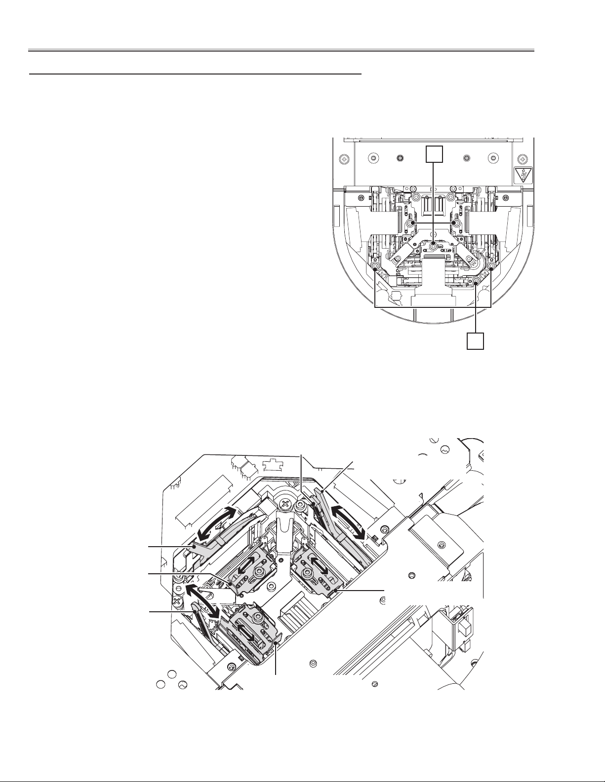
Optical Adjustments
Contrast adjustment
Adjustment environment: Dark room
Signal pattern: All black ( Select the internal test pattern signal “All
black” from the projector’s menu “Menu
-> Setting -> Test pattern”.)
[1] Polarized glass adjustment
1 Loosen each screw A on the polarized glass holder.
2 Turn the lever B of polarized glass to obtain the darkest brightness
and proper black color uniformity on the screen.
Adjust in order for G-panel, R-panel and then B-panel.
3 Turn the lever C of polarized glass for R-panel to obtain the darkest
brightness and proper black color uniformity on the screen.
4 Tighten the screw A to fix the polarized glass holder.
[2] Optical filter (ICV) adjustment
1 Loosen each screw D.
2 Turn the lever E of optical filter (ICV) to obtain the darkest bright-
ness and proper black color uniformity on the screen.
3 Tighten the screw D to fix the optical filter holder.
D
A
Lever B
Polarized glass(IN/G)
Lever E
Optical filer (ICV)
Lever B
Polarized glass(IN/B)
Lever B
Polarized glass(IN/R)
Lever C
Polarized glass(IN/R)
Lever E
Optical filer (ICV)
Lever E
Optical filer (ICV)
-40-
LHD700 Service Manual
020-000423-02 Rev.1 (01-2013)
Page 43

Service Mode
Input Video
Group No. Data
0 0 32
Ver. R 1.00
Electrical Adjustments
Service Adjustment Menu Operation
To enter the service mode
To enter the “Service Mode”, press and hold the MENU and SELECT button on the projector or remote control for
more than 3 seconds. The service menu appears on the screen as follows.
To adjust service data
Select the adjustment group no. by pressing the MENU button (increase) or SELECT button (decrease), and
select the adjustment item no. by pressing the pointer U or V button, and change the data value by pressing the
W or X button. Refer to the “Service Adjustment Data Table” for further description of adjustment group no., item
no. and data value.
To exit the service mode
To exit the service mode, press the ON/STAND-BY button.
Group No.
Memory IC (IC1387) Replacement
Memory IC on the main board stores the data for the
service adjustments, and should not be replaced except for the case of defective device.
If replaced, the re-adjustments are required following to
the “Electrical Adjustments”.
The data of lamp replacement counter is stored in the
Memory IC.
Please note that the lamp replace counter will be reset
when the memory IC is replaced.
(Lamp replace counter cannot be set to the previous
value.)
●Caution to memory IC replacement
When memory IC is replaced with new one, the CPU
writes down the default data of the service adjustments
to the replaced ICs as the mentioned on the service adjustment table. As these data are not the same data as
Item No.
Data value
factory shipped data, it should be required to perform
the re-adjustments following to the “Electrical Adjustments”.
Please note that in this case the lamp replace counter
will be reset.
●Caution of Main Board replacement (in the case
memory IC is not defective)
When the main board is replaced, memory IC should
be replaced with the one on previous main board. After
replacement, it should be required to perform the re-adjustments following to the “Electrical Adjustments”.
In this case, the value of lamp replace counter can be
kept as before.
LHD700 Service Manual
020-000423-02 Rev.1 (01-2013)
-41-
Page 44
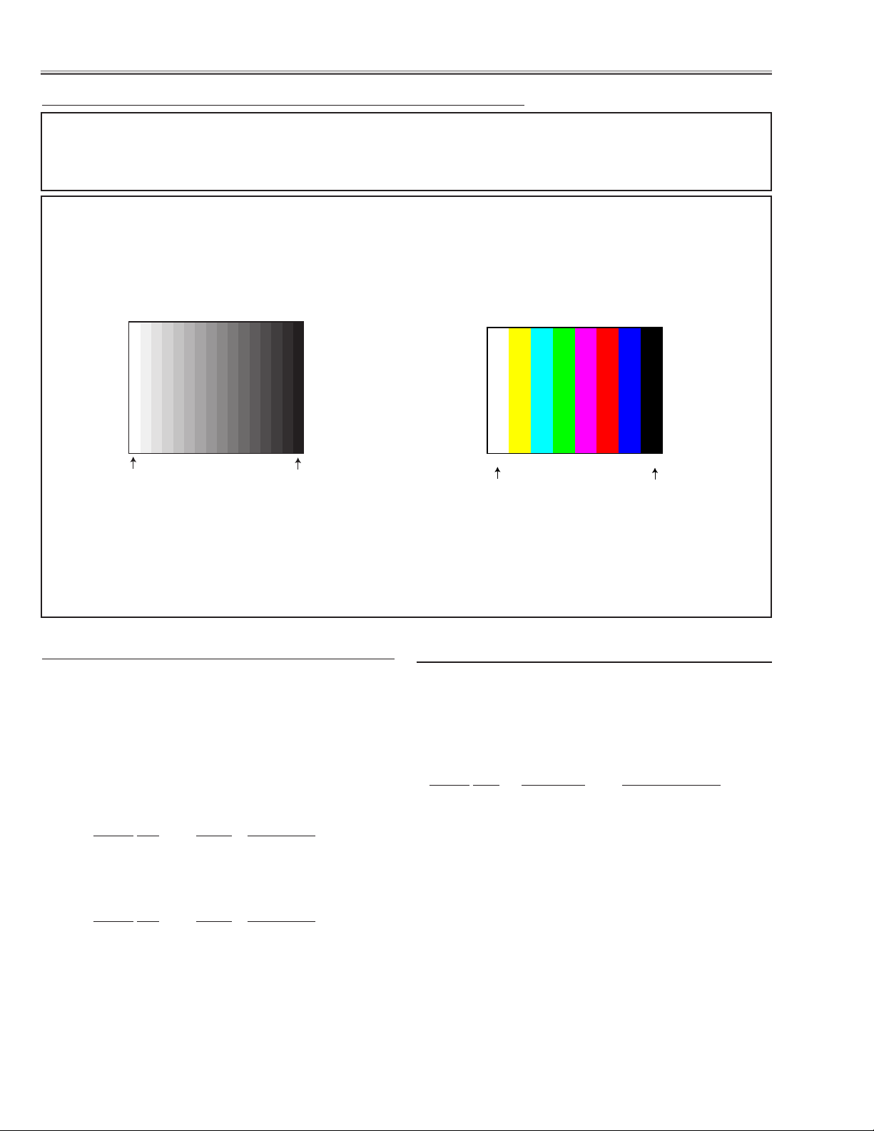
Electrical Adjustment
White 100%
White 0%
W Y C G M R B BK
White 100%
White 0%
Circuit Adjustments
CAUTION: The each circuit has been made by the fine adjustment at factory. Do not attempt to adjust the following
adjustments except requiring the readjustments in servicing otherwise it may cause loss of performance
and product safety. Before taking these adjustments, turn the projector for more than 10 minutes to stabilize the operation.
[Adjustment Condition]
● Input signal
Analog Computer signal ..... 0.7Vp-p/75W terminated (XGA)
Composite Video signal ...
Component Video signal .... 1.0Vp-p/75W terminated (480i, 480p, 720p, 1080i)
1.0Vp-p/75W terminated (NTSC / PAL)
16 steps gray scale pattern
● Image mode ........................
● Lamp mode.........................
“Standard”
“Normal”
● Advanced color ....................
● Screen ..................................
8 color 100% full color bar
“Off”
“Normal”
Note:
* Please refer to “Service Adjustment Menu Operation” for entering the service mode and adjusting the service data.
LCD panel L/R setting
z
There are two type( Type L, Type R) for the LCD/Prism
x Fan Voltages adjustment
Equipment Digital voltmeter
Assy. The adjustment data is stored in the memory IC
on the main board.
As the used type is indicated on the LCDpanel/prism
assy, perform this adjustment to match to its type indica-
1. Enter the service mode.
2. Change data values of each test point to adjust the fan
driving voltage.
tion.
1. Enter the service mode.
2. Check the data value. (290 - 0)
Group No. Value Panel type
290 - 0 0 L
290 - 0 20 R
Group No. Test Point
250 - 0 TPFN1 5.0 +0.1 -0Vdc
250 - 1 TPFN1 13.8 +0 -0.1Vdc
250 - 2 TPFN2 4.0 +0.1 -0Vdc
250 - 3 TPFN2 13.8 +0 -0.1Vdc
Adjustment value
250 - 4 TPFN3 5.0 +0.1 -0Vdc
3. To change the set panel type, select 290-1.
Group No. Value Panel type
290 - 1 0 L
290 - 1 10 Initial
290 - 1 20 R
250 - 5 TPFN3 13.8 +0 -0.1Vdc
250 - 6 TPFN4 4.5 +0.1 -0Vdc
250 - 7 TPFN4 13.8 +0 -0.1Vdc
250 - 8 TPFN5 5.0 +0.1 -0Vdc
250 - 9 TPFN5 13.8 +0 -0.1Vdc
The initial data of 290 -1 is "10". To set the value for Type
L, set the value to "0". To set the value for Type R, set the
value to "20". When the value set "0" or "20", it automatically returns to initial data "10" after the setup.
250 - 10 TPFN6 5.0 +0.1 -0Vdc
250 - 11 TPFN6 13.8 +0 -0.1Vdc
250 - 12 TPFN7 5.0 +0.1 -0Vdc
250 - 13 TPFN7 13.8 +0 -0.1Vdc
-42-
LHD700 Service Manual
020-000423-02 Rev.1 (01-2013)
Page 45

Electrical Adjustment
Adjustments item no. [3] to [5] are carried out at the
spare parts shipment in the factory, therefore they are
not required when the main board is replaced with
new one.
c PC-auto calibration
Input mode Input 1 [RGB (PC analog)]
Input signal XGA computer signal
Signal pattern 16-step gray scale
1. Enter the service mode.
2. Select Group "200", No. "72", and set the data value
to "0".
3. Select Group "200", No. "70", and set the data value
to "0".
4. Select Group "260", No. "0", and then change data
value "0" to "1". The projector begins auto-calibration
and then "OK" will appear on the screen.
5. Select Group "200", No. "70", and set the data value
to "1".
6. Select Group "260", No. "0", and then change data
value "0" to "1". The projector begins auto-calibration
and then "OK" will appear on the screen.
7. Select Group "200", No. "72", and set the data value
to "1".
n Common voltage adjustment
Input mode Input 1 [RGB (PC analog)]
Input signal XGA computer signal
Signal pattern 50%-RGB pattern signals or 16-step
gray scale
Advanced color Auto
1. Enter the service mode.
2. Select Group "101", No. "4" and set the data value
from "2" to "0" to reduce the panel frequency.
3. Change the data value to obtain the minimum flicker
for each color on screen.
Group No. Adjustment
100 - 11 for red flicker
100 - 9 for green flicker
100 - 10 for blue flicker
4. Select Group "101", No. "4" and then change data
value from "0" to "2".
To switch Advanced Color function "Auto" or "Off"
Display on-screen menu, and select "Image" -> "Advanced Color" -> "Auto" or "Off".
v Video-auto calibration
Input mode Input 3 [Video]
Input signal Composite vide signal
Signal pattern 8-color bar
1. Enter the service mode.
2. Select Group "260", No. "0", and then change data
value "0" to "1". The projector begins auto-calibration
and then "OK" will appear on the screen.
b
Component-auto calibration
Input mode Input 2 [Y,Pb/Cb, Pr/Cr]
Input signals 480i, 480p, 720p, 1080i component
Signal pattern 8-color bar
1. Enter the service mode.
2. Select Group "200", No. "71", and set the data value
to "0".
3. Select Group "260", No. "0", and then change data
value "0" to "1". The projector begins auto-calibration
and then "OK" will appear on the screen.
4. Select Group "200", No. "71", and set the data value
to "1".
5. Select Group "260", No. "0", and then change data
value "0" to "1". The projector begins auto-calibration
and then "OK" will appear on the screen.
6. Repeat steps 2 to 5 for each component signal listed
above.
m
Gamma shipment adjustment
Software
Use the software to obtain the proper gray scale. See the
further information of the software instruction manual.
,
Ye device shipment adjustment
Software
Use the software to obtain the proper gray scale for Ye
device. See the further information of the software instruction manual.
PROJECTOR SERVICE TOOL v4.20
PROJECTOR SERVICE TOOL v4.20
LHD700 Service Manual
020-000423-02 Rev.1 (01-2013)
-43-
Page 46
Electrical Adjustment
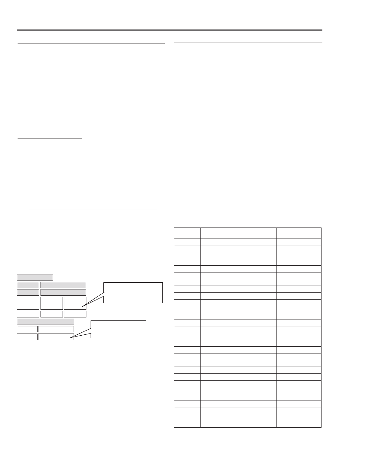
Service mode
Input Input 1
Image Standard
Group No. Data
930 0 0
Ver 1.00
Gamma
Ye Auto 1
Ye Off 1
Color shading correction adjustment
.
Software
PROJECTOR SERVICE TOOL v4.20
Signal pattern 5%, 10%, 15%, 20%, 30%, 50%,
60%, 80% whole gray
Use the software to correct the color shading of the
screen. See the further information of the software instruction manual.
The color shading correction adjustment for this model
should be performed with the whole-gray patterns specified as above.
Corresponding to the pull-down menu of the gray level
selector on the software.
Level L1 : 5%
Level L2 : 10%
Level L3 : 15%
Level L4 : 20%
Level L5 : 30%
Level L6 : 50%
Level L7 : 60%
Level L8 : 80%
Relation of level (%) indication and signal pattern
0% : Black
100% : White
0: not done
1: done
9: on calculating
1st digit: Ye Auto
10th digit: Ye Off
0: not done or failure
1: done
* Ye Auto: Advanced color Auto
White balance adjustment
⁄0
Input mode Adjusted input mode (for checking)
Signal pattern 16-step gray scale
Advanced color Auto and Off
1. Enter the service mode.
2. Select Group and No. of white balance adjustment
items referring to the table below. For example, when
adjusting the white balance in the Standard PC mode
with Advanced color : Auto, select Group - No. "982
- 11 (X value)" or "982 - 12 (Y value)".
3. Change the Data value.
4. Select Group "980", No. "0". When the Data value
is changed "0" to "10", the adjustment is performed
automatically. The Data value is returned from 10 to 0
after finishing the adjustment. It takes for 2-3 minutes
to complete the adjustment.
5. Check proper white balance and gray scale are obtained in the selected input mode.
6. Select Group "930", if the value of each lamp mode is
set "1" as shown in the figure below, the white balance
adjustment is performed correctly, if "0", adjustment is
not done or failed. Readjust again.
Group-No.
982 - 1 Advanced color-Auto: PC Dynamic -X 305
982 - 2 Advanced color-Auto: PC Dynamic -Y 325
982 - 11 Advanced color-Auto: PC Standard -X 310
982 - 12 Advanced color-Auto: PC Standard -Y 335
982 - 21 Advanced color-Auto: PC Real -X 315
982 - 22 Advanced color-Auto : PC Real -Y 340
982 - 31 Advanced color-Auto: AV Dynamic -X 305
982 - 32 Advanced color-Auto : AV Dynamic -Y 325
982 - 41 Advanced color-Auto: AV Standard -X 313
982 - 42 Advanced color-Auto : AV Standard -Y 329
982 - 51 Advanced color-Auto: AV Natural -X 313
982 - 52 Advanced color-Auto : AV Natural -Y 329
982 - 61 Advanced color-Auto: AV Cinema -X 314
982 - 62 Advanced color-Auto : AV Cinema -Y 351
983 - 1 Advanced c olor-Off: PC Dynamic -X 285
983 - 2 Advanced color-Off: PC Dynamic -Y 315
983 - 11 Advanced color-Of f: PC Standard -X 290
983 - 12 Advanced color-Of f: PC Standard -Y 315
983 - 21 Advanced color-Of f: PC Real -X 313
983 - 22 Advanced color-O ff: PC Real -Y 329
983 - 31 Advanced color-Of f: AV Dynamic -X 285
983 - 32 Advanced color-O ff: AV Dynamic -Y 315
983 - 41 Advanced color-Of f: AV Standard -X 290
983 - 42 Advanced color-Off: AV Standard -Y 315
983 - 51 Advanced color-Of f: AV Natural -X 313
983 - 52 Advanced color-O ff: AV Natural -Y 329
983 - 61 Advanced color-Of f: AV Cinema -X 314
983 - 62 Advanced color-Off: AV Cinema -Y 351
-44-
Advanced color mode:
Input Adjustment Mode (X, Y)
Data (Initial value)
LHD700 Service Manual
020-000423-02 Rev.1 (01-2013)
Page 47

Electrical Adjustment
⁄1 Wind sensor calibration
1. Enter the service mode.
2. Select Group “240” and No. “2”. Confirm the Data
value is “1”.
0: Wind sensor function Disable
1: Wind sensor function Enable
3. Select Group “240” and No. “0”.
4. To start the adjustment, change the Data value from
“0” to “1”. After the auto-calibration completed, "OK"
will appear on the screen.
IMPORTANT
Before taking this adjustment, you need to replace the
air filter with new one or scroll up the filter sheet and
make sure that the cabinet, filter unit or projection lens is
securely installed.
LHD700 Service Manual
020-000423-02 Rev.1 (01-2013)
-45-
Page 48
Electrical Adjustment
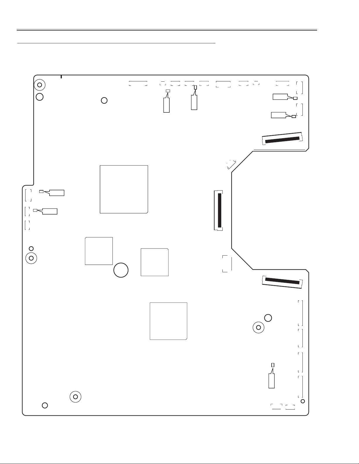
K8H
K8J
K8K
K8L
K8X
K78A
K35B
K8E
K8N
K35R
K78F
K78G
K8C
K8D
K8M
K78B
K8B
K78Z
K78H
K78C
K78D
K78E
K35G
K25Y
K8P
IC401
IC2301
IC3401
IC301
TPFN1
TPFN3
TPFN4
TPFN2
TPFN7
TPFN5
TPFN6
Test Points and Locations
MAIN BOARD
-46-
LHD700 Service Manual
020-000423-02 Rev.1 (01-2013)
Page 49

Electrical Adjustment
Service Adjustment Data Table
These initial values are the reference data written from the
CPU ROM to memory IC when replaced new memory IC. The
adjustment items indicated with “✻” are required to readjust following to the “Electrical adjustments”. Other items should be
used with the initial data value.
Grp / No. Item Functi on Range Initia l Note
0 AD Converter ( PW392)
3 ADC G-G AIN
4 ADC R-GA IN
5 ADC B-G AIN
10 S OGTH RGB/ COMPONEN T / SCART 0 - 15 2 / 4 / 4
11 S OGHYSDIS RGB/ COMPONENT / SCART 0 - 1 1 / 1 / 0
12 H S1TH H S ync1 Threshold RGB/COMPO NENT / SCART 0 - 7 4 / 4 / 4
13 H S0TH H S ync0 Thre shold RGB /COMPONEN T / SCART 0 - 7 4 / 4 / 4
10 AD C onverter ( ISL51002/ISL98 001)
3 ADC G-G AIN
4 ADC R-GA IN
5 ADC B-G AIN
20 Vi deo Deco der
0 Y Level
1 C Level
10 XCXL Pa rameter XCXL Level 0 - 4 2
11 S ync Amp Low Min imum sync am plitude t hreshold for HLOCK 1 to 0 tran sition 0 - 9 999 1792
12 S ync Amp High Minimum syn c amplitude thresho ld for HLOCK 0 to 1 t ransitio n 0 - 9999 4096
13 L uma Setup Ena ble 7.5IRE Mod e (NTSC on ly) 0 - 1 0
14 A nti-Ali as Filter A nti-Alias Filter 0 - 7 4
15 A nti-Ali as Downsam ple A nti-Alia s Downsample 0 - 3 0
16 A nti-Ali as High Frequ ency Anti-Alias Hig h Frequency 0 - 3 3
Comb 3D Cr oss-Lum a Top/Bo ttom
20
Amplit ude
PC/ YCbCr 480i ( 575i) / YCbCr 4 80p (575 p) / YCbCr 720p
(720p5 0) / YCbCr 1080 i (1035i, 1080i 50) / SCART
PC/ YCbCr 480i ( 575i) / YCbCr 4 80p (575 p) / YCbCr 720p
(720p5 0) / YCbCr 1080 i (1035i, 1080i 50) / SCART
PC/ YCbCr 480i ( 575i) / YCbCr 4 80p (575 p) / YCbCr 720p
(720p5 0) / YCbCr 1080 i (1035i, 1080i 50) / SCART
PC/ YCbCr 480i (575i) / YCbCr 480p (575p)/YCb Cr 720p(720p50)
/ YCrCb 1080 i(1035i, 108 0i50)
PC/ YCbCr 480i (575i) / YCbCr 480p (575p)/YCb Cr 720p(720p50)
/ YCrCb 1080 i(1035i, 108 0i50)
PC/ YCbCr 480i (575i) / YCbCr 480p (575p)/YCb Cr 720p(720p50)
/ YCrCb 1080 i(1035i, 108 0i50)
Composite 60Hz / S-Video 60Hz/ Com posite 50 Hz / S-Video
50Hz- Y Level ( ADC RGB Gain )
Composite 60Hz / S-Video 60Hz / C omposite 50Hz / S-Vide o
50Hz - C Level ( ADC Saturat ion)
for PAL/ SECAM only 0 - 3 3
0 - 1023 315/160 /165/170/170/30 5
0 - 1023 315/170 /175/175/175/ 305
0 - 1023 315/170/190 /185/185/3 05
0 - 1023 260/125 /130/125 /125
0 - 1023 255/125 /130/125 /125
0 - 1023 255/140 /150/140 /140
0 - 1023 153 /153/161/161
0 - 1023 410/410/440/ 440
30 HDMI (SII9127A)
100 Equalizer Manual M ode (DVI ) 0 : Fixed, 1: Ma nual Effec tice only R GB( Digital /AV HDCP) mode 0 - 1 0
101 Equalizer Manual D ata (DVI) Manu al Settin g Effecti ce only RGB (Digital /AV HDCP) mode 0 - 14 0
110 Equalizer Manual M ode (HD MI) 0: Fi xed, 1: Manua l Effecti ce only HDM I mode 0 - 1 0
111 Equalizer Manual D ata (HDM I) Manual S etting Ef fectice o nly HDMI mo de 0 - 14 0
40 General
0 IP Mode S et at IP OFF 0: Not used IP Blo ck 1: Used IP Bl ock and IP OFF 0 - 1 1
1 3:2 PullDown Mo de bit0: Glo bal Motion bit1: Video M otion 1 - 3 1
2 Detect Fi lm Mode Enable 0: 2: 3pull down & 2: 2pull dow n 1: 2:3pull down 2 : 2:2pull down 0 - 2 0
3 NR Enable fo r Analog YUV
4 NR Enable fo r Digital Y UV 0 - 1 0
41 Deinterlac er settin g Progres sive Mode1, Film Para meter Gr1/Gr2/ Gr3
0 Motion Ad aptive Weig ht Value <KDEINT> 0 - 255 30/ 30/ 30
1 Angle Int erpolation Level 0 : Conservative <= === > 4 : Aggress ive 0 - 4 4/4 /4
2 CUE Low Pass Fi lter Enable < CUELPFEN> 0 - 1 0 /0/ 0
42 Deinterlac er settin g Progres sive Mode2 Pa rameter
0 Motion Ad aptive Weig ht Value <KDEINT> 0 - 255 0/ 0/0
1 Angle Int erpolation Level 0 : Conservative <= === > 4 : Aggress ive 0 - 4 2 /2 /2
2 CUE Low Pass Fi lter Enable < CUELPFEN> 0 - 1 0 /0/ 0
47 N oise Reduc tion (time) NR L1 Paramete r
0 Noise Pixe l Range < NSRANG EY> / <NSR ANGEUV> 0 - 2 1
1 Noise Region 0 <N SREGIONY0 > / <NSREGIONUV0 > 0 - 1023 12
2 Noise Region 1 <N SREGIONY1> / < NSREGION UV1> 0 - 1023 24
3 Noise Region 2 <N SREGIONY2 > / <NSREG IONUV2> 0 - 1023 40
LHD700 Service Manual
0 : Noise Re ductio n detected w ith Y and UV mot ion 1 : Noise
Reduc tion detec ted with Y motion
-47-
0 - 1 1
Gr1:C ompsite/ S-video
Gr2: Componet /Scart /PC
Gr3: H DMI
020-000423-02 Rev.1 (01-2013)
Page 50

Electrical Adjustment
Grp / No. Item Functi on Range I nitial Note
4 Noise Gain Level < NSFILTERY**> / < NSFILTERUV** > 0 - 255 100
49 N oise Reduc tion (time) NR L 2 Parameter
0 Noise Pixe l Range < NSRANG EY> / <NSR ANGEUV> 0 - 2 1
1 Noise Region 0 <N SREGIONY0 > / <NSREGIONUV0 > 0 - 1023 12
2 Noise Region 1 <N SREGIONY1> / < NSREGION UV1> 0 - 1023 24
3 Noise Region 2 <N SREGIONY2 > / <NSREG IONUV2> 0 - 1023 40
4 Noise Gain Level < NSFILTERY**> / < NSFILTERUV** > 0 - 255 100
50 2 :2pul l down sett ing
0 22Film Mo de Sensit ivity Film Dete ction Sensitivit y <FILM STVT22 > 1 - 5 4
1 22Film Mo de Thresh old Low < FILMTHRD22A > 0 - 1023 80
2 22Film Mo de Thresh old High <FI LMTHRD22 B> 0 - 1023 120
3 Video Mo tion Wind ow Start X <VOFSTARX> 0 - 255 10
4 Video Mo tion Wind ow Stop X <VOFSTOPX > 0 - 255 10
5 Video Mo tion Wind ow Start Y <VOFSTARY> 0 - 255 10
6 Video Mo tion Wind ow Stop Y <VOFSTOPY> 0 - 255 10
51 2 :3pul l down sett ing
0 Global M otion Sensitivit y Film Dete ction Sen sitivit y <FILM STVT23 > 1 - 5 4
1 Video Mo tion Sensitivity Fi lm Detecti on Sensit ivity <VOFS TVT> 1 - 5 4
2 Video Mo tion Thres hold Low <VOFT HRDA> 0 - 1023 120
3 Video Mo tion Thres hold High <VOFTHRDB > 0 - 1023 180
4 Global M otion 23Fi lm Thresho ld <FIL MTHRD23 > 0 - 1023 100
5 Global M otion Win dow Start X <GMDSTARX > 0 - 255 10
6 Global M otion Win dow Stop X <GM DSTOPX> 0 - 255 10
7 Global M otion Win dow Start Y <GMDSTARY> 0 - 255 10
8 Global M otion Win dow Stop Y <GM DSTOPY> 0 - 255 10
55 LTI / CTI
0 Video Enh ancement E nable VEHEN 0 - 1 1
1 DLTI Gain DLTIGAIN 0 - 15 3
2 DLTI Frequency DLTIFREQ 0 - 3 2
3 Bypass A nti-Alia s Filter DTIBYPASSAAL 0 - 1 0
4 Lower DCTI Freq uency LOWERDC TIFREQ 0 - 1 1
5 DCTI Gain DCTIGAIN 0 - 15 4
6 DCTI Freque ncy D CTIFREQ 0 - 3 0
7 Color Sh ift Limit COLORSHIF TLMT 0 - 3 3
60 Sub Image
0 Center Co ntrast
1 Center Br ightness 0 - 1023
2 Center Co lor 0 - 1023
3 Center Tint 0 - 180 90 /90/ 90/ 90/9 0/ 90/ 90 /90/ 90/90 /90
4 Fixed Shar pness (Up Sca ling) 0-37 5/5 /5/ 5/5/ 5/ 5/5 /5/5 /5
5 Fixed Shar pness (Down Sc aling) 0-37 8/8/ 8/8 /8/ 8/ 8/ 8/8 /8/ 8
6 Center Sharpness (No FPG A) 0-37 16/16 /16/16/16 /16/ 16 /16/16 /16/16
7 Center WB Re d 0 - 1023
8 Center WB Gr een 0 - 1023
9 Center WB B lue 0 - 1023
10 C enter BB Red 0 - 1023
11 C enter BB Gre en 0 - 1023
12 C enter BB Blu e 0 - 1023
13 A lpha Cont rast 0 - 1000 60 /60/ 60/ 60/60 /60/ 6 0/60/ 60/ 60/60
14 A lpha Brig htness 0 - 100 0 90 /90/ 90/ 90/90 /90/ 9 0/ 90/ 90/ 90/9 0
15 A lpha Color 0 - 1000
16 A lpha Tint 0 - 1000 10/10/10 /10/10 /10/ 10/10 /10/10 /10
17 A lpha Shar pness 0 - 1000 10/10/10/10/10 /10/ 10 /10/10 /10/10
18 A lpha WB Red 0 - 1000 40/40/ 40/ 40/4 0/4 0/ 40 /40 /40/ 40/ 40
19 A lpha WB Gre en 0 - 1000 40/40/ 40/ 40/4 0/4 0/ 40 /40 /40/ 40/ 40
20 A lpha WB Blu e 0 - 1000 40/40/ 40/ 40/4 0/4 0/ 40 /40 /40/ 40/ 40
21 A lpha BB Red 0 - 1000 20 /20/ 20/ 20/ 20/ 20/ 20 /20/ 20/ 20/ 20
Group
Composite / S-Vide o / Compone nt / Digital / D-RGB-Vide o
/Anal ogRGB / RGB -Video / HDCP- PC /HDC P-AV /SCART/ PJNet
Value = (Menu Value - Menu Center) x Alph a / 10 + Center
(Effe ctive Rang e)
Contra st [Max] 1023 [Mi n] 0
Bright ness [M ax] 1023 [ Min] 0
Color [ Max] 1023 [ Min] 0
Tint [ Max] 180 [ Min] 0
Sharpn ess [Ma x] 57 [M in] 0 (Du mmy)
WB R/ G/ B [Max ] 1023 [Min] 0
BB R/ G/B [M ax] 1023 [ Min] 0
Fixed Sha rpness Up /Down [M ax] 37 [M in] 0
0 - 1023
534 /534 /578 /492 /492 /534 /
534 /492/ 492/ 534 /492
512/512/ 512/512/512/4 96
496 /512/512/ 496/ 512
512/512/ 512/512/512/ 512
/512/ 512/512/512/ 512
512/512/ 512/512/512/ 512
/512/ 512/512/512/ 512
512/512/ 512/512/512/ 512
/512/ 512/512/512/ 512
512/512/ 512/512/512/ 512
/512/ 512/512/512/ 512
512/512/ 512/512/512/ 512
/512/ 512/512/512/ 512
512/512/ 512/512/512/ 512
/512/ 512/512/512/ 512
512/512/ 512/512/512/ 512
/512/ 512/512/512/ 512
140/140 /140/140 /140/140
/140/140 /140/140 /140
-48-
LHD700 Service Manual
020-000423-02 Rev.1 (01-2013)
Page 51

Electrical Adjustment
Grp / No. Item Functi on Range I nitial Note
22 A lpha BB Gre en 0 - 1000 20/ 20/ 20/ 20/ 20/ 20/ 20 /20 /20/2 0/2 0
23 A lpha BB Blue 0 - 100 0 20 /20 /20 /20 /20 /20 / 20/ 20/ 20/ 20/ 20
80 FI NE FPGA-Set ting
0 UV DLT 0 - 31 3
1 UV Gain 0 - 2047 1030
2 UV SFT 0 - 32767 6180
3 Demo On /Of f Dem mode On/ Off 1: Dis play, 0: No dis play 0 - 1 0
4 Demo Mod e Mode 0: Demo 0, 1: Demo1 0 - 7 0
5 Area Big Ch g A rea Id 0 - 4095 67
6 Area Smal l Chg Area Id 0 - 40 95 67
7 Area Chg Se ns Ar ea Id 0 - 4095 150
8 Show Mod e Test Mod e 0: Norm al, 1: SHW1, 2:SHW2, 3:Test 0 - 3 0
9 AI_Calc _Mode AI Calcuration 0 - 2 2
230 DATA_SHIF T 0 - 7 4
232 DOT_CKSW 0 - 1 0
81 FI NE FPGA-Co lor Manage ment
0 YRange 0 - 32 8
1 HueRang e 0 - 20 10
2 GainRan ge 0 - 50 30
3 GM_M inSlope Gamma M ini Slope x 10 0 0 - 10 3
4 GM_M axSlop e Gamma Max Sl ope x 10 10 - 30 18
5 GM_Co nverge Gamma Converg e x 10 1 - 5 3
6 Not used
7 Not used
8 COLM_G ET_KIND_Y_ud No. of Ac quire Point s 1 - 9 9
9 Not used
10 N ot used
11 S ameHue 1 - 10 3
12 C ut_UVNo rm 0 - 64 5
13 C ur_MinY 0 - 127 0
14 C ur_MaxY 128 - 255 255
15 S ame_Y 0 - 63 24
16 C onv_Y 0 - 127 64
17 W B_Limi t 0 0 - 255 4
18 W B_Limi t 1 0 - 255 40
19 W B_Limi t 2 0 - 255 41
20 W B_Limi t 3 0 - 255 41
21 W B_Limi t 4 0 - 255 41
22 W B_Limi t 8 0 - 255 41
23 W B_Limi t In 0 - 255 14
24 W B_Limi t Out 0 - 255 20
25 W B_Limi t PtFlg 0 - 1 1
82 FPGA - Ye Overlay TYPE-L TYPE-R Panel Type
0 DEC_R Ye Overlay Con trol: R Co efficient(- ) 0 - 255 130 170
1 DEC_G Ye Overl ay Control : G Coeffi cient (-) 0 - 255 30 10
2 B_RATIO Ye Overlay Co ntrol: B C oeffici ent(+) 0 - 255 15 15
3 SAT_SLOPE Ye Overlay Contro l: Coef ficient (Satur ation) 0 - 255 71
4 R_SLOPE Ye Overl ay Control : Coeffi cient(R-tint ) 0 - 255 16
5 G_SLOPE Ye Overlay Control: Co effici ent(G -tint) 0 - 255 16
6 LUM_M AX Ye Overlay Cont rol: Coe fficien t(Max) PC-D ynamic 0 - 255 25 5 255
7 LUM_M AX Ye Overlay Cont rol: Coe fficien t(Max) PC-St andard 0 - 25 5 255 255
8 LUM_M AX Ye Overlay Cont rol: Coe fficien t(Max) PC-Re al 0 - 255 255 255
9 LUM_M AX Ye Overlay Cont rol: Coe fficien t(Max) AV-Dynami c 0 - 255 255 25 5
10 LU M_MA X Ye Overlay Contro l: Coef ficient (Ma x) AV-Standard 0 - 255 2 55 255
11 LU M_MA X Ye Overlay Contro l: Coef ficient (Ma x) AV-Natural 0 - 255 25 5 255
12 LU M_MA X Ye Overlay Contro l: Coef ficient (Ma x) AV-Cinema 0 - 255 255 25 5
13 LU M_MIN Ye Overlay Con trol: Co efficie nt(M in) PC-D ynamic 0 - 255 0 0
14 LU M_MIN Ye Overlay Con trol: Co efficie nt(M in) PC-S tandard 0 - 255 0 0
15 LU M_MIN Ye Overlay Con trol: Co efficie nt(M in) PC-R eal 0 - 255 0 0
16 LU M_MIN Ye Overlay Con trol: Co efficie nt(M in) AV-Dynamic 0 - 255 0 0
17 LU M_MIN Ye Overlay Con trol: Co efficie nt(M in) AV-Standard 0 - 255 0 0
18 LU M_MIN Ye Overlay Con trol: Co efficie nt(M in) AV-Natura l 0 - 255 0 0
19 LU M_MIN Ye Overlay Con trol: Co efficie nt(M in) AV-Cinem a 0 - 25 5 0 0
20 Y E_SENS Ye Overlay Co ntrol: T ime Const ant 0 - 255 4
21 Y E_TESTFLG Ye Overl ay Control : Test Flag 0 - 255 3
22 DAC _MAX Not used 0 - 255 255
23 DAC _MIN Not use d 0 - 255 0
LHD700 Service Manual
-49-
T he value is i
*
ized wh en the p anel
type is s witched.
020-000423-02 Rev.1 (01-2013)
ni tia l-
Page 52

Electrical Adjustment
Grp / No. Item Functi on Range I nitial Note
24 DAC _UseMin DAC Level at Power ON 0 - 255 0
25 Y E_FIX_VAL Ye Overlay Con trol: Ma nual value at F ix PC-Dyn amic 0 - 255 60
26 Y E_FIX_VAL Ye Overlay Con trol: Ma nual value at F ix PC-Sta ndard 0 - 255 60
27 Y E_FIX_VAL Ye Overlay Con trol: Ma nual value at F ix PC-Real 0 - 255 60
28 Y E_FIX_VAL Ye Overlay Con trol: Ma nual value at F ix AV-Dynamic 0 - 255 60
29 Y E_FIX_VAL Ye Overlay Con trol: Ma nual value at F ix AV-Standard 0 - 255 60
30 Y E_FIX_VAL Ye Overlay Con trol: Ma nual value at F ix AV-Natural 0 - 25 5 60
31 Y E_FIX_VAL Ye Overlay Con trol: Ma nual value at F ix AV-Cinema 0 - 255 60
32 DAC _RangeM ax DAC Range Max. 0 - 255 255
33 DAC _RangeM in DAC Rang e Min. 0 - 255 32
34 P_PWM _WIDTH Pane l PWM: Output Widt h 0 - 16383 600
35 DAC _LEVEL(Y EAUTO_YE_LVL) DAC Level Forced S etting (Ye Auto) 0 - 255 255
36 Y E_APLUsed APL Used R ate(%) at YE_VAL=100% 0 - 255 20
37 Y E_APLOf f APL M ax(%) at Y E_VAL= 0% 0 - 255 0
38 Y E_FIX_VAL_ SW Ye Overlay Con trol: Ma nual value Select at Fix P C-Dynam ic 0 - 1 1
39 Y E_FIX_VAL_ SW Ye Overlay Con trol: Ma nual value Select at Fix P C-Stand ard 0 - 1 1
40 Y E_FIX_VAL_ SW Ye Overlay Con trol: Ma nual value Select at Fix P C-Real 0 - 1 1
41 Y E_FIX_VAL_ SW Ye Overlay Con trol: Ma nual value Select at Fix AV-Dy namic 0 - 1 1
42 Y E_FIX_VAL_ SW Ye Overlay Con trol: Ma nual value Select at Fix AV-St andard 0 - 1 1
43 Y E_FIX_VAL_ SW Ye Overlay Con trol: Ma nual value Select at Fix AV-Na tural 0 - 1 1
44 Y E_FIX_VAL_ SW Ye Overlay Con trol: Ma nual value Select at Fix AV-Ci nema 0 - 1 1
45 Y E_APL _A0 Min : X-Cordinate at Point 0 (%) 0 - 127 30
46 Y E_APL _A1 Min : X-Cordinate at Point 1(% ) 0 - 127 62
47 Y E_APL _A2 Min : X-Cordinate at Point 2 (%) 0 - 127 75
48 Y E_APL _A3 Min : X-Cordinate at Point 3 (%) 0 - 127 90
49 Y E_APL _A4 Min : X-Cordinate at Point 4 (%) 0 - 127 100
50 Y E_GAIN_ A0 M in: Y-Cordi nate at Point 0 (%) -256 - 255 -2 0
51 Y E_GAIN_ A1 Min : Y-Cordinat e at Point 1(%) -256 - 255 -12
52 Y E_GAIN_ A2 M in: Y-Cordi nate at Point 2 (%) -256 - 255 -4
53 Y E_GAIN_ A3 M in: Y-Cordi nate at Point 3 (%) -256 - 255 13
54 Y E_GAIN_ A4 M in: Y-Cordi nate at Point 4 (%) -256 - 255 30
55 Y E_APL _B0 Max : X-Cordi nate at Point 0 (%) 0 - 127 8
56 Y E_APL _B1 Max : X-Cordi nate at Point 1( %) 0 - 127 19
57 Y E_APL _B2 Max : X-Cordi nate at Point 2 (%) 0 - 127 30
58 Y E_APL _B3 Max : X-Cordi nate at Point 3 (%) 0 - 127 38
59 Y E_APL _B4 Max : X-Cordi nate at Point 4 (%) 0 - 127 45
60 Y E_GAIN_ B0 Max : Y-Cordinate at Point 0( %) -256 - 255 20
61 Y E_GAIN_ B1 Max : Y-Cordinate at Point 1(%) -25 6 - 255 26
62 Y E_GAIN_ B2 Max : Y-Cordinate at Point 2(% ) -256 - 255 43
63 Y E_GAIN_ B3 Max : Y-Cordinate at Point 3( %) -256 - 255 70
64 Y E_GAIN_ B4 Max : Y-Cordinate at Point 4(% ) -256 - 255 100
65 Y E_APL _C0 Detect C oeffici ent: X-Cordinate at Poi nt 0(%) 0 - 127 7
66 Y E_APL _C1 Detect C oeffici ent: X-Cordinate at Poi nt 1(%) 0 - 127 25
67 Y E_APL _C2 Detect C oeffici ent: X-Cordinate at Poi nt 2(%) 0 - 127 40
68 Y E_APL _C3 Detect C oeffici ent: X-Cordinate at Poi nt 3(%) 0 - 127 50
69 Y E_APL _C4 Detect C oeffici ent: X-Cordinate at Poi nt 4(%) 0 - 127 60
70 Y E_EXP_C0 Detect Coeffi cient: Y-Cordinate at Po int 0(% ) 0 - 511 300
71 Y E_EXP_C1 Detect Coeffi cient: Y-Cordinate at Po int 1(%) 0 - 511 278
72 Y E_EXP_C2 Detect Coeffi cient: Y-Cordinate at Po int 2(%) 0 - 511 207
73 Y E_EXP_C3 Detect Coeffi cient: Y-Cordinate at Po int 3(%) 0 - 511 120
74 Y E_EXP_C4 Detect Coeffi cient: Y-Cordinate at Po int 4(%) 0 - 511 100
75 Y EOFF_YE_SW
76 Y EOFF_YE_LVL Force d DAC Level Set for Ye Off 0 - 255 255
77 C OLOR_ AJY_YEAUTO_PC Color Adj Leve l (For Ye Auto PC) 0 - 16383 100 100
78 C OLOR_ AJY_YEAUTO_AV Color Ad j Level (For Ye Auto AV) 0 - 163 83 100 100
79 C OLOR_ AJY_YEOFF_PC Co lor Adj Level ( For Ye Off PC) 0 - 16383 128 128
80 C OLOR_ AJY_YEOFF_AV Color A dj Level (For Ye Of f AV) 0 - 16383 128 128
81 Ye_Ca lc_Mo de 0: Not u se AI-SENS, 1: U se AI-SENS 0 - 1 0
82 DAT_YEBG_OFFOT 0 : On, 1: Off 0 - 1 0
83 Y E_MIN _VAL Ye value at Off-M in 0 - 255 0
Data Sel ect at Ye Off
0: Fixed :YEOFF_YE_LVL, 1:DAC Calc R esult: g _ans_ fixval
0 - 1 1
83 FI NE FPGA Sharp ness 0 - 127 0
0 Sharpness MIN [P C-SD] 0 - 127 0
1 Sharpness MIN [P C-HD] 0 - 127 0
2 Sharpness MIN [AV-SD ] 0 - 127 0
3 Sharpness MIN [AV-HD ] 0 - 127 0
4 Sharpness CENTER [ PC-SD] 0 - 127 3 5
5 Sharpness CENTER [ PC-HD ] 0 - 127 3 0
6 Sharpness CENTER [AV-SD ] 0 - 127 46
-50-
LHD700 Service Manual
020-000423-02 Rev.1 (01-2013)
Page 53

Electrical Adjustment
Grp / No. Item Functi on Range I nitial Note
7 Sharpness CENTER [AV-HD ] 0 - 127 3 5
8 Sharpness MAX [ PC-SD] 0 - 127 100
9 Sharpness MAX [ PC-HD ] 0 - 127 100
10 S harpnes s MAX [AV-SD] 0 - 127 77
11 S harpnes s MAX [AV-SD] 0 - 127 70
84 FI NE FPGA - Blending
0: Ble nding Mod e (NORM AL) 4 overlay off
0 BKMOD
1: Bland ing Mode ( BLANKI NG) 4 overlay o ff
2: Blending Mod e (NORMAL) 4 overlay on
0 - 3 3
3: Ble nding Mod e (BLA NKING) 4 overlay on
1 BLD_I_ SIZE_H Inner Fra me H 0 - 255 2
2 BLD_I_ SIZE_V In ner Frame V 0 - 255 2
3 BLD_CURVE CU RVE 0 - 255 0
4 RGB_GAI N PC- Dynamic 0 - 511 256
5 RGB_GAI N PC- Standard 0 - 511 256
6 RGB_GAI N PC- Real 0 - 511 256
7 RGB_GAI N AV-Dyna mic 0 - 511 256
8 RGB_GAI N AV-Standard 0 - 511 256
9 RGB_GAI N AV-Natur al 0 - 511 256
10 R GB_GAIN AV-Cinema 0 - 511 256
11 B ld_Exp_Int PC-Dynami c 0 - 255 64
12 B ld_Exp_Int PC-Standard 0 - 25 5 125
13 B ld_Exp_Int PC-Real 0 - 255 128
14 B ld_Exp_Int AV-Dynamic 0 - 255 128
15 B ld_Exp_Int AV-Stand ard 0 - 255 128
16 B ld_Exp_Int AV-Natur al 0 - 255 128
17 B ld_Exp_Int AV-Cine ma 0 - 255 128
18 B ld_of f_mult PC- Dynamic 0 - 255 64
19 B ld_of f_mult PC- Standard 0 - 255 64
20 B ld_of f_mult PC- Real 0 - 2 55 6 4
21 B ld_of f_mult AV-Dynam ic 0 - 255 6 4
22 B ld_of f_mult AV-Stand ard 0 - 255 64
23 B ld_of f_mult AV-Natur al 0 - 255 64
24 B ld_of f_mult AV-Cine ma 0 - 255 64
25 B LD_N_ DT_NO 0 - 15 15
26 M ultiImg Color PC-Dynamic 0 - 47 15
27 M ultiImg Color PC-Stan dard 0 - 47 15
28 M ultiImg Color PC-Real 0 - 47 15
29 M ultiImg Color AV-Dynamic 0 - 47 15
30 M ultiImg Color AV-Standard 0 - 47 15
31 M ultiImg Color AV-Natural 0 - 47 15
32 M ultiImg Color AV-Cinema 0 - 47 15
33 C caImgC olor PC- Dynamic 0 - 47 15
34 C caImgC olor PC- Standard 0 - 47 15
35 C caImgC olor PC- Real 0 - 47 15
36 C caImgC olor AV-Dynamic 0 - 47 15
37 C caImgC olor AV-Stand ard 0 - 47 15
38 C caImgC olor AV-Natur al 0 - 47 15
39 C caImgC olor AV-Cine ma 0 - 47 15
85 B lending of fset
0 BLD_4OFFSETDM 0 - 3 0
1 BLD_LT_OFFSETR
2 BLD_LT_OFFSETG
3 BLD_LT_OFFSETB
4 BLD_RT_OFFS ETR
5 BLD_RT_OFFS ETG
6 BLD_RT_OFFS ETB
7 BLD_UP_OFFSETR
8 BLD_UP_OFFSETG
9 BLD_UP_OFFSETB
10 B LD_DN_ OFFSETR
11 B LD_DN_ OFFSETG
12 B LD_DN_ OFFSETB
-32768 - 3 2676
-32768 - 3 2676
-32768 - 3 2676
-32768 - 3 2676
-32768 - 3 2676
-32768 - 3 2676
-32768 - 3 2676
-32768 - 3 2676
-32768 - 3 2676
-32768 - 3 2676
-32768 - 3 2676
-32768 - 3 2676
89 C olor Match ing - Tagrget Data
0 Target Red Dynami c-X 0 - 1000 655
1 Target Red Dynami c-Y 0 - 1000 340
2 Target Red Standard-X 0 - 1000 655
3 Target Red Standard-Y 0 - 1000 340
LHD700 Service Manual
-51-
020-000423-02 Rev.1 (01-2013)
0
0
0
0
0
0
0
0
0
0
0
0
Page 54

Electrical Adjustment
Grp / No. Item Functi on Range I nitial Note
4 Target Red Real /Natu ral-X 0 - 10 00 6 55
5 Target Red Real /Natu ral-Y 0 - 10 00 3 40
6 Target Red Cinema-X 0 - 1000 655
7 Target Red Cinema-Y 0 - 1000 340
20 Target Green D ynamic-X 0 - 1000 325
21 Target Green D ynamic-Y 0 - 1000 630
22 Target Green S tandard -X 0 - 100 0 325
23 Target Green S tandard -Y 0 - 100 0 63 0
24 Target Green R eal/ Natural -X 0 - 1000 310
25 Target Green R eal/ Natural -Y 0 - 1000 370
26 Target Green C inema-X 0 - 1000 310
27 Target Green C inema-Y 0 - 1000 670
40 Target Blue Dynami c-X 0 - 1000 150
41 Target Blue Dynami c-Y 0 - 1000 85
42 Target Blue Standard-X 0 - 1000 150
43 Target Blue Standard-Y 0 - 1000 85
44 Target Blue Real /Natu ral-X 0 - 10 00 150
45 Target Blue Real /Natu ral-Y 0 - 10 00 85
46 Target Blue Cinema-X 0 - 1000 150
47 Target Blue Cinema-Y 0 - 1000 85
60 Target White Dyna mic-X 0 - 1000 302
61 Target White Dyna mic-Y 0 - 1000 349
62 Target White Stan dard-X 0 - 1000 305
63 Target White Stan dard-Y 0 - 1000 335
64 Target White Real /Natural -X 0 - 1000 310
65 Target White Real /Natural -Y 0 - 1000 330
66 Target White Cine ma-X 0 - 100 0 314
67 Target White Cine ma-Y 0 - 100 0 3 51
100 Tagrget Da ta Update Update the adjusted targ et data when t he value is set t o 10. 0 -10 -
90 SW- FPGA
0 LVDS_ADJ _PHASE 0 - 255 32
1 TSEL 0 - 3 0
2 RST OFF 0 - 1 0
100 CLK _SHIFT_STATUS - - Read only
100 CX A7010
0 G SIG Center 0 - 127 107
1 B SIG Center 0 - 127 107
2 R SIG Center 0 - 127 107
3 G Bright C ontrol 0 - 255 0
4 B Bright C ontrol 0 - 255 0
5 R Bright C ontrol 0 - 255 0
6 G Gain Cont rol 0 - 255 208
7 B Gain Cont rol 0 - 255 208
8 R Gain Cont rol 0 - 2 55 208
9 G VCOM Contr ol 0 - 255 123
10 B VC OM Control 0 - 255 123
11 R VC OM Control 0 - 255 123
12 G S ID Control A 0 - 255 15
13 B S ID Control A 0 - 2 55 15
14 R S ID Control A 0 - 255 15
15 G S ID Control B 0 - 255 15
16 B S ID Control B 0 - 2 55 15
17 R S ID Control B 0 - 255 15
18 G S ID Control C 0 - 25 5 152
19 B S ID Control C 0 - 255 152
20 R S ID Control C 0 - 255 152
21 G S ID Control D 0 - 25 5 0
22 B S ID Control D 0 - 255 0
23 R S ID Control D 0 - 255 0
24 G S ID Control E 0 - 255 0
25 B S ID Control E 0 - 2 55 0
26 R S ID Control E 0 - 255 0
27 G S ID Control F 0 - 255 0
28 B S ID Control F 0 - 255 0
29 R S ID Control F 0 - 2 55 0
30 G S IGFRINV 0 - 255 0
31 B S IGFRINV 0 - 255 1
32 R S IGFRINV 0 - 25 5 1
-52-
LHD700 Service Manual
020-000423-02 Rev.1 (01-2013)
Page 55

Electrical Adjustment
Grp / No. Item Functi on Range I nitial Note
33 G S ID1FRINV 0 - 255 0
34 R S ID1FRINV 0 - 2 55 1
35 B S ID1FRINV 0 - 255 1
36 G S ID2FRINV 0 - 255 0
37 R S ID2FRINV 0 - 2 55 1
38 B S ID2FRINV 0 - 255 1
101 CXD2550_TG
0 SHP_R 0 - 127 30
1 SHP_G 0 - 127 30
2 SHP_B 0 - 127 3 0
3 SCANM 0 - 3 2
4 FRPM 0 or 2 0 / 2 2 * C ommon volt age adj.
5 HST_R_P C 0 - 127 7
6 HST_G_PC 0 - 127 7
7 HST_B_PC 0 - 127 7
8 HST_R_PF 0 - 127 12
9 HST_G_PF 0 - 127 12
10 H ST_B_PF 0 - 127 12
11 D CK1_R_W 0 - 255 10
12 D CK1_R_F 0 - 127 24
13 D CK2_R _W 0 - 25 5 10
14 D CK2_R _F 0 - 127 24
15 D CK3_R _W 0 - 255 10
16 D CK3_R _F 0 - 127 0
17 D CK4_R_W 0 - 255 10
18 D CK4_R_ F 0 - 127 0
19 D CK1_G_W 0 - 255 10
20 D CK1_G_F 0 - 127 24
21 D CK2_G _W 0 - 255 10
22 D CK2_G _F 0 - 127 24
23 D CK3_G_W 0 - 255 10
24 D CK3_G_ F 0 - 127 0
25 D CK4_G_W 0 - 255 10
26 D CK4_G_F 0 - 127 0
27 D CK1_B_W 0 - 25 5 10
28 D CK1_B_F 0 - 127 24
29 D CK2_B_W 0 - 255 10
30 D CK2_B_F 0 - 127 24
31 D CK3_B _W 0 - 255 10
32 D CK3_B _F 0 - 127 0
33 D CK4_B_W 0 - 25 5 10
34 D CK4_B_ F 0 - 127 0
102 CXD3550_GA M
0 GAM_ON 0 - 1 1
103 CXD3550_LO CK
0 LOCK_O N 0 - 1 1
104 CXD255_USC1
0 USC1_GAIN_ R 0 - 1023 512
1 USC1_GAIN_G 0 - 1023 512
2 USC1_GAIN_ B 0 - 1023 512
3 USC1_BRIG HT_R 0 - 8191 0
4 USC1_BRIG HT_G 0 - 8191 0
5 USC1_BRIG HT_B 0 - 8191 0
6 USC2_GAI N_R 0 - 1023 512
7 USC2_GAI N_G 0 - 1023 512
8 USC2_GAI N_B 0 - 1023 512
9 USC2_B RIGHT_R 0 - 8191 0
10 U SC2_BRIGHT_G 0 - 8191 0
11 U SC2_BRIGHT_B 0 - 8191 0
105 CXD2550_WEC
0 SVCJD_WEC_ON 0 - 1 1
1 SVCJD_WEC_R A_DWN 0 - 1 0
2 SVCJD_WEC_GA _DWN 0 - 1 0
3 SVCJD_WEC_ BA_DWN 0 - 1 0
4 SVCJD_WEC_R A_RGT 0 - 1 0 / 1
LHD700 Service Manual
-53-
020-000423-02 Rev.1 (01-2013)
Page 56

Electrical Adjustment
Grp / No. Item Functi on Range I nitial Note
5 SVCJD_WEC_GA _RGT Type L / Type R 0 - 1 0 / 1
6 SVCJD_WEC_ BA_RGT 0 - 1 0 / 1
7 SVCJD_WEC_R B_DWN 0 - 1 1
8 SVCJD_WEC_GB _DWN 0 - 1 1
9 SVCJD_WEC_ BB_DWN 0 - 1 1
10 SVC JD_WEC_RB _RGT 0 - 1 1 / 0
11 SVC JD_WEC_GB_ RGT Type L / Type R 0 - 1 1 / 0
12 SVC JD_WEC_BB _RGT 0 - 1 1 / 0
106 CXD3550_VXT
0 VXT_ON 0 - 1 1
1 VXT_LDAT1 0 - 25 5 64
2 VXT_LDAT2 0 - 25 5 85
3 VXT_LDAT3 0 - 25 5 96
4 VXT_LDAT4 0 - 25 5 128
5 VXT_LDAT5 0 - 25 5 160
6 VXT_LDAT12_H 0 - 255 6
7 VXT_LDAT12_L 0 - 255 24
8 VXT_LDAT23_ H 0 - 2 55 11
9 VXT_LDAT23_ L 0 - 255 162
10 V XT_LDAT34_H 0 - 2 55 4
11 V XT_LDAT34_L 0 - 255 0
12 V XT_LDAT45_H 0 - 2 55 4
13 V XT_LDAT45_L 0 - 255 0
14 V XT_RDATU1 0 - 255 32
15 V XT_RDATU2 0 - 255 23
16 V XT_RDATU3 0 - 255 24
17 V XT_RDATU4 0 - 255 30
18 V XT_RDATU5 0 - 255 22
19 V XT_RDATL1 0 - 255 16
20 V XT_RDATL2 0 - 255 11
21 V XT_RDATL3 0 - 255 12
22 V XT_RDATL4 0 - 255 12
23 V XT_RDATL5 0 - 255 11
24 V XT_GDATU1 0 - 255 32
25 V XT_GDATU2 0 - 255 23
26 V XT_GDATU3 0 - 255 24
27 V XT_GDATU4 0 - 255 30
28 V XT_GDATU5 0 - 255 22
29 V XT_GDATL1 0 - 255 16
30 V XT_GDATL2 0 - 255 11
31 V XT_GDATL3 0 - 255 12
32 V XT_GDATL4 0 - 255 12
33 V XT_GDATL5 0 - 255 11
34 V XT_BDATU1 0 - 255 32
35 V XT_BDATU2 0 - 255 23
36 V XT_BDATU3 0 - 255 24
37 V XT_BDATU4 0 - 255 30
38 V XT_BDATU5 0 - 255 22
39 V XT_BDATL1 0 - 255 16
40 V XT_BDATL2 0 - 255 11
41 V XT_BDATL3 0 - 255 12
42 V XT_BDATL4 0 - 255 12
43 V XT_BDATL5 0 - 255 11
44 V XT_TH_ON 0 - 15 15
45 V XT_TH1 0 - 255 0
46 V XT_TH2 0 - 255 96
47 V XT_TH3 0 - 255 187
48 V XT_TH4 0 - 255 255
107 CXD3550_S HAD
0 SHAD_ON 0 - 1 1
1 SHAD_LDAT1 0 - 255 53
2 SHAD_LDAT2 0 - 2 55 106
3 SHAD_LDAT3 0 - 2 55 160
4 SHAD_LDAT12_H 0 - 255 2
5 SHAD_LDAT12_L 0 - 255 160
6 SHAD_LDAT23_H 0 - 255 2
7 SHAD_LDAT23_L 0 - 255 94
8 SHAD_R _DAT1 0 - 255 19
-54-
LHD700 Service Manual
020-000423-02 Rev.1 (01-2013)
Page 57

Electrical Adjustment
Grp / No. Item Functi on Range I nitial Note
9 SHAD_R _DAT2 0 - 255 31
10 S HAD_R_ DAT3 0 - 255 31
11 S HAD_G_ DAT1 0 - 255 19
12 S HAD_G_ DAT2 0 - 255 31
13 S HAD_G_ DAT3 0 - 255 31
14 S HAD_B_ DAT1 0 - 255 19
15 S HAD_B_ DAT2 0 - 255 31
16 S HAD_B_ DAT3 0 - 255 31
108 CXD3550_SYC
0 SYC_MASKON 0 - 15 0
1 SYC_VSMAX 0 - 8191 148 0
109 CXD3550_F MD
0 FMD_VTFREE TH2 0 - 8191 1470
1 FMD_TLOCKT H2 0 - 8191 1465
110 CXD3540_CS C
0 CSC_XH 0 - 1 0
1 CSC_ON 0 - 1 1
2 CSC_R _GP1 0 - 511 324
3 CSC_R _GP2 0 - 511 305
4 CSC_R _GP3 0 - 511 282
5 CSC_R _GP4 0 - 511 259
6 CSC_R _GP5 0 - 511 219
7 CSC_R _GP6 0 - 511 198
8 CSC_R _GP7 0 - 511 172
9 CSC_R _GP8 0 - 511 141
10 C SC_G_GP1 0 - 511 331
11 C SC_G_GP2 0 - 511 309
12 C SC_G_GP3 0 - 511 287
13 C SC_G_GP4 0 - 511 265
14 C SC_G_GP5 0 - 511 231
15 C SC_G_GP6 0 - 511 213
16 C SC_G_GP7 0 - 511 193
17 C SC_G_GP8 0 - 511 166
18 C SC_B_G P1 0 - 511 346
19 C SC_B_G P2 0 - 511 316
20 C SC_B_G P3 0 - 511 290
21 C SC_B_G P4 0 - 511 268
22 C SC_B_G P5 0 - 511 231
23 C SC_B_G P6 0 - 511 209
24 C SC_B_G P7 0 - 511 184
25 C SC_B_G P8 0 - 511 161
200 O ption
0 Logo Dis play Prohib ition 0: Menu 1:Force d 0 - 1 0
1 RS232C Bau drate 0: 1920 0bps 1: 96 00bps 0 - 1 0
4 CABLE SW Long Ca ble 0: Di sable 1: Enab le 0 - 1 0
5 PW Debug Co mmand Enab le
6 Device Re fresh Disa ble 0: Enabl e 1: Disable 0 - 1 0
8 PJ-NET Hung up check 0: Enable 1: D isable 0 - 1 0
11 H DCP EDID Set ting
15 L ENS SHIFT SE TTING Memorize Le ns Positio n as Center whe n the value is s et to 10. 0 -10 0
21 L amp Warnin g Time (NO RMAL) 1-16 4
22 L amp Warnin g Time (ECO ) 1-16 6
23 L amp Warnin g Time (HI GH) not s upport ed 1-16
50 L amp Repla cement Di splay 1:On 0 :Off 0 - 1 1
51 F ilter Warning Display 1:On 0 :Off 0 - 1 1
52 L amp Count er Reset Time s mot supported 0 - 255 0
53 F ilter Coun ter Reset Tim es Read o nly 0 - 255 0
54 Fa ctory Default Execu te Times Read onl y 0 - 255 0
55 M otor Oper ation Stop 0 : Enable 1: Di sable 0 - 1 0
58 L amp Go Out Lam p goes out 0 - 1 0
63 S ource Sear ch Enable 0: Disabl e 1: Enable 0 - 1 1
64 I nput Searc h Skip Enbl e 0 : Disable 1: Enable 0 - 1 1
LHD700 Service Manual
0: Dis able (Sa nyo Serial Co mmand Enabl e)
1: Enable ( PW Debug M ode)
0: Patt ern1
1: Pattern 2
2: Patte rn3
3: Patt ern4
4: Pattern5
0 - 1 0
0 - 4 0
-55-
020-000423-02 Rev.1 (01-2013)
Page 58

Electrical Adjustment
Grp / No. Item Functi on Range I nitial Note
70 A DC Device Se lect for An alog PC 0 = ISL51002, 1 = PW3 92 AFE 0 - 1 0
71 A DC Device Se lect for Co mponent 0 = ISL 51002, 1 = PW392 AFE 0 - 1 0
72 C omponen t/R GB Auto SW 0: Dis able 1: Enab le 0 - 1 1
80 D estinat ion Langu age Set at Shipping 0: English 1:Japan ese 0 - 1 0
95 F licker 1 0: Di sable 1: Enable 0 - 1 0
96 F licker 2 0 - 15 8
100 Dis able Auto Pic ture Contr ol 0 : Nor mal operat ion 1 : Auto Pic ture Contro l Off 0 - 1 Initial : 1 Shippi ng 0
110 Mon itor Outpu t during Co oling 0 : On 1: Off 0 - 1 0
112 Mon itor Out Lin k with Vide o Mute 0 : Not link 1: Li nk 0 - 1 1
120 HDM I Cont at Stan dby 0: Not c ontrol 1: Al low to contro l 0 - 1 1
130 Log o Countdown t ime 0: 30 se c. 1: 20 sec. 0 - 1 0
140 Of fset Add Sta tus 0: N ot use Off set additi on - 0 Read only
141 Of fset Chang e App ly offset va lue when the value is set to 10. 0 - 10 0
142 Of fset Value Offset value at Shutdown te mp. - 10 Re ad only
143 Exec uted time s of Offset A dd - 0 Read only
144 Canc eled time o f Offset Ad d - 0 Read only
170 Power Mgmt Shutdow n time u nit: hou r 1 - 24 3
180 CcaTargetLi nkedChan ge "YCM" l enked func tion on Color matching Target change 0 - 1 1
201 O ption (S ignal)
0 FrameLoc k Option
1 Dither En able 0: Dis able 1: Enabl e 0 - 1 0
3 Field Sens Invert Enable 0 : Disable 1 : Enable 0 - 1 0
205 S pread Spec trum
0 Enable 0: On 1: Of f 0 - 1 1
1 Ratio 0 t o 300 0 - 300 200
2 Frequenc y 200 to 500 1 - 500 350
210 L amp Contor l
0 Dimmer SW 0:A uto 1:Man ual 0 - 1 0
1 Manual Co ntrol
19 D IMMER_ LEVEL_ AUTO Curren t Y Level (Read o nly) - - Read only
20 D IMMER_ LEVEL_ NORMAL Dim Level at Nor mal 0 - 15 15
21 D IMMER_ LEVEL_ ECO Di m Level at Eco 0 - 15 0
23 VO LTAGE_LEVEL Lamp Volt age (Read o nly) - - Read only
220 Pr ojector Err or Log
0 Warning _Log_1 La test Error lo g 0 - 32767 0
: : : : :
49 Wa rning_ Log_5 0 50t h Error log 0 - 32767 0
50 Wa rning_ Log Reset Lo g is cleared w hen the value is set to 10. 0 - 10 0
235 S hutter
0 PRE_MOT ION S hutter Warm - u p Operati on (0: Yes, 1: No ) 0 - 1 Initial: 1 / S hipping : 0
1 CMP_TRM Chat tering De tecting Term 0 - 3 2767 70 00
2 OUT_DLY_TRM O utput Term 0 - 32767 150 00
3 CMP_CHK_CNT C ount of Infor mation Sy nc 0 - 15 0
4 OPEN_D LY Open Output Delay 0 - 63 0
5 CLOSE_D LY Close Output Delay 0 - 63 0
6 Positio n Check Tim e Positi on Check Ti me 1 - 255 50
8 Enable Cl ose Cmd Shutter Cl ose Comma nd 0: Disable 1: Enabl e 0 - 1 1
9 Speed Co ntrol Shutter S peed 0 - 255 0
10 S hutter Ma nagement U pper Time Shut ter Maneme nt Time for Up per limit 180 -9 99 48 0
0: Of f for PC signa ls
1: Off for AV si gnals
3: Nor mal
4: Norm al
Lamp Power M anual Cont rol (DIM MER_CTRL _LEVEL
0( Dark)~15(B right) )
0 - 4 4
0 - 15 0
240 Flow Calibra tion
0 Flow Cali bration Ex e
1 Flow Cali bration Err or Log
2 Clog Che ck Enable Filter Clogged D etection by Flow Sensor (0: Disable, 1: Enab le) 0 - 1 Initial: 0 / Sh ipping : 1
4 Time Limi t Auto Scrol l Enable Auto Sc roll for Man imum Time ( o: Disable 1: Enable) ) 0 - 1 1
Flow Sens or Offse t Calibration Start c alibrat ion when the value
is set to 1.
Log of Cali bration Error (Read only)
255: No t Calibrat ion
0: No Err or
10: 1st Calib ration Not S table Air flow
11: 1st Calibratio n Out of Range
20: 2nd N ot Stable A irflow
21: 2nd Out of Range
100: 10th C alibrati on Not Stab le Airflow
101: 10th Calibr ation Out of R ange
0 - 1 0
- 255
-56-
Win d sensor cal ibr
*
tion.
a-
LHD700 Service Manual
020-000423-02 Rev.1 (01-2013)
Page 59

Electrical Adjustment
Grp / No. Item Functi on Range I nitial Note
5 Clog Auto C oolin Enab le Auto Cleaning at C logged ( 0: Disable 1: Eanbl e) 0 - 1 1
6 Scroll Fai l Auto Cooli ng Enable Auto C leaning at S croll Error ( 0: Disable 1: Ea nble) 0 - 1 1
7 Timer Forc e Scroll Enable Forc ed Scroll w hen Filter T imer reach ed 0 - 1 1
241 Flow Ideal Dat a (Value w ill be set af ter calibr ation)
0 Flow Idea l Data 1 Flo w Sensor The ory Value No.1 Corre spondin g to Fan Volt No.1 0 - 1023 301
1 Flow Idea l Data 2 Flo w Sensor The ory Value No. 2 Corresp onding to Fan Vol t No.2 0 - 1023 343
2 Flow Idea l Data 3 Flo w Sensor The ory Value No.3 Correspo nding to Fan Volt N o.3 0 - 1023 380
3 Flow Idea l Data 4 Flo w Sensor The ory Value No.4 C orrespon ding to Fan Volt No.4 0 - 1023 400
4 Flow Idea l Data 5 Flo w Sensor The ory Value No. 5 Correspo nding to Fan Volt N o.5 0 - 1023 410
5 Flow Idea l Data 6 Flo w Sensor The ory Value No.6 C orrespo nding to Fan Volt N o.6 0 - 1023 1023
6 Flow Idea l Data 7 Flo w Sensor The ory Value No.7 Co rresponding to Fan Volt No.7 0 - 1023 1023
7 Flow Idea l Data 8 Flo w Sensor The ory Value No.8 Correspo nding to Fan Volt N o.8 0 - 1023 1023
242 Flow Calib. Fan Volt (Not Memorized)
0 Flow Cali b Fan Volt 1 Flow Se nsor Calib ration Fan Volt age No.1 [x10 V] 0 - 255 50
1 Flow Cali b Fan Volt 2 Flow Se nsor Calib ration Fan Volt age No.2 [x10 V ] 0 - 255 70
2 Flow Cali b Fan Volt 3 Flow Se nsor Calib ration Fan Volt age No.3 [x10 V] 0 - 255 95
3 Flow Cali b Fan Volt 4 Flow Se nsor Calib ration Fan Volt age No.4 [x10 V] 0 - 255 120
4 Flow Cali b Fan Volt 5 Flow Se nsor Calib ration Fan Volt age No.5 [x10 V] 0 - 255 138
5 Flow Cali b Fan Volt 6 Flow Se nsor Calib ration Fan Volt age No.6 [x10 V] 0 - 255 255
6 Flow Cali b Fan Volt 7 Flow Se nsor Calib ration Fan Volt age No.7 [x10 V] 0 - 255 255
7 Flow Cali b Fan Volt 8 Flow Se nsor Calib ration Fan Volt age No.8 [x10 V] 0 - 255 255
243 Flow Calib Eff ective Difference (N ot Memoriz ed)
0 Flow Cali b Effective Diff 1 Flow S ensor Cali bration Ra nge Diff N o.1 [ADC] 0 - 1023 180
1 Flow Cali b Effective Diff 2 Flow S ensor Cali bration Ra nge Diff N o.2 [ADC ] 0 - 1023 180
2 Flow Cali b Effective Diff 3 Flow S ensor Cali bration Ra nge Diff N o.3 [ADC] 0 - 1023 180
3 Flow Cali b Effective Diff 4 Flow S ensor Cali bration Ra nge Diff N o.4 [ADC] 0 - 1023 180
4 Flow Cali b Effective Diff 5 Flow S ensor Cali bration Ra nge Diff N o.5 [ADC] 0 - 1023 180
5 Flow Cali b Effective Diff 6 Flow S ensor Cali bration Ra nge Diff N o.6 [ADC] 0 - 1023 1023
6 Flow Cali b Effective Diff 7 Flow S ensor Cali bration Ra nge Diff N o.7 [ADC] 0 - 1023 1023
7 Flow Cali b Effective Diff 8 Flow S ensor Cali bration Ra nge Diff N o.8 [ADC] 0 - 1023 1023
244 Flow Clog Thre shold (N ot Memorize d )
0 Flow Clog T hreshold 1 Fl ow Sensor Cl ogged Thr eshold No.1[A DC] 0 - 1023 40
1 Flow Clog T hreshold 2 Fl ow Sensor Cl ogged Thr eshold No. 2[ADC] 0 - 1023 46
2 Flow Clog T hreshold 3 Fl ow Sensor Cl ogged Thr eshold No. 3[AD C] 0 - 1023 56
3 Flow Clog T hreshold 4 Fl ow Sensor Cl ogged Thr eshold No.4 [ADC] 0 - 102 3 77
4 Flow Clog T hreshold 5 Fl ow Sensor Cl ogged Thr eshold No. 5[AD C] 0 - 1023 84
5 Flow Clog T hreshold 6 Fl ow Sensor Cl ogged Thr eshold No.6[AD C] 0 - 1023 1023
6 Flow Clog T hreshold 7 Fl ow Sensor Cl ogged Thr eshold No.7 [ADC] 0 - 1023 1023
7 Flow Clog T hreshold 8 Fl ow Sensor Cl ogged Thr eshold No. 8[AD C] 0 - 1023 1023
245 Filter Roll
0 Take Up Bend Remove Filter Flexure Star ts when the Val ue is set to 1. 0 - 1 0
1 Take Up Times Remaining T imes of Filte r Scroll ( Read only) - -
2 Take Up Time Reset
3 Scroll C ounter Rese t Time Scrol l Counter Reset Times ( Read only) 0 - 255 -
4 Scroll Informatio n Cartri dge No 0 - 2 0
246 Flow Clog Mon itor ( Read only)
0 Real Flow Da ta Real Fl ow Data [ADC ] (Read o nly) 0 - 1023 -
1 Ideal Flow Data The ory Flow Data (Read on ly) 0 - 1023 -
2 Flow Dif ference Dat a Flow Differenc e Data [ADC ] (Read only) 0 - 1023 -
3 Clog Dete ct Flow Dif ference Da ta Difference Dat a to judge th e Filter Clogged [ADC ] (Read o nly) 0 - 1023 -
4 Warn Detec t Flow Difference Data
5 Press Add Da ta Add Data by A ir Pressure ( Read only ) 0 - 1023 -
6 Filter Sc roll Timer Timer fo r Filter Scr oll [hour ] (Read on ly) 0 - 32767 -
247 Filter Scroll Time (Read only) * 999 9 means not exe cuted
Filter Sc roll Time s Reset
Resets Re maining Scroll Time s when the Value i s set to 10.
Differe nce Data to jud ge the Filter Cl ogged Warning [ADC] ( Read
only)
0 - 10 0
0 - 1023 -
LHD700 Service Manual
020-000423-02 Rev.1 (01-2013)
-57-
Page 60

Electrical Adjustment
Grp / No. Item Functi on Range I nitial Note
0 Filter 1st Car tridge S croll Tim e 1
1 Filter 1st Car tridge S croll Tim e 2 0 - 32767 9999
2 Filter 1st Car tridge S croll Tim e 3 0 - 32767 9999
3 Filter 1st Car tridge S croll Tim e 4 0 - 32767 9999
4 Filter 1st Car tridge S croll Tim e 5 0 - 32767 9999
5 Filter 1st Car tridge S croll Tim e 6 0 - 32767 9999
6 Filter 1st Car tridge S croll Tim e 7 0 - 32767 9999
7 Filter 1st Car tridge S croll Tim e 8 0 - 32767 9999
8 Filter 1st Car tridge S croll Tim e 9 0 - 32767 9999
9 Filter 1st Car tridge S croll Tim e 10 0 - 32767 9999
10 F ilter 2nd Car tridge S croll Tim e 1
11 F ilter 2nd Car tridge S croll Tim e 2 0 - 32767 9999
12 F ilter 2nd Car tridge S croll Tim e 3 0 - 32767 9999
13 F ilter 2nd Car tridge S croll Tim e 4 0 - 32767 9999
14 F ilter 2nd Car tridge S croll Tim e 5 0 - 32767 9999
15 F ilter 2nd Car tridge S croll Tim e 6 0 - 32767 9999
16 F ilter 2nd Car tridge S croll Tim e 7 0 - 32767 9999
17 F ilter 2nd Car tridge S croll Tim e 8 0 - 32767 9999
18 F ilter 2nd Car tridge S croll Tim e 9 0 - 32767 9999
19 F ilter 2nd Car tridge S croll Tim e 10 0 - 32767 9999
20 F ilter 3rd Cartridg e Scroll Ti me 1
21 F ilter 3rd Cartridg e Scroll Ti me 2 0 - 32767 9999
22 F ilter 3rd Cartridg e Scroll Ti me 3 0 - 32767 9999
23 F ilter 3rd Cartridg e Scroll Ti me 4 0 - 32767 9999
24 F ilter 3rd Cartridg e Scroll Ti me 5 0 - 32767 9999
25 F ilter 3rd Cartridg e Scroll Ti me 6 0 - 32767 9999
26 F ilter 3rd Cartridg e Scroll Ti me 7 0 - 32767 9999
27 F ilter 3rd Cartridg e Scroll Ti me 8 0 - 32767 9999
28 F ilter 3rd Cartridg e Scroll Ti me 9 0 - 32767 9999
29 F ilter 3rd Cartridg e Scroll Ti me 10 0 - 32767 9999
1st Filter Car tridge U sed time at N times Scrol ling [ho ur] (N:1-10)
2nd Filter Car tridge Us ed time at N times Sc rolling [h our] (N :1-10)
3rd Filter Cartridge Used tim e at N times Sc rolling [ hour] (N :1-10)
0 - 32767 9999
0 - 32767 9999
0 - 32767 9999
248 Filter Scroll Factor (Read only) * 255 means not executed
0 Filter 1st Car tridge S croll Facto r 1
1 Filter 1st Car tridge S croll Facto r 2 0 - 25 5 255
2 Filter 1st Car tridge S croll Facto r 3 0 - 25 5 255
3 Filter 1st Car tridge S croll Facto r 4 0 - 25 5 255
4 Filter 1st Car tridge S croll Facto r 5 0 - 25 5 255
5 Filter 1st Car tridge S croll Facto r 6 0 - 25 5 255
6 Filter 1st Car tridge S croll Facto r 7 0 - 25 5 255
7 Filter 1st Car tridge S croll Facto r 8 0 - 25 5 255
8 Filter 1st Car tridge S croll Facto r 9 0 - 25 5 255
9 Filter 1st Car tridge S croll Facto r 10 0 - 25 5 255
10 F ilter 2nd Car tridge S croll Fact or 1
11 F ilter 2nd Car tridge S croll Fact or 2 0 - 255 255
12 F ilter 2nd Car tridge S croll Fact or 3 0 - 255 255
13 F ilter 2nd Car tridge S croll Fact or 4 0 - 255 255
14 F ilter 2nd Car tridge S croll Fact or 5 0 - 255 255
15 F ilter 2nd Car tridge S croll Fact or 6 0 - 255 255
16 F ilter 2nd Car tridge S croll Fact or 7 0 - 255 255
17 F ilter 2nd Car tridge S croll Fact or 8 0 - 255 255
18 F ilter 2nd Car tridge S croll Fact or 9 0 - 255 255
Filter 2n d Cartrid ge Scroll Fa ctor
19
10
20 F ilter 3rd Cartridg e Scroll Fac tor 1
21 F ilter 3rd Cartridg e Scroll Fac tor 2 0 - 255 255
22 F ilter 3rd Cartridg e Scroll Fac tor 3 0 - 255 255
23 F ilter 3rd Cartridg e Scroll Fac tor 4 0 - 255 255
24 F ilter 3rd Cartridg e Scroll Fac tor 5 0 - 255 255
25 F ilter 3rd Cartridg e Scroll Fac tor 6 0 - 255 255
26 F ilter 3rd Cartridg e Scroll Fac tor 7 0 - 255 255
27 F ilter 3rd Cartridg e Scroll Fac tor 8 0 - 255 255
28 F ilter 3rd Cartridg e Scroll Fac tor 9 0 - 255 255
Filter 3r d Cartri dge Scrol l Factor
29
10
1st Filter Car tridge S crollin g Factor at N tim es Scrolli ng (N:1-10)
0: Man ual Scrolling with OSD Menu
1: Auto Scr olling detecting by Fi lter Clogg ed
: Auto S crolling d e
2
a sheet
2nd Filte r Cartrid ge Scroll ing Factor at N t imes Scro lling (N :1-10)
0: Man ual Scrolling with OSD Menu
1: Auto Scr olling detecting by Fi lter Clogg ed
: Auto S crolling d e
2
a sheet
3rd Filter Cartridge Scrol ling Factor at N t imes Scro lling (N :1-10)
0: Man ual Scrolling with OSD Menu
1: Auto Scr olling detecting by Fi lter Clogg ed
: Auto S crolling d e
2
a sheet
tectin g by specifi ed maxim um used time per
tectin g by specifi ed maxim um used time per
tectin g by specifi ed maxim um used time per
0 - 255 255
0 - 255 255
0 - 255 255
0 - 255 255
0 - 255 255
249 Pr essure Sen sor
0 Pressure M onitor Pre ssure Value wit h no Compen sation (A DC) - - R ead only
1 Pressure M onitor Pre ssure Value wit h Compens ation (AD C) - - R ead only
2 Press Of fset Pressure Value Offset -1023 - 1023 0
3 Press Cali b Effecti ve Diff C alibrati on Effect ive Range (AD C) 0 - 1023 160
-58-
LHD700 Service Manual
020-000423-02 Rev.1 (01-2013)
Page 61

Electrical Adjustment
Top
30°
330°
150°
210°
Bottom
Ceiling
Normal
Grp / No. Item Functi on Range I nitial Note
0: Calibration exe cuted cor rectly
4 Press Sensor Log
250 Fan Vol tage Adjustment
0 Fan 1 Min Adju st (DAC)
1 Fan 1 Max Adj ust (DAC) 0 -255 240 * Fan voltage adj .
2 Fan 2 Min Adju st (DAC) 0-2 55 20 * Fan voltag e adj.
3 Fan 2 Max Adj ust (DAC) 0 -255 2 35 * Fan voltag e adj.
4 Fan 3 Min Adju st (DAC) 0-2 55 20 * Fan voltag e adj.
5 Fan 3 Max Adj ust (DAC) 0 -255 240 * Fan voltage adj .
6 Fan 4 Min Adju st (DAC) 0-2 55 15 * Fan voltag e adj.
7 Fan 4 Max Adj ust (DAC) 0 -255 2 30 * Fan voltag e adj.
8 Fan 5 Min Adju st (DAC) 0-2 55 15 * Fan voltag e adj.
9 Fan 5 Max Adj ust (DAC) 0 -255 215 * Fan voltage adj .
10 Fa n 6 Min Adjust ( DAC) 0-25 5 15 * Fan voltage a dj.
11 Fa n 6 Max Adjus t (DAC) 0-255 215 * Fan voltage a dj.
12 Fa n 7 Min Adjust ( DAC) 0-25 5 15 * Fan voltage a dj.
13 Fa n 7 Max Adjus t (DAC) 0-255 240 * Fan voltage a dj.
252 Fan O ption
1 Safety Sw itch Safety Applicat ion use 0- 6 0
2 Fan Manual S witch Fan M anual SW (0 : Auto 1: Manual) 0-1 0
3 Fan1 Manual Voltage
4 Fan2 Manua l Voltage 0-255 100
5 Fan3,4 Manu al Voltage 0 -255 100
6 Fan5 Manua l Voltage 0-255 100
7 Fan6 Manua l Voltage 0-255 100
8 Fan7 Manual Voltage 0-255 100
9 Fan8 Manua l Voltage 0-255 100
10 A ngle Data A Angl e Data A (Rea d only) - -
11 A ngle Data B Angl e Data B (Rea d only) - -
12 Press Data Air Pres sure Data ( Read only) - -
10: Out of Range Offset Min.
20: Ou t of Range Of fset Max.
99: Ca libratio n not excuted
DAC Output fo r Fan Voltage adj .
Adjust Toler ance betwe en DAC and Fan Volt.
*Lamp M ode: Eco
Manual Ad justmen t Mode (0.1V)
*Effec tive only wh en Manual SW is 1.
- 99
0-255 20 * Fan vo ltage adj .
0-255 100
253 Fan Temp Error Settin g ( Memorize d) Normal Ceili ng Top Bottom
5 Temp A Warning ( Normal) Temp A (R oom) to judge the Temp Error at N ormal 30-100 47 47 47 47
6 Temp B Warning ( Normal) Temp B ( Lamp) to ju dge the Temp Error a t Normal 30 -100 8 0 80 80 80
7 Temp C Warning ( Normal) Temp C (Pane l) to judge t he Temp Error at Nor mal 30-100 68 68 68 68
8 Temp B-A Warnin g (Norma l) Temp B - A (Fi lter Clogg ed) to jud ge the Temp Error at No rmal 0 -100 50 50 50 5 0
9 Temp C-A Warning (Norma l) Temp C - A (Filter Clogged ) to judge t he Temp Error at Norm al 0-100 32 32 32 32
10 Temp A War ning (Ec o) Temp A (Room) to jud ge the Temp Error at Ec o 3 0-100 47 47 47 47
11 Temp B War ning (Ec o) Temp B (L amp) to jud ge the Temp Error at Ec o 30-100 80 80 80 80
12 Temp C War ning (Ec o) Temp C (Panel ) to judge the Temp Error at Eco 30-100 68 68 68 68
13 Temp B -A Warning ( Eco) Temp B - A (F ilter Clog ged) to judge the Temp Error at Eco 0-100 50 50 50 5 0
14 Temp C -A Warning ( Eco) Temp C - A (Filt er Clogge d) to judge the Temp Error at Eco 0 -100 32 32 32 3 2
15 Temp A War ning Off set (Temp)
0-100 13
16 Temp B War ning Off set (Temp) 0 -100 13
17 Temp C War ning Off set (Temp) 0-100 13
Temp Warning Of fset (Temp)
18 Temp B -A Warning O ffset (Temp) 0-100 13
19 Temp C -A Warning Of fset (Temp) 0 -100 13
20 Temp A War ning Off set (Time )
0-40 3
21 Temp B War ning Off set (Time ) 0-40 3
22 Temp C War ning Off set (Time ) 0 -40 3
Time Warning Offse t (Time)
23 Temp B -A Warning O ffset (Ti me) 0-40 3
24 Temp C -A Warning Of fset (Ti me) 0-40 3
254 Fan C ontrol Ran ge Setti ng ( Temp/S pinning ) Normal Ceilin g Top B ottom
16 N ormal Fan Co ntrol Min Temp
17 N ormal Fan Co ntrol Max Temp 20-100 3 8 38 38 38
LHD700 Service Manual
020-000423-02 Rev.1 (01-2013)
Temp Sensor Co ntrol Star t/ End Temp St Norma l
-59-
20-100 31 31 31 31
Page 62

Electrical Adjustment
Grp / No. Item Functi on Range I nitial Note
18 N ormal Fan1 Min
19 N ormal Fan1 Max 000 0-999 0 138 138 138 138
20 N ormal Fan2 M in 0000-9 990 90 9 0 115 115
21 N ormal Fan2 M ax 00 00-9 990 90 9 0 115 115
22 N ormal Fan3,4 Min 0000-999 0 70 70 70 70
23 N ormal Fan3,4 Max 0000-999 0 138 138 138 138
24 N ormal Fan5 M in 0000-9 990 95 9 5 95 95
25 N ormal Fan5 M ax 00 00-9 990 138 138 138 138
26 N ormal Fan6 M in 0000-9 990 60 6 0 60 60
27 N ormal Fan6 M ax 00 00-9 990 138 138 138 138
28 N ormal Fan7 Min 00 00-9 990 65 6 5 65 65
29 N ormal Fan7 Max 000 0-999 0 138 138 138 138
30 N ormal Fan8 M in 0000-9 990 80 8 0 80 80
31 N ormal Fan8 M ax 00 00-9 990 138 138 138 138
32 E co Fan Contro l Min Temp
33 E co Fan Contro l Max Temp 20-100 38 38 38 38
34 E co Fan1 Min
35 E co Fan1 Max 0000-9 990 110 110 110 110
36 E co Fan2 Min 00 00-99 90 138 138 138 138
37 E co Fan2 Max 0000-9 990 60 6 0 70 70
38 E co Fan3,4 Min 0000 -9990 55 55 55 55
39 E co Fan3,4 Max 000 0-99 90 138 138 138 138
40 E co Fan5 Min 00 00-99 90 75 75 75 75
41 E co Fan5 Max 0000-9 990 138 138 138 138
42 E co Fan6 Min 00 00-99 90 50 50 50 50
43 E co Fan6 Max 0000-9 990 138 138 138 138
44 E co Fan7 Min 00 00-99 90 50 50 50 50
45 E co Fan7 Max 0000-9 990 138 138 138 138
46 E co Fan8 Min 00 00-99 90 70 70 70 70
47 E co Fan8 Max 0000-9 990 138 138 138 138
Fan Spinn ing Set at Normal (Min /Max) ( 0.1V)
Temp Sensor Co ntrol Star t/ End Temp St Eco
Fan Spinn ing Set at Eco ( Min/ Max) (0.1V)
0000-999 0 120 120 120 120
20-100 31 31 31 31
0000-999 0 110 110 110 110
255 Fan S tart /Cooling Setting
0 Fan1 Initial Volt
1 Fan2 Initi al Volt 0 -255 70
2 Fan3,4 Init ial Volt 0 -255 70
3 Fan5 Initi al Volt 0 -255 70
4 Fan6 Initial Volt 0 -255 70
5 Fan7 Initial Volt 0 -255 70
6 Fan8 Initi al Volt 0 -255 70
8 Coolin g Time Cool ong Time Set ting (x3 0 sec.) 1: 30 3 : 90 15: 450 1-15 3
10 Temp Er ror Coolin g Time
11 O nStart C ooling St art Thres hold 0-100 50
12 A fter shutd own cooli ng Co oling Ope ration af ter Shut Down ( 0: No, 1: Yes) 0-1 1
13 N ormal Fan2 C ooling Voltage Coolin g Fan Voltage of Fan2 at Normal x0.1V 0 - 255 50 50 5 0 50
14 E co Fan2 Cooli ng Voltage Cooling Fan Voltage of Fan2 at Ec o x0.1V 0 - 255 50 50 50 50
259 Fan A ir Pressure S etting
0 Press Sour ce Range Low Press ure Sensor C ontrol Ran ge (AD) 0-1024 637
1 Press Sour ce Range Hi gh 0 -1024 293
2 Press Fan Add R ange High Add Volta ge (0.1V) 0 - 2000 0
3 Press Fan Add R ange Low 0 - 2000 65
4 Temp C-A Upward H igh Temp C -A Upward Hig h 0 - 1000 31
5 Temp C-A Upward Low Temp C-A Upward L ow 0 - 1000 29
6 Temp C-A Downwar d High Temp C-A Downw ard High 0 - 1000 20
7 Temp C-A Downwar d Low Temp C -A Downward Lo w 0 - 1000 16
260 Au to Calibration (Co mmon) * Auto cali bration
0 Execute C alibrati on
1 Loop Cou nt Ma x Times of Calibration 1 - 30 8
2 Auto Statu s
3 AutoWait Wai ting time 1 - 20 3
4 CHECK - Toleranc e Toleranc e of Offset 1 - 25 5 4
5 Time out wa it Wa it Time unti l Time out [sec.] 1 - 255 20
Fan Star t Voltage (0.1V)
Coolin g Time Sett ing When th e Temp Error occur s (x30 sec .)
1: 30 3: 9 0 15: 450
Execut e Calibration when the Val ue is changed. (For PC Wh ite
100%)
Calibration Log ( Read only)
0: Calibration En d Correct ly 1: On Adjus ting 9: Ca librati on
Error
0-255 70
1-15 3
0 - 1 0
0 / 1 / 9 0
261 Au to Calibration (RG B) PW392-AFE MDL <10bits >
-60-
LHD700 Service Manual
020-000423-02 Rev.1 (01-2013)
Page 63

Electrical Adjustment
Grp / No. Item Functi on Range I nitial Note
0 OFFSET ARE A H START B lack Level Ac q. Area H Star t 0 - 1000 975
1 OFFSET ARE A V START Black Level Ac q. Area V Star t 0 - 1000 500
2 GAIN AREA H START W hite Level Acq. Area H Star t 0 - 1000 25
3 GAIN AREA V START White L evel Acq. Area V S tart 0 - 1000 500
4 Image ARE A H WIDTH Bla ck/ White Level Area Width 0 - 40 95 13
5 Image ARE A V HEIGHT Bl ack/ White Level A rea Height 0 - 40 95 9
6 OFFSET Target Bla ck Level Adj tar get 0 - 102 3 20
7 OFFSET Toleran ce Bl ack Level Adj te lerance 1 - 1023 1
8 GAIN Target Whit e Level Adj targ et 0 - 102 3 9 55
9 GAIN Toleranc e White Level Ad j teleranc e 1 - 1023 1
10 I mage Level Tolerance Acq. I mage Level Adj Tolerance 1 - 255 2
262 Au to Calibration (CVBS /SVIDEO) PW3 92-AFE MDL <10bits>
0 Y Image Area Start X Y Im age Area H Start 0 - 1000 20
1 Y Image Area Start Y Y Im age Area V Start 0 - 10 00 2 00
6 Image Area H WIDTH Im age Level Acq. W idth 0 - 4095 8
7 Image Area V HEIGHT Im age Level Acq. H eight 0 - 4095 9
8 Y Target Level Y Level Adj t arget 0 - 1023 875
11 G ain Tolerance Level Adj Tolerance 1 - 255 1
12 I mage Level Tolerance Acq. I mage Level Adj Tolerance 1 - 255 2
264 Au to Calibration (YCbCr) PW392-AFE MDL <10bits >
0 Y-OFFSET ARE A H START Y - Of fset Acq Area H S tart 0 - 100 0 92 5
1 Y-OFFSET ARE A V START Y - O ffset Acq A rea V Start 0 - 1000 500
2 CB - OFFSET AR EA H START CB - Offset Ac q. Area H Star t 0 - 1000 925
3 CB - OFFSET AR EA V START CB - Offset Acq. Area V Sta rt 0 - 100 0 50 0
4 CR - OFFSET AREA H START CR - Of fset Acq. Area H Start 0 - 1000 925
5 CR - OFFSET AREA V START CR - O ffset Ac q. Area V Star t 0 - 1000 500
6 Y - GAIN AREA H START Y 0 - 1000 50
7 Y - GAIN AREA V START 0 - 1000 500
8 CB - GAIN ARE A H START 0 - 1000 800
9 CB - GAIN ARE A V START 0 - 1000 500
10 C R - GAIN AREA H START 0 - 100 0 70 0
11 C R - GAIN AREA V START 0 - 1000 500
12 I mage AREA H WI DTH YCBCR Level Ac q. Width 0 - 4095 13
13 I mage AREA V HEIGHT YCBCR Leve l Acq. Heigh t 0 - 4095 9
14 Y - O FFSET TARGET 0 - 1023 4
15 C B OFFSET TARGET 0 - 1023 512
16 C R OFFSET TARGET 0 - 1023 512
17 Y - G AIN TARGET 0 - 1023 810
18 C B - GAIN TARGET 0 - 1023 892
19 C R - GAIN TARGET 0 - 1023 892
20 O FFSET Toleranc e OFFSE T Adj Tolerance 1 - 255 1
21 G AIN Tolerance GA IN Adj Tolerance 1 - 255 1
22 I mage Level Tolerance Acq. I mage Level Adj Tolerance 1 - 255 2
280 Au toPC Adjsu t
0 AutoPCAdj ustEnabl e
1 Frequenc y Step TotalD ot Search Ste p 0-3 1
2 Frequenc y Threshol d TotalDo t Match 0 - 10 5
3 Fine Phase
4 BLKDET Black Level De tect Area 0 - 7 1
5 PHASEMSK
290 Panel Type
0 Gamma L /R View 0 - 20
1 Gamma L /R Chang e
300 Closed Capt ion
2 Multi Wi ndow Capti on Closed Ca ption Dis play at PIP 0: O ff, 1: On 0 - 1 1
500 C omposite ( NTSC) Compos ite / S-Video
1 Disp Dot s 0 - 4095 674
2 H Back Porc h 0 - 4095 24
3 V Back Porc h 0 - 40 95 18
4 Disp Lin e 0 - 4095 456
LHD700 Service Manual
Auto PC Ope ration with the un-su pporte d signal in.
0: Enab le 1: Disable
Phase af ter Total Dot Adj.
0: Fine Phase Execute 1: Fine Phas e Not Execut e
Phase Detect Filter
0: All B its Enable, 1 : Lower 1 bit Dis able
Change t he Panel Type when th e value is set to 2 0 or 0.
0: for Type L, 2 0 for Type R
-61-
0 - 1 0
0 - 1 1
0 - 3 0
1 10
020-000423-02 Rev.1 (01-2013)
0: L Type Panel
20: R Type Pane l
Read only
Page 64

Electrical Adjustment
Grp / No. Item Functi on Range I nitial Note
501 C omposite ( PAL) Com posite / S-Vi deo
1 Disp Dot s 0 - 4095 662
2 H Back Porc h 0 - 4095 32
3 V Back Porc h 0 - 40 95 20
4 Disp Lin e 0 - 4095 538
502 C omposite ( SECAM) Compo site / S-Vide o
1 Disp Dot s 0 - 4095 662
2 H Back Porc h 0 - 4095 32
3 V Back Porc h 0 - 40 95 20
4 Disp Lin e 0 - 4095 538
510 SCART(480i )
0 Total Dots 0 - 4095 858
1 Disp Dot s 0 - 4095 672
2 H Back Porc h 0 - 4095 142
3 V Back Porc h 0 - 40 95 42
4 Disp Lin e 0 - 4095 458
5 Clamp 0 - 40 95 59
6 Clamp Width 0 - 4095 20
511 SCART (575i)
0 Total Dots 0 - 4095 862
1 Disp Dot s 0 - 4095 656
2 H Back Porc h 0 - 4095 158
3 V Back Porc h 0 - 40 95 60
4 Disp Lin e 0 - 4095 536
5 Clamp 0 - 40 95 68
6 Clamp Width 0 - 4095 20
520 YCb Cr (480i )
0 Total Dots 0 - 4095 858
1 Disp Dot s 0 - 4095 672
2 H Back Porc h 0 - 4095 143
3 V Back Porc h 0 - 40 95 48
4 Disp Lin e 0 - 4095 456
5 Clamp 0 - 40 95 10
6 Clamp Width 0 - 4095 31
22 ( SUB) H Ba ck Porch 0 - 409 5 145
23 ( SUB) V Ba ck Porch 0 - 4 095 4 4
25 ( SUB) Cl amp 0 - 4 095 9 2
26 ( SUB) Cl amp Width 0 - 4095 2 0
521 YCb Cr (575i)
0 Total Dots 0 - 4095 864
1 Disp Dot s 0 - 4095 664
2 H Back Porc h 0 - 4095 156
3 V Back Porc h 0 - 40 95 60
4 Disp Lin e 0 - 4095 542
5 Clamp 0 - 40 95 10
6 Clamp Width 0 - 4095 31
22 ( SUB) H Ba ck Porch 0 - 409 5 158
23 ( SUB) V Ba ck Porch 0 - 4 095 5 8
25 ( SUB) Cl amp 0 - 4 095 9 8
26 ( SUB) Cl amp Width 0 - 4095 2 0
522 YCb Cr (480P)
0 Total Dots 0 - 4095 1716
1 Disp Dot s 0 - 4095 1368
2 H Back Porc h 0 - 4095 274
3 V Back Porc h 0 - 40 95 46
4 Disp Lin e 0 - 4095 458
5 Clamp 0 - 40 95 10
6 Clamp Width 0 - 4095 31
22 ( SUB) H Ba ck Porch 0 - 409 5 280
23 ( SUB) V Ba ck Porch 0 - 4 095 4 6
25 ( SUB) Cl amp 0 - 4 095 188
26 ( SUB) Cl amp Width 0 - 4095 2 0
-62-
LHD700 Service Manual
020-000423-02 Rev.1 (01-2013)
Page 65

Electrical Adjustment
Grp / No. Item Functi on Range I nitial Note
523 YCb Cr (575P)
0 Total Dots 0 - 4095 1728
1 Disp Dot s 0 - 4095 1380
2 H Back Porc h 0 - 4095 284
3 V Back Porc h 0 - 40 95 54
4 Disp Lin e 0 - 4095 552
5 Clamp 0 - 40 95 10
6 Clamp Width 0 - 4095 31
22 ( SUB) H Ba ck Porch 0 - 409 5 294
23 ( SUB) V Ba ck Porch 0 - 4 095 5 4
25 ( SUB) Cl amp 0 - 4 095 198
26 ( SUB) Cl amp Width 0 - 4095 2 0
524 YCb Cr (720P - 60 )
0 Total Dots 0 - 4095 1650
1 Disp Dot s 0 - 4095 1248
2 H Back Porc h 0 - 4095 308
3 V Back Porc h 0 - 40 95 34
4 Disp Lin e 0 - 4095 700
5 Clamp 0 - 40 95 110
6 Clamp Width 0 - 4095 31
22 ( SUB) H Ba ck Porch 0 - 409 5 316
23 ( SUB) V Ba ck Porch 0 - 4 095 3 4
25 ( SUB) Cl amp 0 - 4 095 187
26 ( SUB) Cl amp Width 0 - 4095 2 0
525 YCb Cr (720P - 50 )
0 Total Dots 0 - 4095 1980
1 Disp Dot s 0 - 4095 1248
2 H Back Porc h 0 - 4095 306
3 V Back Porc h 0 - 40 95 34
4 Disp Lin e 0 - 4095 700
5 Clamp 0 - 40 95 110
6 Clamp Width 0 - 4095 31
22 ( SUB) H Ba ck Porch 0 - 409 5 314
23 ( SUB) V Ba ck Porch 0 - 4 095 3 4
25 ( SUB) Cl amp 0 - 4 095 183
26 ( SUB) Cl amp Width 0 - 4095 2 0
526 YCb Cr (1080i - 60 )
0 Total Dots 0 - 4095 2 200
1 Disp Dot s 0 - 4095 1874
2 H Back Porc h 0 - 4095 250
3 V Back Porc h 0 - 40 95 54
4 Disp Lin e 0 - 4095 1050
5 Clamp 0 - 40 95 80
6 Clamp Width 0 - 4095 31
22 ( SUB) H Ba ck Porch 0 - 409 5 258
23 ( SUB) V Ba ck Porch 0 - 4 095 5 2
25 ( SUB) Cl amp 0 - 4 095 168
26 ( SUB) Cl amp Width 0 - 4095 2 0
527 YCb Cr (1080i - 50 )
0 Total Dots 0 - 4095 2640
1 Disp Dot s 0 - 4095 1872
2 H Back Porc h 0 - 4095 252
3 V Back Porc h 0 - 40 95 52
4 Disp Lin e 0 - 4095 1052
5 Clamp 0 - 40 95 80
6 Clamp Width 0 - 4095 31
22 ( SUB) H Ba ck Porch 0 - 409 5 258
23 ( SUB) V Ba ck Porch 0 - 4 095 5 0
25 ( SUB) Cl amp 0 - 4 095 168
26 ( SUB) Cl amp Width 0 - 4095 2 0
528 YCb Cr (1035i)
0 Total Dots 0 - 4095 2 200
1 Disp Dot s 0 - 4095 1874
2 H Back Porc h 0 - 4095 252
3 V Back Porc h 0 - 40 95 92
LHD700 Service Manual
020-000423-02 Rev.1 (01-2013)
-63-
Page 66

Electrical Adjustment
Grp / No. Item Functi on Range I nitial Note
4 Disp Lin e 0 - 4095 1006
5 Clamp 0 - 40 95 80
6 Clamp Width 0 - 4095 31
22 ( SUB) H Ba ck Porch 0 - 409 5 258
23 ( SUB) V Ba ck Porch 0 - 4 095 9 0
25 ( SUB) Cl amp 0 - 4 095 168
26 ( SUB) Cl amp Width 0 - 4095 2 0
529 YCb Cr (1080P-60)
0 Total Dots 0 - 4095 2 200
1 Disp Dot s 0 - 4095 1874
2 H Back Porc h 0 - 4095 236
3 V Back Porc h 0 - 40 95 52
4 Disp Lin e 0 - 4095 1052
5 Clamp 0 - 40 95 80
6 Clamp Width 0 - 4095 31
530 YCb Cr (1080P-50 )
0 Total Dots 0 - 4095 2640
1 Disp Dot s 0 - 4095 1872
2 H Back Porc h 0 - 4095 236
3 V Back Porc h 0 - 40 95 52
4 Disp Lin e 0 - 4095 1052
5 Clamp 0 - 40 95 80
6 Clamp Width 0 - 4095 31
531 YCb Cr (1080P-30 )
0 Total Dots 0 - 4095 2 200
1 Disp Dot s 0 - 4095 1872
2 H Back Porc h 0 - 4095 250
3 V Back Porc h 0 - 40 95 54
4 Disp Lin e 0 - 4095 1050
5 Clamp 0 - 40 95 80
6 Clamp Width 0 - 4095 31
532 YCb Cr (1080P-25)
0 Total Dots 0 - 4095 2640
1 Disp Dot s 0 - 4095 1872
2 H Back Porc h 0 - 4095 252
3 V Back Porc h 0 - 40 95 54
4 Disp Lin e 0 - 4095 1052
5 Clamp 0 - 40 95 80
6 Clamp Width 0 - 4095 31
533 YCb Cr (1080P-24)
0 Total Dots 0 - 4095 2750
1 Disp Dot s 0 - 4095 1874
2 H Back Porc h 0 - 4095 248
3 V Back Porc h 0 - 40 95 54
4 Disp Lin e 0 - 4095 1052
5 Clamp 0 - 40 95 80
6 Clamp Width 0 - 4095 31
534 YCb Cr (1080PSF-3 0) * Not s elected i n System
535 YCb Cr (1080PSF-25 ) * Not s elected i n System
536 YCb Cr (1080PSF-24)
0 Total Dots 0 - 4095 2750
1 Disp Dot s 0 - 4095 1878
2 H Back Porc h 0 - 4095 248
3 V Back Porc h 0 - 40 95 50
4 Disp Lin e 0 - 4095 1052
5 Clamp 0 - 40 95 80
6 Clamp Width 0 - 4095 31
540 RGB Video (4 80i)
0 Total Dots 0 - 4095 1716
1 Disp Dot s 0 - 4095 1424
2 H Back Porc h 0 - 4095 282
-64-
LHD700 Service Manual
020-000423-02 Rev.1 (01-2013)
Page 67

Electrical Adjustment
Grp / No. Item Functi on Range I nitial Note
3 V Back Porc h 0 - 40 95 38
4 Disp Lin e 0 - 4095 486
5 Clamp 0 - 40 95 80
6 Clamp Width 0 - 4095 31
22 ( SUB) H Ba ck Porch 0 - 409 5 288
23 ( SUB) V Ba ck Porch 0 - 4 095 4 0
25 ( SUB) Cl amp 0 - 4 095 150
26 ( SUB) Cl amp Width 0 - 4095 31
541 RGB Video ( 575i)
0 Total Dots 0 - 4095 1736
1 Disp Dot s 0 - 4095 1408
2 H Back Porc h 0 - 4095 318
3 V Back Porc h 0 - 40 95 44
4 Disp Lin e 0 - 4095 576
5 Clamp 0 - 40 95 80
6 Clamp Width 0 - 4095 20
22 ( SUB) H Ba ck Porch 0 - 409 5 320
23 ( SUB) V Ba ck Porch 0 - 4 095 4 4
25 ( SUB) Cl amp 0 - 4 095 160
26 ( SUB) Cl amp Width 0 - 4095 31
542 RGB Video (4 80P)
0 Total Dots 0 - 4095 1716
1 Disp Dot s 0 - 4095 1424
2 H Back Porc h 0 - 4095 246
3 V Back Porc h 0 - 40 95 42
4 Disp Lin e 0 - 4095 484
5 Clamp 0 - 40 95 70
6 Clamp Width 0 - 4095 20
22 ( SUB) H Ba ck Porch 0 - 409 5 252
23 ( SUB) V Ba ck Porch 0 - 4 095 4 2
25 ( SUB) Cl amp 0 - 4 095 170
26 ( SUB) Cl amp Width 0 - 4095 31
543 RGB Video ( 575P)
0 Total Dots 0 - 4095 1736
1 Disp Dot s 0 - 4095 1412
2 H Back Porc h 0 - 4095 268
3 V Back Porc h 0 - 40 95 50
4 Disp Lin e 0 - 4095 576
5 Clamp 0 - 40 95 70
6 Clamp Width 0 - 4095 20
22 ( SUB) H Ba ck Porch 0 - 409 5 278
23 ( SUB) V Ba ck Porch 0 - 4 095 5 0
25 ( SUB) Cl amp 0 - 4 095 170
26 ( SUB) Cl amp Width 0 - 4095 31
544 RGB Video (72 0P - 60 )
0 Total Dots 0 - 4095 1650
1 Disp Dot s 0 - 4095 1280
2 H Back Porc h 0 - 4095 294
3 V Back Porc h 0 - 40 95 26
4 Disp Lin e 0 - 4095 720
5 Clamp 0 - 40 95 110
6 Clamp Width 0 - 4095 31
22 ( SUB) H Ba ck Porch 0 - 409 5 30 0
23 ( SUB) V Ba ck Porch 0 - 4 095 2 6
25 ( SUB) Cl amp 0 - 4 095 150
26 ( SUB) Cl amp Width 0 - 4095 31
545 RGB Video (72 0P - 50 )
0 Total Dots 0 - 4095 1980
1 Disp Dot s 0 - 4095 1280
2 H Back Porc h 0 - 4095 292
3 V Back Porc h 0 - 40 95 26
4 Disp Lin e 0 - 4095 720
5 Clamp 0 - 40 95 110
6 Clamp Width 0 - 4095 31
22 ( SUB) H Ba ck Porch 0 - 409 5 296
LHD700 Service Manual
020-000423-02 Rev.1 (01-2013)
-65-
Page 68

Electrical Adjustment
Grp / No. Item Functi on Range I nitial Note
23 ( SUB) V Ba ck Porch 0 - 4 095 2 2
25 ( SUB) Cl amp 0 - 4 095 150
26 ( SUB) Cl amp Width 0 - 4095 31
546 RGB Video (1080 i - 60)
0 Total Dots 0 - 4095 2 200
1 Disp Dot s 0 - 4095 1920
2 H Back Porc h 0 - 4095 224
3 V Back Porc h 0 - 40 95 40
4 Disp Lin e 0 - 4095 1080
5 Clamp 0 - 40 95 80
6 Clamp Width 0 - 4095 31
22 ( SUB) H Ba ck Porch 0 - 409 5 234
23 ( SUB) V Ba ck Porch 0 - 4 095 4 0
25 ( SUB) Cl amp 0 - 4 095 150
26 ( SUB) Cl amp Width 0 - 4095 31
547 RGB Video (1080 i - 50)
0 Total Dots 0 - 4095 2640
1 Disp Dot s 0 - 4095 1920
2 H Back Porc h 0 - 4095 228
3 V Back Porc h 0 - 40 95 40
4 Disp Lin e 0 - 4095 1080
5 Clamp 0 - 40 95 60
6 Clamp Width 0 - 4095 10
22 ( SUB) H Ba ck Porch 0 - 409 5 236
23 ( SUB) V Ba ck Porch 0 - 4 095 4 0
25 ( SUB) Cl amp 0 - 4 095 120
26 ( SUB) Cl amp Width 0 - 4095 31
548 RGB Video (1035 i)
0 Total Dots 0 - 4095 2 200
1 Disp Dot s 0 - 4095 1920
2 H Back Porc h 0 - 4095 230
3 V Back Porc h 0 - 40 95 78
4 Disp Lin e 0 - 4095 1035
5 Clamp 0 - 40 95 80
6 Clamp Width 0 - 4095 31
22 ( SUB) H Ba ck Porch 0 - 409 5 236
23 ( SUB) V Ba ck Porch 0 - 4 095 7 8
25 ( SUB) Cl amp 0 - 4 095 150
26 ( SUB) Cl amp Width 0 - 4095 31
549 N ot used
550 N ot used
551 RGB Video (1080 P - 30)
0 Total Dots 0 - 4095 2 200
1 Disp Dot s 0 - 4095 1920
2 H Back Porc h 0 - 4095 230
3 V Back Porc h 0 - 40 95 40
4 Disp Lin e 0 - 4095 1080
5 Clamp 0 - 40 95 80
6 Clamp Width 0 - 4095 31
22 ( SUB) H Ba ck Porch 0 - 409 5 120
23 ( SUB) V Ba ck Porch 0 - 4 095 4 0
25 ( SUB) Cl amp 0 - 4 095 8 0
26 ( SUB) Cl amp Width 0 - 4095 10
552 RGB Video (1080 P - 25)
0 Total Dots 0 - 4095 2640
1 Disp Dot s 0 - 4095 1920
2 H Back Porc h 0 - 4095 230
3 V Back Porc h 0 - 40 95 40
4 Disp Lin e 0 - 4095 1080
5 Clamp 0 - 40 95 80
6 Clamp Width 0 - 4095 31
22 ( SUB) H Ba ck Porch 0 - 409 5 120
23 ( SUB) V Ba ck Porch 0 - 4 095 4 0
-66-
LHD700 Service Manual
020-000423-02 Rev.1 (01-2013)
Page 69

Electrical Adjustment
Grp / No. Item Functi on Range I nitial Note
25 ( SUB) Cl amp 0 - 4 095 8 0
26 ( SUB) Cl amp Width 0 - 4095 10
553 RGB Video (1080 P - 24)
0 Total Dots (Read o nly) 0 - 4095 2750
1 Disp Dot s 0 - 4095 1920
2 H Back Porc h 0 - 4095 228
3 V Back Porc h 0 - 40 95 40
4 Disp Lin e 0 - 4095 1080
5 Clamp 0 - 40 95 80
6 Clamp Width 0 - 4095 31
22 ( SUB) H Ba ck Porch 0 - 409 5 120
23 ( SUB) V Ba ck Porch 0 - 4 095 4 0
25 ( SUB) Cl amp 0 - 4 095 8 0
26 ( SUB) Cl amp Width 0 - 4095 10
555 RGB Video (1080 PSF - 30)
0 Total Dots (Read o nly) 0 - 4095 2200
1 Disp Dot s 0 - 4095 1920
2 H Back Porc h 0 - 4095 236
3 V Back Porc h 0 - 40 95 40
4 Disp Lin e 0 - 4095 1080
5 Clamp 0 - 40 95 80
6 Clamp Width 0 - 4095 31
22 ( SUB) H Ba ck Porch 0 - 409 5 239
23 ( SUB) V Ba ck Porch 0 - 4 095 4 0
25 ( SUB) Cl amp 0 - 4 095 150
26 ( SUB) Cl amp Width 0 - 4095 31
556 RGB Video (1080 PSF - 25)
0 Total Dots (Read o nly) 0 - 4095 2640
1 Disp Dot s 0 - 4095 1920
2 H Back Porc h 0 - 4095 236
3 V Back Porc h 0 - 40 95 40
4 Disp Lin e 0 - 4095 1080
5 Clamp 0 - 40 95 60
6 Clamp Width 0 - 4095 10
22 ( SUB) H Ba ck Porch 0 - 409 5 239
23 ( SUB) V Ba ck Porch 0 - 4 095 4 0
25 ( SUB) Cl amp 0 - 4 095 120
26 ( SUB) Cl amp Width 0 - 4095 15
557 RGB Video (1080 PSF - 24)
0 Total Dots (Read o nly) 0 - 4095 2760
1 Disp Dot s 0 - 4095 1920
2 H Back Porc h 0 - 4095 236
3 V Back Porc h 0 - 40 95 40
4 Disp Lin e 0 - 4095 1080
5 Clamp 0 - 40 95 64
6 Clamp Width 0 - 4095 31
22 ( SUB) H Ba ck Porch 0 - 409 5 236
23 ( SUB) V Ba ck Porch 0 - 4 095 4 0
25 ( SUB) Cl amp 0 - 4 095 150
26 ( SUB) Cl amp Width 0 - 4095 31
930 Au toGamma * PC White ba lance
0 GAM_CALC _STATUS
1 GAM_ MEASURE_ STATUS
Result of A uto Gamma Adjustment
0: Not Ca lculate d, 1: Calcula ted, 9: On C alculating
Unit Dig it: Resu lt at Ye Device Auto
10th Digi t: Resul t at Ye Device Off
Auto Gamm a Result
0: Not Ca lculate d, 1: Calcula ted
0 - 99 0
0 - 99 0
982 Au to Gamma Adjus tment (Ye Auto) Parameter set ting for Auto G amma Adj. * PC W hite balance
0 Ye Auto : PC Dynamic : LVL_USE x0.01 1 - 999 100
1 Ye Auto : PC Dynamic : W_SXY_0 x0.001 0 - 999 305
2 Ye Auto : PC Dynamic : W_SXY_1 x0.001 0 - 999 325
3 Ye Auto : PC Dynamic : B_SXY_0 x0.001 0 - 999 3 05
4 Ye Auto : PC Dynamic : B_SXY_1 x0.001 0 - 999 325
5 Ye Auto : PC Dynamic : F_SXY_0 x0.001 0 - 1999 0
6 Ye Auto : PC Dynamic : F_SXY_1 x0.001 0 - 1999 0
LHD700 Service Manual
-67-
020-000423-02 Rev.1 (01-2013)
Page 70

Electrical Adjustment
Grp / No. Item Functi on Range I nitial Note
Ye Auto : PC Dynami c:
7
LIMIT_CONTR AST
Ye Auto : PC Dynami c :
8
CAL_CO NT
Ye Auto : PC Dynami c :
9
CONT_USE
10 Ye Auto : PC S tandard : LVL_USE x0.01 1 - 999 95
11 Ye Auto : PC S tandard : W_ SXY_0 x0.0 01 0 - 999 310
12 Ye Auto : PC S tandard : W_ SXY_1 x0.0 01 0 - 999 3 35
13 Ye Auto : PC S tandard : B _SXY_0 x0.001 0 - 99 9 310
14 Ye Auto : PC S tandard : B _SXY_1 x0.001 0 - 99 9 335
15 Ye Auto : PC S tandard : F_SXY_0 x0.001 0 - 1999 310
16 Ye Auto : PC S tandard : F_SXY_1 x0.001 0 - 1999 33 5
Ye Auto : PC Standa rd:
17
LIMIT_CONTR AST
Ye Auto : PC Standa rd :
18
CAL_CO NT
Ye Auto : PC Standa rd :
19
CONT_USE
20 Ye Auto : PC R eal : LVL_USE x 0.01 1 - 999 82
21 Ye Auto : PC R eal : W_SXY_0 x0.001 0 - 9 99 315
22 Ye Auto : PC R eal : W_SXY_1 x0.001 0 - 9 99 34 0
23 Ye Auto : PC R eal : B_SXY_0 x0.001 0 - 99 9 315
24 Ye Auto : PC R eal : B_SXY_1 x0.001 0 - 99 9 340
25 Ye Auto : PC R eal : F_SXY_0 x0.0 01 0 - 1999 315
26 Ye Auto : PC R eal : F_SXY_1 x0. 001 0 - 1999 340
Ye Auto : PC Real:
27
LIMIT_CONTR AST
28 Ye Auto : PC R eal : CAL_CO NT RESULT CONTRAST * R ead only - -
29 Ye Auto : PC R eal : CONT_USE Used Ra te at Black Ba lance (x0.001) 100 - 5 000 750
30 Ye Auto : AV Dyn amic : LVL_USE x0. 01 1 - 999 100
31 Ye Auto : AV Dyn amic : W_SXY_0 x 0.001 0 - 999 305
32 Ye Auto : AV Dyn amic : W_SXY_1 x 0.001 0 - 999 325
33 Ye Auto : AV Dyn amic : B_SX Y_0 x0 .001 0 - 999 305
34 Ye Auto : AV Dyn amic : B_SX Y_1 x 0.001 0 - 999 325
35 Ye Auto : AV Dyn amic : F_SXY_0 x0.0 01 0 - 1999 0
36 Ye Auto : AV Dyn amic : F_SXY_1 x0.001 0 - 1999 0
Ye Auto : AV Dynamic :
37
LIMIT_CONTR AST
Ye Auto : AV Dynamic :
38
CAL_CO NT
Ye Auto : AV Dynamic :
39
CONT_USE
40 Ye Auto : AV Sta ndard : LVL_USE x0.01 1 - 999 86
41 Ye Auto : AV Sta ndard : W_SXY_0 x0.001 0 - 999 313
42 Ye Auto : AV Sta ndard : W_SXY_1 x0.001 0 - 999 329
43 Ye Auto : AV Sta ndard : B_ SXY_0 x0.0 01 0 - 999 313
44 Ye Auto : AV Sta ndard : B_ SXY_1 x0.0 01 0 - 999 3 29
45 Ye Auto : AV Sta ndard : F_SXY_0 x0.001 0 - 1999 313
46 Ye Auto : AV Sta ndard : F_SXY_1 x0.001 0 - 199 9 3 29
Ye Auto : AV Standard :
47
LIMIT_CONTR AST
Ye Auto : AV Standard :
48
CAL_CO NT
Ye Auto : AV Standard :
49
CONT_USE
50 Ye Auto : AV Nat ural : LVL_USE x0.01 1 - 999 8 0
51 Ye Auto : AV Nat ural : W_SXY_0 x0 .001 0 - 999 313
52 Ye Auto : AV Nat ural : W_SXY_1 x0 .001 0 - 999 329
53 Ye Auto : AV Nat ural : B_SX Y_0 x0.001 0 - 999 313
54 Ye Auto : AV Nat ural : B_SX Y_1 x0.001 0 - 99 9 329
55 Ye Auto : AV Nat ural : F_SXY_0 x0.001 0 - 1999 313
56 Ye Auto : AV Nat ural : F_SXY_1 x0.001 0 - 1999 329
Ye Auto : AV Natural :
57
LIMIT_CONTR AST
58 Ye Auto : AV Nat ural : CAL_CONT RES ULT CONTRAST * Read o nly - -
59 Ye Auto : AV Nat ural : CONT_USE Used Rate at Black Balanc e (x0.001) 100 - 5000 750
60 Ye Auto : AV Cin ema : LVL_USE x0 .01 1 - 999 80
61 Ye Auto : AV Cin ema : W_SXY_0 x0.001 0 - 999 314
62 Ye Auto : AV Cin ema : W_SXY_1 x0.001 0 - 999 3 51
63 Ye Auto : AV Cin ema : B_SXY_0 x0.001 0 - 99 9 314
64 Ye Auto : AV Cin ema : B_SXY_1 x0.001 0 - 99 9 351 * W hite balan ce adj.
65 Ye Auto : AV Cin ema : F_SXY_0 x0.0 01 0 - 1999 314
RESULT CONTRAST * Read only - -
Used Rate at Black Bal ance (x0.0 01) 100 - 50 00 1000
RESULT CONTRAST * Read only - -
Used Rate at Black Bal ance (x0.0 01) 100 - 50 00 1000
RESULT CONTRAST * Read only - -
Used Rate at Black Bal ance (x0.0 01) 100 - 50 00 1000
RESULT CONTRAST * Read only - -
Used Rate at Black Bal ance (x0.0 01) 100 - 50 00 80 0
100 - 5000 50 00
100 - 5000 50 00
100 - 5000 1500
100 - 5000 50 00
100 - 5000 1700
100 - 5000 1500
-68-
LHD700 Service Manual
020-000423-02 Rev.1 (01-2013)
Page 71

Electrical Adjustment
Grp / No. Item Functi on Range I nitial Note
66 Ye Auto : AV Cin ema : F_SXY_1 x0 .001 0 - 1999 351
Ye Auto : AV Cinema:
67
LIMIT_CONTR AST
68 Ye Auto : AV Cin ema : CAL_CO NT RESULT CONTRA ST * Read only - -
69 Ye Auto : AV Cin ema : CONT_USE Used R ate at Black B alance (x 0.001) 10 0 - 5000 700
983 Au to Gamma Adj ustment ( Ye Off) Paramet er settin g for Auto Gamma A dj.
0 Ye Off : PC Dynam ic : LVL_USE x0.01 1 - 999 100
1 Ye Off : PC Dynam ic : W_SXY_0 x0.001 0 - 999 285
2 Ye Off : PC Dynam ic : W_SXY_1 x0.001 0 - 999 315
3 Ye Off : PC Dynam ic : B_SXY_0 x 0.001 0 - 999 285
4 Ye Off : PC Dynam ic : B_SXY_1 x 0.001 0 - 999 315
5 Ye Off : PC Dynam ic : F_SXY_0 x0.001 0 - 1999 0
6 Ye Off : PC Dynam ic : F_SXY_1 x0.001 0 - 1999 0
Ye Off : PC Dynam ic:
7
LIMIT_CONTR AST
8 Ye Off : PC Dynam ic : CAL_CON T R ESULT CONTRAST * Rea d only - -
9 Ye Off : PC Dynam ic : CONT_USE Used Rat e at Black Balance (x0. 001) 100 - 50 00 1000
10 Ye Of f : PC Standar d : LVL_USE x0.01 1 - 999 85
11 Ye Of f : PC Standar d : W_SXY_0 x0.0 01 0 - 999 2 90
12 Ye Of f : PC Standar d : W_SXY_1 x0.0 01 0 - 999 315
13 Ye Of f : PC Standar d : B_SXY_0 x0.0 01 0 - 999 29 0
14 Ye Of f : PC Standar d : B_SXY_1 x0.0 01 0 - 999 315
15 Ye Of f : PC Standar d : F_SXY_0 x0.001 0 - 1999 290
16 Ye Of f : PC Standar d : F_SXY_1 x 0.001 0 - 1999 315
Ye Off : PC Stand ard:
17
LIMIT_CONTR AST
18 Ye Of f : PC Standar d : CAL_CONT RESU LT CONTRAST * Read on ly - -
19 Ye Of f : PC Standar d : CONT_USE Used Rate at Black Balanc e (x0.001) 100 - 5000 10 00
20 Ye Of f : PC Real : LVL_USE x0.01 1 - 999 70
21 Ye Of f : PC Real : W_SXY_0 x0.001 0 - 99 9 313
22 Ye Of f : PC Real : W_SXY_1 x0.001 0 - 99 9 329
23 Ye Of f : PC Real : B_SX Y_0 x 0.001 0 - 999 313
24 Ye Of f : PC Real : B_SX Y_1 x 0.001 0 - 999 329
25 Ye Of f : PC Real : F_SXY_0 x0.0 01 0 - 1999 313
26 Ye Of f : PC Real : F_SXY_1 x0.0 01 0 - 1999 329
Ye Off : PC Real :
27
LIMIT_CONTR AST
28 Ye Of f : PC Real : CAL_CONT RESULT CONTRAST * Read o nly - -
29 Ye Of f : PC Real : CONT_USE Used Rate at Blac k Balance ( x0.001) 100 - 5000 700
30 Ye Of f : AV Dynamic : LVL_USE x0.01 1 - 999 100
31 Ye Of f : AV Dynamic : W_SX Y_0 x0.001 0 - 999 285
32 Ye Of f : AV Dynamic : W_SX Y_1 x0.001 0 - 999 315
33 Ye Of f : AV Dynamic : B_ SXY_0 x0.001 0 - 999 285
34 Ye Of f : AV Dynamic : B_ SXY_1 x0.001 0 - 999 315
35 Ye Of f : AV Dynamic : F_SXY_0 x0.001 0 - 199 9 0
36 Ye Of f : AV Dynamic : F_SXY_1 x0.0 01 0 - 1999 0
Ye Off : AV Dynamic :
37
LIMIT_CONTR AST
38 Ye Of f : AV Dynamic : CAL _CONT RESULT CONTRAST * Read only - -
39 Ye Of f : AV Dynamic : CON T_USE Used Rate at Black Balance (x0.001) 100 - 5 000 100 0
40 Ye Of f : AV Standard : LVL_US E x0.01 1 - 999 80
41 Ye Of f : AV Standard : W_SX Y_0 x0.001 0 - 999 290
42 Ye Of f : AV Standard : W_SX Y_1 x0.001 0 - 999 315
43 Ye Of f : AV Standard : B _SXY_0 x0.001 0 - 999 290
44 Ye Of f : AV Standard : B _SXY_1 x0.001 0 - 999 315
45 Ye Of f : AV Standard : F_SXY_0 x0.001 0 - 1999 29 0
46 Ye Of f : AV Standard : F_SXY_1 x0.001 0 - 1999 315
Ye Off : AV Standar d:
47
LIMIT_CONTR AST
48 Ye Of f : AV Standard : CAL _CONT R ESULT CONTRAST * Read only - -
49 Ye Of f : AV Standard : CO NT_USE Used Rate a t Black Bal ance (x0.0 01) 100 - 50 00 800
50 Ye Of f : AV Natural : LVL_USE x0 .01 1 - 999 70
51 Ye Of f : AV Natural : W_SXY_0 x0.0 01 0 - 999 313
52 Ye Of f : AV Natural : W_SXY_1 x0.0 01 0 - 999 3 29
53 Ye Of f : AV Natural : B_SXY_0 x0.001 0 - 999 313
54 Ye Of f : AV Natural : B_SXY_1 x0.001 0 - 999 329
55 Ye Of f : AV Natural : F_SXY_0 x0.001 0 - 1999 313
56 Ye Of f : AV Natural : F_SXY_1 x 0.001 0 - 1999 329
Ye Off : AV Natural :
57
LIMIT_CONTR AST
100 - 5000 1400
100 - 5000 50 00
100 - 5000 50 00
100 - 5000 1400
100 - 5000 50 00
100 - 5000 1500
100 - 5000 1200
LHD700 Service Manual
020-000423-02 Rev.1 (01-2013)
-69-
Page 72

Electrical Adjustment
Grp / No. Item Functi on Range I nitial Note
58 Ye Of f : AV Natural : CAL_ CONT RESULT CONTRAST * Read o nly - --
59 Ye Of f : AV Natural : CONT_US E Used Rate at B lack Bala nce (x0.0 01) 100 - 500 0 60 0
60 Ye Of f : AV Cinema : LVL_USE x0.01 1 - 999
61 Ye Of f : AV Cinema : W_SXY_0 x 0.001 0 - 999 314
62 Ye Of f : AV Cinema : W_SXY_1 x 0.001 0 - 999 351
63 Ye Of f : AV Cinema : B_SX Y_0 x0.001 0 - 999 314
64 Ye Of f : AV Cinema : B_SX Y_1 x0.001 0 - 999 351
65 Ye Of f : AV Cinema : F_SXY_0 x0.001 0 - 1999 314
66 Ye Of f : AV Cinema : F_SXY_1 x0.001 0 - 1999 351
Ye Off : AV Cinema :
67
LIMIT_CONTR AST
68 Ye Of f : AV Cinema : CAL_C ONT RESULT CONTR AST * Read only - -
69 Ye Of f : AV Cinema : CONT_USE Use d Rate at Black B alance (x 0.001) 10 0 - 5000 500
984 Au to Gamma Adj ustment ( Ye Off Multi) Pa rameter set ting for Auto G amma Adj.
0 Ye Multi : PC Dynamic : LVL_USE x 0.01 1 - 999 98
1 Ye Multi : PC Dynamic : W_SXY_0 x0. 001 0 - 999 9 99
2 Ye Multi : PC Dynamic : W_SXY_1 x0. 001 0 - 999 9 99
3 Ye Multi : PC Dynamic : B_SXY_0 x0.001 0 - 99 9 999
4 Ye Multi : PC Dynamic : B_SXY_1 x0.001 0 - 99 9 999
5 Ye Multi : PC Dynamic : F_SXY_0 x0. 001 0 - 1999 999
6 Ye Multi : PC Dynamic : F_SXY_1 x0.001 0 - 1999 999
Ye Multi : PC Dyna mic:
7
LIMIT_CONTR AST
Ye Multi : PC Dyna mic :
8
CAL_CO NT
Ye Multi : PC Dyna mic :
9
CONT_USE
10 Ye Mul ti : PC Standa rd : LVL_USE x0.01 1 - 999 90
11 Ye Mul ti : PC Standa rd : W_SXY_0 x0.001 0 - 99 9 310
12 Ye Mul ti : PC Standa rd : W_SXY_1 x0.001 0 - 99 9 350
13 Ye Mul ti : PC Standa rd : B_SXY_0 x0.001 0 - 999 310
14 Ye Mul ti : PC Standa rd : B_SXY_1 x0.001 0 - 999 350
15 Ye Mul ti : PC Standa rd : F_SXY_0 x0.001 0 - 1999 310
16 Ye Mul ti : PC Standa rd : F_SXY_1 x0.0 01 0 - 1999 350
Ye Multi : PC Stan dard:
17
LIMIT_CONTR AST
Ye Multi : PC Stan dard :
18
CAL_CO NT
Ye Multi : PC Stan dard :
19
CONT_USE
20 Ye Mul ti : PC Real : LVL_USE x0.01 1 - 999 98
21 Ye Mul ti : PC Real : W_SXY_0 x0.0 01 0 - 999 99 9
22 Ye Mul ti : PC Real : W_SXY_1 x0.001 0 - 999 999
23 Ye Mul ti : PC Real : B_ SXY_0 x0 .001 0 - 999 999
24 Ye Mul ti : PC Real : B_ SXY_1 x0 .001 0 - 999 999
25 Ye Mul ti : PC Real : F_SXY_0 x0.001 0 - 199 9 9 99
26 Ye Mul ti : PC Real : F_SXY_1 x0.001 0 - 1999 999
Ye Multi : PC Real :
27
LIMIT_CONTR AST
28 Ye Mul ti : PC Real : CAL _CONT RESULT CONTRAST * Read o nly - -
29 Ye Mul ti : PC Real : CON T_USE Used Rat e at Black Balance (x0. 001) 100 - 50 00 750
30 Ye Mul ti : AV Dynamic : LVL_US E x0.01 1 - 999 90
31 Ye Mul ti : AV Dynamic : W_SX Y_0 x0.001 0 - 999 310
32 Ye Mul ti : AV Dynamic : W_SX Y_1 x0.001 0 - 999 350
33 Ye Mul ti : AV Dynamic : B_SXY_0 x0.0 01 0 - 999 310
34 Ye Mul ti : AV Dynamic : B_SXY_1 x0.0 01 0 - 999 35 0
35 Ye Mul ti : AV Dynamic : F_SXY_0 x0.001 0 - 199 9 310
36 Ye Mul ti : AV Dynamic : F_SXY_1 x 0.001 0 - 1999 350
Ye Multi : AV Dynami c:
37
LIMIT_CONTR AST
Ye Multi : AV Dynami c :
38
CAL_CO NT
Ye Multi : AV Dynami c :
39
CONT_USE
40 Ye Mul ti : AV Standard : LVL_USE x0.01 1 - 999 9 0
41 Ye Mul ti : AV Standard : W_ SXY_0 x0.0 01 0 - 999 3 05
42 Ye Mul ti : AV Standard : W_ SXY_1 x0.0 01 0 - 999 3 35
43 Ye Mul ti : AV Standard : B _SXY_0 x0.001 0 - 99 9 305
44 Ye Mul ti : AV Standard : B _SXY_1 x0.001 0 - 99 9 335
45 Ye Mul ti : AV Standard : F_SXY_0 x0 .001 0 - 1999 305
46 Ye Mul ti : AV Standard : F_SXY_1 x0.001 0 - 1999 335
RESULT CONTRAST * Read only - -
Used Rate at Black Bal ance (x0.0 01) 100 - 50 00 75 0
RESULT CONTRAST * Read only - -
Used Rate at Black Bal ance (x0.0 01) 100 - 50 00 40 0
RESULT CONTRAST * Read only - -
Used Rate at Black Bal ance (x0.0 01) 100 - 50 00 40 0
100 - 5000 10 00
100 - 5000 25 00
100 - 5000 1400
100 - 5000 25 00
100 - 5000 1400
-70-
LHD700 Service Manual
020-000423-02 Rev.1 (01-2013)
Page 73

Electrical Adjustment
Grp / No. Item Functi on Range I nitial Note
Ye Multi : AV Standa rd:
47
LIMIT_CONTR AST
Ye Multi : AV Standa rd :
48
CAL_CO NT
Ye Multi : AV Standa rd :
49
CONT_USE
50 Ye Mul ti : AV Natural : LVL_USE x 0.01 1 - 999 70
51 Ye Mul ti : AV Natural : W_SX Y_0 x0.0 01 0 - 999 30 5
52 Ye Mul ti : AV Natural : W_SX Y_1 x0.001 0 - 99 9 335
53 Ye Mul ti : AV Natural : B_ SXY_0 x0.001 0 - 99 9 30 5
54 Ye Mul ti : AV Natural : B_ SXY_1 x0.001 0 - 99 9 335
55 Ye Mul ti : AV Natural : F_SXY_0 x0.001 0 - 1999 305
56 Ye Mul ti : AV Natural : F_SXY_1 x0 .001 0 - 1999 335
Ye Multi : AV Natural :
57
LIMIT_CONTR AST
58 Ye Mul ti : AV Natural : CAL _CONT RESULT CONTR AST * Read onl y - -
59 Ye Mul ti : AV Natural : CON T_USE Use d Rate at Black Balance (x 0.001) 100 - 5000 400
60 Ye Mul ti : AV Cinema : LVL_USE x0.01 1 - 999 70
61 Ye Mul ti : AV Cinema : W_SXY_0 x 0.001 0 - 999 314
62 Ye Mul ti : AV Cinema : W_SXY_1 x 0.001 0 - 999 351
63 Ye Mul ti : AV Cinema : B_ SXY_0 x0.001 0 - 999 314
64 Ye Mul ti : AV Cinema : B_ SXY_1 x0.001 0 - 999 351
65 Ye Mul ti : AV Cinema : F_SXY_0 x0.001 0 - 1999 314
66 Ye Mul ti : AV Cinema : F_SXY_1 x0.001 0 - 1999 351
Ye Multi : AV Cinema :
67
LIMIT_CONTR AST
68 Ye Mul ti : AV Cinema : CAL_CONT RESULT CONTRAST * Rea d only - -
69 Ye Mul ti : AV Cinema : CONT_USE Used Rate at Black Bal ance (x0.0 01) 100 - 50 00 40 0
RESULT CONTRAST * Read only - -
Used Rate at Black Bal ance (x0.0 01) 100 - 50 00 40 0
100 - 5000 1200
100 - 5000 1200
100 - 5000 1200
985 DAC Ad justment C alculat ion Paramete r
0 G Color Temp A X x0.001 0 - 100 0 319
1 G Color Temp A Y x0.001 0 - 100 0 63 8
2 G Color Temp B X x0.001 0 - 100 0 319
3 G Color Temp B Y x0.001 0 - 100 0 63 8
4 Result G Co lor Temp X x0.0 01 * Read only 0 - 1000
5 Result G CO lor Temp Y x0.001 * Read only 0 - 1000
6 Result YE * Read only -
7 VT Limit SW 0 : Transparent L imit 1: Volt Limi t 0 - 1 0
8 VT Usage R ate DAC 0 - 100 100
9 CALC_STATUS Result * Read only 0 - 9 0
10 DAC _CALC Execu tes DAC Adj when th e value is set to 10. 0 - 10 0
11 M EASURE_ STATUS Status 0 : Not Measured 1: Me asured 0 - 1 0
986 Ye Off V T Dta resu lt Apply
0 PC Dynami c 0 : Ye Off (Mid ) 1: Ye Min 0 - 1 0
1 PC Standard 0 : Ye Off (Mid ) 1: Ye Min 0 - 1 0
2 PC Real 0 : Ye Off (M id) 1: Ye Min 0 - 1 1
3 AV Dynamic 0: Ye Off ( Mid) 1: Ye Min 0 - 1 0
4 AV Standard 0: Ye Off ( Mid) 1: Ye Min 0 - 1 0
5 AV Natural 0: Ye Off ( Mid) 1: Ye Min 0 - 1 1
6 AV CImena 0 : Ye Off (Mid) 1: Ye Min 0 - 1 1
LHD700 Service Manual
020-000423-02 Rev.1 (01-2013)
-71-
Page 74
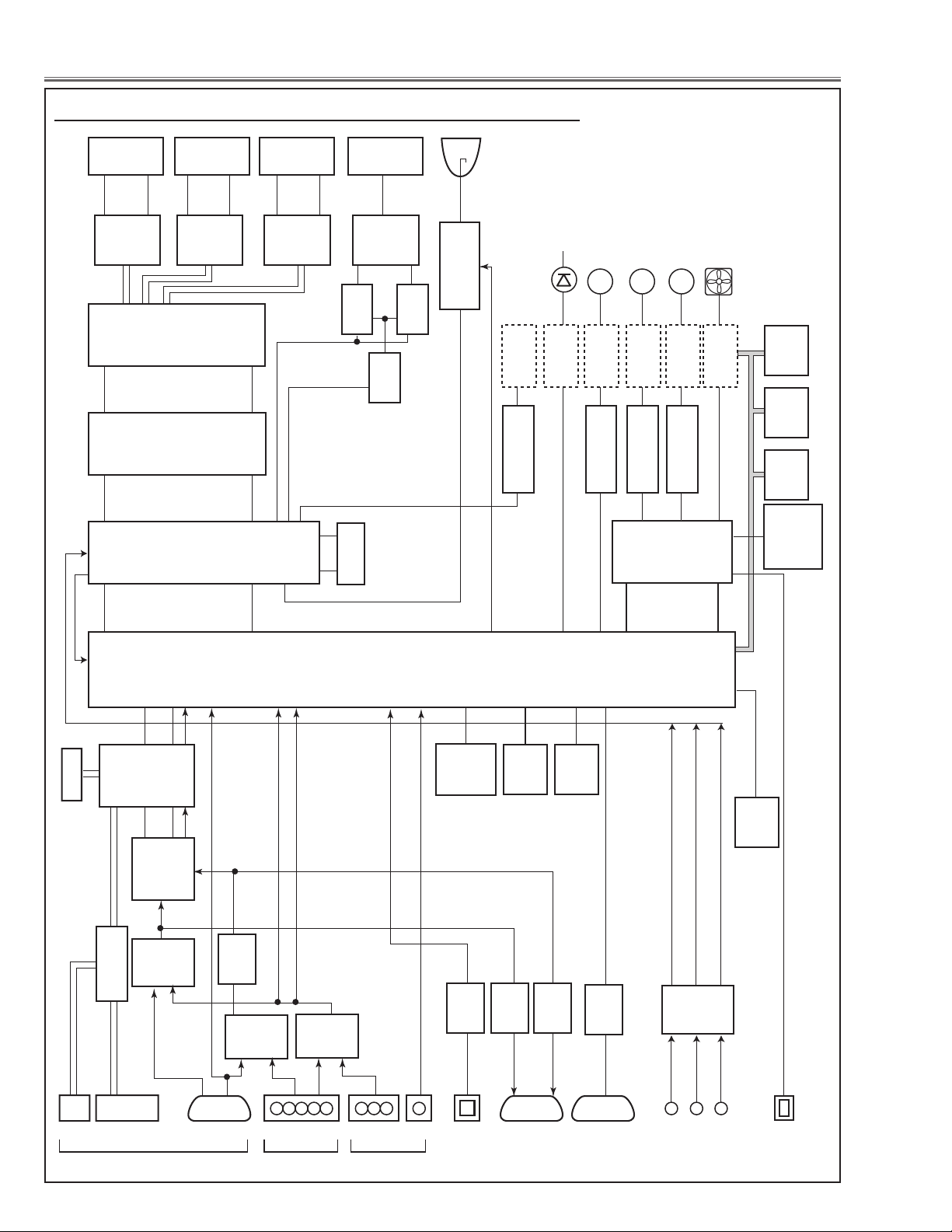
IC5801
SDRAM
DVI-D
HDMI
INPUT1INPUT2MONITOR
OUTPUT
D_SUB
RGB
RGB
RGB
Y,Cr,Cb
S-C, S-Y
S-C, S-Y
PJ-Net
BNCD_SUB LAN
SERIAL
PORT
D_SUB RCA
USB
S-VIDEO
W-RC
RC
RC
F-RC
R-RC
IC1011
SYNC SEP.
IC8001
HDMI RECEIVER
IC4001
BUFFER-SW
IC8301
NETWORK
IC4002
BUFFER
IC3801
RS-232C
IC2201
PC A/D
IC5201
PC/PJ-NET
SW FPGA
IC1311
IC1331
DDR
MEMORY
IC4801
I/O
EXPANDER
IC301
SCALER
&
SYSTEM
CONTROL
IC501
IC551
R-S/H
G-LCD
PANEL
R-LCD
PANEL
IC1501
IC1551
G-S/H
IC2501
IC2551
B-S/H
MOTOR
CONTROL
SHUTTER
CONTROL
FAN
CONTROL
LED
DRIVE
IC801
FLASH
MEMORY
IC1692
TEMP
SENSOR A
IC1816
TEMP
SENSOR B
IC1814
TEMP
SENSOR C
IC401
DIGITAL
GAMMA
H/V
H/V
H/V
H/V
H/V
USB+,-
INPUT3
MOTORS
(FOCUS/ZOOM)
FANS
M
MOTOR
CONTROL
MOTORS
(LENS SHIFT)
M
MOTOR
CONTROL
MOTOR
(FILTER)
M
LEDS
(PANEL)
IC1881
IC1882
ACCELE
SENSOR
IC1802
PRESS
SENSOR
(LAMP) (ROOM)
IC1387
EEPROM
D[0-7]
A[0-7]
KS_DRO
KS_DGO
KS_DBO
IC2301
KEYSTONE
PIC_RSIG
PIC_GSIG
PIC_BSIG
IC3401
Ye
CONTROL
FPGA
A[1-16]
D[0-15]
IC5001
RGB-SW
IC2001
BNC/RCA
SW
IC1002
SYNC
SW
CVBS
SCART_CV
B-LCD
PANEL
IC9830
OPTICAL
DRIVE
IC7401
D/A
IC5561
SHUTTER DRIVE
IC6501/IC6521
LENS SHIFT
IC5541
FILTER DRIVE
IC5501/IC5521
FOCUS/ZOOM
LAMP BALLAST
IC7406
SW
IC7402
SW
OPTICAL
FILTER
LAMP
IC3411
INVERTER
Chassis Description
Chassis over view
-72-
LHD700 Service Manual
020-000423-02 Rev.1 (01-2013)
Page 75
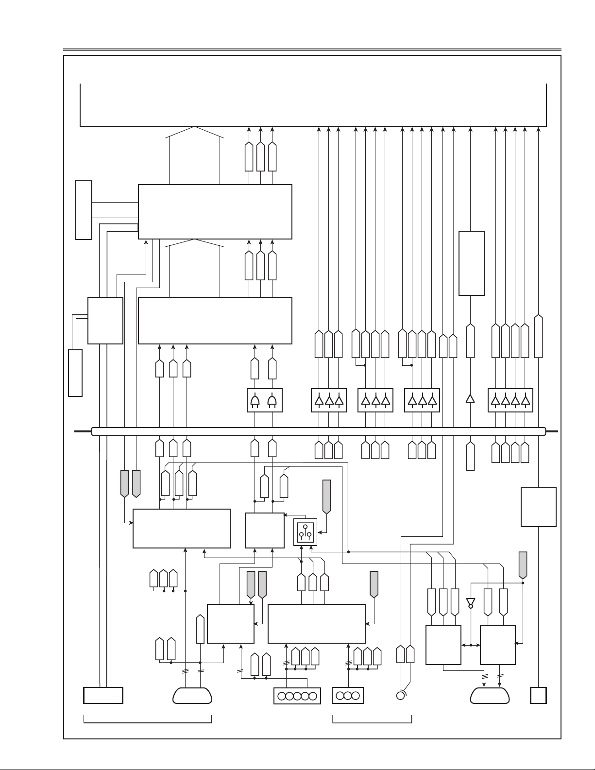
Chassis Description
DVI-D
PJ-Net
INPUT1
D_SUB15D_SUB15
INPUT2
BNC
13
11
1,3,5
8,10,12
1,3,5
13,3
12.5
562
7
15,17
RCALAN
INPUT3MONITOR
OUT
R/CR_OUT
G/Y_OUT
B/CB_OUT
HS_OUT
VS_OUT
OUT_SW
S-C
Y_IN3_PW
CB_IN3_PW
CR_IN3_PW
S-Y
SCART_CV
S-C
S-Y
IN3_VIDEO
SCART_CV_PW
INPUT2_VS_EX
INPUT2_HS_EX
VS_IN2
HS_IN2
VS_IN1
HS_IN1
-IN1/IN2
-BNC/RCA
Q251
IC2001
BNC/RCA-SW
<AD8183>
IC5001
IN1/IN2-SW
<AD8183>
IC1002
SYNC-SW
<TC4053>
IC4001
BUFFER-SW
<AD8075>
IC4002
BUFFER-SW
IC8301
NETWORK
RGB
HV
HV
RGB
Y,CR,CB
AV
MAIN
K21A K10A
RGB
Q4001
HV
IC301
<PW392>
SCALER
&
SYSCTM
CONTROL
8,10,12
10,12,14
3,6
IC1011
SYNC
SEP.
<BA7078>
IN2:H
-BNC/RCA
RCA:H
OUT:H
IN1:H
974240
122
20
22
-IN1/IN2
Y:H
5
1
3
22
7
5
3
1
1
7
5
2
9,11
14
201816
4
10
18
16
123
27
31
133
240
338
107
103
212
102
108
318
104
206
307
445,356
97
400
131
82
25
IN0HS
IN0VS
IN0CLK
CG_HSYNC
CG_VSYNC
120
38
CG_CLK
IC5201
PC/PJ-NET SW
FPGA
<XC3S50A>
IC2201
A/D
<ISL51002>
IC8001
HDMI
RECEIVER
<SII9127>
HDMI
IN0B[0-9]
IN0G[0-9]
IN0R[0-9]
CG_B[0-9]
CG_G[0-9]
CG_R[0-9]
SI_HS
SI_VS
SI_CLK
R/CR
G/Y
B/CB
R/CR
G/Y
B/CB
49
VSOUT
50
HSOUTHS
VS
HS_OUT
VS_OUT
7
3
5
2
IC261
8116
3
5
2
12
9
IC262
141210
537
IC231
Y_IN
CB_IN
CR_IN
Y_IN3
CB_IN3
CR_IN3
SCART_CV
IC1006
75
89
|
100
83
79
-IN1/IN2
-BNC/RCA
46
42
66
62
474339
315835
747882910
70
R_IN2_PW
G_IN2_PW
B_IN2_PW
IN2_VIDEO
109
209
210
311
141210
537
IC221
R_IN2
G_IN2
B_IN2
515955
R_IN1_PW
G_IN1_PW
B_IN1_PW
313
213
105
141210
537
IC211
R_IN1
G_IN1
B_IN1
637167
Q1341,Q1342, Q1342,
Q1344, Q1345
AMP
VS_IN2
HS_IN2
VS_IN1
R_IN1
G_IN1
B_IN1
R_IN2
G_IN2
B_IN2
CR_IN3
Y_IN3
CB_IN3
HS_IN1
R/CR_OUT
G/Y_OUT
B/CB_OUT
INPUT1_VS_EX
INPUT1_HS_EX
TXD_MCI/RXD_MCI
Input & signal processing stage
LHD700 Service Manual
020-000423-02 Rev.1 (01-2013)
-73-
Page 76
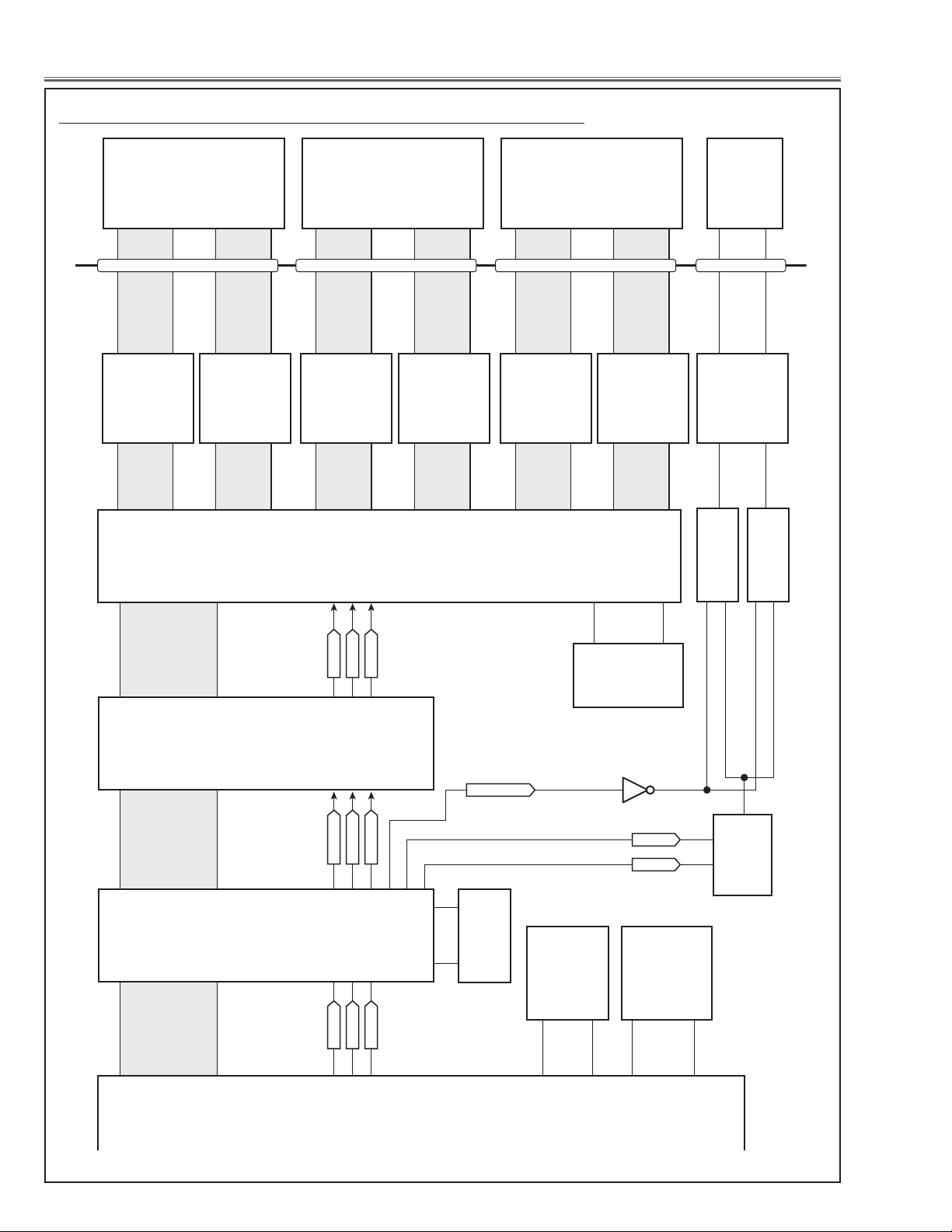
Chassis Description
KS_DRO[0-9]
KS_DGO[0-9]
KS_DBO[0-9]
2
87
85
81
82
159
1180
1249
1100
IC1311
IC1331
DDR
MEMORY
IC801
FLASH
MEMORY
IC301
SCALER
&
SYSTEM
CONTROL
<PW392>
IC501
R-S&H
<CXA7010>
IC551
R-S&H
<CXA7010>
R-LCD
PANEL
MAIN
KS_DVS
KS_DHS
KS_DCLK
PW_DRE[0-9]
PW_DGE[0-9]
PW_DBE[0-9]
PIC_RSIG[0-9]
PIC_GSIG[0-9]
PIC_BSIG[0-9]
MA[0-12]
MD[0-15]
A[1-22]
D[0-15]
380
285
381
145
1
1 13
51 7
214
69
50
129
141
45
125
37
PW_DVS
PW_DHS
PW_DCLK
PIC_VSYNC
PIC_HSYNC
PIC_CLK
4LCD_SW_NIOS
4LCD_SCL
Q7403
4LCD_SDA
IC1501
G-S&H
<CXA7010>
IC1551
G-S&H
<CXA7010>
K35R
K35G
K35B
G-LCD
PANEL
IC2501
B-S&H
<CXA7010>
IC2551
B-S&H
<CXA7010>
IC9830
OPTICAL
DRIVE
<BA3472>
IC7402
SW
<TC7W53>
IC1401
IC1431
IC1461
DDR
MEMORY
IC7406
SW
<TC7W53>
B-LCD
PANEL
OPTICAL
FILTER
K25Y
IC2301
KEYSTONE
<PW610>
IC3401
Ye
CONTROL
FPGA
<EP3C80F484>
IC5801
SDRAM
IC7401
D/A
<M62334>
IC401
DIGITAL
GAMMA
CORRECTION
<CXD3550>
1
2
5
6
LCD drive stage
-74-
LHD700 Service Manual
020-000423-02 Rev.1 (01-2013)
Page 77
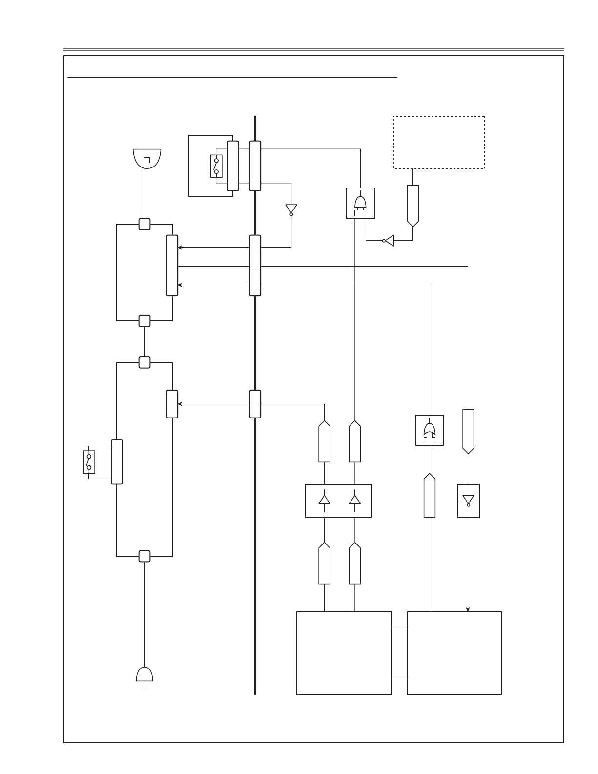
Chassis Description
SW1861
LAMP COVER-SW
IC301
SCALER
&
SYSTEM
CONTROL
<PW392>
IC3401
Ye
CONTROL
FPGA
<EP3C80F484>
LAMP
LP900
AC
SW905
THERMAL
PROTECTOR
A902
POWER
A901
LAMP
BALLAST
Q1861
Q7796
LB_PIC_UART
PF_FAN
PFC_SW_EX
PIC_LB_UART
LAMP_SWIN_EX
LAMP_SWIN
PFC_SW
IC3402
IC1853
IC1854
IC1875
COVER SW.
1
2
2 4
32 17
4
78
155
250
25
25
5 1 4
5 1 4
3 1
3 1
K10B
CN6A
CJ1
CJ2
K6C
K6A K6B
K8K K8B
24
3
182
POWER-ON:H
POWER-ON:H
MAIN
FAN
CONTROL
Lamp control stage
LHD700 Service Manual
020-000423-02 Rev.1 (01-2013)
-75-
Page 78
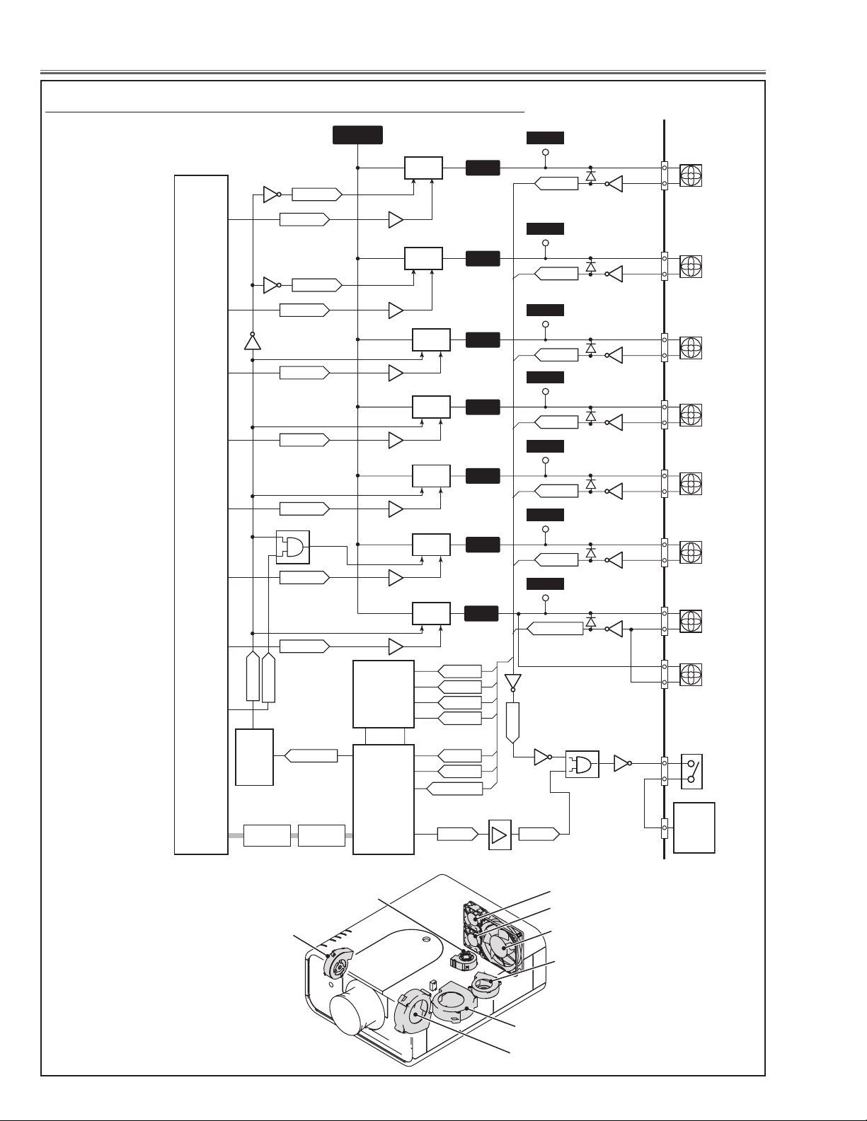
Chassis Description
IC301
SCALER
&
SYSTEM
CONTROL
<PW392>
IC4801
I/O
EXPANDER
<TE7783>
IC7801
DAC
FAN
CONTROL
<M62393>
K78F
FN902
(PANEL)
TPFN5
16V
FAN5
IC7721
Q7722
FAN_CONT5
FAN_ENB1
PF_FN902
Q7782
Q7784
FAN_ENB3
Q7783
3
7 5
2
IC7701
3
7 5
2
Q7792
D7722
PF_FN904
Q7891
PF_FN901
Q7793
K78G
FN901
(PANEL)
TPFN6
K78E
FN904
(LAMP)
TPFN4
TPFN7
IC7881
3
42
1
K78H
FN908
(PBS)
FAN_CONT6
FAN_CONT4
5
4
12
2, 3
PF_FN908
Q7942
IC7921
3
42
1
FAN_CONT7
7
K78A
FN907
(POWER)
TPFN1
PF_FN907
PF_FN907
PF_FN908
PF_FN904
PF_FN903
PF_FN902
PF_FN901
Q7842
IC7821
3
42
1
FAN_CONT1
15
K78B
FN903
(LAMP)
TPFN2
PF_FN903
Q7843
IC7841
IC7802
AND
3
42
1
FAN_CONT2
14
K78C
FN905
(EXHAUST)
TPFN3
K78D
K8B
FN906
(EXHAUST)
SW901
PF_FN905&FN906
PF_FN905&FN906
Q7794
Q7796
Q7797
Q7796
IC7861
IC1875
IC1854
IC1871
BUFFER
3
61
62
63
64
33
41
154
4
2
1
2
4
1
17
137
250
FAN_CONT3
FAN_DRIVE_B
13
6
2
PW_SCL0_S5V
PW_SDA0_S5V
PW_SCL0
PW_SDA0
FAN_DRIVE_CPU
FAN_DRIVE
FAN6
FAN6
FAN7
FAN1
FAN2
FAN3
Q7702
Q7881
Q7921
Q7821
Q7841
Q7861
D7702
D7891
D7922
D7822
D7842
D7866
PF_FAN
LAMP_SWIN_EX
LAMP_SWIN
K8K
LAMP
BALLAST
Error: H
On: H
On: H
Error: L
Fan control stage
FN908
FN905
FN906
FN907
-76-
FN904
FN903
FN902
FN901
LHD700 Service Manual
020-000423-02 Rev.1 (01-2013)
Page 79

Chassis Description
1
2
3
4
K8M
K8L
K8L
K8N
8
9
10
11
2
3
4
5
6
LENS_TOP_EX
LENS_BOT_EX
LENS_R_POSI_EX
LENS_L_POSI_EX
LENS_C_POSI_EX
FOCUS+
M
FOCUS-
ZOOM+
ZOOM-
IC4801
I/O
EXPANDER
<TE7783>
IC1872
BUFFER
<TC74ACT>
IC6531
SW
<TC7W53>
IC6541
SW
<TC7W53>
IC301
SCALER
&
SYSTEM
CONTROL
<PW392>
IC3401
Ye
CONTROL
<EP3C80F484>
IC5501
FOCUS
DRIVE
<BA6287>
5 1
74
5 1
74
16
15
IC5521
ZOOM
DRIVE
<BA6287>
ZOOM
FOCUS
M
4
5
2
3
4
2
1
5
IC5541
STEPPING
MOTOR
DRIVE
<NJM2671>
1
9
5
7
IC5561
MOTOR
DRIVE
<BA6287>
IC3411
FILTER
M
K8P
3
5
2
1
SHUTTER
M
LENS_UP
LENS_DOWN
LENS_LEFT
LENS_RIGHT
18
1
5
9
520
IC6501
UP/DOWN
DRIVE
<BA6920>
LENS SHIFT
UP/DOWN
M
18 9
340
17
18
241
134
19
178
185
520
IC6521
LEFT/RIGHT
DRIVE
<BA6920>
LENS SHIFT
LEFT/RIGHT
M
14
13
12
11
FOCUS+_EX
FOCUS-_EX
ZOOM+_EX
ZOOM-_EX
6
7
8
9
76
6
5
LENS_UD_SW
LENS_UD_PWM
LENS_LR_PWM
LENS_LR_SW
F_MOTOR_SW
2
3
4
7
77
8
7
5
11
7
152
39
40
443
LENS POSITION
SENSOR
STOP UP DOWN
LENS_UD L H H
LENS_UD_SW ANY L H
STOP RIGHT LEFT
LENS_LR L H H
LENS_LR_SW ANY L H
STOP + -
FOCUS - H H L
FOCUS + H L H
STOP + -
ZOOM - H H L
ZOOM + H L H
MOTOR_STEP
84
5
8
6
SHUTTER_SW+
85
83
160
4
SHUTTER_SW-
SHUTTER_POSI1_EX
SHUTTER_POSI2_EX
SHUTTER_POSI1
SHUTTER_POSI2
1
5
8
7
Motor control stage
LHD700 Service Manual
020-000423-02 Rev.1 (01-2013)
-77-
Page 80
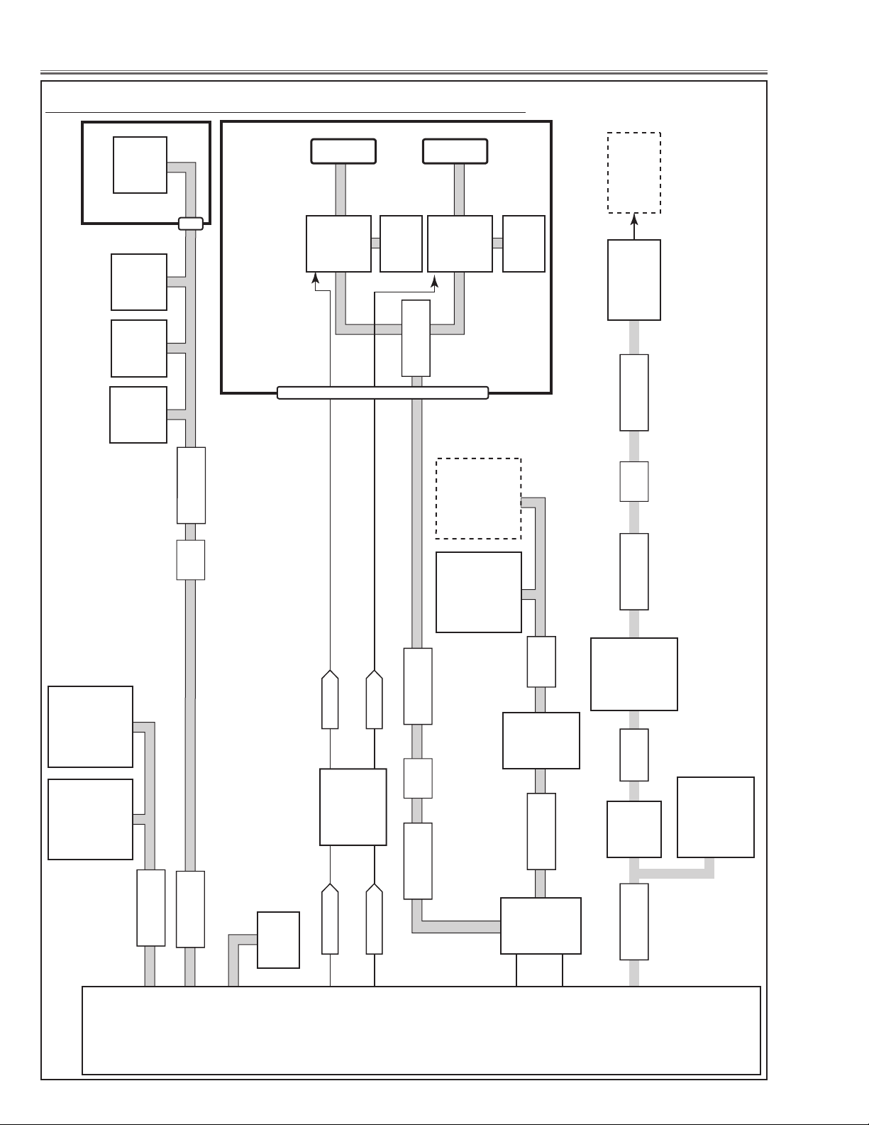
Chassis Description
IC1692
TEMP.
(ROOM)
<MCP9801>
Q1361
Q1363
Q7401
Q7402
Q1368
Q1366
PW_SDA3
PW_SCL3
20,135
246
159
155
164
355,444
PW_SDA_DDC_A
PW_SCL_DDC_A
IC1003
BUS-SW
<TC74LVX>
IC1004
VGA-DDC
MEMORY
IC1012
IC1013
BUS-SW
<TC74LVX>
IC1014
DVI-DDC
MEMORY
IC1387
MEMORY
50,51
52,53
259,351
153,258
IC8001
HDMI
RECEIVER
<SII9127>
PW_SDA0
PW_SCL0
DDC_SDA
DDC_SCL
DDC_SDA_S5V
DDC_SCL_S5V
PW_SDA0_S5V
PW_SCL0_S5V
DSUB_DDC_SW_CPU
DVI_DDC_SW_CPU
DSUB_DDC_SW
DVI_DDC_SW
DSub15 DVI-D
IC2201
A/D
<ISL51002>
IC1814
TEMP.
(PANEL)
<MCP9801>
IC7801
FAN
CONTROL
<M62393>
IC1816
TEMP.
(LAMP)
<MCP9801>
IC1871
BUFFER
<TC74ACT541>
K8X
K10A K21A
IC401
DIGITAL
GAMMA
<CXD3550>
IC7401
D/A
<M62334>
PANEL DRIVE
S&H CIRCUIT
IC501, IC551
IC1501, IC1551
IC2501, IC2551
OPTICAL
FILTER
GAMMA_SCL
GAMMA_SDA
HSCL
HSDA
4LCD_SDA
4LCD_CLK
4LCD_SDA_NIOS
4LCD_CLK_NIOS
PW_SDATA_OUT
PW_SCLK_OUT
SDAT_PIC
SCLK_PIC
IC1471
BUS-SW
<TC7WBL125>
IC1371
BUS SW
IC4801
I/O
EXPANDER
<TE7783>
IC3401
Ye
CONTROL
<EP3C80F484>
IC2301
KEYSTONE
<PW610>
AV
MAIN
RC FRONT
IC301
SCALER
&
SYSTEM
CONTROL
<PW392>
Bus control stage
-78-
LHD700 Service Manual
020-000423-02 Rev.1 (01-2013)
Page 81
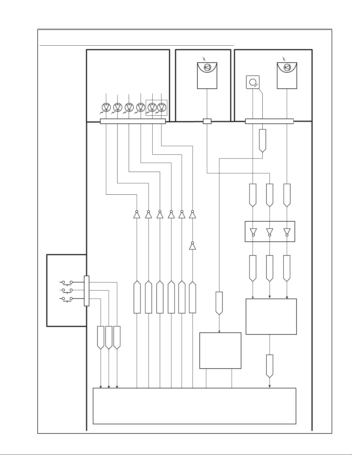
Chassis Description
IC301
SCALER
&
SYSTEM
CONTROL
<PW392>
IC3401
Ye
CONTROL
<EP3C80F484>
POWER_ON
Wired RC
Jack
AU2801
RC Pre-Amp.
AU2802
RC Pre-Amp.
K28B
K10A
R/C
AV
MAIN
144
8
25
24
23
K21A
K8X
7
K8J
K8H
2 3 4
Q5848
D6885
KEY01-03
142,249,143
KEY11-31
27,28,29
W_RC_PIC1
F_RC_PIC1
R_RC_PIC1
W_RC
W _RC_SW
W _RC_SW
F_RCPW_R/C
R_RC
WARNING FILTER
Q5894
D6884
LAMP REPLACE
TEMP_LED
Q5869
D6883
WARNING TEMP
LAMP_LED
Q5855
D6882
LAMP
POWER_LED
Q5861
D6881
Q5862
131
52
292
13
97
12
3
4
264
11
10
D[0-7]
A[0-7]
POWER
SHUTTER
Key Switches
IC3411
INVERTER
IC2801
BUFFER-SW
IC4801
I/O
EXPANDER
<TE7783>
34
147
252
SHUTTER_LED
Q5856
349
438
148
292
3
5
6
7
2
4
FILTER_LED
LAMP_REP_LED
LED drive & RC control stage
LHD700 Service Manual
020-000423-02 Rev.1 (01-2013)
-79-
Page 82
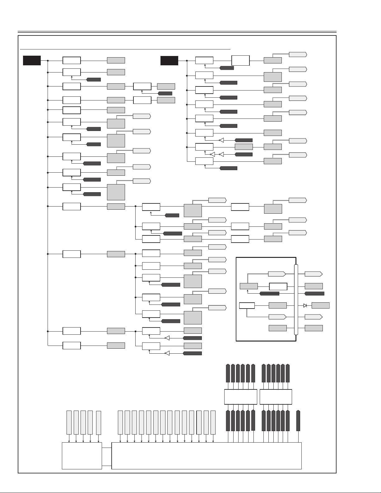
Chassis Description
S16V
32
347
348
146
149
441
99
251
4
A[0-7]
D[0-7]
IC4801
<I/O EXPANDER>
IC301
<SCALER>
ON_1.8V
S3.3V1
ON_25V
FPGA_ON
PFC_SW_EX
IC_RESET_CPU
POWER_SW_LAN
IC_RESET
137
FAN_DRIVE_CPU
FAN_DRIVE
247
SW_1.8VGAM_EX
SW_1.8VGAM
346
SW_2.5VGAM_EX
SW_2.5VGAM
437
SW_3.3VGAM_EX
SW_3.3VGAM
248
SW_1VGAM_EX
SW_1VGAM
S6V
S2.5V_USB
IC1391
25V
Q7432
IC7431
Q7433
S1.8VPW
IC5651
S3.3V1
IC5611
S3.3VPWA
IC5631
S3.3VPW
IC5674
S1.2V_PIC1
S1.2V_PIC1D
IC6402
S1.8VPWA
IC5661
IC_RESET
3.3VAD
A3.3V_AD
D3.3V_AD
IC2251
A1.8V_AD
D1.8V_AD
IC2261
S2.6VPW
IC2271
PF_PIC
IC1871
BUFFER
PFC_SW
SW_1.8V_KS_EX
SW_1.8V_KS
SW_2.5V_KS_EX
SW_2.5V_KS
SW_3.3V_KS_EX
SW_3.3V_KS
ON_SI_SW_CPU
ON_SI_SW
35
ON_25V_EX
ON_25V
IC1875
BUFFER
282
PF_KS
180
PF_GAM
PF_LAN
69
PF_25V
67
PF_FRT
138
PF_AD
145
PF_SI
345
PF_AV
33
PF_FN90841PF_FN907
154
PF_FN905&FN906
251
PF_PIC
25
PF_9V
293
PF_S12V
61
PF_FN90162PF_FN90263PF_FN90364PF_FN904
PF_PIC
SW_3.3V_KS
S3.3VAA_KS
S3.3VAB_KS
IC2391
PF_KS
SW_1.8VGAM
1.8V_DDR
IC3571
PF_GAM
SW_1VGAM
1.0V_DI_C
1.0V_DDR
1.0V_DI_TX
1.0V_DI
IC3581
S4.3V1
IC6611
PF_GAM
PF_AD PF_AD
S3.3VSI
IC8051
S1.2VSI
IC8061
PF_SI PF_SI
S3.3VFRT
IC5261
S1.2V_FRT_INI
IC5291
PF_FRT PF_FRT
SW_2.5V_KS
ON_SI_SW
LAN_POW_SW LAN_POW_SW
ON_SI_SW
S2.5V_PIC1A
S2.5VAB_KS
S2.5VAC_KS
S2.5VAA_KS
IC6403
S4.3V2
IC6601
Q8081
S5V
IC5881
S3.3V
IC5891
PF_AD
S3.3V_PIC1
S3.3V_LAN S5V
5VDVI1
IC6401
PF_PIC
IC2381
PF_KS
SW_2.5VGAM
2.5V_DI_TX
2.5V_DI
2.5V_DI_RX
IC3566
PF_GAM
SW_3.3VGAM
3.3V_DI
3.3V_SH
IC3561
PF_GAM
S4.3V2
S1.8VSK_KS
S1.8VMPLL_KS
S1.8VAA_KS
IC2371
PF_KS
K21A
K10A
AV
D201
PF_LAN PF_LAN
PF_AV
PF_AV
1
22
80
5
14
27
Q2082
PF_25V
PNL15V_ON
S3.3V
HVDD
VVDD
IC3516
PF_GAM
SH15V_ON
15V_SHR
IC3511
PF_GAM
SH15V_ON
15V_SHG
IC3531
PF_GAM
SH15V_ON
15V_SHB
IC3551
IC_RESET
15V_LNS
IC6612
PF_GAM
PF_9V
S5VSI
Q8082
S1.8VPW
Q5864
K8H-1
Q8082
Q6613
IC_RESET
9V_LNS10VA
IC6606
PF_S12V
S12V
IC5542
Q6622Q6621
IC8341
S6VS6V
5VDVI1
Power supply & power failure circuit
-80-
LHD700 Service Manual
020-000423-02 Rev.1 (01-2013)
Page 83
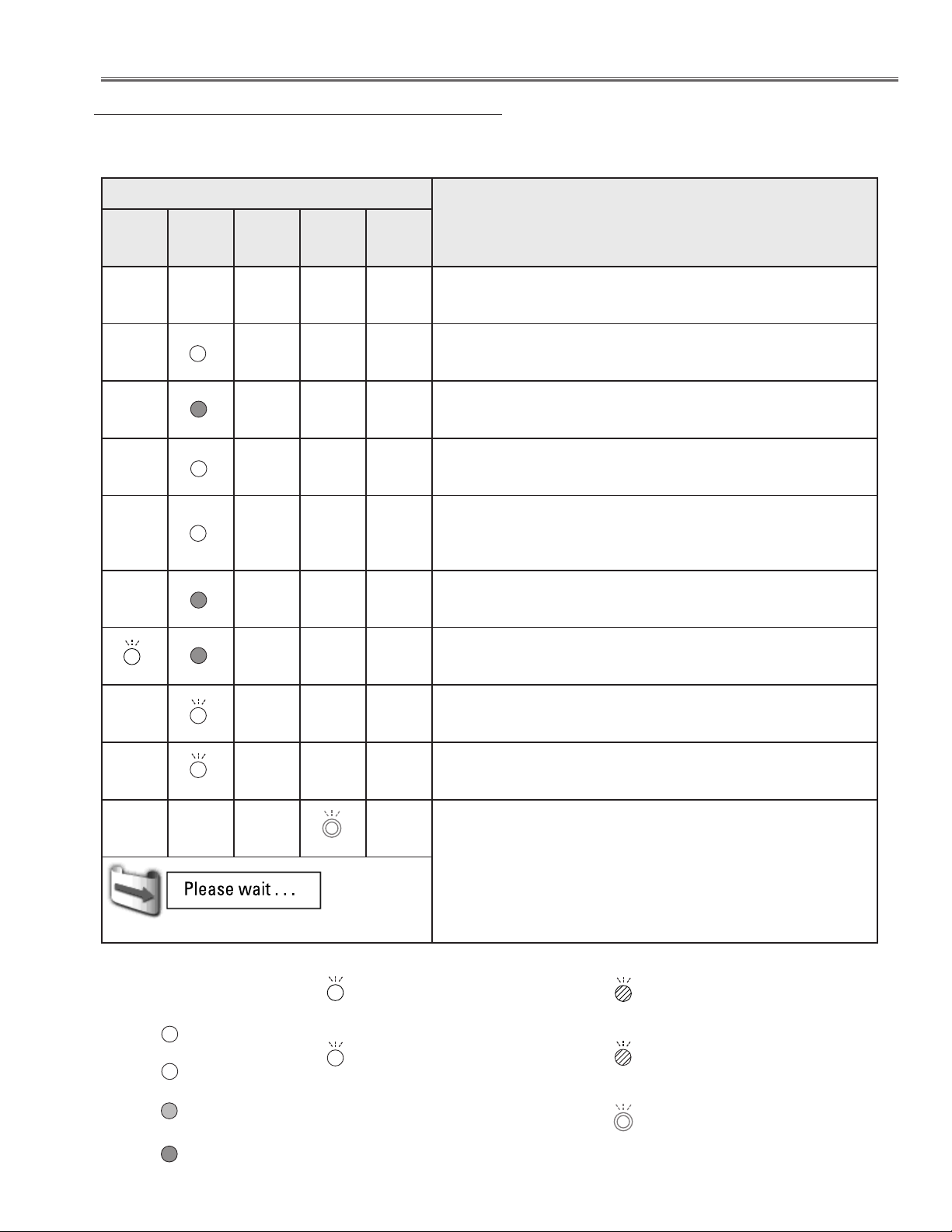
Chassis Description
❊
❊
❊
❖
❖
❖
❖
❊
❖
❖
❖
❊
❊
Indicators and Projector Condition
Check the indicators for the projector condition.
The projector is operating normally.
Indicators
POWER
green
LAMP/
SHUTTER
red/blue
LAMP
REPLACE
orange
WARNING
FILTER
orange
WARNING
TEMP.
red
Projector condition
j j j j j
J
J
J
j
j
j
✽ ✽ ✽
✽ ✽ ✽
✽ ✽ ✽
✽ ✽ ✽
✽ ✽ ✽
✽ ✽ ✽
✽ ✽ ✽
The projector is off. (The AC power cord is unplugged.)
The projector is in stand-by mode. Press the ON/STAND-BY
button to turn on the projector.
The projector is operating normally.
(The shutter is open)
The projector is operating normally.
(The shutter is closed)
The projector is preparing for stand-by or the projection lamp
is being cooled down. The projector cannot be turned on until
cooling is completed and the POWER indicator lights green.
The projection lamp is being cooled down in the Power
management mode.
The projector is in the Power management mode.
The projection lamp is being cooled down in the Shutter
management mode.
J
J
Fig.1 Filter replacement icon and “Please wait...”
LHD700 Service Manual
020-000423-02 Rev.1 (01-2013)
✽ ✽ ✽
• • • on
J
• • • on (red)
• • • on (blue)
• • • dim
• • • dim (red)
✽ ✽ ✽
• • • blinking at the normal rate
(approx. 1 second ON,
1 second OFF)
• • • blinking at the normal rate (blue
and dim red) (approx. 1 second
ON, 1 second OFF)
• • • off
j
• • • Differ according to conditions.
✽
The projector is in the Shutter management mode. Press the
ON/STAND-BY button to turn on the projector.
The filter is scrolled using the FILTER button on the remote
control or the Filter control function in the setting menu. When
the filter is being scrolled, the Filter replacement icon and
“Please wait...” message (Fig. 1) appear on the screen for
about 30 seconds.
• • • blinking fast
(approx. 0.5 seconds ON, 0.5
seconds OFF)
• • • blinking fast (blue and dim red)
(approx. 0.5 seconds ON, 0.5
seconds OFF)
• • • blinking slow
(approx. 2 seconds ON, 2
seconds OFF)
-81-
Page 84
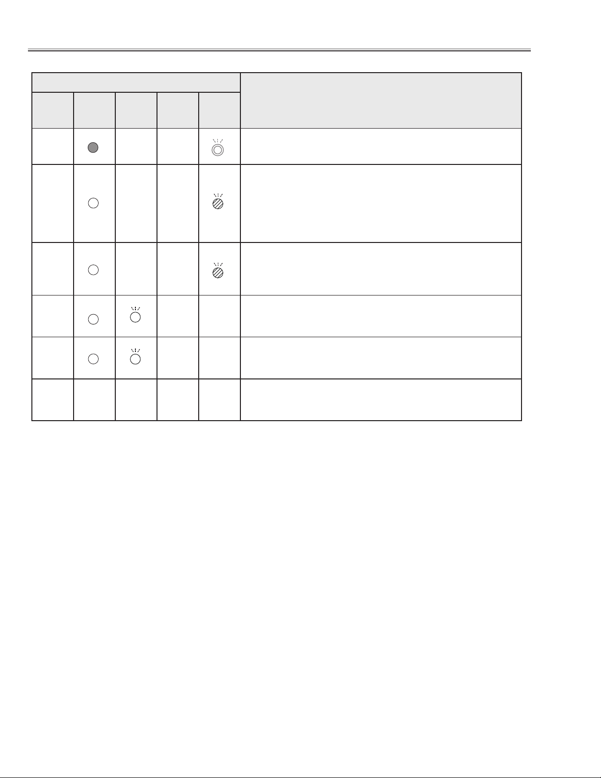
Chassis Description
❖
❖
❖
❖
❖
The projector is detecting abnormal condition.
Indicators
POWER
green
LAMP/
SHUTTER
red/blue
LAMP
REPLACE
orange
WARNING
FILTER
orange
WARNING
TEMP.
red
Projector condition
J
j
J
j
J
J
✽
✽ ✽
✽ ✽
✽ ✽
J
✽ ✽
✽ ✽
✽ ✽
The temperature inside the projector is elevated close to the
abnormally high level.
The temperature inside the projector is abnormally high. The
projector cannot be turned on. When the projector is cooled
down enough and the temperature returns to normal, the
POWER indicator lights green and the projector can be turned
on. (The WARNING TEMP. indicator keeps blinking.) Check
and replace the filter.
The projector has been cooled down enough and the
temperature returns to normal. When turning on the projector,
the WARNING TEMP. indicator stops blinking. Check and
replace the filter.
The lamp cannot light up. (The projector is preparing for
stand-by or the projection lamp is being cooled down. The
projector cannot be turned on until cooling is completed.)
The lamp cannot light up. (The lamp has been cooled down
enough and the projector is in stand-by mode and ready to be
turned on with the ON/STAND-BY button.)
The lamp has been used overtime. Replace the lamp
immediately and then reset the lamp counter. The indicator
will be turned off after resetting the counter.
WARNING FILTER
When the filter detects clogging, reaches a time set in the timer setting or runs out of the filter scroll, the WARNING
FILTER indicator lights orange. When this indicator lights orange, replace the filter or the filter cartridge with a new one
promptly. Reset the Filter counter and Scroll counter after replacing the filter cartridge.
LAMP REPLACE
When the projection lamp reaches its end of life, the LAMP REPLACE indicator lights orange. When this indicator lights
orange, replace the projection lamp with a new one promptly. Reset the lamp counter after replacing the lamp.
-82-
020-000423-02 Rev.1 (01-2013)
LHD700 Service Manual
Page 85
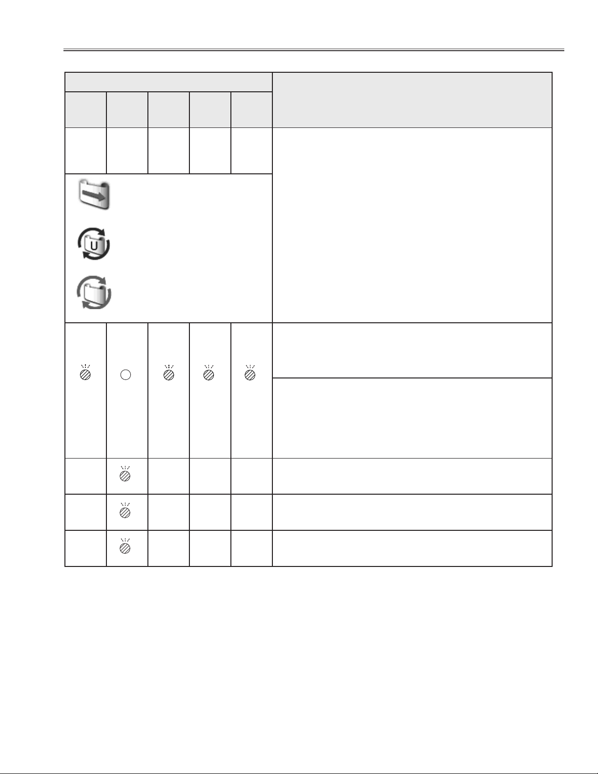
Chassis Description
❊
❊
❊
❖
The projector is detecting abnormal condition.
Indicators
POWER
green
J
Fig.2 Filter replacement icon
Fig.3
Fig.4 Filter cartridge replacement icon
LAMP/
SHUTTER
red/blue
✽ ✽
LAMP
REPLACE
orange
WARNING
FILTER
orange
J
WARNING
TEMP.
red
✽
If the filter counter reached a time set in the timer setting, a
Filter replacement icon (Fig.2) appears on the screen and
the WARNING FILTER indicator on the top panel lights up.
Replace the filter as soon as possible. If the filter is out of
scroll and the projector reaches a time set in the timer setting,
Fig. 3 appears on the screen and the WARNING FILTER
indicator lights up. Replace the filter cartridge as soon as
possible.
If the filter is clogged and no scroll is left in the filter cartridge,
a Filter cartridge replacement icon (Fig.4) appears on the
screen and the WARNING FILTER indicator lights up.
Replace the filter cartridge as soon as possible.
Note:
• Fig.2, Fig.3 and Fig.4 icon will not appear when the Display function is set to “Off” or during “Freeze”.
Projector Condition
✽ ✽ ✽ ✽
j
J
✽ ✽
✽ ✽
j
j
The filter cartridge is not installed in the projector. Check the
filter compartment to see if the filter cartridge is installed in
the projector. When the filter cartridge is installed and the
indicators continue to light and blink, read the column below.
The projector detects an abnormal condition and cannot be
turned on. Unplug the AC power cord and plug it again to turn
on the projector. If the projector is turned off again, unplug the
AC power cord and contact the dealer or the service center.
Do not leave the projector on. It may cause an electric shock
or a fire hazard.
The shutter is out of control.
The shutter is out of control. (The projector is in the cooling
mode.)
The shutter is out of control. (The projector is in the stand-by
mode.) In that case, contact the service station immediately.
LHD700 Service Manual
020-000423-02 Rev.1 (01-2013)
-83-
Page 86
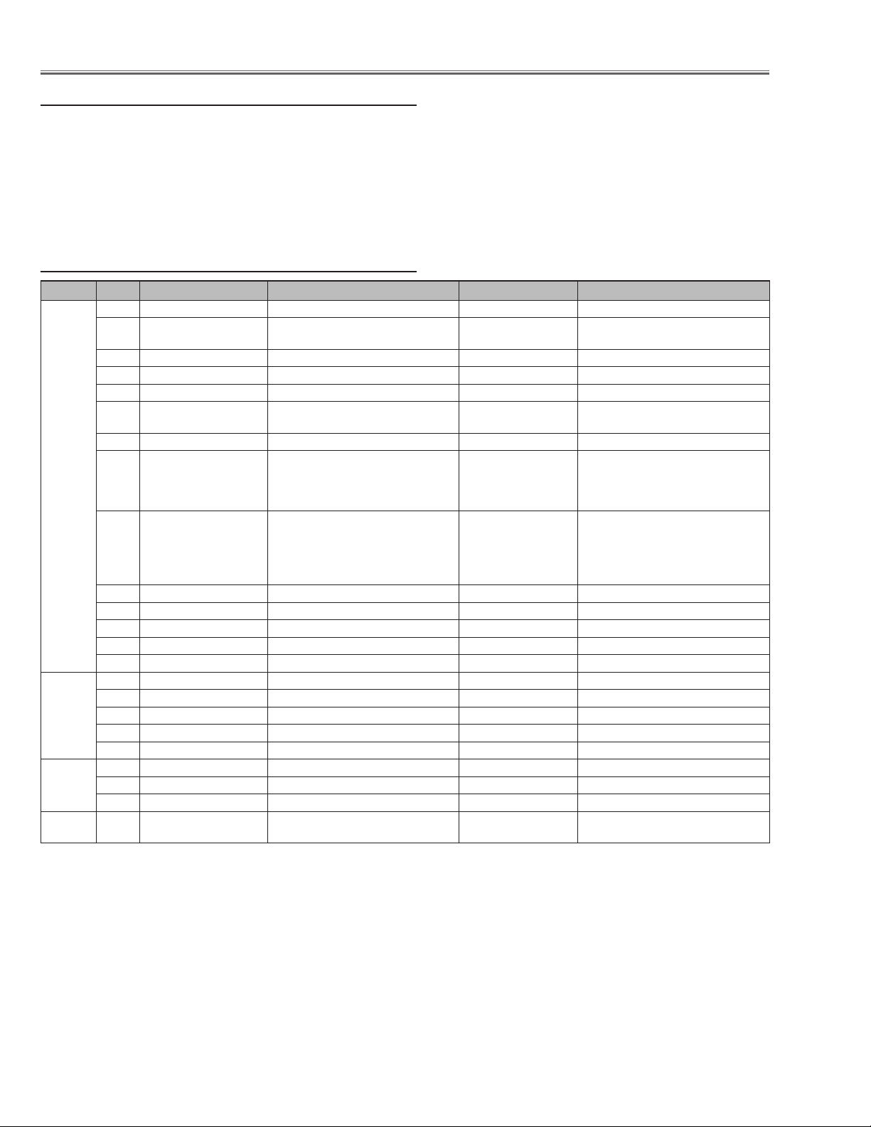
Chassis Description
Power failure detection system
Detection of power failure
Projector provides a protection circuit to prevent the secondary failure when the power failure, fans failure or temperature failure occurs on the projector. The power failure detection lines "PF_AV", "PF_AD", etc. are connected to
the main power supplies and fans. When the failure occurs, IC301<SCALER> receives an error information and then
outputs the signal "PFC_SW_EX" from pin 32. The signal "PFC_SW_EX" is supplied to power supply circuit as the
signal "PFC_SW" via IC1875 <Buffer> to control the power supply operation.
Error information table
IC Pin Signal Name Connection Lines Error Information Failure Area
345 PF_AV S5V, S-5V AV, AV S5V, S-5V on AV board
IC301
PW392
IC4801
TE7783
IC301
PW392
IC3401
138 PF_AD
PF_SI S3.3VSI, S1.2VSI MAIN,
245
67 PF_FRT S3.3VFRT, S1..2V_FRT_INI MAIN,
PF_5V_PJ 5V_PJ PJ-NET,
257
PF_PIC
251
60 PF_25V 25V MAIN,
PF_KS
282
PF_GAM
180
PF_9V 9V_LNS MAIN,
25
293 PF_S12V S12V MAIN,
PF_FN905&FN906
154
PF_FN907 FN907 POWER & LOCK MAIN,
41
PF_FN908 FN908 POWER & LOCK MAIN,
33
PF_FN901 FN901 POWER & LOCK MAIN,
61
62
PF_FN902 FN902 POWER & LOCK MAIN,
63 PF_FN903 FN903 POWER & LOCK MAIN,
PF_FN904 FN904 POWER & LOCK MAIN,
64
PF_LAN S3.3V_LAN AV,
99
343 FILTER_DET FILTER CONDITION DETECT
388
FILTER_COUNT
PRESS_SENS
281
83
SHUTTER_POS1_PIC1
160
SHUTTER_POS2_PIC1
3.3VAD, A3.3V_AD, D3.3V_AD,
A1.8V_AD, D1.8V_AD, S2.5V_PICA
S1.2V_PIC1, S1.2V_PIC1D,
S3.3V_PICD
S1.8VSK_KS, S1.8VMPLL_KA,
S1.8VAA_KS, S3.3VAA_KS,
S3.3VAB_KS,S2.5VAB_KS,
S2.5VAA_KS, S2.5VAC_KS
1.8V_DDR, 1.0V_DI_C, 1.8V_DDR,
1.8V_DI_TX, 3.3V_DI, 3.3V_SH,
2.5V_DI_TX, 2.5V_DI_RX,
2.5V_DI, HVDD, VVDD, 15V_SHR,
15V_SHG, 15V_SHB
FN905, FN906 POWER & LOCK MAIN, FAN3 FN905&FN906 Power FAN3 & Lock
MOTOR ERROR DETECT
PRESSURE SENSOR DETECT
SHUTTER POSITION SW ERR,
AD
MAIN,
SI Main HDMI Power
F-FPGA
5V
MAIN,
PIC Main FPGA IC3401 Power
25V
KEYSTONE
MAIN,
GAM
MAIN,
9V Main 9V Power
S12V
FAN1
FAN7
FAN6
FAN5 FN902 Power FAN5 & Lock
FAN2
FAN4
LAN
ERR,
FIL_DET
FIL_MTR
ERR,
ERR, PRESSURE Pressure Error
SHUT_MTR
Main AD Power
Main FPGA IC5201 Power
Network Box Power
Main 25V Power
MAIN Keystone Power
Main Gamma Power
Main S12V
FN907 Power FAN1 & Lock
FN908 Power FAN7 & Lock
FN901 Power FAN6 & Lock
FN903 Power FAN2 & Lock
FN904 Power FAN4 & Lock
AV S3.3V_LAN
Filter Cartridge is not installed
Filter Motor Error
Shutter Operation Error
-84-
LHD700 Service Manual
020-000423-02 Rev.1 (01-2013)
Page 87
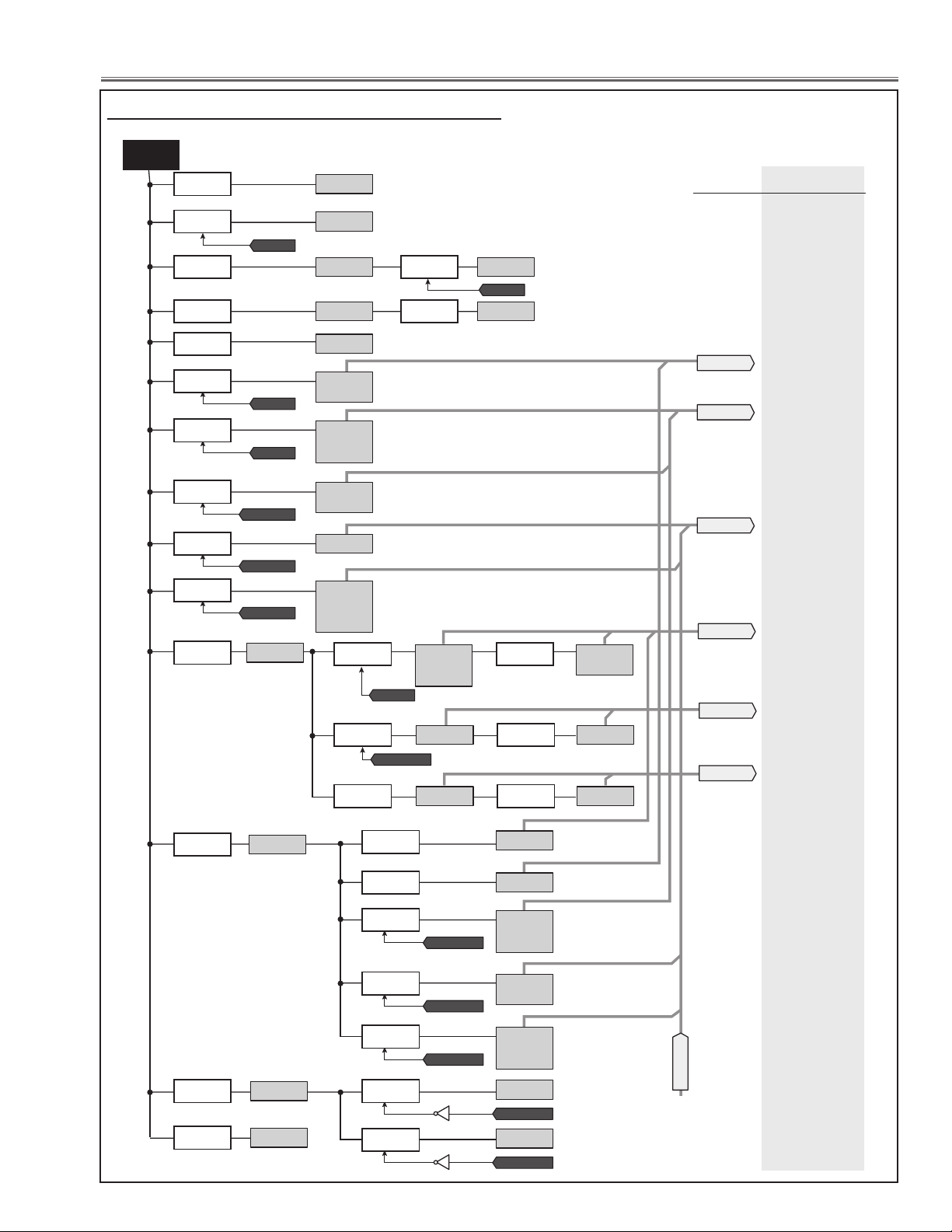
Chassis Description
ERROR INFO.
DETECTION
LINE NAME
MAIN, GAMMA
MAIN, KEYSTONE
MAIN, PIC
MAIN, F-FPGA
MAIN, AD
MAIN, SI
ON_1.8V
S3.3V1
FPGA_ON
S6V
S2.5V_USB
IC1391
S1.8VPW
IC5651
S3.3V1
IC5611
S3.3VPWA
IC5631
S3.3VPW
IC5674
S1.2V_PIC1
S1.2V_PIC1D
IC6402
S1.8VPWA
IC5661
IC_RESET
3.3VAD
A3.3V_AD
D3.3V_AD
IC2251
A1.8V_AD
D1.8V_AD
IC2261
S2.6VPW
IC2271
PF_PIC
SW_3.3V_KS
S3.3VAA_KS
S3.3VAB_KS
IC2391
SW_1.8VGAM
1.8V_DDR
IC3571
PF_GAM
SW_1VGAM
1.0V_DI_C
1.0V_DDR
1.0V_DI_TX
1.0V_DI
IC3581
S4.3V1
IC6611
PF_AD
S3.3VSI
IC8051
S1.2VSI
IC8061
PF_SI
S3.3VFRT
IC5261
S1.2V_FRT_INI
IC5291
PF_FRT
SW_2.5V_KS
ON_SI_SW
ON_SI_SW
S2.5V_PIC1A
S2.5VAB_KS
S2.5VAC_KS
S2.5VAA_KS
IC6403
S4.3V2
IC6601
Q8081
S5V
IC5881
S3.3V
IC5891
S3.3V_PIC1
IC6401
IC2381
SW_2.5VGAM
2.5V_DI_TX
2.5V_DI
2.5V_DI_RX
IC3566
SW_3.3VGAM
3.3V_DI
3.3V_SH
IC3561
S4.3V2
S1.8VSK_KS
S1.8VMPLL_KS
S1.8VAA_KS
IC2371
PF_KS
S5VSI
From: S16V line
Q8082
S1.8VPW
Q5864
K8H-1
Q8082
PF_GAM
Power failure detection tree
S6V Line
LHD700 Service Manual
020-000423-02 Rev.1 (01-2013)
-85-
Page 88
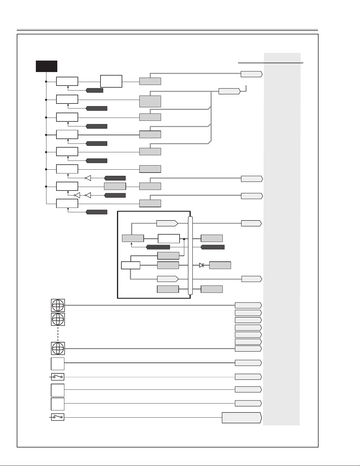
Chassis Description
PF_5V_PJ
FILTER_DET
PF_FN907
PF_FN903
PF_FN905&FN906
PF_FN904
PF_FN902
PF_FN901
PF_FN908
ERROR INFO.
DETECTION
LINE NAME
MAIN, 25V
MAIN, 9V
MAIN, S12V
FN901
FN902
FN908
AV, LAN
AV, AV
MAIN, FAN1
MAIN, FAN2
MAIN, FAN3
MAIN, FAN4
MAIN, FAN5
MAIN, FAN6
MAIN, FAN7
PJ-NET, 5V
ERR, FIL_DET
FILTER_COUNT
ERR, FIL_MTR
Network
Board
MOTOR
ROUND
SW1891
FILTER SW.
SHUTTER
SW
IC1899
PRESS_SENS
ERR, PRESSURE
PRESS
SENSOR
IC1802
SHUTTER_POS1_PIC1
SHUTTER_POS1_PIC1
ERR, SHUT_MTR
S16V
ON_25V
25V
Q7432
IC7431
Q7433
PF_25V
PNL15V_ON
S3.3V
HVDD
VVDD
IC3516
PF_GAM
SH15V_ON
15V_SHR
IC3511
SH15V_ON
15V_SHG
IC3531
SH15V_ON
15V_SHB
IC3551
IC_RESET
15V_LNS
IC6612
PF_9V
Q6613
IC_RESET
9V_LNS10VA
IC6606
PF_S12V
S12V
IC5542
Q6622Q6621
To: S6V line
LAN_POW_SW LAN_POW_SW
S3.3V_LAN S5V
S5V
5VDVI1
K21A
K10A
AV
D201
PF_LAN PF_LAN
PF_AV
PF_AV
1
22
80
5
14
27
Q2082
IC8341
S-6VS-5V
5VDVI1
S16V Line and others
-86-
LHD700 Service Manual
020-000423-02 Rev.1 (01-2013)
Page 89
Chassis Description
Error History Log
This projector provides the error history log function. To
check the logs, you need to enter the service mode and
select Group No. "220" and Item No. "0" to "49". The error
code is displayed on the Data column. The description of
the error code is listed on the table below.
* How to enter the service mode and select the group, item
and data value, see "Service Adjustment Menu Operation".
Error Error Code
Normal 0 -
1000
1001
1002
1003
1004
1005
1006
Power Failure
Temperature Error
Lamp Error
System Error 4000
Shutter Error 5000
Filter Error 6000 Filter clogged
1007
1008
1009
1010
1011
1012
1013
1014
1015
2000
2001 Sensor A fails measurement. (IC1816)
2100 Sensor B detects abnormal temperature. (IC1814)
2101 Sensor B fails measurement. (IC1814)
2102 Sensors B-A temperature error.
2200 Sensor C detects abnormal temperature. (IC1692)
2201
2202 Sensors C-A temperature error.
3000 Lamp1 fails on
3001 Lamp1 goes out
3002 Communication Error on Lamp1
Error Infomation
(See Powe Failure Detection System)
A
AV,
LAN
AV,
MAIN,
A
MAIN,
S
MAIN,
F-FPGA
MAIN, 5V
MAIN,
PIC
MAIN,
25V
KEY
MAIN,
MAIN,
GAMMA
MAIN,
9
MAIN,
S12
MAI
FAN1
N,
MAIN,
FAN
M
AIN, FA
MAIN,
FAN
Sensor A detects abnormal temperature. (IC1816)
Sensor C fails measurement. (IC1692)
GASW, CONFIG
FP
TER, ERROR
SHUT
V
D
I
STONE
V
V
2
N3
4
Group
No.
220 0
Error Code
1016
1017
1018
1019
1020
1021
1022
Item
No.
1
2
3
:
:
49
Data
(Error Code)
✻
✻
✻
✻
:
:
✻
<- Latest Error
Error Infomation
(See Powe Failure Detection System)
FAN
MAIN,
MAIN, FAN6
MAIN,
FAN7
ERR, PRESS
ERR, F
ERR, FIL_M
ERR, SHU
URE
I
L_DET
T
_MTR
5
TR
How to reset the Error History Log
1. Enter the Service Mode, and select Group No. "220" and Item No. "50".
2 The history log will be reset when the Data Value is set to "10". The value automatically returns to "0".
* How to enter the service mode and select the group, item and data value, see "Service Adjustment menu operation".
LHD700 Service Manual
020-000423-02 Rev.1 (01-2013)
-87-
Page 90
Chassis Description
Diagnosis of Power Failure with RS-232C port
This projector provides a function to get the error information of the projector by using the RS-232C serial port for the
power failure diagnosis.
The further error information of the power failure and fan failure can be found out by using this function.
Diagnosis procedure
1 Connect a RS-232C serial cross cable to CONTROL PORT on the projector and serial port on the PC.
2 Launch a communication software "Hyper terminal" provided with PC and setup the communication condition as
follows;
Baud rate : 9600 / 19200 bps
Parity check : none
Stop bit : 1
Flow control : none
Data bit : 8
3 Turn on the projector. Check that the LED shows a
power failure. (All the LEDs except LAMP LED are
blinking)
4 Type a diagnosis command of the power failure “CR
ALLPFAIL” and press a "ENTER" key within 1 second
on the command window of the software.
The error information will be listed on the window as
the right.
Check the status column. If “NG” is listed, the power
failure occurs on its signal line (Power Line Name). In
case of the right table, this error information means that
the power failure occurs on the 3.3VAD power supply
on the AD circuit on the main board. Check if the parts
connected to 3.3VAD power supply line are defective.
Also the error information may be listed multiple as the
below;
In the above case, 2 kinds of causes are considered.
One is the power failure occurs on the multiple places
at the same time, other is a power failure affects multiple power supply lines even if the failure occurs on the
single place.
In the first case, Check if the parts connected to the multiple power supply lines are defective. In the later case,
determine a failure point referring to the power supply
flow chart on previous page. Basically, if the power failure occurs on the upper side of power supply, the power
failure is also detected on lower side of power supply
frequently. If the failure occurs on the lower side of power supply, it is lightly affected to the upper side of the power
supply. In the above case, because the failure occurs on the S4.3V1 power supply on the main board, the failure is
also detected on the 3.3VAD and S3.3VSI power supply on the AD and SI (HDMI) circuit on the main board.
CR ALLPFAIL
000 AV, AV OK
000 AV, LAN OK
000 MAIN, AD NG
000 MAIN, SI NG
000 MAIN, F-FPGA OK
000 PJ-NET, 5V OK
000 MAIN, PIC OK
........ ............... ......... ......
CR ALLPFAIL
000 AV, AV OK
000 AV, LAN OK
000 MAIN, AD NG
000 MAIN, SI NG
000 MAIN, F-FPGA OK
000 PJ-NET, 5V OK
000 MAIN, PIC OK
........ ............... ......... ......
Error Information
(Signal Name)
Status
Error
Error
* See "Power Failure Detection System" for further description of the Error Information.
-88-
LHD700 Service Manual
020-000423-02 Rev.1 (01-2013)
Page 91
Chassis Description
Serial Control Interface
This projector provides a function to control and monitor the projector's operations by using the RS-232C serial port.
Operation
Connect a RS-232C serial cross cable to CONTROL PORT on the projector and serial port on the PC.
1
2 Launch a communication software "Hyper terminal" provided with PC and setup the communication condition as
follows;
Note: The default of the baud rate is set to 19200 bps. If an error occurs in
the communication, change the serial port and the communication
speed (baud rate).
3 Type the command for controlling the projector and then enter the "En-
ter" key within 1 second.
Example
When you want to change the input to INPUT 2, Type 'C' '0' '6' 'Enter'.
Note: Enter with ASCII 64-byte capital characters and one-byte characters.
Functional Execution Command
Format
The command is sent from PC to the projector with the format below;
'C' [Command] 'CR'
Command: two characters (refer to the command table below.
-The projector decodes the command and returns the 'ACK' with the format below;
'ACK' 'CR'
-When the projector can not decode the command, it returns with format below.
‘?’ ‘CR’
Baud rate : 9600 / 19200 bps
Parity check : none
Stop bit : 1
Flow control : none
Data bit : 8
Command Function
C00 Turn the projector ON
C01 Turn the projector OFF (immediately OFF)
C02 Turn the projector OFF
C05 Select Input 1
C06 Select Input 2
C07 Select Input 3
C08 Select Network
C0D Video mute ON
C0E Video mute OFF
C0F Screen Normal Size
C10 Screen Full Size
C1C Menu ON
C1D Menu OFF
C20 Brightness UP
C21 Brightness DOWN
C23 Select Input 2 Video
C24 Select Input 2 Y, Pb/Cb,Pr/Cr
C25 Select Input 2 RGB
C28 Direct on ON
C29 Direct on OFF
C33 Select Input 3 Video
C34 Select Input 3 S-video
C35 Select Input 3 Y, Pb/Cb,Pr/Cr
Command Function
C3A Pointer RIGHT
C3B Pointer LEFT
C3C Pointer UP
C3D Pointer DOWN
C3F Enter
C46 Zoom DOWN
C47 Zoom UP
C4A Focus DOWN
C4B Focus UP
C4F Select Input 1 HDMI
C50 Select Input 1 Analog RGB
C51 Select Input 1 SCART
C52 Select Input 1 DVI (PC Digital)
C53 Select Input 1 DVI (AV HDCP)
C5D Lens shift UP
C5E Lens shift DOWN
C5F Lens shift LEFT
C60 Lens shift RIGHT
C89 Auto PC Adj.
C8E Keystone UP
C8F Keystone DOWN
C90 Keystone RIGHT
C91 Keystone LEFT
LHD700 Service Manual
020-000423-02 Rev.1 (01-2013)
-89-
Page 92
Chassis Description
Status Read Command
Format
The command is sent from PC to the projector with the format below;
'CR' [Command] 'CR'
Command: one character (refer to the command table below.
The projector decodes the command and returns the 'Character string' with the format below;
Command Function Projector Return Projector status
00 Power On
80 Stand-by mode
40 Countdown
20 Cooling down
10 Power Malfunction
28 Cooling down at the temperature anomaly
CR0 Status Read
CR6 Temperature Read S1 S2 S3
24 Cooling down at Power Management mode
04 Power Management mode after Cooling down
21 Cooling down after the projector is turned off when the lamps are out.
81 Stand-by mode after Cooling down when the lamps are out.
88 Stand-by mode after Cooling down at the temperature anomaly.
2C
8C Stand-by mode after cooling down by the shutter management function.
? Communication failure
Cooling down when the projector is turned off by the shutter management
function.
S1 = Temperature at Sensor 1 (Temp A) (˚C)
S2 = Temperature at Sensor 2 (Temp B) (˚C)
S3 = Temperature at Sensor 3 (Temp C) (˚C)
(ex.) S1 = 12.3˚C, S2 = 23.4˚C, S3 = 34.5˚C
--> The projector displays “12.3 23.4 34.5”
( For each sensor, two digit and the tenth place numbers are displayed
with a space between each temperature.)
The tables show the typical command lists for controlling the projector. Please consult your local dealer for
further information of other commands.
-90-
LHD700 Service Manual
020-000423-02 Rev.1 (01-2013)
Page 93

Control Port Functions
System Control I/O Port Functions (PW392, IC301)
PIN P ORT SI GNAL FUNCT IOM I/O NOTE
A18 HS OUT H SYNC Inpu t I
A19 LEN S_L_ POSI_E X Lens S hift L Dete ct Input I
A20 PW_SDA3 IIC Bus 3 I/ O
A25 PF_9V Power Fail I nput 9V I L: Erro r
A27 KEY11 Keypad Inpu t I
A28 KEY31 Keypad Inpu t I
A29 KEY03 Keypad Inpu t I
B18 I N0HS H SYN C Input I
B19 L ENS_R_POSI_EX Lens Sh ift R Detec t Input I
B20 PW_SCL3 IIC Bus 3 I/O
B22 FAN_DRIV E_CPU Fan Contro l Switch Output O
B23 PF_AD Power Fail IN put AD I L: Erro r
B24 DVI_DDC_SW_CPU DVI DDC Swit ch output O
B27 KEY21 Keypad Input I
B28 KEY02 Keypad Inpu t I
B29 POWER ON Keypad Input I
C18 IN 0VS V Sync In put I
C19 LEN S_BOT_EX Lens Shif t Bottom D etect Inpu t I
C23 PF_SI Power Fail Inp ut SI I L: Error
C24 D SUB_DD C_SW_CPU DDC Switch Co ntrol (DSUB) O
C25 SW_1.8VGAM_EX SW_1.8V Switch output O H: On
C26 SW_1VGAM_ EX SW_1VGAM Switch o utput O H: On
C27 KEY01 Key pad Input I
C28 LAMP_SWIN_E X LAMP D rive Switc h Output O H: O n
C30 PFC_SW_EX Fan Cont rol Switch O utput O H: O n
D19 LEN S_TOP_EX L ens Shift Top Det ect Input I
D22 FILTER_DET Fil ter Detect I nput I
D24 PF_AV Power Fail I nput AV I L: Error
D25 SW_2.5VGAM _EX SW_2.5V D rive Signa l Output O H : On
D26 SW_1.8V_KS_EX SW_1.8V Drive Si gnal Output(KS) O H: On
D27 SW_2.5V_KS_ EX SW_ 2.5V Drive Signal Out put( KS) O H : On
D28 PF_PIC Power Fail Input PIC I L : Error
D29 SW_3.3V_KS_ EX SW_3.3V Drive Sig nal Output(KS ) O H: On
D30 PF_FN908 Power Fai l Input FN9 08 I L: Er ror
E2 RST Res et IC I
E25 SW_3.3VGAM _EX SW_3.3V D rive Signa l Output H : On O H: On
E26 FILTER_LED Filter L ED Drive Output O H: O n
E27 SHUTTER_LED Shut ter LED Drive O utput O H: On
E28 LAMP_LED Lamp LED Dr ive Output O H: On
E29 TEMP_LED War ning LED Dri ve Output O H: On
E30 LAMP_REP_LED Lamp Rep lace LED Dri ve output O H : On
F29 POWER_ LED Power LED Drive Out put O H : On
F30 POWER_SW_LAN Lan Power Sw itch Outp ut O H: On
G2 ASPECT2 Aspect In 2 I
G3 ASPECT1 Aspect In 1 I
G4 ASPECT0 Aspect In 0 I
G29 O N_SI_ SW_CPU SI Power Switch Ou tput O H: On
J1 IN_VIDEO2 Comp osite Vid eo Signal Input 2 I
J26 PIC_I2C_SW IIC D ata Switch f or PIC O
J27 YE _MUTE_ SW YE MUTE SW O utput O
K1 S_C S -Video C Sig nal I
K3 S _Y S-Vide o Y Signal I
K26 ZOOM-_ EX Zoom- Dr ive Output O
K28 PF_5V_PJ Power Fail In put Networ k Box I L: Error
K29 FOCUS +_EX Focus+ Drive Outp ut O
K30 FOCUS-_ EX Fo cus- Drive O utput O
L1 I N_3_VIDEO Compo site Video Input 3 I
L26 PW_S DA0 IIC Bu s 0 I/ O
L27 PW_SC L0 IIC Bus 0 I/ O
L30 ZOOM +_EX Zoom + Drive Outp ut O
M26 RX D_MCI Ser ial RXD for MCI I/ O
M27 TX D_MCI Serial T XD for MCI I/ O
M29 PF_FN9 05&F N906 Power Fai l Input FN9 05, FN90 6 I L: Erro r
M30 PF_FN9 07 Power Fail In put FN907 I L: Erro r
N1 B_ IN1_PW B IN1 Inpu t I
N3 SCAR T_CV Co mposite V ideo Input S CART I
P1/P2 G_IN1_P W G IN1 Input I
P3 B _IN1_PW B IN1 In put I
R1/T1 Y_IN3_PW Y IN3 Input I
R2 CB _IN3_ PW CB IN 3 Input I
LHD700 Service Manual
020-000423-02 Rev.1 (01-2013)
-91-
Page 94

Control Port Functions
PIN P ORT SI GNAL FUNCT IOM I/O NOTE
T1 C R_IN3 _PW CR IN3 i nput I
U1/U2 G _IN2_ PW G IN 2 Input I
U3 B_ IN2_PW B IN2 I nput I
V2 R _IN2_ PW R IN2 Input I
AA1 INPUT2_VS_EX V-Sync In put2 I
AA2 INPUT1_VS_EX V-Syn c Input1 I
AA3 I NPUT1_HS_EX H- Sync Input1 I
AA4 I NPUT2_H S_EX H- Sync Input12 I
AG10 FILTER_COUN T Filter Scro ll Counter I nput I
AG12 EX_PW_UART UART for S Port I /O
AG17 PW_DCLK Cl ock I
AG18 PW_DHS H Sync Input I
AH9 NM I_RST Push switc h I
AH10 PF_S12V Power Fail Inp ut S12V I L: Erro r
AH11 PW_R /C Remote Control Signal Inpu t I
AH12 PW_EX_UART UART for S Por t I/ O
AH18 PW_DVS V Sync Input I
AH21 PF_KS Power Fail Input KS I L: Error
AH22 PRES S_SENSE Pressu re Sensor In put I
AJ20 PF_GAM Power Fail I nput GAM I L: Error
AJ22 LENS_C_POSI _EX Lens Pos ition C Inp ut I
AJ24 TRM 2 RGB In Terminate 2 O
AK20 PF_25V Power Fail Input 25V I L: Er ror
AK21 W INDS_SEN S Wi nd Sensor In put I
AK22 PF_FRT Powe r Fail Input Fron t FPGA I L: Erro r
AK23 OUT_SW Monitor Out put Switc h O
AK24 T RM1 RGB Termin ate 1 O
I/O Expander (TE7783, IC4801)
PIN PORT SIGNAL FUNCTION I/O NOTE
2 P1 BUFFER_ SW1 Buffer SW Ou tput O
3 P2 NET_SW_PW PJNET Switc h Output O
4 P3 IC_RES ET_CPU Rese t Output for M otor Drive Ics O H: O n
5 P4 F_MOTOR_SW Filter M otor Drive Sw itch O H: On
6 P5 LENS_ LR_SW Len s Shift L /R Detec t Input I
7 P6 LENS_UD_SW Lens Shift U /D Dete ct Input I
8 P7 PJ_UPDATE PJNET Fi rmware update O
9 P8 NET_H /L PJNET O
49 P 22 PROG_ B_FRT SW_FPGA C onfig O
50 P23 DDC_ SCL IIC CLK fo r DDC I /O
51 P 24 DDC_SDA IIC Data for DDC I /O
52 P 25 GAMMA _SCL IIC CLK for G amma IC I O
53 P26 GAM MA_SD L IIC Dat a for Gamma IC IO
54 P27 USB B_VBUS IO USB
55 P28 USB B_D+ IO USB
61 AIN [1] PF_FN901 Power Fail Input FN 901 I L: Err or
62 AIN [2] PF_FN902 Power Fail Input F N902 I L: Er ror
63 AIN [3] PF_FN 903 Po wer Fail Input FN 903 I L: Error
64 AIN [4] PF_FN904 Power Fail Input FN904 I L: Er ror
65 AIN [5] ACCELE_S ENS1 G-Sen sor1 I
66 AIN [6] ACCELE_TEMP1 G- Sensor1 I
67 AIN [7] ACCELE_S ENS2 G-Sensor2 I
68 AIN [8] ACCELE_TEMP2 G- Sensor2 I
72 P31 I/O_PJ_UART UART for PJNET IO UART
73 P 32 PJ_I/ O_UART UART f or PJNET I O UART
74 P3 3 MOUSE_TXD PJNET Mouse IO UART
76 P3 5 LENS_L R_PWM Lens Shift L/ R Control PWM O PWM
77 P 36 LENS_U D_PWM Lens Shi ft U/ D Control P WM O PWM
78 P 37 LENS_LR_SW Len s Shift L /R Switch O PWM
79 P 38 LENS_UD _SW Lens Shift U /D Swit ch O
81 DMINU S USBB_ D- USB IO
82 DPLUS US BB_D + USB IO
91 P11 SCLK _FRT SW FPGA Co nfig O 3-Wire
92 P12 SDAT_FRT SW FPGA Con fig O 3-Wire
94 P14 BOX_ SW PJNET I
97 P15 W_RC_ SW Wired R emote Cont rol Detect I nput I
98 P16 SILEN T I
99 P17 PF_LAN Power Fail I nput LAN I L: Error
100 P18 D ONE_FRT SW FPGA Config O
-92-
LHD700 Service Manual
020-000423-02 Rev.1 (01-2013)
Page 95

Control Port Functions
FPGA (XC3S50A, IC5201)
PIN PORT SIG NAL FUNC TION I/O NOTE
3 A3 -BNC/RCA BNC/RCA Switch Output O
4 A4 -IN1/IN2 IN1/IN2 Switch Output O
13 A13 HSOUT H-Sync Input I
14 A14 FRT_HS_OUT H-Sync Output for FRT O
204 J12 IN0VS V Sync Output O
171 J13 IN0HS H Sync Output O
131 K14 CG_HSYNC H-Sync Input from AD I
82 K15 CG_VSYNC V-Sync Input from AD I
232 L10 SI_HS H-SYnc Input from SI I
139 P10 SI_VS V-Sync Input from SI I
IIC Bus D/A Converter (M62393FP Fan Control, IC7801)
Pin No. Function N ame Func tion Pol .
1 Reset Inp ut I
2 PW_SCLO_S 5V IIC bus CLK I
3 PW_SDA0_S 5V IIC bus Data I /O
4 FAN_CONT6 FAN_FN9 01 Control Volt age (Pane l Cooling Fan ) AO
5 FAN_CONT5 FAN_FN9 02 Control Vol tage (Pan el Coolin g Fan) AO
6 FAN DRIVE B FAN_FN 903 Drive AO
7 FAN_CONT 7 FAN_FN 908 Contr ol Voltage ( PBS Coolin g Fan) AO
8 GND -
9 GND -
10 GND -
11 GND -
12 FAN_CONT4 FAN_ FN904 C ontrol Volta ge (Lam p Cooling Fan ) AO
13 FAN_CONT3
14 FAN_CO NT2 FAN_ FN903 Co ntrol Voltag e (Lamp C ooling Fan ) AO
15 FAN_C ONT1 FAN_ FN907 Control Voltag e (Power Coo ling Fan) AO
16 Power fo r Output Bu ffer (4.5V ~ 5. 5V) -
17 Power Su pply +5V ±10% -
18 Slave A ddress Set ting Pin2 ( 5V) I
19 Slave A ddress Set ting Pin1 (5V ) I
20 Sl ave Address Se tting Pin 0 (5V) I
FAN_FN9 05& FN906 Co ntrol Voltag e (Set Exh aust
Fans small)
AO
Stand -by Power On
→
→
→
0: FAN Max ~ 255: FAN Min
→
0: FAN Max ~ 255: FAN Min
→
255: ON 0: OFF
→
(Ope n)
→
→
→
→
→
0: FAN Max ~ 255: FAN Min
→
0: FAN Max ~ 255: FAN Min
→
0: FAN Max ~ 255: FAN Min
→
0: FAN Max ~ 255: FAN Min
→
→
→
H
→
H
→
H
→
Action
LHD700 Service Manual
020-000423-02 Rev.1 (01-2013)
-93-
Page 96

IC Block Diagrams
● AD8183 <Amp-SW, IC2001, IC5001>
● BA6287 <Motor Drive Focus, Zoom, Shutter IC5501, IC5521, IC5561>
-94-
LHD700 Service Manual
020-000423-02 Rev.1 (01-2013)
Page 97
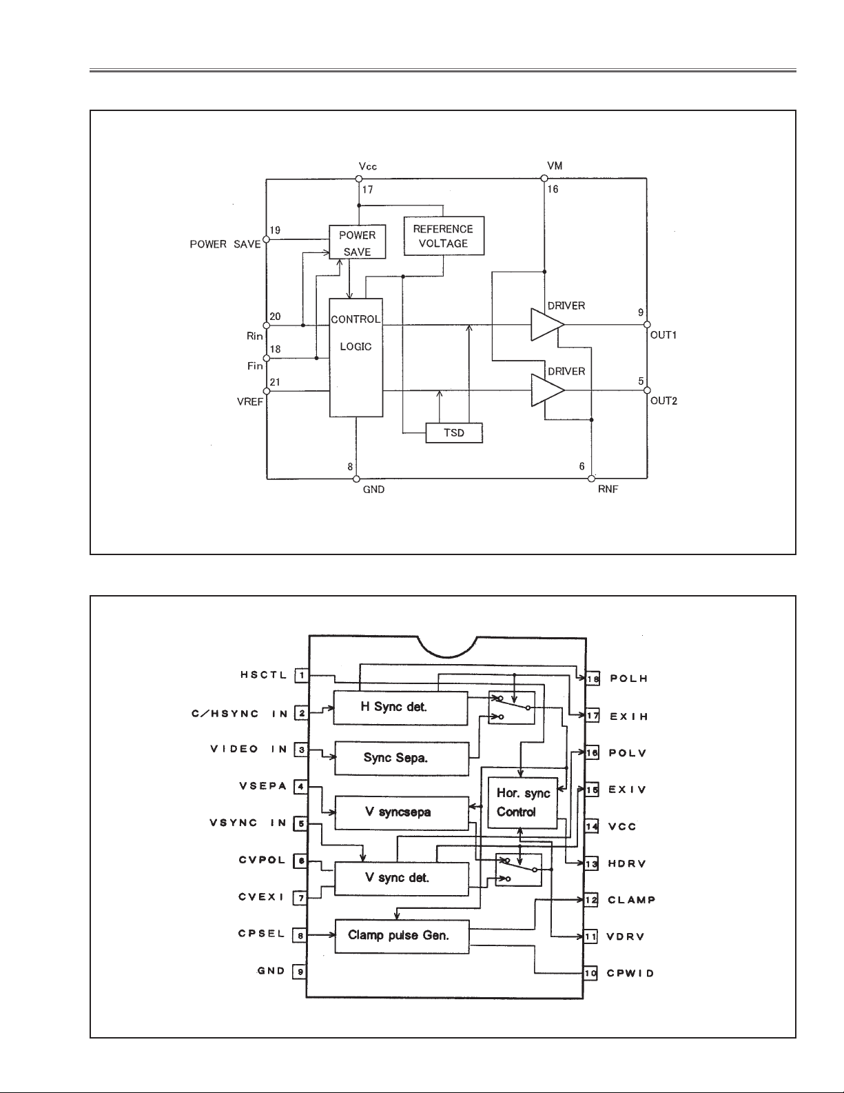
IC Block Diagrams
● BA6920 <Motor Drive Lens Shift Up/Down, Left/Right, IC6501, IC6521>
● BA7078 <Sync Separator, 1011>
LHD700 Service Manual
020-000423-02 Rev.1 (01-2013)
-95-
Page 98

IC Block Diagrams
● CXA7010R <S&H, IC501, IC551, IC1501, IC1551, IC2501, IC2551>
● CXD3550 <Digital Gamma Shift & LCD Driver, IC401>
-96-
LHD700 Service Manual
020-000423-02 Rev.1 (01-2013)
Page 99
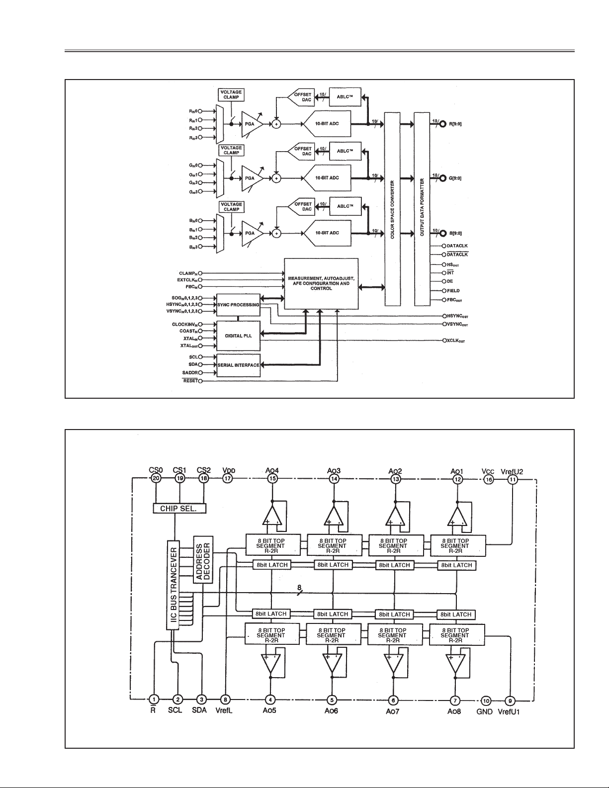
IC Block Diagrams
● ISL51002 <A/D Converter, IC2201>
● M62393 <DAC, IC7801>
LHD700 Service Manual
020-000423-02 Rev.1 (01-2013)
-97-
Page 100
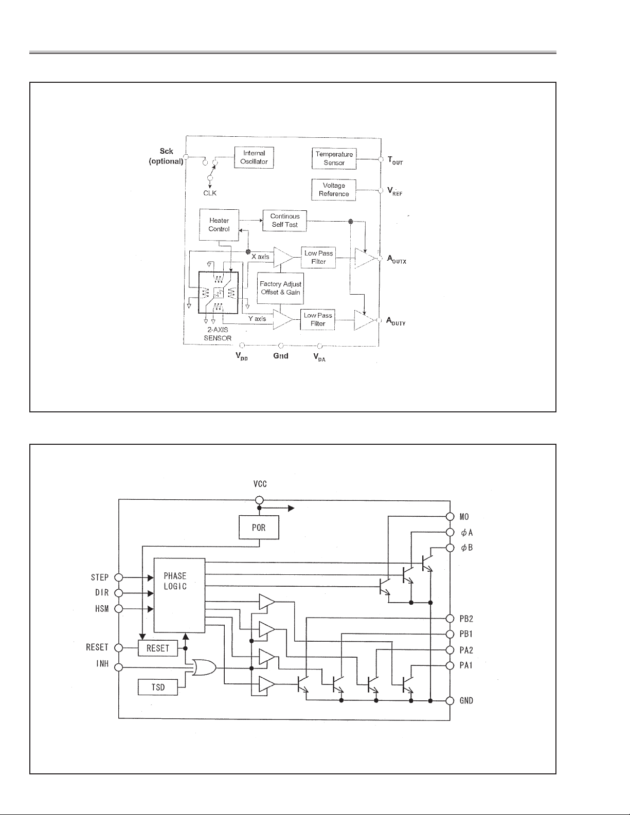
IC Block Diagrams
● MXA2500 <Dual Axis Accelerometer, IC1881, IC1882>
● NJM2671 <Motor Controller, IC5541>
-98-
LHD700 Service Manual
020-000423-02 Rev.1 (01-2013)
 Loading...