

Page 1
• This PDF catalog is downloaded from the website of Murata Manufacturing co., ltd. Therefore, it’s specifications are subject to change or our products in it may be discontinued without advance notice. Please check with our
!Note
sales representatives or product engineers before ordering.
• This PDF catalog has only typical specifications because there is no space for detailed specifications. Therefore, please approve our product specifications or transact the approval sheet for product specifications before ordering.
Chip Monolithic
Ceramic Capacitors
C02E.pdf
09.9.18
Cat.No.C02E-15
Page 2
• This PDF catalog is downloaded from the website of Murata Manufacturing co., ltd. Therefore, it’s specifications are subject to change or our products in it may be discontinued without advance notice. Please check with our
!Note
• Please read rating and !CAUTION (for storage, operating, rating, soldering, mounting and handling) in this catalog to prevent smoking and/or burning, etc.
!Note
sales representatives or product engineers before ordering.
• This catalog has only typical specifications because there is no space for detailed specifications. Therefore, please approve our product specifications or transact the approval sheet for product specifications before ordering.
• This PDF catalog has only typical specifications because there is no space for detailed specifications. Therefore, please approve our product specifications or transact the approval sheet for product specifications before ordering.
CONTENTS
Part Numbering 2
Selection Guide 7
1
for General Purpose GRM Series 8
1
Specifications and Test Methods 51
GRM Series Data 60
2
Capacitor Array GNM Series 63
2
Specifications and Test Methods 68
3
Low ESL LLL/LLA/LLM Series 74
C02E.pdf
09.9.18
3
Specifications and Test Methods 81
4
High-Q Type GJM Series 85
4
Specifications and Test Methods 95
5
High Frequency GQM Series 98
5
Specifications and Test Methods 105
GQM Series Data 108
6
High Frequency Type ERB Series 109
6
Specifications and Test Methods 116
ERB Series Data 119
7
Monolithic Microchip GMA Series 121
7
Specifications and Test Methods 123
8
for Bonding GMD Series 127
8
Specifications and Test Methods 132
Package 136
!Caution 140
Notice 152
Reference Data 159
9
Medium Voltage Low Dissipation Factor 166
10
Medium Voltage High Capacitance for General Use 171
11
Only for LCD Backlight Inverter Circuit 176
12
Only for Information Devices 179
Page 3
• This PDF catalog is downloaded from the website of Murata Manufacturing co., ltd. Therefore, it’s specifications are subject to change or our products in it may be discontinued without advance notice. Please check with our
!Note
• Please read rating and !CAUTION (for storage, operating, rating, soldering, mounting and handling) in this catalog to prevent smoking and/or burning, etc.
!Note
sales representatives or product engineers before ordering.
• This catalog has only typical specifications because there is no space for detailed specifications. Therefore, please approve our product specifications or transact the approval sheet for product specifications before ordering.
• This PDF catalog has only typical specifications because there is no space for detailed specifications. Therefore, please approve our product specifications or transact the approval sheet for product specifications before ordering.
13
Only for Camera Flash Circuit 183
C02E.pdf
09.9.18
1
2
14
AC250V (r.m.s.) Type (Which Meet Japanese Law) 187
15
Safety Standard Recognized Type GC (UL, IEC60384-14 Class X1/Y2) 191
16
Safety Standard Recognized Type GD (IEC60384-14 Class Y3) 192
17
Safety Standard Recognized Type GF (IEC60384-14 Class Y2, X1/Y2) 193
18
Safety Standard Recognized Type GB (IEC60384-14 Class X2) 195
GA3 Series Specifications and Test Methods 196
GRM/GR4/GR7/GA2/GA3 Series Data (Typical Example) 200
Package 203
!Caution 206
Notice 214
ISO 9001 Certifications 217
14
Please refer to "Specifications and Test Methods" at the end of each chapter of – .
9
3
4
5
6
7
8
9
10
for EU RoHS Compliant
• All the products in this catalog comply with EU RoHS.
• EU RoHS is "the European Directive 2002/95/EC on the Restriction of the Use
of Certain Hazardous Substances in Electrical and Electronic Equipment".
• For more details, please refer to our website 'Murata's Approach for EU RoHS'
(http://www.murata.com/info/rohs.html).
11
12
13
14
15
16
17
18
Please check MURATA home page (http://www.murata.com/index.html) in case you can not find the part number on the catalog.
Page 4
• This PDF catalog is downloaded from the website of Murata Manufacturing co., ltd. Therefore, it’s specifications are subject to change or our products in it may be discontinued without advance notice. Please check with our
!Note
• Please read rating and !CAUTION (for storage, operating, rating, soldering, mounting and handling) in this catalog to prevent smoking and/or burning, etc.
!Note
sales representatives or product engineers before ordering.
• This catalog has only typical specifications because there is no space for detailed specifications. Therefore, please approve our product specifications or transact the approval sheet for product specifications before ordering.
• This PDF catalog has only typical specifications because there is no space for detailed specifications. Therefore, please approve our product specifications or transact the approval sheet for product specifications before ordering.
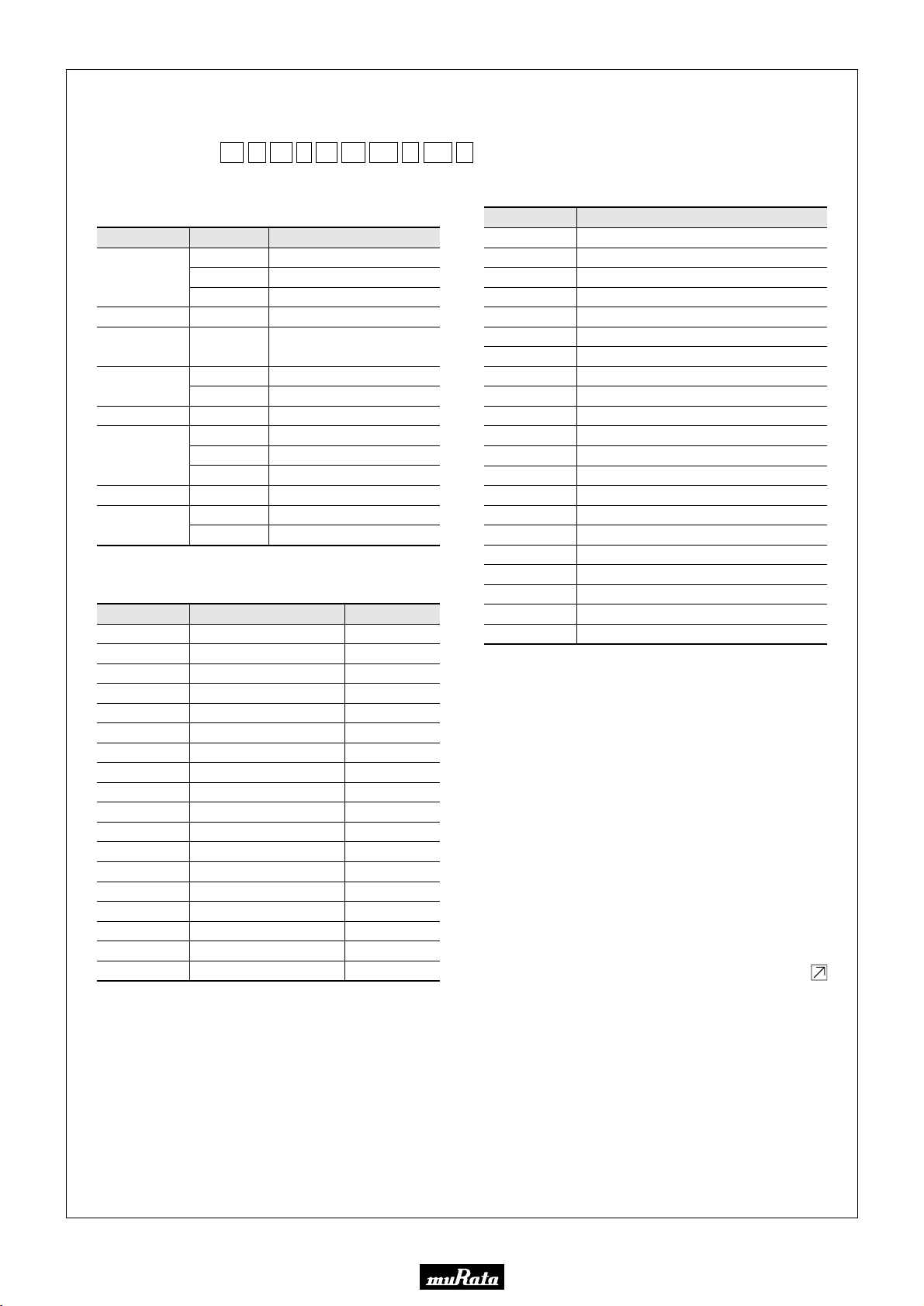
o Part Numberingo Part Numbering
Chip Monolithic Ceramic Capacitors
C02E.pdf
09.9.18
(Part Number)
GR
q
M
e18r8tB1y1Hu
w
qProduct ID
wSeries
Product ID Code Series
Tin Plated Layer
Only for Information Devices / Tip & Ring
Only for Camera Flash Circuit
High Frequency Type
High Frequency for
Flow/Reflow Soldering
Monolithic Microchip
for Bonding
Capacitor Array
Low ESL Wide Width Type
Eight-termination Low ESL Type
Ten-termination Low ESL Type
High Frequency Low Loss Type
for AC250V (r.m.s.)
Safety Standard Recognized Type
GR
ER
GQ
GM
GN
LL
GJ
GA
M
4
7
B
M
A
D
M
L
A
M
M
2
3
eDimension (LgW)
Code
02
03
05
08
0D
0M
11
15
18
1M
21
22
31
32
42
43
52
55
Dimension (LgW)
0.4g0.2mm
0.6g0.3mm
0.5g0.5mm
0.8g0.8mm
0.38g0.38mm
0.9g0.6mm
1.25g1.0mm
1.0g0.5mm
1.6g0.8mm
1.37g1.0mm
2.0g1.25mm
2.8g2.8mm
3.2g1.6mm
3.2g2.5mm
4.5g2.0mm
4.5g3.2mm
5.7g2.8mm
5.7g5.0mm
102iKoA01
EIA
01005
0201
0202
0303
015015
0302
0504
0402
0603
0504
0805
1111
1206
1210
1808
1812
2211
2220
D
!0
rDimension (T)
Code
2
2
3
4
5
6
7
8
9
A
B
C
D
E
F
M
N
Q
R
S
X
With the array type GNM series, "Dimension(T)" indicates the number of
elements.
Depends on individual standards.
Dimension (T)
0.2mm
2-elements (Array Type)
0.3mm
4-elements (Array Type)
0.5mm
0.6mm
0.7mm
0.8mm
0.85mm
1.0mm
1.25mm
1.6mm
2.0mm
2.5mm
3.2mm
1.15mm
1.35mm
1.5mm
1.8mm
2.8mm
Continued on the following page.
Please check MURATA home page (http://www.murata.com/index.html) in case you can not find the part number on the catalog.
2
Page 5
• This PDF catalog is downloaded from the website of Murata Manufacturing co., ltd. Therefore, it’s specifications are subject to change or our products in it may be discontinued without advance notice. Please check with our
!Note
• Please read rating and !CAUTION (for storage, operating, rating, soldering, mounting and handling) in this catalog to prevent smoking and/or burning, etc.
!Note
sales representatives or product engineers before ordering.
• This catalog has only typical specifications because there is no space for detailed specifications. Therefore, please approve our product specifications or transact the approval sheet for product specifications before ordering.
• This PDF catalog has only typical specifications because there is no space for detailed specifications. Therefore, please approve our product specifications or transact the approval sheet for product specifications before ordering.
Continued from the preceding page.
tTemperature Characteristics
Temperature Characteristic Codes Temperature Characteristics
Code
1X
2C
2P
2R
2S
2T
3C
3P
3R
3S
3T
3U
4C
5C
5G
6C
6P
6R
6S
6T
7U
B1
B3
C7
C8
Public STD Code
SL *1
CH *1
PH *1
RH *1
SH *1
TH *1
CJ *1
PJ *1
RJ *1
SJ *1
TJ *1
UJ *1
CK *1
C0G *1
X8G *1
C0H *1
P2H *1
R2H *1
S2H *1
T2H *1
U2J *1
B *2
B
X7S
X6S
JIS
JIS
JIS
JIS
JIS
JIS
JIS
JIS
JIS
JIS
JIS
JIS
JIS
EIA
EIA
EIA
EIA
EIA
EIA
EIA
EIA
JIS
JIS
EIA
EIA
Reference
Temperature
20°C
20°C
20°C
20°C
20°C
20°C
20°C
20°C
20°C
20°C
20°C
20°C
20°C
25°C
25°C
25°C
25°C
25°C
25°C
25°C
25°C
20°C
20°C
25°C
25°C
Temperature
Range
20 to 85°C
20 to 125°C
20 to 85°C
20 to 85°C
20 to 85°C
20 to 85°C
20 to 125°C
20 to 85°C
20 to 85°C
20 to 85°C
20 to 85°C
20 to 85°C
20 to 125°C
25 to 125°C
25 to 150°C
25 to 125°C
25 to 85°C
25 to 85°C
25 to 85°C
25 to 85°C
25 to 125°C *6
-25 to 85°C
-25 to 85°C
-55 to 125°C
-55 to 105°C
Capacitance Change or
Temperature Coefficient
+350 to -1000ppm/°C
0±60ppm/°C
-150±60ppm/°C
-220±60ppm/°C
-330±60ppm/°C
-470±60ppm/°C
0±120ppm/°C
-150±120ppm/°C
-220±120ppm/°C
-330±120ppm/°C
-470±120ppm/°C
-750±120ppm/°C
0±250ppm/°C
0±30ppm/°C
0±30ppm/°C
0±60ppm/°C
-150±60ppm/°C
-220±60ppm/°C
-330±60ppm/°C
-470±60ppm/°C
-750±120ppm/°C
±10%
±10%
±22%
±22%
Operating
Temperature Range
-55 to 125°C
-55 to 125°C
-25 to 85°C
-25 to 85°C
-25 to 85°C
-25 to 85°C
-55 to 125°C
-25 to 85°C
-25 to 85°C
-25 to 85°C
-25 to 85°C
-25 to 85°C
-55 to 125°C
-55 to 125°C
-55 to 150°C
-55 to 125°C
-55 to 125°C
-55 to 125°C
-55 to 125°C
-55 to 125°C
-55 to 125°C
-25 to 85°C
-25 to 85°C
-55 to 125°C
-55 to 105°C
-55 to 125°C +22, -33%X7TD7 -55 to 125°C25°CEIA
-55 to 105°C +22, -33%X6TD8 -55 to 105°C25°CEIA
-55 to 125°C +22, -56%X7UE7 -55 to 125°C25°CEIA
F1
F5
L8
R1
R3
R6
R7
R9
W0
*1 Please refer to table for Capacitance Change under reference temperature.
*2 Capacitance change is specified with 50% rated voltage applied.
*3 Murata Temperature Characteristic Code.
*4 Apply DC350V bias.
*5 No DC bias.
*6 Rated Voltage 100Vdc max : 25 to 85°C
F *2
Y5V
X8L
R *2
R
X5R
X7R
X8R
-
JIS
EIA
*3
JIS
JIS
EIA
EIA
EIA
-
20°C
25°C
25°C
20°C
20°C
25°C
25°C
25°C
25°C
-25 to 85°C
-30 to 85°C
-55 to 150°C
-55 to 125°C
-55 to 125°C
-55 to 85°C
-55 to 125°C
-55 to 150°C
-55 to 125°C
+30, -80%
+22, -82%
+15, -40%
±15%
±15%
±15%
±15%
±15%
±10% *4
+22, -33% *5
-25 to 85°C
-30 to 85°C
-55 to 150°C
-55 to 125°C
-55 to 125°C
-55 to 85°C
-55 to 125°C
-55 to 150°C
-55 to 125°C
Continued on the following page.
C02E.pdf
09.9.18
Please check MURATA home page (http://www.murata.com/index.html) in case you can not find the part number on the catalog.
3
Page 6
• This PDF catalog is downloaded from the website of Murata Manufacturing co., ltd. Therefore, it’s specifications are subject to change or our products in it may be discontinued without advance notice. Please check with our
!Note
• Please read rating and !CAUTION (for storage, operating, rating, soldering, mounting and handling) in this catalog to prevent smoking and/or burning, etc.
!Note
sales representatives or product engineers before ordering.
• This catalog has only typical specifications because there is no space for detailed specifications. Therefore, please approve our product specifications or transact the approval sheet for product specifications before ordering.
• This PDF catalog has only typical specifications because there is no space for detailed specifications. Therefore, please approve our product specifications or transact the approval sheet for product specifications before ordering.
Continued from the preceding page.
oCapacitance Change from each temperature
JIS Code
Capacitance Change from 20°C (%)
Murata Code
–55°C –25°C –10°C
Max. Min. Max. Min. Max. Min.
1X – – – – – –
2C 0.82 –0.45 0.49 –0.27 0.33 –0.18
2P – – 1.32 0.41 0.88 0.27
2R – – 1.70 0.72 1.13 0.48
2S – – 2.30 1.22 1.54 0.81
2T – – 3.07 1.85 2.05 1.23
3C 1.37 –0.90 0.82 –0.54 0.55 –0.36
3P – – 1.65 0.14 1.10 0.09
3R – – 2.03 0.45 1.35 0.30
3S – – 2.63 0.95 1.76 0.63
3T – – 3.40 1.58 2.27 1.05
3U – – 4.94 2.84 3.29 1.89
4C 2.56 –1.88 1.54 –1.13 1.02 –0.75
C02E.pdf
09.9.18
EIA Code
Capacitance Change from 25°C (%)
Murata Code
–55°C –30°C –10°C
Max. Min. Max. Min. Max. Min.
5C/5G 0.58 –0.24 0.40 –0.17 0.25 –0.11
6C 0.87 –0.48 0.59 –0.33 0.38 –0.21
6P 2.33 0.72 1.61 0.50 1.02 0.32
6R 3.02 1.28 2.08 0.88 1.32 0.56
6S 4.09 2.16 2.81 1.49 1.79 0.95
6T 5.46 3.28 3.75 2.26 2.39 1.44
7U 8.78 5.04 6.04 3.47 3.84 2.21
Continued on the following page.
Please check MURATA home page (http://www.murata.com/index.html) in case you can not find the part number on the catalog.
4
Page 7
• This PDF catalog is downloaded from the website of Murata Manufacturing co., ltd. Therefore, it’s specifications are subject to change or our products in it may be discontinued without advance notice. Please check with our
!Note
• Please read rating and !CAUTION (for storage, operating, rating, soldering, mounting and handling) in this catalog to prevent smoking and/or burning, etc.
!Note
sales representatives or product engineers before ordering.
• This catalog has only typical specifications because there is no space for detailed specifications. Therefore, please approve our product specifications or transact the approval sheet for product specifications before ordering.
• This PDF catalog has only typical specifications because there is no space for detailed specifications. Therefore, please approve our product specifications or transact the approval sheet for product specifications before ordering.
Continued from the preceding page.
yRated Voltage
Code Rated Voltage
0E
0G
0J
1A
1C
1E
YA
1H
2A
2D
2E
YD
2H
2J
3A
3D
3F
BB
DC350V (for Camera Flash Circuit)
E2
GB
GC
GD
GF
X2; AC250V (Safety Standard Recognized Type GB)
X1/Y2; AC250V (Safety Standard Recognized Type GC)
Y3; AC250V (Safety Standard Recognized Type GD)
Y2, X1/Y2; AC250V (Safety Standard Recognized Type GF)
DC2.5V
DC4V
DC6.3V
DC10V
DC16V
DC25V
DC35V
DC50V
DC100V
DC200V
DC250V
DC300V
DC500V
DC630V
DC1kV
DC2kV
DC3.15kV
AC250V
uCapacitance
Expressed by three-digit alphanumerics. The unit is pico-farad
(pF). The first and second figures are significant digits, and the
third figure expresses the number of zeros which follow the two
numbers.If there is a decimal point, it is expressed by the capital
letter "R". In this case, all figures are significant digits.
Ex.)
Code Capacitance
R50
1R0
100
103
0.5pF
1.0pF
10pF
10000pF
Continued on the following page.
C02E.pdf
09.9.18
Please check MURATA home page (http://www.murata.com/index.html) in case you can not find the part number on the catalog.
5
Page 8
• This PDF catalog is downloaded from the website of Murata Manufacturing co., ltd. Therefore, it’s specifications are subject to change or our products in it may be discontinued without advance notice. Please check with our
!Note
• Please read rating and !CAUTION (for storage, operating, rating, soldering, mounting and handling) in this catalog to prevent smoking and/or burning, etc.
!Note
sales representatives or product engineers before ordering.
• This catalog has only typical specifications because there is no space for detailed specifications. Therefore, please approve our product specifications or transact the approval sheet for product specifications before ordering.
• This PDF catalog has only typical specifications because there is no space for detailed specifications. Therefore, please approve our product specifications or transact the approval sheet for product specifications before ordering.
Continued from the preceding page.
iCapacitance Tolerance
Code
W
B
C
D
G
J
K
M
Z
R
Capacitance Tolerance
±0.05pF
±0.25pF
±0.5pF
±2%
±5%
±10%
±20%
TC
C∆
C∆±0.1pF
C∆
except C∆
C∆
C∆
except C∆
C∆
C∆
C∆
C∆–SL
C∆
B, R, X7R, X5R, ZLM
C0G
B, R, X7R, X5R, ZLM
B, R, X7R, X7S
X5R, X7R, X7S
X7R
X5R, X7R, X7S, X6S
F, Y5V+80%, -20%
Depends on individual standards.
Series
GRM/GJM
GRM/GJM
GQM
ERB
GRM/GJM
GRM
ERB
GQM
GRM/GJM
GRM
ERB/GQM
GJM
GQM/ERB
GRM/GA3
ERB/GQM/GJM
GRM/GR7/GA3
GNM
GR4, GMD
GRM/GMA
GNM
GA2
LLL/LLA/LLM
GRM
1.1 to 9.9pF
1.1 to 9.9pF
5.1 to 9.9pF
5.1 to 9.9pF
5.1 to 9.9pF
Capacitance Step
V9.9pF
V9.9pF
V1pF
V9.9pF
V9.9pF
V5pF
V9.9pF
V1pF
U10pF
U10pF
U10pF
U10pF
0.1pF
0.1pF
0.1pF
1pF Step and E24 Series
1pF Step and E24 Series
0.1pF
* 1pF
1pF Step and E24 Series
0.1pF
1pF Step and E24 Series
0.1pF
* 1pF
1pF Step and E24 Series
E12 Series
E24 Series
E12 Series
E24 Series
E6 Series
E6 Series
E12 Series
E6 Series
E3 Series
E3 Series
E3 Series
E3 Series
C02E.pdf
09.9.18
E24 series is also available.
*
oIndividual Specification Code
Expressed by three figures.
!0Packaging
Code
L
ø180mm Embossed Taping
D
E
K
ø180mm Paper Taping (LLL15)
ø330mm Embossed Taping
J
F
ø330mm Paper Taping (LLL15)
B
C
T
Packaging
ø180mm Paper Taping
ø330mm Paper Taping
Bulk
Bulk Case
Bulk Tray
Please check MURATA home page (http://www.murata.com/index.html) in case you can not find the part number on the catalog.
6
Page 9
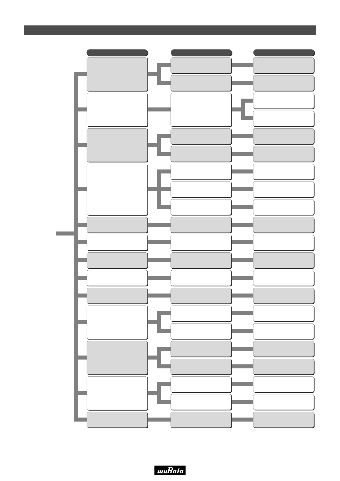
GRM (X5R, X7R, Y5V etc.)
68pF–100µF
GNM
10pF–2.2µF
GRM (C0G)
0.1pF–0.1µF
GRM (U2J etc.)
LLL
2200pF–10µF
LLA/LLM (From 1GHz)
0.01µF–4.7µF
ERB (1MHz to 1GHz)
0.5pF–1000pF
GJM (500MHz to 10GHz)
0.1pF–33pF
GQM (500MHz to 10GHz)
0.1pF–100pF
GMA 100pF–0.47µF
GMD 100pF–1µF
GRM (U2J)
10pF–10000pF
GRM (C0G)
5pF–47pF
GRM (X7R)
220pF–1µF
GR7
10000pF–47000pF
GR4
100pF–10000pF
Type GD 10pF–4700pF
Type GF 10pF–4700pF
Type GC 100pF–330pF
Type GF 470pF–4700pF
Type GB 10000pF–33000pF
GA2
470pF–0.1µF
GCM (X7R etc.)
100pF–47µF
GCM (C0G etc.)
1.0pF–0.1µF
High Capacitance
Array (2 or 4 Elements)
Class1 TC's;
Low Inductance
(Reverse Geometry)
Low Inductance
(Multi Termination)
Low ESR (50V to 500V)
Low ESR, Ultra Small
Lowest ESR
Wire-Die-Bonding
250V/630V/1kV/2kV/3.15kV
Low Dissipation
3.15kV
Low Dissipation
250V/630V/1kV
High Capacitance
350V
High Capacitance
2kV
High Capacitance
Safety Standard
Recognized
Safety Standard
Recognized
AC250V which meet
Japanese Law
High Capacitance
Class1 TC's;
250V/630V
Low Dissipation
Start
Medium V oltage
High Frequency Snubber
Optical Communications
High Frequency
High Speed Decoupling
Frequency Control/Tuning,
Impedance Matching
Decoupling, Smoothing
Automotive
(Power-train,
Safety Equipment)
Medium V oltage
LCD Backlight Inverter
Medium V oltage
Decoupling, Smoothing
Medium V oltage
Only for Camera Flash Circuit
GCM (U2J)
10pF–10000pF
Medium Voltage for Automotive
(Power-train, Safety Equipment)
AC Lines Noise Removal
Medium V oltage
Only for
Information Devices
/ Tip & Ring
Function Type Series
• This PDF catalog is downloaded from the website of Murata Manufacturing co., ltd. Therefore, it’s specifications are subject to change or our products in it may be discontinued without advance notice. Please check with our
!Note
• Please read rating and !CAUTION (for storage, operating, rating, soldering, mounting and handling) in this catalog to prevent smoking and/or burning, etc.
!Note
sales representatives or product engineers before ordering.
• This catalog has only typical specifications because there is no space for detailed specifications. Therefore, please approve our product specifications or transact the approval sheet for product specifications before ordering.
• This PDF catalog has only typical specifications because there is no space for detailed specifications. Therefore, please approve our product specifications or transact the approval sheet for product specifications before ordering.
Selection Guide of Chip Monolithic Ceramic Capacitors
C02E.pdf
09.9.18
7
Page 10
• This PDF catalog is downloaded from the website of Murata Manufacturing co., ltd. Therefore, it’s specifications are subject to change or our products in it may be discontinued without advance notice. Please check with our
!Note
• Please read rating and !CAUTION (for storage, operating, rating, soldering, mounting and handling) in this catalog to prevent smoking and/or burning, etc.
!Note
sales representatives or product engineers before ordering.
• This catalog has only typical specifications because there is no space for detailed specifications. Therefore, please approve our product specifications or transact the approval sheet for product specifications before ordering.
• This PDF catalog has only typical specifications because there is no space for detailed specifications. Therefore, please approve our product specifications or transact the approval sheet for product specifications before ordering.
C02E.pdf
09.9.18
1
Chip Monolithic Ceramic Capacitors
for General Purpose GRM Series
Dimensions (mm)
LW T
0.2 ±0.02
0.2 ±0.02
0.3 ±0.03
0.3 ±0.03
0.25 ±0.05
0.3 ±0.03
0.5 ±0.05
0.5 ±0.05
0.5 +0/-0.1
0.8 ±0.1
0.8 ±0.1
0.6 ±0.1
0.85 ±0.1
1.25 ±0.1
1.0 +0/-0.2
1.25 ±0.1
0.6 ±0.1
0.85 ±0.1
1.6 ±0.15
1.15 ±0.1
1.6 ±0.2
1.6 ±0.2
0.85 +0.15/-0.05
1.0 +0/-0.2
1.15 ±0.1
1.35 ±0.15
2.5 ±0.2
1.6 ±0.2
1.8 ±0.2
2.0 ±0.2
2.5 ±0.2
e
0.07 to 0.14
0.1 to 0.2
0.1 to 0.3
0.15 to 0.35
0.2 to 0.5
0.2 to 0.7
0.3 to 0.8
0.3 min.
g min.
0.13
0.2
0.4
0.3
0.5
0.7
1.5
1.0
e eg
T
L
W
■ Features
1. Higher resistance of solder-leaching due to
the Ni-barriered termination, applicable for
reflow-soldering, and flow-soldering
(GRM18/21/31 type only).
2. The GRM series is lead free product.
3. Smaller size and higher capacitance value.
4. High reliability and no polarity.
5. Excellent pulse responsibility and noise reduction
due to the low impedance at high frequency.
6. The GRM series is available in paper or embossed
tape and reel packaging for automatic placement.
Bulk case packaging is also available for GRM15/
18/21(T=0.6,1.25).
7. Ta replacement.
■ Applications
General electronic equipment
Part Number
GRM022
GRM033
GRM15X
GRM153
GRM155
GRM185
GRM188*
GRM216
GRM219
GRM21A
GRM21B
GRM316
GRM319
GRM31M
GRM31C
GRM329
GRM32A
GRM32M
GRM32N
GRM32C
GRM32R
GRM32D
GRM32E
0.4 ±0.02
0.6 ±0.03
1.0 ±0.05
1.6 ±0.1
2.0 ±0.1
3.2 ±0.15
3.2 ±0.2
3.2 ±0.3
* Bulk Case: 1.6 ±0.07(L)g0.8 ±0.07(W)g0.8 ±0.07(T)
* The figure indicates typical Specification.
8
Page 11
• This PDF catalog is downloaded from the website of Murata Manufacturing co., ltd. Therefore, it’s specifications are subject to change or our products in it may be discontinued without advance notice. Please check with our
!Note
• Please read rating and !CAUTION (for storage, operating, rating, soldering, mounting and handling) in this catalog to prevent smoking and/or burning, etc.
!Note
sales representatives or product engineers before ordering.
• This catalog has only typical specifications because there is no space for detailed specifications. Therefore, please approve our product specifications or transact the approval sheet for product specifications before ordering.
• This PDF catalog has only typical specifications because there is no space for detailed specifications. Therefore, please approve our product specifications or transact the approval sheet for product specifications before ordering.
C02E.pdf
09.9.18
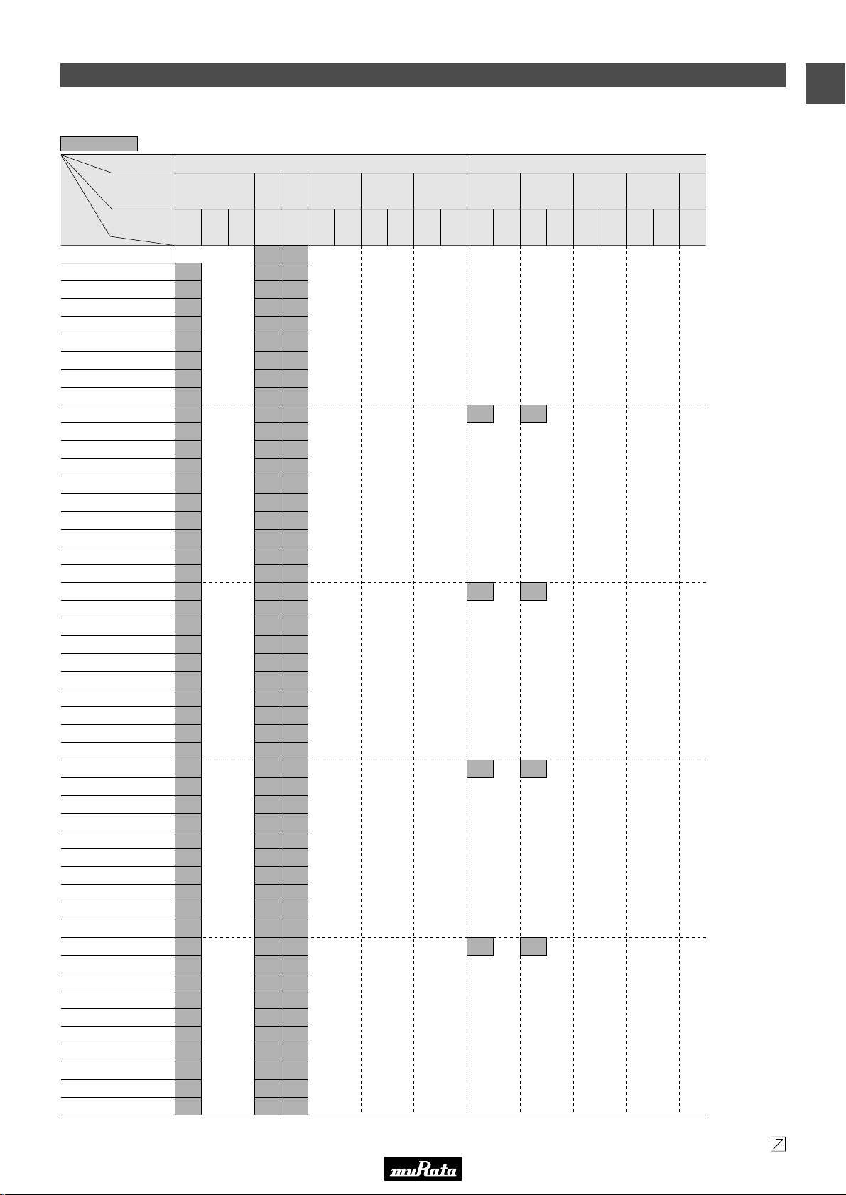
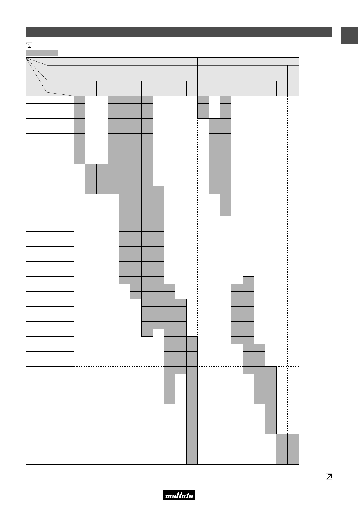
Temperature Compensating Type C0G(5C),U2J(7U) Characteristics
6
Capacitance
The part number code is shown in ( ) and Unit is shown in [ ]. < >: EIA [inch] Code
ex.6: T Dimension [mm]
TC
LxW
[mm]
Rated Voltage
[Vdc]
0.1pF(R10)
0.2pF(R20)
0.3pF(R30)
0.4pF(R40)
0.5pF(R50)
0.6pF(R60)
0.7pF(R70)
0.8pF(R80)
0.9pF(R90)
1.0pF(1R0)
1.1pF(1R1)
1.2pF(1R2)
1.3pF(1R3)
1.4pF(1R4)
1.5pF(1R5)
1.6pF(1R6)
1.7pF(1R7)
1.8pF(1R8)
1.9pF(1R9)
2.0pF(2R0)
2.1pF(2R1)
2.2pF(2R2)
2.3pF(2R3)
2.4pF(2R4)
2.5pF(2R5)
2.6pF(2R6)
2.7pF(2R7)
2.8pF(2R8)
2.9pF(2R9)
3.0pF(3R0)
3.1pF(3R1)
3.2pF(3R2)
3.3pF(3R3)
3.4pF(3R4)
3.5pF(3R5)
3.6pF(3R6)
3.7pF(3R7)
3.8pF(3R8)
3.9pF(3R9)
4.0pF(4R0)
4.1pF(4R1)
4.2pF(4R2)
4.3pF(4R3)
4.4pF(4R4)
4.5pF(4R5)
4.6pF(4R6)
4.7pF(4R7)
4.8pF(4R8)
4.9pF(4R9)
<01005>
16
(1C)
2
2
2
2
2
2
2
2
2
2
2
2
2
2
2
2
2
2
2
2
2
2
2
2
2
2
2
2
2
2
2
2
2
2
2
2
2
2
2
2
2
2
2
2
2
2
2
2
0.4x0.2
(02)
10
(1A)
6.3
(0J)
C0G(5C) U2J(7U)
0.6x0.3
1.0x0.5
(03)
<0201>
50
(1H)
3
3
3
3
3
3
3
3
3
3
3
3
3
3
3
3
3
3
3
3
3
3
3
3
3
3
3
3
3
3
3
3
3
3
3
3
3
3
3
3
3
3
3
3
3
3
3
3
3
(15)
<0402>
50
(1H)
3, 5
3, 5
3, 5
3, 5
3, 5
3, 5
3, 5
3, 5
3, 5
3, 5
3, 5
3, 5
3, 5
3, 5
3, 5
3, 5
3, 5
3, 5
3, 5
3, 5
3, 5
3, 5
3, 5
3, 5
3, 5
3, 5
3, 5
3, 5
3, 5
3, 5
3, 5
3, 5
3, 5
3, 5
3, 5
3, 5
3, 5
3, 5
3, 5
3, 5
3, 5
3, 5
3, 5
3, 5
3, 5
3, 5
3, 5
3, 5
3, 5
1.6x0.8
<0603>
100
(1E)50(1H)
(18)
2.0x1.25
(21)
<0805>
100
(1E)50(1H)
3.2x1.6
(31)
<1206>
100
(1E)50(1H)
0.6x0.3
(03)
<0201>
50
(1H)25(1E)
3
3
3
3
1.0x0.5
(15)
<0402>
50
(1H)10(1A)
5
5
5
5
Capacitance Table
1.6x0.8
<0603>
50
(1H)10(1A)
2.0x1.25
(18)
(21)
<0805>
50
(1H)10(1A)
Continued on the following page.
3.2x1.6
(31)
<1206>
(1H)
1
50
9
Page 12
• This PDF catalog is downloaded from the website of Murata Manufacturing co., ltd. Therefore, it’s specifications are subject to change or our products in it may be discontinued without advance notice. Please check with our
!Note
• Please read rating and !CAUTION (for storage, operating, rating, soldering, mounting and handling) in this catalog to prevent smoking and/or burning, etc.
!Note
sales representatives or product engineers before ordering.
• This catalog has only typical specifications because there is no space for detailed specifications. Therefore, please approve our product specifications or transact the approval sheet for product specifications before ordering.
• This PDF catalog has only typical specifications because there is no space for detailed specifications. Therefore, please approve our product specifications or transact the approval sheet for product specifications before ordering.
C02E.pdf
09.9.18
1
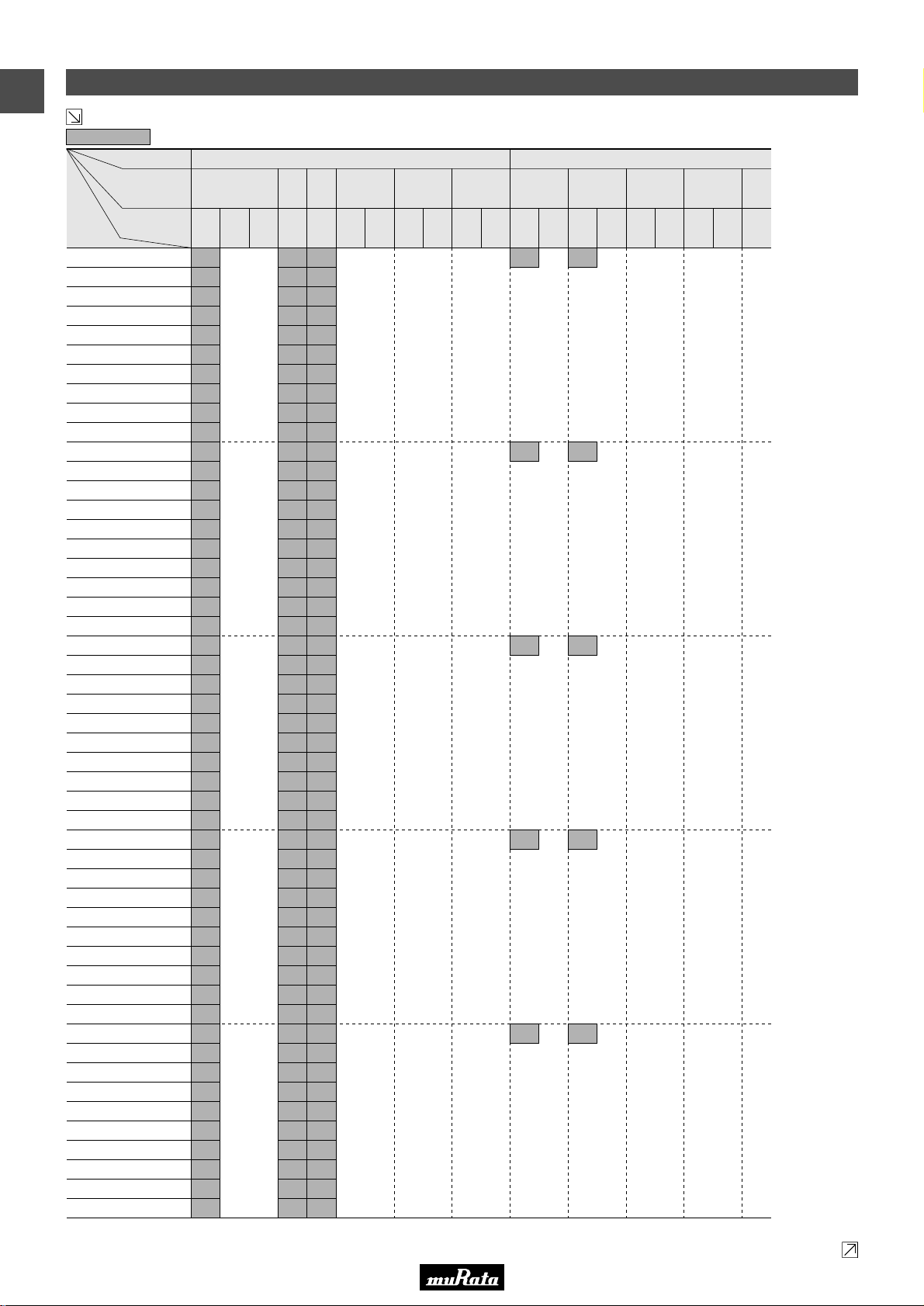
Capacitance Table
Continued from the preceding page.
6
Capacitance
The part number code is shown in ( ) and Unit is shown in [ ]. < >: EIA [inch] Code
ex.6: T Dimension [mm]
TC
LxW
[mm]
Rated Voltage
[Vdc]
5.0pF(5R0)
5.1pF(5R1)
5.2pF(5R2)
5.3pF(5R3)
5.4pF(5R4)
5.5pF(5R5)
5.6pF(5R6)
5.7pF(5R7)
5.8pF(5R8)
5.9pF(5R9)
6.0pF(6R0)
6.1pF(6R1)
6.2pF(6R2)
6.3pF(6R3)
6.4pF(6R4)
6.5pF(6R5)
6.6pF(6R6)
6.7pF(6R7)
6.8pF(6R8)
6.9pF(6R9)
7.0pF(7R0)
7.1pF(7R1)
7.2pF(7R2)
7.3pF(7R3)
7.4pF(7R4)
7.5pF(7R5)
7.6pF(7R6)
7.7pF(7R7)
7.8pF(7R8)
7.9pF(7R9)
8.0pF(8R0)
8.1pF(8R1)
8.2pF(8R2)
8.3pF(8R3)
8.4pF(8R4)
8.5pF(8R5)
8.6pF(8R6)
8.7pF(8R7)
8.8pF(8R8)
8.9pF(8R9)
9.0pF(9R0)
9.1pF(9R1)
9.2pF(9R2)
9.3pF(9R3)
9.4pF(9R4)
9.5pF(9R5)
9.6pF(9R6)
9.7pF(9R7)
9.8pF(9R8)
9.9pF(9R9)
<01005>
16
(1C)
2
2
2
2
2
2
2
2
2
2
2
2
2
2
2
2
2
2
2
2
2
2
2
2
2
2
2
2
2
2
2
2
2
2
2
2
2
2
2
2
2
2
2
2
2
2
2
2
2
2
0.4x0.2
(02)
10
(1A)
6.3
(0J)
C0G(5C) U2J(7U)
0.6x0.3
1.0x0.5
(03)
<0201>
50
(1H)
3
3
3
3
3
3
3
3
3
3
3
3
3
3
3
3
3
3
3
3
3
3
3
3
3
3
3
3
3
3
3
3
3
3
3
3
3
3
3
3
3
3
3
3
3
3
3
3
3
3
(15)
<0402>
50
(1H)
3, 5
3, 5
3, 5
3, 5
3, 5
3, 5
3, 5
3, 5
3, 5
3, 5
3, 5
3, 5
3, 5
3, 5
3, 5
3, 5
3, 5
3, 5
3, 5
3, 5
3, 5
3, 5
3, 5
3, 5
3, 5
3, 5
3, 5
3, 5
3, 5
3, 5
3, 5
3, 5
3, 5
3, 5
3, 5
3, 5
3, 5
3, 5
3, 5
3, 5
3, 5
3, 5
3, 5
3, 5
3, 5
3, 5
3, 5
3, 5
3, 5
3, 5
1.6x0.8
<0603>
100
(1E)50(1H)
(18)
2.0x1.25
(21)
<0805>
100
(1E)50(1H)
3.2x1.6
(31)
<1206>
100
(1E)50(1H)
0.6x0.3
(03)
<0201>
50
(1H)25(1E)
3
3
3
3
3
1.0x0.5
(15)
<0402>
50
(1H)10(1A)
5
5
5
5
5
1.6x0.8
(18)
<0603>
50
(1H)10(1A)
2.0x1.25
<0805>
50
(1H)10(1A)
Continued on the following page.
(21)
3.2x1.6
(31)
<1206>
50
(1H)
10
Page 13
• This PDF catalog is downloaded from the website of Murata Manufacturing co., ltd. Therefore, it’s specifications are subject to change or our products in it may be discontinued without advance notice. Please check with our
!Note
• Please read rating and !CAUTION (for storage, operating, rating, soldering, mounting and handling) in this catalog to prevent smoking and/or burning, etc.
!Note
sales representatives or product engineers before ordering.
• This catalog has only typical specifications because there is no space for detailed specifications. Therefore, please approve our product specifications or transact the approval sheet for product specifications before ordering.
• This PDF catalog has only typical specifications because there is no space for detailed specifications. Therefore, please approve our product specifications or transact the approval sheet for product specifications before ordering.
C02E.pdf
09.9.18
Continued from the preceding page.
6
Capacitance
ex.6: T Dimension [mm]
TC
LxW
[mm]
Rated Voltage
[Vdc]
10pF(100)
12pF(120)
15pF(150)
18pF(180)
22pF(220)
27pF(270)
33pF(330)
39pF(390)
47pF(470)
56pF(560)
68pF(680)
82pF(820)
100pF(101)
120pF(121)
150pF(151)
180pF(181)
220pF(221)
270pF(271)
330pF(331)
390pF(391)
470pF(471)
560pF(561)
680pF(681)
820pF(821)
1000pF(102)
1200pF(122)
1500pF(152)
1800pF(182)
2200pF(222)
2700pF(272)
3300pF(332)
3900pF(392)
<01005>
16
(1C)
2
2
2
2
2
2
2
2
2
0.4x0.2
(02)
10
(1A)
2
2
2
2
6.3
(0J)
2
2
2
2
C0G(5C) U2J(7U)
0.6x0.3
1.0x0.5
(03)
<0201>
50
(1H)
3
3
3
3
3
3
3
3
3
3
3
3
3
(15)
<0402>
50
(1H)
3, 5
3, 5
3, 5
3, 5
3, 5
3, 5
3, 5
3, 5
3, 5
3, 5
3, 5
3, 5
3, 5
3, 5
3, 5
3, 5
3, 5
3, 5
3, 5
3, 5
3, 5
3, 5
3, 5
5
5
1.6x0.8
<0603>
100
(1E)50(1H)
8
8
8
8
8
8
8
8
8
8
8
8
8
8
8
8
8
8
8
8
8
8
8
8
8
8
8
(18)
8
8
8
8
8
8
8
8
8
8
8
8
8
8
8
8
8
8
8
8
8
8
8
8
8
8
8
8
8
8
8
8
2.0x1.25
(21)
<0805>
100
(1E)50(1H)
6
6
6
6
6
6
6
6
6
6
6
6
6
6
6
6
6
6
6
4700pF(472)
5600pF(562)
6800pF(682)
8200pF(822)
10000pF(103)
12000pF(123)
15000pF(153)
18000pF(183)
22000pF(223)
27000pF(273)
33000pF(333)
39000pF(393)
47000pF(473)
56000pF(563)
68000pF(683)
82000pF(823)
0.1µF(104)
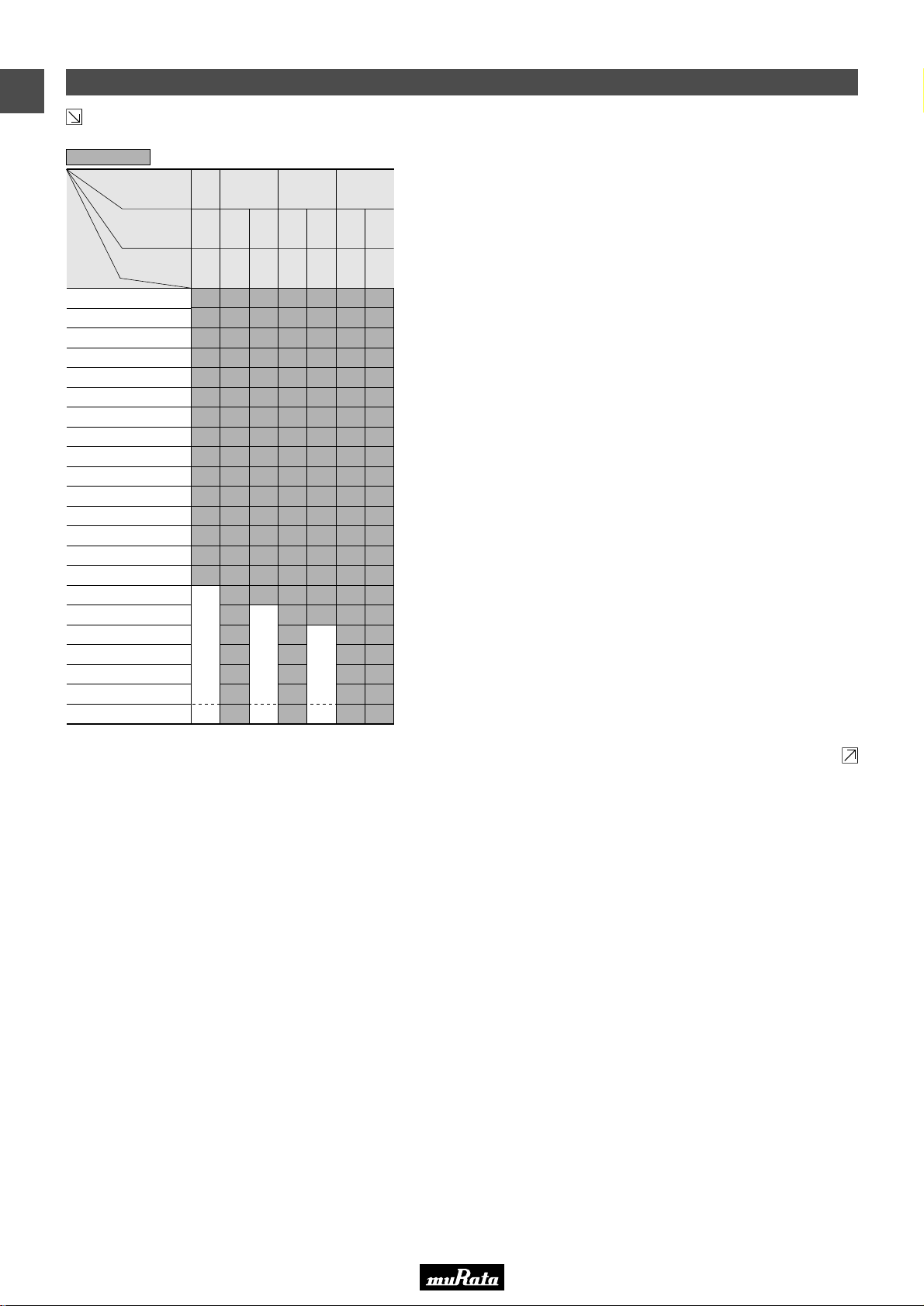
The part number code is shown in ( ) and Unit is shown in [ ]. < >: EIA [inch] Code
6
6
6
6
6
6
6
6
9
9
9
9
9
9
B
B
3.2x1.6
(31)
<1206>
100
(1E)50(1H)
9
9
9
9
9
9
9
9
9
9
9
9
9
9
9
9
9
9
9
9
9
9
M
M
C
C
C
0.6x0.3
(03)
<0201>
50
(1H)25(1E)
3
3
3
3
3
3
3
3
3
3
3
3
3
1.0x0.5
(15)
<0402>
50
(1H)10(1A)
5
5
5
5
5
5
5
5
5
5
5
5
5
5
5
5
5
5
5
5
5
5
5
5
Capacitance Table
1.6x0.8
<0603>
50
(1H)10(1A)
8
8
8
8
5, 8
5, 8
5, 8
5, 8
5, 8
8
8
8
8
2.0x1.25
(18)
(21)
<0805>
50
(1H)10(1A)
5
5
5
5
6
8
6
8
6
8
6
8
9
9
A
B
B
9
B
B
B
Continued on the following page.
3.2x1.6
(31)
<1206>
(1H)
1
50
9
M
M
M
11
Page 14
• This PDF catalog is downloaded from the website of Murata Manufacturing co., ltd. Therefore, it’s specifications are subject to change or our products in it may be discontinued without advance notice. Please check with our
!Note
• Please read rating and !CAUTION (for storage, operating, rating, soldering, mounting and handling) in this catalog to prevent smoking and/or burning, etc.
!Note
sales representatives or product engineers before ordering.
• This catalog has only typical specifications because there is no space for detailed specifications. Therefore, please approve our product specifications or transact the approval sheet for product specifications before ordering.
• This PDF catalog has only typical specifications because there is no space for detailed specifications. Therefore, please approve our product specifications or transact the approval sheet for product specifications before ordering.
C02E.pdf
09.9.18
1
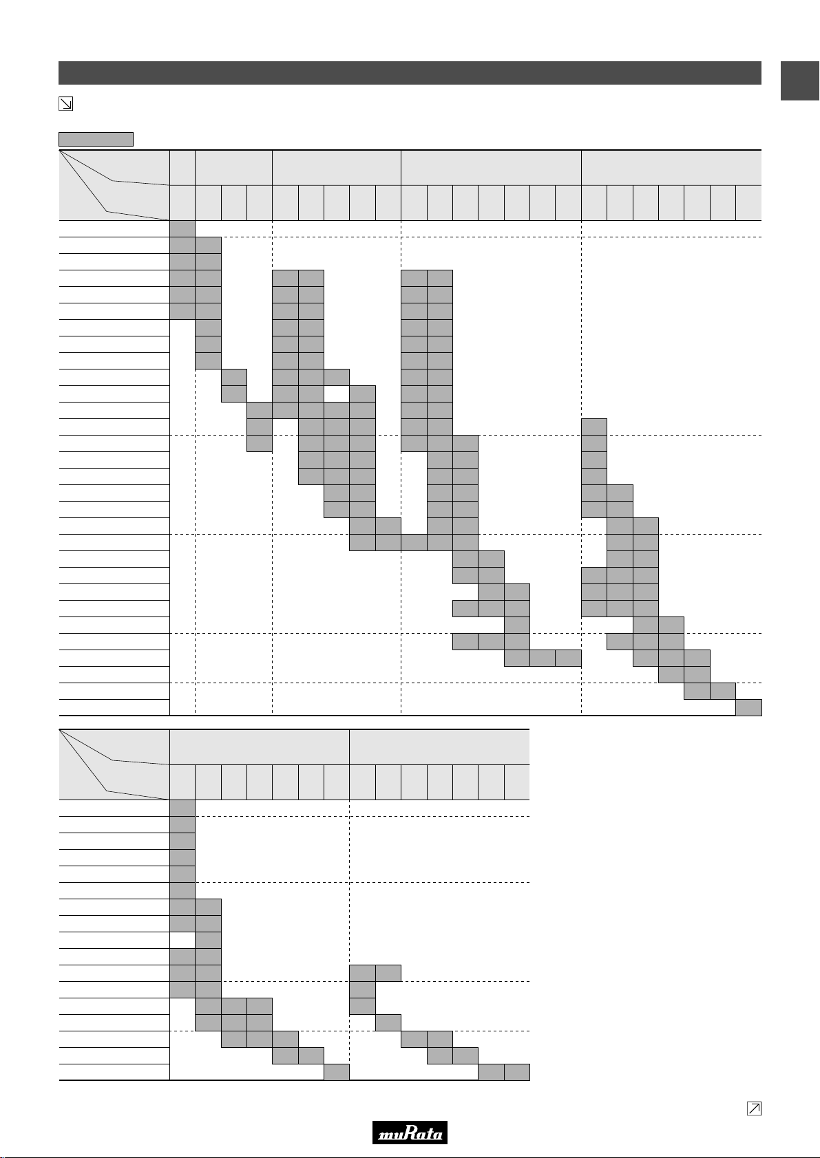
Capacitance Table
Continued from the preceding page.
Temperature Compensating Type P2H(6P),R2H(6R),S2H(6S),T2H(6T) Characteristics
6
Capacitance
The part number code is shown in ( ) and Unit is shown in [ ]. < >: EIA [inch] Code
ex.6: T Dimension [mm]
TC
LxW
[mm]
Rated Voltage
[Vdc]
1.0pF(1R0)
2.0pF(2R0)
3.0pF(3R0)
4.0pF(4R0)
5.0pF(5R0)
6.0pF(6R0)
7.0pF(7R0)
8.0pF(8R0)
9.0pF(9R0)
10pF(100)
12pF(120)
15pF(150)
18pF(180)
22pF(220)
27pF(270)
33pF(330)
39pF(390)
47pF(470)
56pF(560)
68pF(680)
82pF(820)
100pF(101)
P2H
(6P)
1.0x0.5
(15)
<0402>
50
(1H)
5
5
5
5
5
5
5
5
5
5
5
5
5
5
5
R2H
(6R)
0.6x0.3
(03)
<0201>
25
(1E)
3
3
3
3
3
3
3
3
3
3
3
3
3
3
3
3
3
3
3
3
3
3
S2H
(6S)
1.0x0.5
0.6x0.3
(15)
<0402>
50
(1H)
5
5
5
5
5
5
5
5
5
5
5
5
5
5
5
5
1.0x0.5
(03)
(15)
<0201>
<0402>
25
(1E)50(1H)25(1E)50(1H)
3
3
3
3
3
3
3
3
3
3
3
3
3
3
3
3
3
3
3
3
3
3
T2H
(6T)
0.6x0.3
1.0x0.5
(03)
(15)
<0201>
<0402>
5
3
5
5
3
5
5
3
5
5
3
5
5
3
5
5
3
5
5
3
5
5
3
5
5
3
5
5
3
5
5
3
5
5
3
5
5
3
5
5
3
5
5
3
5
5
3
5
5
3
5
5
3
5
3
5
3
5
3
5
3
Continued on the following page.
12
Page 15
• This PDF catalog is downloaded from the website of Murata Manufacturing co., ltd. Therefore, it’s specifications are subject to change or our products in it may be discontinued without advance notice. Please check with our
!Note
• Please read rating and !CAUTION (for storage, operating, rating, soldering, mounting and handling) in this catalog to prevent smoking and/or burning, etc.
!Note
sales representatives or product engineers before ordering.
• This catalog has only typical specifications because there is no space for detailed specifications. Therefore, please approve our product specifications or transact the approval sheet for product specifications before ordering.
• This PDF catalog has only typical specifications because there is no space for detailed specifications. Therefore, please approve our product specifications or transact the approval sheet for product specifications before ordering.
C02E.pdf
09.9.18
Continued from the preceding page.
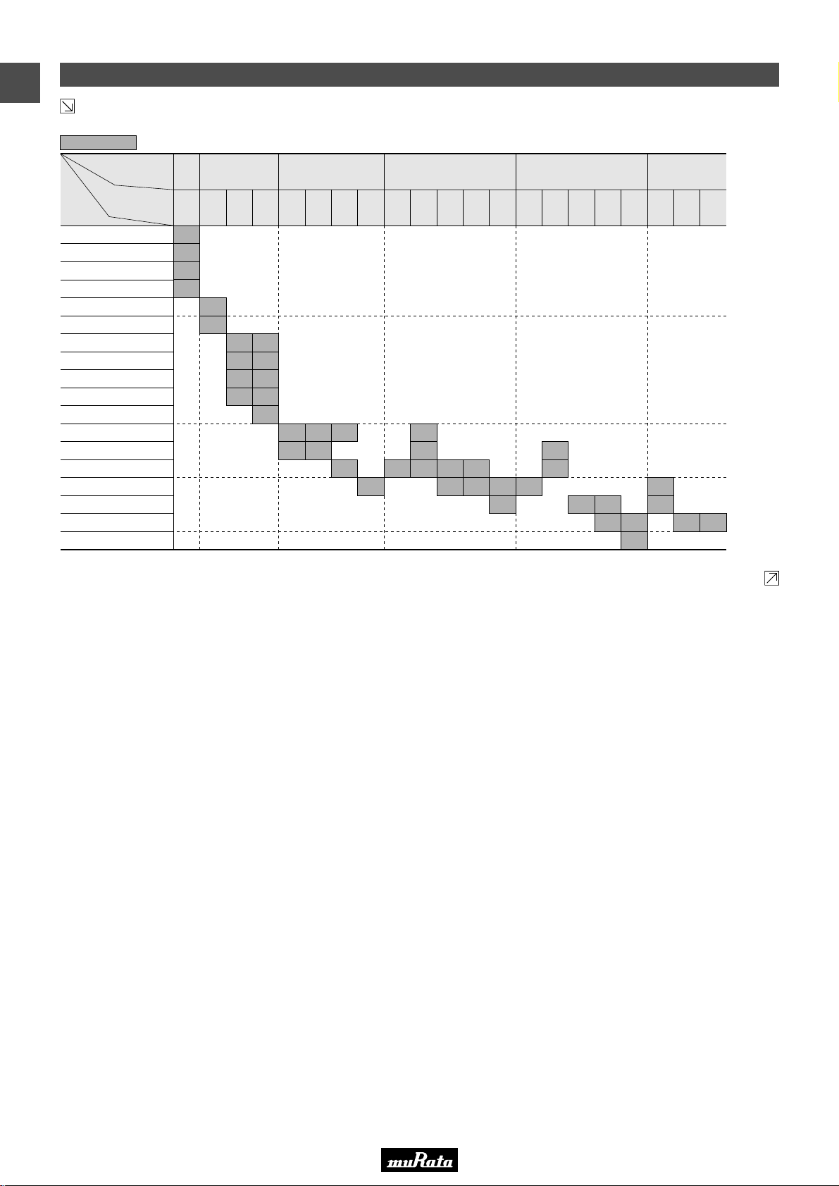
High Dielectric Constant Type X7R(R7)/X7S(C7)/X7T(D7)/X7U(E7) Characteristics
5
Capacitance
10000pF(103)
15000pF(153)
22000pF(223)
33000pF(333)
47000pF(473)
68000pF(683)
ex.5: T Dimension [mm]
LxW
[mm]
Rated Voltage
[Vdc]
68pF(680)
100pF(101)
150pF(151)
220pF(221)
330pF(331)
470pF(471)
680pF(681)
1000pF(102)
1500pF(152)
2200pF(222)
3300pF(332)
4700pF(472)
6800pF(682)
0.10µF(104)
0.15µF(154)
0.22µF(224)
0.33µF(334)
0.47µF(474)
0.68µF(684)
1.0µF(105)
2.2µF(225)
4.7µF(475)
10µF(106)
22µF(226)
0.4x0.2
(02)
<01005>
10
25
(1A)
(1E)16(1C)10(1A)
2
2
2
2
2
2
0.6x0.3
<0201>
3
3
3
3
3
3
3
3
(03)
3
3
1.0x0.5
(15)
<0402>
100
(2A)50(1H)25(1E)16(1C)10(1A)
5
X, 5
5
X, 5
5
X, 5
5
X, 5
5
X, 5
5
X, 5
5
5
X
5
5
3
5
5
5
3
3
5
5
5
5
5
5
5
5
5
5
X
X
X
X
5
5
5
5
555
1.6x0.8
<0603>
100
(2A)50(1H)25(1E)16(1C)10(1A)
8
8
8
8
8
8
8
8
8
8
8
8
8
8
8
8
8
8
8
8
8
8
8
8
8
8
8
8
8
8
8
8
8
5
8
8
8
8
8
8
8
(18)
8
8
8
8
8
6.3
(0J)4(0G)
8
8
8
5, 8
8 8 8
Capacitance Table
2.0x1.25
(21)
<0805>
100
(2A)50(1H)25(1E)16(1C)10(1A)
9
B
B
B
B
9
B
B
B
9
B
B
B
B
A
B
B
A
9
B
B
B
9
9
9
B
9, B
B
B
BBB
(0J)4(0G)
B
B B
1
6.3
B
M
M
9
M
M
M
CCM
3.2x1.6
<1206>
C
C
(31)
M
C
C C
6.3
(0J)4(0G)
C C
100
(2A)50(1H)35(YA)25(1E)16(1C)10(1A)
C
C
E
C
LxW
[mm]
Rated Voltage
Capacitance
15000pF(153)
22000pF(223)
33000pF(333)
47000pF(473)
68000pF(683)
0.10µF(104)
0.15µF(154)
0.22µF(224)
100
[Vdc]
(2A)50(1H)25(1E)16(1C)10(1A)
9
M
M
M
M
9
M
M
0.33µF(334)
0.47µF(474)
0.68µF(684)
1.0µF(105)
M
M
C
2.2µF(225)
4.7µF(475)
10µF(106)
22µF(226)
47µF(476)
The part number code is shown in ( ) and Unit is shown in [ ]. < >: EIA [inch] Code
3.2x2.5
(32)
<1210>
6.3
(0J)
N
E
E
D
E E
E E
Continued on the following page.
13
Page 16
• This PDF catalog is downloaded from the website of Murata Manufacturing co., ltd. Therefore, it’s specifications are subject to change or our products in it may be discontinued without advance notice. Please check with our
!Note
• Please read rating and !CAUTION (for storage, operating, rating, soldering, mounting and handling) in this catalog to prevent smoking and/or burning, etc.
!Note
sales representatives or product engineers before ordering.
• This catalog has only typical specifications because there is no space for detailed specifications. Therefore, please approve our product specifications or transact the approval sheet for product specifications before ordering.
• This PDF catalog has only typical specifications because there is no space for detailed specifications. Therefore, please approve our product specifications or transact the approval sheet for product specifications before ordering.
C02E.pdf
09.9.18
1
Capacitance Table
Continued from the preceding page.
High Dielectric Constant Type X6S(C8)/X6T(D8) Characteristics
5
Capacitance
15000pF(153)
22000pF(223)
33000pF(333)
47000pF(473)
68000pF(683)
The part number code is shown in ( ) and Unit is shown in [ ]. < >: EIA [inch] Code
ex.5: T Dimension [mm]
LxW
[mm]
Rated Voltage
[Vdc]
0.10µF(104)
0.15µF(154)
0.22µF(224)
0.33µF(334)
0.47µF(474)
0.68µF(684)
1.0µF(105)
2.2µF(225)
4.7µF(475)
10µF(106)
22µF(226)
47µF(476)
100µF(107)
0.6x0.3
(03)
<0201>
6.3
(0J)
3
3
3
3
1.0x0.5
(15)
<0402>
25
6.3
(1E)
(0J)4(0G)10(1A)
5
5
1.6x0.8
(18)
<0603>
6.3
(0J)4(0G)
5
5
5
5
5
5
5
5
5
58588
2.5
(0E)
8 B
8
2.0x1.25
(21)
<0805>
25
(1E)16(1C)10(1A)
6
9
B 9B9
3.2x1.6
(31)
<1206>
6.3
(0J)4(0G)25(1E)16(1C)10(1A)
6
9
9, B 9BC
C C
3.2x2.5
(32)
<1210>
6.3
(0J)4(0G)
C C
25
(1E)10(1A)
D
E
E E
C
Continued on the following page.
6.3
(0J)
14
Page 17
• This PDF catalog is downloaded from the website of Murata Manufacturing co., ltd. Therefore, it’s specifications are subject to change or our products in it may be discontinued without advance notice. Please check with our
!Note
• Please read rating and !CAUTION (for storage, operating, rating, soldering, mounting and handling) in this catalog to prevent smoking and/or burning, etc.
!Note
sales representatives or product engineers before ordering.
• This catalog has only typical specifications because there is no space for detailed specifications. Therefore, please approve our product specifications or transact the approval sheet for product specifications before ordering.
• This PDF catalog has only typical specifications because there is no space for detailed specifications. Therefore, please approve our product specifications or transact the approval sheet for product specifications before ordering.
C02E.pdf
09.9.18
Continued from the preceding page.
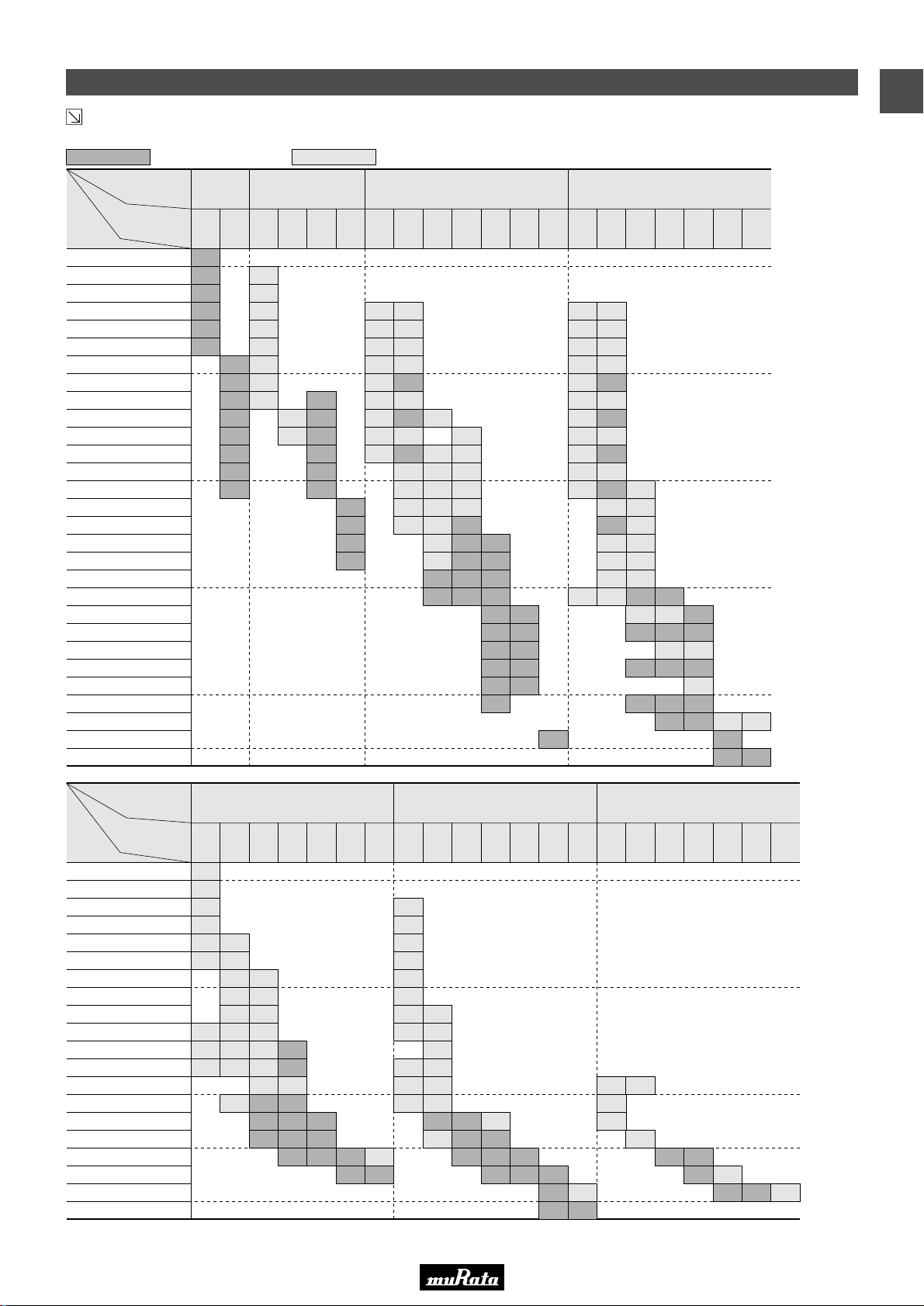
High Dielectric Constant Type X5R(R6) Characteristics
5
Capacitance
10000pF(103)
15000pF(153)
22000pF(223)
33000pF(333)
47000pF(473)
68000pF(683)
ex.5: T Dimension [mm] : Please refer to X7R(R7) etc Characteristics.
LxW
[mm]
Rated Voltage
[Vdc]
68pF(680)
100pF(101)
150pF(151)
220pF(221)
330pF(331)
470pF(471)
680pF(681)
1000pF(102)
1500pF(152)
2200pF(222)
3300pF(332)
4700pF(472)
6800pF(682)
0.10µF(104)
0.4x0.2
(02)
<01005>
10
6.3
(1A)
(0J)25(1E)16(1C)10(1A)
2
2
2
2
2
2
2
2
2
2
2
2
2
2
0.6x0.3
(03)
<0201>
6.3
100
(0J)
(2A)50(1H)25(1E)16(1C)10(1A)
5
3
3
3
3
3
3
3
3
3
3
5
5
5
5
0.15µF(154)
0.22µF(224)
0.33µF(334)
0.47µF(474)
0.68µF(684)
1.0µF(105)
2.2µF(225)
4.7µF(475)
10µF(106)
1.0x0.5
(15)
<0402>
5
5
5
5
5
(0J)4(0G)
5
5
5
5
5
5
5
5
5
5
6.3
Capacitance Table
1
1.6x0.8
(18)
<0603>
100
(2A)50(1H)25(1E)16(1C)10(1A)
8
8
8
8
8
8
8
5
5
5
5
5
5
8
8
8
8
8
5, 8
8
6.3
(0J)4(0G)
8
8
8
5
8
8
8 8
2.0x1.25
(21)
<0805>
6.3
(0J)4(0G)
100
(2A)50(1H)25(1E)16(1C)10(1A)
Capacitance
LxW
[mm]
Rated Voltage
[Vdc]
100
(2A)50(1H)25(1E)16(1C)10(1A)
6800pF(682)
10000pF(103)
15000pF(153)
22000pF(223)
33000pF(333)
47000pF(473)
68000pF(683)
0.10µF(104)
0.15µF(154)
0.22µF(224)
0.33µF(334)
0.47µF(474)
B
B
0.68µF(684)
B
1.0µF(105)
2.2µF(225)
4.7µF(475)
10µF(106)
22µF(226)
6
9, B
B
9, B
9, B
B
B
9
9, B 9
B 9
47µF(476)
100µF(107)
The part number code is shown in ( ) and Unit is shown in [ ]. < >: EIA [inch] Code
C 6
3.2x1.6
(31)
<1206>
9,CC9,C
9, CC9
6.3
(0J)4(0G)
C C
C
C C
3.2x2.5
(32)
<1210>
100
(2A)50(1H)35(YA)25(1E)16(1C)10(1A)
E D
E
E E
6.3
(0J)
15
Page 18
• This PDF catalog is downloaded from the website of Murata Manufacturing co., ltd. Therefore, it’s specifications are subject to change or our products in it may be discontinued without advance notice. Please check with our
!Note
• Please read rating and !CAUTION (for storage, operating, rating, soldering, mounting and handling) in this catalog to prevent smoking and/or burning, etc.
!Note
sales representatives or product engineers before ordering.
• This catalog has only typical specifications because there is no space for detailed specifications. Therefore, please approve our product specifications or transact the approval sheet for product specifications before ordering.
• This PDF catalog has only typical specifications because there is no space for detailed specifications. Therefore, please approve our product specifications or transact the approval sheet for product specifications before ordering.
C02E.pdf
09.9.18
1
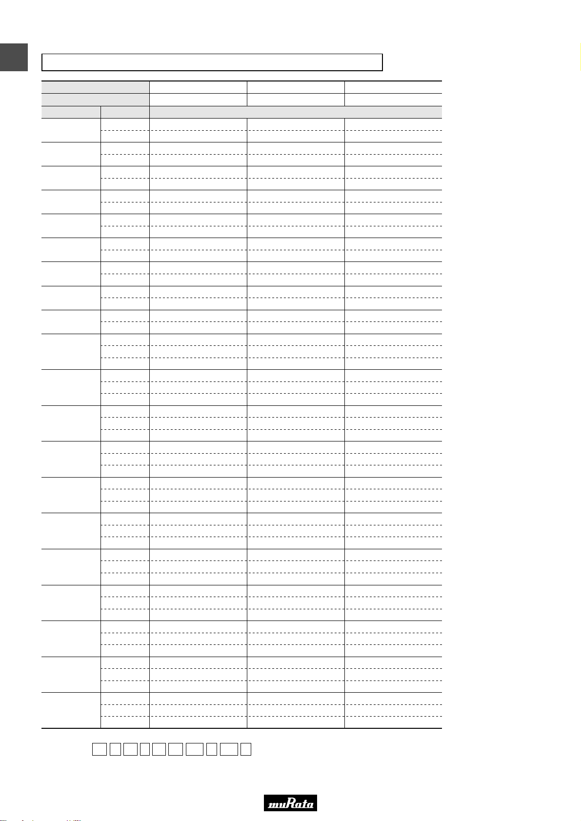
Temperature Compensating Type C0G(5C) Characteristics
LxW [mm]
Rated Volt. [Vdc]
Capacitance Tolerance Part Number
0.1pF(R10)
0.2pF(R20)
0.3pF(R30)
0.4pF(R40)
0.5pF(R50)
0.6pF(R60)
0.7pF(R70)
0.8pF(R80)
0.9pF(R90)
1.0pF(1R0)
1.1pF(1R1)
1.2pF(1R2)
1.3pF(1R3)
1.4pF(1R4)
1.5pF(1R5)
1.6pF(1R6)
1.7pF(1R7)
1.8pF(1R8)
1.9pF(1R9)
2.0pF(2R0)
The part number code is shown in ( ) and Unit is shown in [ ]. < >: EIA [inch] Code
(Part Number)
Packaging Code in Part Number is a code shows STD 180mm Reel Taping.
±0.05pF(W)
±0.1pF(B)
±0.05pF(W)
±0.1pF(B)
±0.05pF(W)
±0.1pF(B)
±0.05pF(W)
±0.1pF(B)
±0.05pF(W)
±0.1pF(B)
±0.05pF(W)
±0.1pF(B)
±0.05pF(W)
±0.1pF(B)
±0.05pF(W)
±0.1pF(B)
±0.05pF(W)
±0.1pF(B)
±0.05pF(W)
±0.1pF(B)
±0.25pF(C)
±0.05pF(W)
±0.1pF(B)
±0.25pF(C)
±0.05pF(W)
±0.1pF(B)
±0.25pF(C)
±0.05pF(W)
±0.1pF(B)
±0.25pF(C)
±0.05pF(W)
±0.1pF(B)
±0.25pF(C)
±0.05pF(W)
±0.1pF(B)
±0.25pF(C)
±0.05pF(W)
±0.1pF(B)
±0.25pF(C)
±0.05pF(W)
±0.1pF(B)
±0.25pF(C)
±0.05pF(W)
±0.1pF(B)
±0.25pF(C)
±0.05pF(W)
±0.1pF(B)
±0.25pF(C)
±0.05pF(W)
±0.1pF(B)
±0.25pF(C)
GR M 02 2 5C 1C R20 W D05 L
e r t y u i o !0
wq
0.4x0.2(02)<01005> 0.6x0.3(03)<0201> 1.0x0.5(15)<0402>
16(1C)
GRM0225C1CR20WD05L
GRM0225C1CR20BD05L
GRM0225C1CR30WD05L
GRM0225C1CR30BD05L
GRM0225C1CR40WD05L
GRM0225C1CR40BD05L
GRM0225C1CR50WD05L
GRM0225C1CR50BD05L
GRM0225C1CR60WD05L
GRM0225C1CR60BD05L
GRM0225C1CR70WD05L
GRM0225C1CR70BD05L
GRM0225C1CR80WD05L
GRM0225C1CR80BD05L
GRM0225C1CR90WD05L
GRM0225C1CR90BD05L
GRM0225C1C1R0WD05L
GRM0225C1C1R0BD05L
GRM0225C1C1R0CD05L
GRM0225C1C1R1WD05L
GRM0225C1C1R1BD05L
GRM0225C1C1R1CD05L
GRM0225C1C1R2WD05L
GRM0225C1C1R2BD05L
GRM0225C1C1R2CD05L
GRM0225C1C1R3WD05L
GRM0225C1C1R3BD05L
GRM0225C1C1R3CD05L
GRM0225C1C1R4WD05L
GRM0225C1C1R4BD05L
GRM0225C1C1R4CD05L
GRM0225C1C1R5WD05L
GRM0225C1C1R5BD05L
GRM0225C1C1R5CD05L
GRM0225C1C1R6WD05L
GRM0225C1C1R6BD05L
GRM0225C1C1R6CD05L
GRM0225C1C1R7WD05L
GRM0225C1C1R7BD05L
GRM0225C1C1R7CD05L
GRM0225C1C1R8WD05L
GRM0225C1C1R8BD05L
GRM0225C1C1R8CD05L
GRM0225C1C1R9WD05L
GRM0225C1C1R9BD05L
GRM0225C1C1R9CD05L
GRM0225C1C2R0WD05L
GRM0225C1C2R0BD05L
GRM0225C1C2R0CD05L
GRM0335C1HR10WD01D
GRM0335C1HR10BD01D
GRM0335C1HR20WD01D
GRM0335C1HR20BD01D
GRM0335C1HR30WD01D
GRM0335C1HR30BD01D
GRM0335C1HR40WD01D
GRM0335C1HR40BD01D
GRM0335C1HR50WD01D
GRM0335C1HR50BD01D
GRM0335C1HR60WD01D
GRM0335C1HR60BD01D
GRM0335C1HR70WD01D
GRM0335C1HR70BD01D
GRM0335C1HR80WD01D
GRM0335C1HR80BD01D
GRM0335C1HR90WD01D
GRM0335C1HR90BD01D
GRM0335C1H1R0WD01D
GRM0335C1H1R0BD01D
GRM0335C1H1R0CD01D
GRM0335C1H1R1WD01D
GRM0335C1H1R1BD01D
GRM0335C1H1R1CD01D
GRM0335C1H1R2WD01D
GRM0335C1H1R2BD01D
GRM0335C1H1R2CD01D
GRM0335C1H1R3WD01D
GRM0335C1H1R3BD01D
GRM0335C1H1R3CD01D
GRM0335C1H1R4WD01D
GRM0335C1H1R4BD01D
GRM0335C1H1R4CD01D
GRM0335C1H1R5WD01D
GRM0335C1H1R5BD01D
GRM0335C1H1R5CD01D
GRM0335C1H1R6WD01D
GRM0335C1H1R6BD01D
GRM0335C1H1R6CD01D
GRM0335C1H1R7WD01D
GRM0335C1H1R7BD01D
GRM0335C1H1R7CD01D
GRM0335C1H1R8WD01D
GRM0335C1H1R8BD01D
GRM0335C1H1R8CD01D
GRM0335C1H1R9WD01D
GRM0335C1H1R9BD01D
GRM0335C1H1R9CD01D
GRM0335C1H2R0WD01D
GRM0335C1H2R0BD01D
GRM0335C1H2R0CD01D
50(1H)
qProduct ID wSeries eDimension (LxW) rDimension (T)
tTemperature Characteristics yRated Voltage uCapacitance
iCapacitance Tolerance oIndividual Specification Code !0Packaging*
50(1H)
GRM1555C1HR10WA01D
GRM1555C1HR10BA01D
GRM1555C1HR20WA01D
GRM1555C1HR20BA01D
GRM1555C1HR30WA01D
GRM1555C1HR30BA01D
GRM1555C1HR40WA01D
GRM1555C1HR40BA01D
GRM1555C1HR50WA01D
GRM1555C1HR50BA01D
GRM1555C1HR60WA01D
GRM1555C1HR60BA01D
GRM1555C1HR70WA01D
GRM1555C1HR70BA01D
GRM1555C1HR80WA01D
GRM1555C1HR80BA01D
GRM1555C1HR90WA01D
GRM1555C1HR90BA01D
GRM1555C1H1R0WA01D
GRM1555C1H1R0BA01D
GRM1555C1H1R0CA01D
GRM1555C1H1R1WA01D
GRM1555C1H1R1BA01D
GRM1555C1H1R1CA01D
GRM1555C1H1R2WA01D
GRM1555C1H1R2BA01D
GRM1555C1H1R2CA01D
GRM1555C1H1R3WA01D
GRM1555C1H1R3BA01D
GRM1555C1H1R3CA01D
GRM1555C1H1R4WA01D
GRM1555C1H1R4BA01D
GRM1555C1H1R4CA01D
GRM1555C1H1R5WA01D
GRM1555C1H1R5BA01D
GRM1555C1H1R5CA01D
GRM1555C1H1R6WA01D
GRM1555C1H1R6BA01D
GRM1555C1H1R6CA01D
GRM1555C1H1R7WA01D
GRM1555C1H1R7BA01D
GRM1555C1H1R7CA01D
GRM1555C1H1R8WA01D
GRM1555C1H1R8BA01D
GRM1555C1H1R8CA01D
GRM1555C1H1R9WA01D
GRM1555C1H1R9BA01D
GRM1555C1H1R9CA01D
GRM1555C1H2R0WA01D
GRM1555C1H2R0BA01D
GRM1555C1H2R0CA01D
*GRM022: D is applicable.
16
Page 19
• This PDF catalog is downloaded from the website of Murata Manufacturing co., ltd. Therefore, it’s specifications are subject to change or our products in it may be discontinued without advance notice. Please check with our
!Note
• Please read rating and !CAUTION (for storage, operating, rating, soldering, mounting and handling) in this catalog to prevent smoking and/or burning, etc.
!Note
sales representatives or product engineers before ordering.
• This catalog has only typical specifications because there is no space for detailed specifications. Therefore, please approve our product specifications or transact the approval sheet for product specifications before ordering.
• This PDF catalog has only typical specifications because there is no space for detailed specifications. Therefore, please approve our product specifications or transact the approval sheet for product specifications before ordering.
C02E.pdf
09.9.18
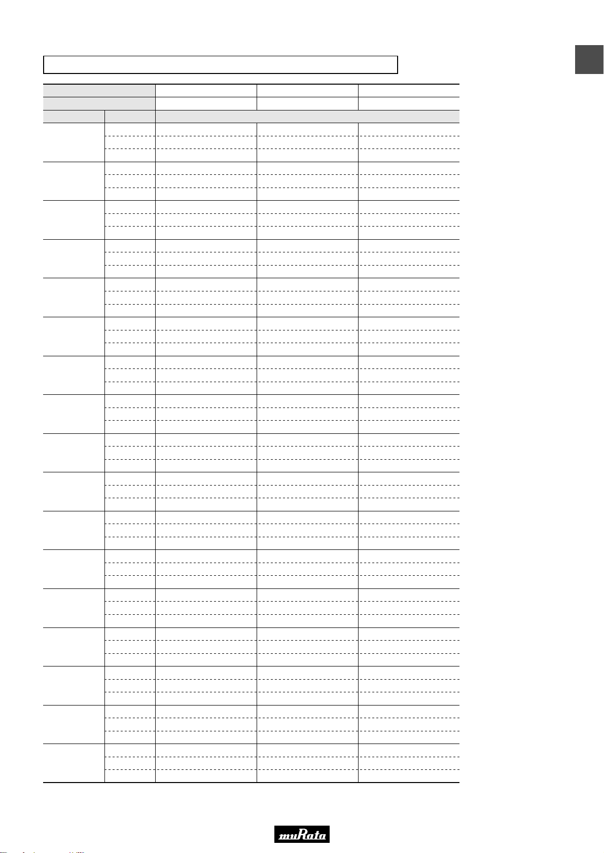
Temperature Compensating Type C0G(5C) Characteristics
LxW [mm]
Rated Volt. [Vdc]
Capacitance Tolerance Part Number
2.1pF(2R1)
2.2pF(2R2)
2.3pF(2R3)
2.4pF(2R4)
2.5pF(2R5)
2.6pF(2R6)
2.7pF(2R7)
2.8pF(2R8)
2.9pF(2R9)
3.0pF(3R0)
3.1pF(3R1)
3.2pF(3R2)
3.3pF(3R3)
3.4pF(3R4)
3.5pF(3R5)
3.6pF(3R6)
3.7pF(3R7)
The part number code is shown in ( ) and Unit is shown in [ ]. < >: EIA [inch] Code
±0.05pF(W)
±0.1pF(B)
±0.25pF(C)
±0.05pF(W)
±0.1pF(B)
±0.25pF(C)
±0.05pF(W)
±0.1pF(B)
±0.25pF(C)
±0.05pF(W)
±0.1pF(B)
±0.25pF(C)
±0.05pF(W)
±0.1pF(B)
±0.25pF(C)
±0.05pF(W)
±0.1pF(B)
±0.25pF(C)
±0.05pF(W)
±0.1pF(B)
±0.25pF(C)
±0.05pF(W)
±0.1pF(B)
±0.25pF(C)
±0.05pF(W)
±0.1pF(B)
±0.25pF(C)
±0.05pF(W)
±0.1pF(B)
±0.25pF(C)
±0.05pF(W)
±0.1pF(B)
±0.25pF(C)
±0.05pF(W)
±0.1pF(B)
±0.25pF(C)
±0.05pF(W)
±0.1pF(B)
±0.25pF(C)
±0.05pF(W)
±0.1pF(B)
±0.25pF(C)
±0.05pF(W)
±0.1pF(B)
±0.25pF(C)
±0.05pF(W)
±0.1pF(B)
±0.25pF(C)
±0.05pF(W)
±0.1pF(B)
±0.25pF(C)
0.4x0.2(02)<01005>
16(1C)
GRM0225C1C2R1WD05L
GRM0225C1C2R1BD05L
GRM0225C1C2R1CD05L
GRM0225C1C2R2WD05L
GRM0225C1C2R2BD05L
GRM0225C1C2R2CD05L
GRM0225C1C2R3WD05L
GRM0225C1C2R3BD05L
GRM0225C1C2R3CD05L
GRM0225C1C2R4WD05L
GRM0225C1C2R4BD05L
GRM0225C1C2R4CD05L
GRM0225C1C2R5WD05L
GRM0225C1C2R5BD05L
GRM0225C1C2R5CD05L
GRM0225C1C2R6WD05L
GRM0225C1C2R6BD05L
GRM0225C1C2R6CD05L
GRM0225C1C2R7WD05L
GRM0225C1C2R7BD05L
GRM0225C1C2R7CD05L
GRM0225C1C2R8WD05L
GRM0225C1C2R8BD05L
GRM0225C1C2R8CD05L
GRM0225C1C2R9WD05L
GRM0225C1C2R9BD05L
GRM0225C1C2R9CD05L
GRM0225C1C3R0WD05L
GRM0225C1C3R0BD05L
GRM0225C1C3R0CD05L
GRM0225C1C3R1WD05L
GRM0225C1C3R1BD05L
GRM0225C1C3R1CD05L
GRM0225C1C3R2WD05L
GRM0225C1C3R2BD05L
GRM0225C1C3R2CD05L
GRM0225C1C3R3WD05L
GRM0225C1C3R3BD05L
GRM0225C1C3R3CD05L
GRM0225C1C3R4WD05L
GRM0225C1C3R4BD05L
GRM0225C1C3R4CD05L
GRM0225C1C3R5WD05L
GRM0225C1C3R5BD05L
GRM0225C1C3R5CD05L
GRM0225C1C3R6WD05L
GRM0225C1C3R6BD05L
GRM0225C1C3R6CD05L
GRM0225C1C3R7WD05L
GRM0225C1C3R7BD05L
GRM0225C1C3R7CD05L
0.6x0.3(03)<0201>
50(1H)
GRM0335C1H2R1WD01D
GRM0335C1H2R1BD01D
GRM0335C1H2R1CD01D
GRM0335C1H2R2WD01D
GRM0335C1H2R2BD01D
GRM0335C1H2R2CD01D
GRM0335C1H2R3WD01D
GRM0335C1H2R3BD01D
GRM0335C1H2R3CD01D
GRM0335C1H2R4WD01D
GRM0335C1H2R4BD01D
GRM0335C1H2R4CD01D
GRM0335C1H2R5WD01D
GRM0335C1H2R5BD01D
GRM0335C1H2R5CD01D
GRM0335C1H2R6WD01D
GRM0335C1H2R6BD01D
GRM0335C1H2R6CD01D
GRM0335C1H2R7WD01D
GRM0335C1H2R7BD01D
GRM0335C1H2R7CD01D
GRM0335C1H2R8WD01D
GRM0335C1H2R8BD01D
GRM0335C1H2R8CD01D
GRM0335C1H2R9WD01D
GRM0335C1H2R9BD01D
GRM0335C1H2R9CD01D
GRM0335C1H3R0WD01D
GRM0335C1H3R0BD01D
GRM0335C1H3R0CD01D
GRM0335C1H3R1WD01D
GRM0335C1H3R1BD01D
GRM0335C1H3R1CD01D
GRM0335C1H3R2WD01D
GRM0335C1H3R2BD01D
GRM0335C1H3R2CD01D
GRM0335C1H3R3WD01D
GRM0335C1H3R3BD01D
GRM0335C1H3R3CD01D
GRM0335C1H3R4WD01D
GRM0335C1H3R4BD01D
GRM0335C1H3R4CD01D
GRM0335C1H3R5WD01D
GRM0335C1H3R5BD01D
GRM0335C1H3R5CD01D
GRM0335C1H3R6WD01D
GRM0335C1H3R6BD01D
GRM0335C1H3R6CD01D
GRM0335C1H3R7WD01D
GRM0335C1H3R7BD01D
GRM0335C1H3R7CD01D
GRM1555C1H2R1WA01D
GRM1555C1H2R1BA01D
GRM1555C1H2R1CA01D
GRM1555C1H2R2WA01D
GRM1555C1H2R2BA01D
GRM1555C1H2R2CA01D
GRM1555C1H2R3WA01D
GRM1555C1H2R3BA01D
GRM1555C1H2R3CA01D
GRM1555C1H2R4WA01D
GRM1555C1H2R4BA01D
GRM1555C1H2R4CA01D
GRM1555C1H2R5WA01D
GRM1555C1H2R5BA01D
GRM1555C1H2R5CA01D
GRM1555C1H2R6WA01D
GRM1555C1H2R6BA01D
GRM1555C1H2R6CA01D
GRM1555C1H2R7WA01D
GRM1555C1H2R7BA01D
GRM1555C1H2R7CA01D
GRM1555C1H2R8WA01D
GRM1555C1H2R8BA01D
GRM1555C1H2R8CA01D
GRM1555C1H2R9WA01D
GRM1555C1H2R9BA01D
GRM1555C1H2R9CA01D
GRM1555C1H3R0WA01D
GRM1555C1H3R0BA01D
GRM1555C1H3R0CA01D
GRM1555C1H3R1WA01D
GRM1555C1H3R1BA01D
GRM1555C1H3R1CA01D
GRM1555C1H3R2WA01D
GRM1555C1H3R2BA01D
GRM1555C1H3R2CA01D
GRM1555C1H3R3WA01D
GRM1555C1H3R3BA01D
GRM1555C1H3R3CA01D
GRM1555C1H3R4WA01D
GRM1555C1H3R4BA01D
GRM1555C1H3R4CA01D
GRM1555C1H3R5WA01D
GRM1555C1H3R5BA01D
GRM1555C1H3R5CA01D
GRM1555C1H3R6WA01D
GRM1555C1H3R6BA01D
GRM1555C1H3R6CA01D
GRM1555C1H3R7WA01D
GRM1555C1H3R7BA01D
GRM1555C1H3R7CA01D
1
1.0x0.5(15)<0402>
50(1H)
17
Page 20
• This PDF catalog is downloaded from the website of Murata Manufacturing co., ltd. Therefore, it’s specifications are subject to change or our products in it may be discontinued without advance notice. Please check with our
!Note
• Please read rating and !CAUTION (for storage, operating, rating, soldering, mounting and handling) in this catalog to prevent smoking and/or burning, etc.
!Note
sales representatives or product engineers before ordering.
• This catalog has only typical specifications because there is no space for detailed specifications. Therefore, please approve our product specifications or transact the approval sheet for product specifications before ordering.
• This PDF catalog has only typical specifications because there is no space for detailed specifications. Therefore, please approve our product specifications or transact the approval sheet for product specifications before ordering.
C02E.pdf
09.9.18
1
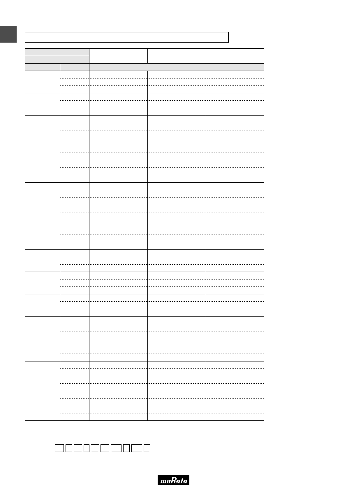
Temperature Compensating Type C0G(5C) Characteristics
LxW [mm]
Rated Volt. [Vdc]
Capacitance Tolerance Part Number
3.8pF(3R8)
3.9pF(3R9)
4.0pF(4R0)
4.1pF(4R1)
4.2pF(4R2)
4.3pF(4R3)
4.4pF(4R4)
4.5pF(4R5)
4.6pF(4R6)
4.7pF(4R7)
4.8pF(4R8)
4.9pF(4R9)
5.0pF(5R0)
5.1pF(5R1)
5.2pF(5R2)
The part number code is shown in ( ) and Unit is shown in [ ]. < >: EIA [inch] Code
±0.05pF(W)
±0.1pF(B)
±0.25pF(C)
±0.05pF(W)
±0.1pF(B)
±0.25pF(C)
±0.05pF(W)
±0.1pF(B)
±0.25pF(C)
±0.05pF(W)
±0.1pF(B)
±0.25pF(C)
±0.05pF(W)
±0.1pF(B)
±0.25pF(C)
±0.05pF(W)
±0.1pF(B)
±0.25pF(C)
±0.05pF(W)
±0.1pF(B)
±0.25pF(C)
±0.05pF(W)
±0.1pF(B)
±0.25pF(C)
±0.05pF(W)
±0.1pF(B)
±0.25pF(C)
±0.05pF(W)
±0.1pF(B)
±0.25pF(C)
±0.05pF(W)
±0.1pF(B)
±0.25pF(C)
±0.05pF(W)
±0.1pF(B)
±0.25pF(C)
±0.05pF(W)
±0.1pF(B)
±0.25pF(C)
±0.05pF(W)
±0.1pF(B)
±0.25pF(C)
±0.5pF(D)
±0.05pF(W)
±0.1pF(B)
±0.25pF(C)
±0.5pF(D)
0.4x0.2(02)<01005>
16(1C)
GRM0225C1C3R8WD05L
GRM0225C1C3R8BD05L
GRM0225C1C3R8CD05L
GRM0225C1C3R9WD05L
GRM0225C1C3R9BD05L
GRM0225C1C3R9CD05L
GRM0225C1C4R0WD05L
GRM0225C1C4R0BD05L
GRM0225C1C4R0CD05L
GRM0225C1C4R1WD05L
GRM0225C1C4R1BD05L
GRM0225C1C4R1CD05L
GRM0225C1C4R2WD05L
GRM0225C1C4R2BD05L
GRM0225C1C4R2CD05L
GRM0225C1C4R3WD05L
GRM0225C1C4R3BD05L
GRM0225C1C4R3CD05L
GRM0225C1C4R4WD05L
GRM0225C1C4R4BD05L
GRM0225C1C4R4CD05L
GRM0225C1C4R5WD05L
GRM0225C1C4R5BD05L
GRM0225C1C4R5CD05L
GRM0225C1C4R6WD05L
GRM0225C1C4R6BD05L
GRM0225C1C4R6CD05L
GRM0225C1C4R7WD05L
GRM0225C1C4R7BD05L
GRM0225C1C4R7CD05L
GRM0225C1C4R8WD05L
GRM0225C1C4R8BD05L
GRM0225C1C4R8CD05L
GRM0225C1C4R9WD05L
GRM0225C1C4R9BD05L
GRM0225C1C4R9CD05L
GRM0225C1C5R0WD05L
GRM0225C1C5R0BD05L
GRM0225C1C5R0CD05L
GRM0225C1C5R1WD05L
GRM0225C1C5R1BD05L
GRM0225C1C5R1CD05L
GRM0225C1C5R1DD05L
GRM0225C1C5R2WD05L
GRM0225C1C5R2BD05L
GRM0225C1C5R2CD05L
GRM0225C1C5R2DD05L
0.6x0.3(03)<0201>
50(1H)
GRM0335C1H3R8WD01D
GRM0335C1H3R8BD01D
GRM0335C1H3R8CD01D
GRM0335C1H3R9WD01D
GRM0335C1H3R9BD01D
GRM0335C1H3R9CD01D
GRM0335C1H4R0WD01D
GRM0335C1H4R0BD01D
GRM0335C1H4R0CD01D
GRM0335C1H4R1WD01D
GRM0335C1H4R1BD01D
GRM0335C1H4R1CD01D
GRM0335C1H4R2WD01D
GRM0335C1H4R2BD01D
GRM0335C1H4R2CD01D
GRM0335C1H4R3WD01D
GRM0335C1H4R3BD01D
GRM0335C1H4R3CD01D
GRM0335C1H4R4WD01D
GRM0335C1H4R4BD01D
GRM0335C1H4R4CD01D
GRM0335C1H4R5WD01D
GRM0335C1H4R5BD01D
GRM0335C1H4R5CD01D
GRM0335C1H4R6WD01D
GRM0335C1H4R6BD01D
GRM0335C1H4R6CD01D
GRM0335C1H4R7WD01D
GRM0335C1H4R7BD01D
GRM0335C1H4R7CD01D
GRM0335C1H4R8WD01D
GRM0335C1H4R8BD01D
GRM0335C1H4R8CD01D
GRM0335C1H4R9WD01D
GRM0335C1H4R9BD01D
GRM0335C1H4R9CD01D
GRM0335C1H5R0WD01D
GRM0335C1H5R0BD01D
GRM0335C1H5R0CD01D
GRM0335C1H5R1WD01D
GRM0335C1H5R1BD01D
GRM0335C1H5R1CD01D
GRM0335C1H5R1DD01D
GRM0335C1H5R2WD01D
GRM0335C1H5R2BD01D
GRM0335C1H5R2CD01D
GRM0335C1H5R2DD01D
GRM1555C1H3R8WA01D
GRM1555C1H3R8BA01D
GRM1555C1H3R8CA01D
GRM1555C1H3R9WA01D
GRM1555C1H3R9BA01D
GRM1555C1H3R9CA01D
GRM1555C1H4R0WA01D
GRM1555C1H4R0BA01D
GRM1555C1H4R0CA01D
GRM1555C1H4R1WA01D
GRM1555C1H4R1BA01D
GRM1555C1H4R1CA01D
GRM1555C1H4R2WA01D
GRM1555C1H4R2BA01D
GRM1555C1H4R2CA01D
GRM1555C1H4R3WA01D
GRM1555C1H4R3BA01D
GRM1555C1H4R3CA01D
GRM1555C1H4R4WA01D
GRM1555C1H4R4BA01D
GRM1555C1H4R4CA01D
GRM1555C1H4R5WA01D
GRM1555C1H4R5BA01D
GRM1555C1H4R5CA01D
GRM1555C1H4R6WA01D
GRM1555C1H4R6BA01D
GRM1555C1H4R6CA01D
GRM1555C1H4R7WA01D
GRM1555C1H4R7BA01D
GRM1555C1H4R7CA01D
GRM1555C1H4R8WA01D
GRM1555C1H4R8BA01D
GRM1555C1H4R8CA01D
GRM1555C1H4R9WA01D
GRM1555C1H4R9BA01D
GRM1555C1H4R9CA01D
GRM1555C1H5R0WA01D
GRM1555C1H5R0BA01D
GRM1555C1H5R0CA01D
GRM1555C1H5R1WA01D
GRM1555C1H5R1BA01D
GRM1555C1H5R1CA01D
GRM1555C1H5R1DA01D
GRM1555C1H5R2WA01D
GRM1555C1H5R2BA01D
GRM1555C1H5R2CA01D
GRM1555C1H5R2DA01D
1.0x0.5(15)<0402>
50(1H)
(Part Number)
Packaging Code in Part Number is a code shows STD 180mm Reel Taping.
GR M 02 2 5C 1C 3R8 W D05 L
e r t y u i o !0
wq
qProduct ID wSeries eDimension (LxW) rDimension (T)
tTemperature Characteristics yRated Voltage uCapacitance
iCapacitance Tolerance oIndividual Specification Code !0Packaging*
18
*GRM022: D is applicable.
Page 21
• This PDF catalog is downloaded from the website of Murata Manufacturing co., ltd. Therefore, it’s specifications are subject to change or our products in it may be discontinued without advance notice. Please check with our
!Note
• Please read rating and !CAUTION (for storage, operating, rating, soldering, mounting and handling) in this catalog to prevent smoking and/or burning, etc.
!Note
sales representatives or product engineers before ordering.
• This catalog has only typical specifications because there is no space for detailed specifications. Therefore, please approve our product specifications or transact the approval sheet for product specifications before ordering.
• This PDF catalog has only typical specifications because there is no space for detailed specifications. Therefore, please approve our product specifications or transact the approval sheet for product specifications before ordering.
C02E.pdf
09.9.18
Temperature Compensating Type C0G(5C) Characteristics
LxW [mm]
Rated Volt. [Vdc]
Capacitance Tolerance Part Number
5.3pF(5R3)
5.4pF(5R4)
5.5pF(5R5)
5.6pF(5R6)
5.7pF(5R7)
5.8pF(5R8)
5.9pF(5R9)
6.0pF(6R0)
6.1pF(6R1)
6.2pF(6R2)
6.3pF(6R3)
6.4pF(6R4)
6.5pF(6R5)
The part number code is shown in ( ) and Unit is shown in [ ]. < >: EIA [inch] Code
±0.05pF(W)
±0.1pF(B)
±0.25pF(C)
±0.5pF(D)
±0.05pF(W)
±0.1pF(B)
±0.25pF(C)
±0.5pF(D)
±0.05pF(W)
±0.1pF(B)
±0.25pF(C)
±0.5pF(D)
±0.05pF(W)
±0.1pF(B)
±0.25pF(C)
±0.5pF(D)
±0.05pF(W)
±0.1pF(B)
±0.25pF(C)
±0.5pF(D)
±0.05pF(W)
±0.1pF(B)
±0.25pF(C)
±0.5pF(D)
±0.05pF(W)
±0.1pF(B)
±0.25pF(C)
±0.5pF(D)
±0.05pF(W)
±0.1pF(B)
±0.25pF(C)
±0.5pF(D)
±0.05pF(W)
±0.1pF(B)
±0.25pF(C)
±0.5pF(D)
±0.05pF(W)
±0.1pF(B)
±0.25pF(C)
±0.5pF(D)
±0.05pF(W)
±0.1pF(B)
±0.25pF(C)
±0.5pF(D)
±0.05pF(W)
±0.1pF(B)
±0.25pF(C)
±0.5pF(D)
±0.05pF(W)
±0.1pF(B)
±0.25pF(C)
±0.5pF(D)
0.4x0.2(02)<01005>
16(1C)
GRM0225C1C5R3WD05L
GRM0225C1C5R3BD05L
GRM0225C1C5R3CD05L
GRM0225C1C5R3DD05L
GRM0225C1C5R4WD05L
GRM0225C1C5R4BD05L
GRM0225C1C5R4CD05L
GRM0225C1C5R4DD05L
GRM0225C1C5R5WD05L
GRM0225C1C5R5BD05L
GRM0225C1C5R5CD05L
GRM0225C1C5R5DD05L
GRM0225C1C5R6WD05L
GRM0225C1C5R6BD05L
GRM0225C1C5R6CD05L
GRM0225C1C5R6DD05L
GRM0225C1C5R7WD05L
GRM0225C1C5R7BD05L
GRM0225C1C5R7CD05L
GRM0225C1C5R7DD05L
GRM0225C1C5R8WD05L
GRM0225C1C5R8BD05L
GRM0225C1C5R8CD05L
GRM0225C1C5R8DD05L
GRM0225C1C5R9WD05L
GRM0225C1C5R9BD05L
GRM0225C1C5R9CD05L
GRM0225C1C5R9DD05L
GRM0225C1C6R0WD05L
GRM0225C1C6R0BD05L
GRM0225C1C6R0CD05L
GRM0225C1C6R0DD05L
GRM0225C1C6R1WD05L
GRM0225C1C6R1BD05L
GRM0225C1C6R1CD05L
GRM0225C1C6R1DD05L
GRM0225C1C6R2WD05L
GRM0225C1C6R2BD05L
GRM0225C1C6R2CD05L
GRM0225C1C6R2DD05L
GRM0225C1C6R3WD05L
GRM0225C1C6R3BD05L
GRM0225C1C6R3CD05L
GRM0225C1C6R3DD05L
GRM0225C1C6R4WD05L
GRM0225C1C6R4BD05L
GRM0225C1C6R4CD05L
GRM0225C1C6R4DD05L
GRM0225C1C6R5WD05L
GRM0225C1C6R5BD05L
GRM0225C1C6R5CD05L
GRM0225C1C6R5DD05L
0.6x0.3(03)<0201>
50(1H)
GRM0335C1H5R3WD01D
GRM0335C1H5R3BD01D
GRM0335C1H5R3CD01D
GRM0335C1H5R3DD01D
GRM0335C1H5R4WD01D
GRM0335C1H5R4BD01D
GRM0335C1H5R4CD01D
GRM0335C1H5R4DD01D
GRM0335C1H5R5WD01D
GRM0335C1H5R5BD01D
GRM0335C1H5R5CD01D
GRM0335C1H5R5DD01D
GRM0335C1H5R6WD01D
GRM0335C1H5R6BD01D
GRM0335C1H5R6CD01D
GRM0335C1H5R6DD01D
GRM0335C1H5R7WD01D
GRM0335C1H5R7BD01D
GRM0335C1H5R7CD01D
GRM0335C1H5R7DD01D
GRM0335C1H5R8WD01D
GRM0335C1H5R8BD01D
GRM0335C1H5R8CD01D
GRM0335C1H5R8DD01D
GRM0335C1H5R9WD01D
GRM0335C1H5R9BD01D
GRM0335C1H5R9CD01D
GRM0335C1H5R9DD01D
GRM0335C1H6R0WD01D
GRM0335C1H6R0BD01D
GRM0335C1H6R0CD01D
GRM0335C1H6R0DD01D
GRM0335C1H6R1WD01D
GRM0335C1H6R1BD01D
GRM0335C1H6R1CD01D
GRM0335C1H6R1DD01D
GRM0335C1H6R2WD01D
GRM0335C1H6R2BD01D
GRM0335C1H6R2CD01D
GRM0335C1H6R2DD01D
GRM0335C1H6R3WD01D
GRM0335C1H6R3BD01D
GRM0335C1H6R3CD01D
GRM0335C1H6R3DD01D
GRM0335C1H6R4WD01D
GRM0335C1H6R4BD01D
GRM0335C1H6R4CD01D
GRM0335C1H6R4DD01D
GRM0335C1H6R5WD01D
GRM0335C1H6R5BD01D
GRM0335C1H6R5CD01D
GRM0335C1H6R5DD01D
GRM1555C1H5R3WA01D
GRM1555C1H5R3BA01D
GRM1555C1H5R3CA01D
GRM1555C1H5R3DA01D
GRM1555C1H5R4WA01D
GRM1555C1H5R4BA01D
GRM1555C1H5R4CA01D
GRM1555C1H5R4DA01D
GRM1555C1H5R5WA01D
GRM1555C1H5R5BA01D
GRM1555C1H5R5CA01D
GRM1555C1H5R5DA01D
GRM1555C1H5R6WA01D
GRM1555C1H5R6BA01D
GRM1555C1H5R6CA01D
GRM1555C1H5R6DA01D
GRM1555C1H5R7WA01D
GRM1555C1H5R7BA01D
GRM1555C1H5R7CA01D
GRM1555C1H5R7DA01D
GRM1555C1H5R8WA01D
GRM1555C1H5R8BA01D
GRM1555C1H5R8CA01D
GRM1555C1H5R8DA01D
GRM1555C1H5R9WA01D
GRM1555C1H5R9BA01D
GRM1555C1H5R9CA01D
GRM1555C1H5R9DA01D
GRM1555C1H6R0WA01D
GRM1555C1H6R0BA01D
GRM1555C1H6R0CA01D
GRM1555C1H6R0DA01D
GRM1555C1H6R1WA01D
GRM1555C1H6R1BA01D
GRM1555C1H6R1CA01D
GRM1555C1H6R1DA01D
GRM1555C1H6R2WA01D
GRM1555C1H6R2BA01D
GRM1555C1H6R2CA01D
GRM1555C1H6R2DA01D
GRM1555C1H6R3WA01D
GRM1555C1H6R3BA01D
GRM1555C1H6R3CA01D
GRM1555C1H6R3DA01D
GRM1555C1H6R4WA01D
GRM1555C1H6R4BA01D
GRM1555C1H6R4CA01D
GRM1555C1H6R4DA01D
GRM1555C1H6R5WA01D
GRM1555C1H6R5BA01D
GRM1555C1H6R5CA01D
GRM1555C1H6R5DA01D
1
1.0x0.5(15)<0402>
50(1H)
19
Page 22
• This PDF catalog is downloaded from the website of Murata Manufacturing co., ltd. Therefore, it’s specifications are subject to change or our products in it may be discontinued without advance notice. Please check with our
!Note
• Please read rating and !CAUTION (for storage, operating, rating, soldering, mounting and handling) in this catalog to prevent smoking and/or burning, etc.
!Note
sales representatives or product engineers before ordering.
• This catalog has only typical specifications because there is no space for detailed specifications. Therefore, please approve our product specifications or transact the approval sheet for product specifications before ordering.
• This PDF catalog has only typical specifications because there is no space for detailed specifications. Therefore, please approve our product specifications or transact the approval sheet for product specifications before ordering.
C02E.pdf
09.9.18
1
Temperature Compensating Type C0G(5C) Characteristics
LxW [mm]
Rated Volt. [Vdc]
Capacitance Tolerance Part Number
6.6pF(6R6)
6.7pF(6R7)
6.8pF(6R8)
6.9pF(6R9)
7.0pF(7R0)
7.1pF(7R1)
7.2pF(7R2)
7.3pF(7R3)
7.4pF(7R4)
7.5pF(7R5)
7.6pF(7R6)
7.7pF(7R7)
The part number code is shown in ( ) and Unit is shown in [ ]. < >: EIA [inch] Code
±0.05pF(W)
±0.1pF(B)
±0.25pF(C)
±0.5pF(D)
±0.05pF(W)
±0.1pF(B)
±0.25pF(C)
±0.5pF(D)
±0.05pF(W)
±0.1pF(B)
±0.25pF(C)
±0.5pF(D)
±0.05pF(W)
±0.1pF(B)
±0.25pF(C)
±0.5pF(D)
±0.05pF(W)
±0.1pF(B)
±0.25pF(C)
±0.5pF(D)
±0.05pF(W)
±0.1pF(B)
±0.25pF(C)
±0.5pF(D)
±0.05pF(W)
±0.1pF(B)
±0.25pF(C)
±0.5pF(D)
±0.05pF(W)
±0.1pF(B)
±0.25pF(C)
±0.5pF(D)
±0.05pF(W)
±0.1pF(B)
±0.25pF(C)
±0.5pF(D)
±0.05pF(W)
±0.1pF(B)
±0.25pF(C)
±0.5pF(D)
±0.05pF(W)
±0.1pF(B)
±0.25pF(C)
±0.5pF(D)
±0.05pF(W)
±0.1pF(B)
±0.25pF(C)
±0.5pF(D)
0.4x0.2(02)<01005>
16(1C)
GRM0225C1C6R6WD05L
GRM0225C1C6R6BD05L
GRM0225C1C6R6CD05L
GRM0225C1C6R6DD05L
GRM0225C1C6R7WD05L
GRM0225C1C6R7BD05L
GRM0225C1C6R7CD05L
GRM0225C1C6R7DD05L
GRM0225C1C6R8WD05L
GRM0225C1C6R8BD05L
GRM0225C1C6R8CD05L
GRM0225C1C6R8DD05L
GRM0225C1C6R9WD05L
GRM0225C1C6R9BD05L
GRM0225C1C6R9CD05L
GRM0225C1C6R9DD05L
GRM0225C1C7R0WD05L
GRM0225C1C7R0BD05L
GRM0225C1C7R0CD05L
GRM0225C1C7R0DD05L
GRM0225C1C7R1WD05L
GRM0225C1C7R1BD05L
GRM0225C1C7R1CD05L
GRM0225C1C7R1DD05L
GRM0225C1C7R2WD05L
GRM0225C1C7R2BD05L
GRM0225C1C7R2CD05L
GRM0225C1C7R2DD05L
GRM0225C1C7R3WD05L
GRM0225C1C7R3BD05L
GRM0225C1C7R3CD05L
GRM0225C1C7R3DD05L
GRM0225C1C7R4WD05L
GRM0225C1C7R4BD05L
GRM0225C1C7R4CD05L
GRM0225C1C7R4DD05L
GRM0225C1C7R5WD05L
GRM0225C1C7R5BD05L
GRM0225C1C7R5CD05L
GRM0225C1C7R5DD05L
GRM0225C1C7R6WD05L
GRM0225C1C7R6BD05L
GRM0225C1C7R6CD05L
GRM0225C1C7R6DD05L
GRM0225C1C7R7WD05L
GRM0225C1C7R7BD05L
GRM0225C1C7R7CD05L
GRM0225C1C7R7DD05L
0.6x0.3(03)<0201>
50(1H)
GRM0335C1H6R6WD01D
GRM0335C1H6R6BD01D
GRM0335C1H6R6CD01D
GRM0335C1H6R6DD01D
GRM0335C1H6R7WD01D
GRM0335C1H6R7BD01D
GRM0335C1H6R7CD01D
GRM0335C1H6R7DD01D
GRM0335C1H6R8WD01D
GRM0335C1H6R8BD01D
GRM0335C1H6R8CD01D
GRM0335C1H6R8DD01D
GRM0335C1H6R9WD01D
GRM0335C1H6R9BD01D
GRM0335C1H6R9CD01D
GRM0335C1H6R9DD01D
GRM0335C1H7R0WD01D
GRM0335C1H7R0BD01D
GRM0335C1H7R0CD01D
GRM0335C1H7R0DD01D
GRM0335C1H7R1WD01D
GRM0335C1H7R1BD01D
GRM0335C1H7R1CD01D
GRM0335C1H7R1DD01D
GRM0335C1H7R2WD01D
GRM0335C1H7R2BD01D
GRM0335C1H7R2CD01D
GRM0335C1H7R2DD01D
GRM0335C1H7R3WD01D
GRM0335C1H7R3BD01D
GRM0335C1H7R3CD01D
GRM0335C1H7R3DD01D
GRM0335C1H7R4WD01D
GRM0335C1H7R4BD01D
GRM0335C1H7R4CD01D
GRM0335C1H7R4DD01D
GRM0335C1H7R5WD01D
GRM0335C1H7R5BD01D
GRM0335C1H7R5CD01D
GRM0335C1H7R5DD01D
GRM0335C1H7R6WD01D
GRM0335C1H7R6BD01D
GRM0335C1H7R6CD01D
GRM0335C1H7R6DD01D
GRM0335C1H7R7WD01D
GRM0335C1H7R7BD01D
GRM0335C1H7R7CD01D
GRM0335C1H7R7DD01D
GRM1555C1H6R6WA01D
GRM1555C1H6R6BA01D
GRM1555C1H6R6CA01D
GRM1555C1H6R6DA01D
GRM1555C1H6R7WA01D
GRM1555C1H6R7BA01D
GRM1555C1H6R7CA01D
GRM1555C1H6R7DA01D
GRM1555C1H6R8WA01D
GRM1555C1H6R8BA01D
GRM1555C1H6R8CA01D
GRM1555C1H6R8DA01D
GRM1555C1H6R9WA01D
GRM1555C1H6R9BA01D
GRM1555C1H6R9CA01D
GRM1555C1H6R9DA01D
GRM1555C1H7R0WA01D
GRM1555C1H7R0BA01D
GRM1555C1H7R0CA01D
GRM1555C1H7R0DA01D
GRM1555C1H7R1WA01D
GRM1555C1H7R1BA01D
GRM1555C1H7R1CA01D
GRM1555C1H7R1DA01D
GRM1555C1H7R2WA01D
GRM1555C1H7R2BA01D
GRM1555C1H7R2CA01D
GRM1555C1H7R2DA01D
GRM1555C1H7R3WA01D
GRM1555C1H7R3BA01D
GRM1555C1H7R3CA01D
GRM1555C1H7R3DA01D
GRM1555C1H7R4WA01D
GRM1555C1H7R4BA01D
GRM1555C1H7R4CA01D
GRM1555C1H7R4DA01D
GRM1555C1H7R5WA01D
GRM1555C1H7R5BA01D
GRM1555C1H7R5CA01D
GRM1555C1H7R5DA01D
GRM1555C1H7R6WA01D
GRM1555C1H7R6BA01D
GRM1555C1H7R6CA01D
GRM1555C1H7R6DA01D
GRM1555C1H7R7WA01D
GRM1555C1H7R7BA01D
GRM1555C1H7R7CA01D
GRM1555C1H7R7DA01D
1.0x0.5(15)<0402>
50(1H)
(Part Number)
Packaging Code in Part Number is a code shows STD 180mm Reel Taping.
GR M 02 2 5C 1C 6R6 W D05 L
e r t y u i o !0
wq
qProduct ID wSeries eDimension (LxW) rDimension (T)
tTemperature Characteristics yRated Voltage uCapacitance
iCapacitance Tolerance oIndividual Specification Code !0Packaging*
20
*GRM022: D is applicable.
Page 23
• This PDF catalog is downloaded from the website of Murata Manufacturing co., ltd. Therefore, it’s specifications are subject to change or our products in it may be discontinued without advance notice. Please check with our
!Note
• Please read rating and !CAUTION (for storage, operating, rating, soldering, mounting and handling) in this catalog to prevent smoking and/or burning, etc.
!Note
sales representatives or product engineers before ordering.
• This catalog has only typical specifications because there is no space for detailed specifications. Therefore, please approve our product specifications or transact the approval sheet for product specifications before ordering.
• This PDF catalog has only typical specifications because there is no space for detailed specifications. Therefore, please approve our product specifications or transact the approval sheet for product specifications before ordering.
C02E.pdf
09.9.18
Temperature Compensating Type C0G(5C) Characteristics
LxW [mm]
Rated Volt. [Vdc]
Capacitance Tolerance Part Number
7.8pF(7R8)
7.9pF(7R9)
8.0pF(8R0)
8.1pF(8R1)
8.2pF(8R2)
8.3pF(8R3)
8.4pF(8R4)
8.5pF(8R5)
8.6pF(8R6)
8.7pF(8R7)
8.8pF(8R8)
8.9pF(8R9)
9.0pF(9R0)
The part number code is shown in ( ) and Unit is shown in [ ]. < >: EIA [inch] Code
±0.05pF(W)
±0.1pF(B)
±0.25pF(C)
±0.5pF(D)
±0.05pF(W)
±0.1pF(B)
±0.25pF(C)
±0.5pF(D)
±0.05pF(W)
±0.1pF(B)
±0.25pF(C)
±0.5pF(D)
±0.05pF(W)
±0.1pF(B)
±0.25pF(C)
±0.5pF(D)
±0.05pF(W)
±0.1pF(B)
±0.25pF(C)
±0.5pF(D)
±0.05pF(W)
±0.1pF(B)
±0.25pF(C)
±0.5pF(D)
±0.05pF(W)
±0.1pF(B)
±0.25pF(C)
±0.5pF(D)
±0.05pF(W)
±0.1pF(B)
±0.25pF(C)
±0.5pF(D)
±0.05pF(W)
±0.1pF(B)
±0.25pF(C)
±0.5pF(D)
±0.05pF(W)
±0.1pF(B)
±0.25pF(C)
±0.5pF(D)
±0.05pF(W)
±0.1pF(B)
±0.25pF(C)
±0.5pF(D)
±0.05pF(W)
±0.1pF(B)
±0.25pF(C)
±0.5pF(D)
±0.05pF(W)
±0.1pF(B)
±0.25pF(C)
±0.5pF(D)
0.4x0.2(02)<01005>
16(1C)
GRM0225C1C7R8WD05L
GRM0225C1C7R8BD05L
GRM0225C1C7R8CD05L
GRM0225C1C7R8DD05L
GRM0225C1C7R9WD05L
GRM0225C1C7R9BD05L
GRM0225C1C7R9CD05L
GRM0225C1C7R9DD05L
GRM0225C1C8R0WD05L
GRM0225C1C8R0BD05L
GRM0225C1C8R0CD05L
GRM0225C1C8R0DD05L
GRM0225C1C8R1WD05L
GRM0225C1C8R1BD05L
GRM0225C1C8R1CD05L
GRM0225C1C8R1DD05L
GRM0225C1C8R2WD05L
GRM0225C1C8R2BD05L
GRM0225C1C8R2CD05L
GRM0225C1C8R2DD05L
GRM0225C1C8R3WD05L
GRM0225C1C8R3BD05L
GRM0225C1C8R3CD05L
GRM0225C1C8R3DD05L
GRM0225C1C8R4WD05L
GRM0225C1C8R4BD05L
GRM0225C1C8R4CD05L
GRM0225C1C8R4DD05L
GRM0225C1C8R5WD05L
GRM0225C1C8R5BD05L
GRM0225C1C8R5CD05L
GRM0225C1C8R5DD05L
GRM0225C1C8R6WD05L
GRM0225C1C8R6BD05L
GRM0225C1C8R6CD05L
GRM0225C1C8R6DD05L
GRM0225C1C8R7WD05L
GRM0225C1C8R7BD05L
GRM0225C1C8R7CD05L
GRM0225C1C8R7DD05L
GRM0225C1C8R8WD05L
GRM0225C1C8R8BD05L
GRM0225C1C8R8CD05L
GRM0225C1C8R8DD05L
GRM0225C1C8R9WD05L
GRM0225C1C8R9BD05L
GRM0225C1C8R9CD05L
GRM0225C1C8R9DD05L
GRM0225C1C9R0WD05L
GRM0225C1C9R0BD05L
GRM0225C1C9R0CD05L
GRM0225C1C9R0DD05L
0.6x0.3(03)<0201>
50(1H)
GRM0335C1H7R8WD01D
GRM0335C1H7R8BD01D
GRM0335C1H7R8CD01D
GRM0335C1H7R8DD01D
GRM0335C1H7R9WD01D
GRM0335C1H7R9BD01D
GRM0335C1H7R9CD01D
GRM0335C1H7R9DD01D
GRM0335C1H8R0WD01D
GRM0335C1H8R0BD01D
GRM0335C1H8R0CD01D
GRM0335C1H8R0DD01D
GRM0335C1H8R1WD01D
GRM0335C1H8R1BD01D
GRM0335C1H8R1CD01D
GRM0335C1H8R1DD01D
GRM0335C1H8R2WD01D
GRM0335C1H8R2BD01D
GRM0335C1H8R2CD01D
GRM0335C1H8R2DD01D
GRM0335C1H8R3WD01D
GRM0335C1H8R3BD01D
GRM0335C1H8R3CD01D
GRM0335C1H8R3DD01D
GRM0335C1H8R4WD01D
GRM0335C1H8R4BD01D
GRM0335C1H8R4CD01D
GRM0335C1H8R4DD01D
GRM0335C1H8R5WD01D
GRM0335C1H8R5BD01D
GRM0335C1H8R5CD01D
GRM0335C1H8R5DD01D
GRM0335C1H8R6WD01D
GRM0335C1H8R6BD01D
GRM0335C1H8R6CD01D
GRM0335C1H8R6DD01D
GRM0335C1H8R7WD01D
GRM0335C1H8R7BD01D
GRM0335C1H8R7CD01D
GRM0335C1H8R7DD01D
GRM0335C1H8R8WD01D
GRM0335C1H8R8BD01D
GRM0335C1H8R8CD01D
GRM0335C1H8R8DD01D
GRM0335C1H8R9WD01D
GRM0335C1H8R9BD01D
GRM0335C1H8R9CD01D
GRM0335C1H8R9DD01D
GRM0335C1H9R0WD01D
GRM0335C1H9R0BD01D
GRM0335C1H9R0CD01D
GRM0335C1H9R0DD01D
GRM1555C1H7R8WA01D
GRM1555C1H7R8BA01D
GRM1555C1H7R8CA01D
GRM1555C1H7R8DA01D
GRM1555C1H7R9WA01D
GRM1555C1H7R9BA01D
GRM1555C1H7R9CA01D
GRM1555C1H7R9DA01D
GRM1555C1H8R0WA01D
GRM1555C1H8R0BA01D
GRM1555C1H8R0CA01D
GRM1555C1H8R0DA01D
GRM1555C1H8R1WA01D
GRM1555C1H8R1BA01D
GRM1555C1H8R1CA01D
GRM1555C1H8R1DA01D
GRM1555C1H8R2WA01D
GRM1555C1H8R2BA01D
GRM1555C1H8R2CA01D
GRM1555C1H8R2DA01D
GRM1555C1H8R3WA01D
GRM1555C1H8R3BA01D
GRM1555C1H8R3CA01D
GRM1555C1H8R3DA01D
GRM1555C1H8R4WA01D
GRM1555C1H8R4BA01D
GRM1555C1H8R4CA01D
GRM1555C1H8R4DA01D
GRM1555C1H8R5WA01D
GRM1555C1H8R5BA01D
GRM1555C1H8R5CA01D
GRM1555C1H8R5DA01D
GRM1555C1H8R6WA01D
GRM1555C1H8R6BA01D
GRM1555C1H8R6CA01D
GRM1555C1H8R6DA01D
GRM1555C1H8R7WA01D
GRM1555C1H8R7BA01D
GRM1555C1H8R7CA01D
GRM1555C1H8R7DA01D
GRM1555C1H8R8WA01D
GRM1555C1H8R8BA01D
GRM1555C1H8R8CA01D
GRM1555C1H8R8DA01D
GRM1555C1H8R9WA01D
GRM1555C1H8R9BA01D
GRM1555C1H8R9CA01D
GRM1555C1H8R9DA01D
GRM1555C1H9R0WA01D
GRM1555C1H9R0BA01D
GRM1555C1H9R0CA01D
GRM1555C1H9R0DA01D
1
1.0x0.5(15)<0402>
50(1H)
21
Page 24
• This PDF catalog is downloaded from the website of Murata Manufacturing co., ltd. Therefore, it’s specifications are subject to change or our products in it may be discontinued without advance notice. Please check with our
!Note
• Please read rating and !CAUTION (for storage, operating, rating, soldering, mounting and handling) in this catalog to prevent smoking and/or burning, etc.
!Note
sales representatives or product engineers before ordering.
• This catalog has only typical specifications because there is no space for detailed specifications. Therefore, please approve our product specifications or transact the approval sheet for product specifications before ordering.
• This PDF catalog has only typical specifications because there is no space for detailed specifications. Therefore, please approve our product specifications or transact the approval sheet for product specifications before ordering.
C02E.pdf
09.9.18
1
Temperature Compensating Type C0G(5C) Characteristics
LxW [mm]
Rated Volt. [Vdc]
Capacitance Tolerance Part Number
9.1pF(9R1)
9.2pF(9R2)
9.3pF(9R3)
9.4pF(9R4)
9.5pF(9R5)
9.6pF(9R6)
9.7pF(9R7)
9.8pF(9R8)
9.9pF(9R9)
The part number code is shown in ( ) and Unit is shown in [ ]. < >: EIA [inch] Code
±0.05pF(W)
±0.1pF(B)
±0.25pF(C)
±0.5pF(D)
±0.05pF(W)
±0.1pF(B)
±0.25pF(C)
±0.5pF(D)
±0.05pF(W)
±0.1pF(B)
±0.25pF(C)
±0.5pF(D)
±0.05pF(W)
±0.1pF(B)
±0.25pF(C)
±0.5pF(D)
±0.05pF(W)
±0.1pF(B)
±0.25pF(C)
±0.5pF(D)
±0.05pF(W)
±0.1pF(B)
±0.25pF(C)
±0.5pF(D)
±0.05pF(W)
±0.1pF(B)
±0.25pF(C)
±0.5pF(D)
±0.05pF(W)
±0.1pF(B)
±0.25pF(C)
±0.5pF(D)
±0.05pF(W)
±0.1pF(B)
±0.25pF(C)
±0.5pF(D)
GRM0225C1C9R1WD05L
GRM0225C1C9R1BD05L
GRM0225C1C9R1CD05L
GRM0225C1C9R1DD05L
GRM0225C1C9R2WD05L
GRM0225C1C9R2BD05L
GRM0225C1C9R2CD05L
GRM0225C1C9R2DD05L
GRM0225C1C9R3WD05L
GRM0225C1C9R3BD05L
GRM0225C1C9R3CD05L
GRM0225C1C9R3DD05L
GRM0225C1C9R4WD05L
GRM0225C1C9R4BD05L
GRM0225C1C9R4CD05L
GRM0225C1C9R4DD05L
GRM0225C1C9R5WD05L
GRM0225C1C9R5BD05L
GRM0225C1C9R5CD05L
GRM0225C1C9R5DD05L
GRM0225C1C9R6WD05L
GRM0225C1C9R6BD05L
GRM0225C1C9R6CD05L
GRM0225C1C9R6DD05L
GRM0225C1C9R7WD05L
GRM0225C1C9R7BD05L
GRM0225C1C9R7CD05L
GRM0225C1C9R7DD05L
GRM0225C1C9R8WD05L
GRM0225C1C9R8BD05L
GRM0225C1C9R8CD05L
GRM0225C1C9R8DD05L
GRM0225C1C9R9WD05L
GRM0225C1C9R9BD05L
GRM0225C1C9R9CD05L
GRM0225C1C9R9DD05L
16(1C)
0.6x0.3(03)<0201> 1.0x0.5(15)<0402>0.4x0.2(02)<01005>
50(1H)
GRM0335C1H9R1WD01D
GRM0335C1H9R1BD01D
GRM0335C1H9R1CD01D
GRM0335C1H9R1DD01D
GRM0335C1H9R2WD01D
GRM0335C1H9R2BD01D
GRM0335C1H9R2CD01D
GRM0335C1H9R2DD01D
GRM0335C1H9R3WD01D
GRM0335C1H9R3BD01D
GRM0335C1H9R3CD01D
GRM0335C1H9R3DD01D
GRM0335C1H9R4WD01D
GRM0335C1H9R4BD01D
GRM0335C1H9R4CD01D
GRM0335C1H9R4DD01D
GRM0335C1H9R5WD01D
GRM0335C1H9R5BD01D
GRM0335C1H9R5CD01D
GRM0335C1H9R5DD01D
GRM0335C1H9R6WD01D
GRM0335C1H9R6BD01D
GRM0335C1H9R6CD01D
GRM0335C1H9R6DD01D
GRM0335C1H9R7WD01D
GRM0335C1H9R7BD01D
GRM0335C1H9R7CD01D
GRM0335C1H9R7DD01D
GRM0335C1H9R8WD01D
GRM0335C1H9R8BD01D
GRM0335C1H9R8CD01D
GRM0335C1H9R8DD01D
GRM0335C1H9R9WD01D
GRM0335C1H9R9BD01D
GRM0335C1H9R9CD01D
GRM0335C1H9R9DD01D
GRM1555C1H9R1WA01D
GRM1555C1H9R1BA01D
GRM1555C1H9R1CA01D
GRM1555C1H9R1DA01D
GRM1555C1H9R2WA01D
GRM1555C1H9R2BA01D
GRM1555C1H9R2CA01D
GRM1555C1H9R2DA01D
GRM1555C1H9R3WA01D
GRM1555C1H9R3BA01D
GRM1555C1H9R3CA01D
GRM1555C1H9R3DA01D
GRM1555C1H9R4WA01D
GRM1555C1H9R4BA01D
GRM1555C1H9R4CA01D
GRM1555C1H9R4DA01D
GRM1555C1H9R5WA01D
GRM1555C1H9R5BA01D
GRM1555C1H9R5CA01D
GRM1555C1H9R5DA01D
GRM1555C1H9R6WA01D
GRM1555C1H9R6BA01D
GRM1555C1H9R6CA01D
GRM1555C1H9R6DA01D
GRM1555C1H9R7WA01D
GRM1555C1H9R7BA01D
GRM1555C1H9R7CA01D
GRM1555C1H9R7DA01D
GRM1555C1H9R8WA01D
GRM1555C1H9R8BA01D
GRM1555C1H9R8CA01D
GRM1555C1H9R8DA01D
GRM1555C1H9R9WA01D
GRM1555C1H9R9BA01D
GRM1555C1H9R9CA01D
GRM1555C1H9R9DA01D
50(1H)
(Part Number)
Packaging Code in Part Number is a code shows STD 180mm Reel Taping.
GR M 02 2 5C 1C 9R1 W D05 L
e r t y u i o !0
wq
qProduct ID wSeries eDimension (LxW) rDimension (T)
tTemperature Characteristics yRated Voltage uCapacitance
iCapacitance Tolerance oIndividual Specification Code !0Packaging*
22
*GRM022: D is applicable.
Page 25
• This PDF catalog is downloaded from the website of Murata Manufacturing co., ltd. Therefore, it’s specifications are subject to change or our products in it may be discontinued without advance notice. Please check with our
!Note
• Please read rating and !CAUTION (for storage, operating, rating, soldering, mounting and handling) in this catalog to prevent smoking and/or burning, etc.
!Note
sales representatives or product engineers before ordering.
• This catalog has only typical specifications because there is no space for detailed specifications. Therefore, please approve our product specifications or transact the approval sheet for product specifications before ordering.
• This PDF catalog has only typical specifications because there is no space for detailed specifications. Therefore, please approve our product specifications or transact the approval sheet for product specifications before ordering.
C02E.pdf
09.9.18
Temperature Compensating Type C0G(5C) Characteristics
LxW [mm]
Rated Volt. [Vdc]
Capacitance Tolerance Part Number
10pF(100)
12pF(120)
15pF(150)
18pF(180)
22pF(220)
27pF(270)
33pF(330)
39pF(390)
47pF(470)
56pF(560)
68pF(680)
82pF(820)
100pF(101)
The part number code is shown in ( ) and Unit is shown in [ ]. < >: EIA [inch] Code
±2%(G)
±5%(J)
±2%(G)
±5%(J)
±2%(G)
±5%(J)
±2%(G)
±5%(J)
±2%(G)
±5%(J)
±2%(G)
±5%(J)
±2%(G)
±5%(J)
±2%(G)
±5%(J)
±2%(G)
±5%(J)
±2%(G)
±5%(J)
±2%(G)
±5%(J)
±2%(G)
±5%(J)
±2%(G)
±5%(J)
GRM0225C1C100GD05L
GRM0225C1C100JD05L
GRM0225C1C120GD05L
GRM0225C1C120JD05L
GRM0225C1C150GD05L
GRM0225C1C150JD05L
GRM0225C1C180GD05L
GRM0225C1C180JD05L
GRM0225C1C220GD05L
GRM0225C1C220JD05L
GRM0225C1C270GD05L
GRM0225C1C270JD05L
GRM0225C1C330GD05L
GRM0225C1C330JD05L
GRM0225C1C390GD05L
GRM0225C1C390JD05L
GRM0225C1C470GD05L
GRM0225C1C470JD05L
16(1C)
0.4x0.2(02)<01005> 0.6x0.3(03)<0201>
10(1A)
GRM0225C1A560GD05L
GRM0225C1A560JD05L
GRM0225C1A680GD05L
GRM0225C1A680JD05L
GRM0225C1A820GD05L
GRM0225C1A820JD05L
GRM0225C1A101GD05L
GRM0225C1A101JD05L
GRM0225C0J560GD05L
GRM0225C0J560JD05L
GRM0225C0J680GD05L
GRM0225C0J680JD05L
GRM0225C0J820GD05L
GRM0225C0J820JD05L
GRM0225C0J101GD05L
GRM0225C0J101JD05L
6.3(0J)
1
50(1H)
GRM0335C1H100GD01D
GRM0335C1H100JD01D
GRM0335C1H120GD01D
GRM0335C1H120JD01D
GRM0335C1H150GD01D
GRM0335C1H150JD01D
GRM0335C1H180GD01D
GRM0335C1H180JD01D
GRM0335C1H220GD01D
GRM0335C1H220JD01D
GRM0335C1H270GD01D
GRM0335C1H270JD01D
GRM0335C1H330GD01D
GRM0335C1H330JD01D
GRM0335C1H390GD01D
GRM0335C1H390JD01D
GRM0335C1H470GD01D
GRM0335C1H470JD01D
GRM0335C1H560GD01D
GRM0335C1H560JD01D
GRM0335C1H680GD01D
GRM0335C1H680JD01D
GRM0335C1H820GD01D
GRM0335C1H820JD01D
GRM0335C1H101GD01D
GRM0335C1H101JD01D
23
Page 26
• This PDF catalog is downloaded from the website of Murata Manufacturing co., ltd. Therefore, it’s specifications are subject to change or our products in it may be discontinued without advance notice. Please check with our
!Note
• Please read rating and !CAUTION (for storage, operating, rating, soldering, mounting and handling) in this catalog to prevent smoking and/or burning, etc.
!Note
sales representatives or product engineers before ordering.
• This catalog has only typical specifications because there is no space for detailed specifications. Therefore, please approve our product specifications or transact the approval sheet for product specifications before ordering.
• This PDF catalog has only typical specifications because there is no space for detailed specifications. Therefore, please approve our product specifications or transact the approval sheet for product specifications before ordering.
C02E.pdf
09.9.18
1
Temperature Compensating Type C0G(5C) Characteristics
LxW [mm]
Rated Volt. [Vdc]
TC
Capacitance Tolerance Part Number
10pF(100)
12pF(120)
15pF(150)
18pF(180)
22pF(220)
27pF(270)
33pF(330)
39pF(390)
47pF(470)
56pF(560)
68pF(680)
82pF(820)
100pF(101)
120pF(121)
150pF(151)
180pF(181)
220pF(221)
270pF(271)
330pF(331)
390pF(391)
470pF(471)
560pF(561)
680pF(681)
820pF(821)
1000pF(102)
The part number code is shown in ( ) and Unit is shown in [ ]. < >: EIA [inch] Code
(Part Number)
Packaging Code in Part Number is a code shows STD 180mm Reel Taping.
±2%(G)
±5%(J)
±2%(G)
±5%(J)
±2%(G)
±5%(J)
±2%(G)
±5%(J)
±2%(G)
±5%(J)
±2%(G)
±5%(J)
±2%(G)
±5%(J)
±2%(G)
±5%(J)
±2%(G)
±5%(J)
±2%(G)
±5%(J)
±2%(G)
±5%(J)
±2%(G)
±5%(J)
±2%(G)
±5%(J)
±2%(G)
±5%(J)
±2%(G)
±5%(J)
±2%(G)
±5%(J)
±2%(G)
±5%(J)
±2%(G)
±5%(J)
±2%(G)
±5%(J)
±2%(G)
±5%(J)
±2%(G)
±5%(J)
±2%(G)
±5%(J)
±2%(G)
±5%(J)
±2%(G)
±5%(J)
±2%(G)
±5%(J)
GR M 15 5 5C 1H 100 G Z01 D
e r t y u i o !0
wq
1.0x0.5(15)<0402>
50(1H)
C0G(5C)
GRM1555C1H100GA01D
GRM1555C1H100JA01D
GRM1555C1H120GA01D
GRM1555C1H120JA01D
GRM1555C1H150GA01D
GRM1555C1H150JA01D
GRM1555C1H180GA01D
GRM1555C1H180JA01D
GRM1555C1H220GA01D
GRM1555C1H220JA01D
GRM1555C1H270GA01D
GRM1555C1H270JA01D
GRM1555C1H330GA01D
GRM1555C1H330JA01D
GRM1555C1H390GA01D
GRM1555C1H390JA01D
GRM1555C1H470GA01D
GRM1555C1H470JA01D
GRM1555C1H560GA01D
GRM1555C1H560JA01D
GRM1555C1H680GA01D
GRM1555C1H680JA01D
GRM1555C1H820GA01D
GRM1555C1H820JA01D
GRM1555C1H101GA01D
GRM1555C1H101JA01D
GRM1555C1H121GA01D
GRM1555C1H121JA01D
GRM1555C1H151GA01D
GRM1555C1H151JA01D
GRM1555C1H181GA01D
GRM1555C1H181JA01D
GRM1555C1H221GA01D
GRM1555C1H221JA01D
GRM1555C1H271GA01D
GRM1555C1H271JA01D
GRM1555C1H331GA01D
GRM1555C1H331JA01D
GRM1555C1H391GA01D
GRM1555C1H391JA01D
GRM1555C1H471GA01D
GRM1555C1H471JA01D
GRM1555C1H561GA01D
GRM1555C1H561JA01D
GRM1555C1H681GA01D
GRM1555C1H681JA01D
GRM1555C1H821GA01D
GRM1555C1H821JA01D
GRM1555C1H102GA01D
GRM1555C1H102JA01D
qProduct ID wSeries eDimension (LxW) rDimension (T)
tTemperature Characteristics yRated Voltage uCapacitance
iCapacitance Tolerance oIndividual Specification Code !0Packaging
24
Page 27
• This PDF catalog is downloaded from the website of Murata Manufacturing co., ltd. Therefore, it’s specifications are subject to change or our products in it may be discontinued without advance notice. Please check with our
!Note
• Please read rating and !CAUTION (for storage, operating, rating, soldering, mounting and handling) in this catalog to prevent smoking and/or burning, etc.
!Note
sales representatives or product engineers before ordering.
• This catalog has only typical specifications because there is no space for detailed specifications. Therefore, please approve our product specifications or transact the approval sheet for product specifications before ordering.
• This PDF catalog has only typical specifications because there is no space for detailed specifications. Therefore, please approve our product specifications or transact the approval sheet for product specifications before ordering.
C02E.pdf
09.9.18
Temperature Compensating Type C0G(5C) Characteristics
LxW [mm]
Rated Volt. [Vdc]
Capacitance Tolerance Part Number
10pF(100)
12pF(120)
15pF(150)
18pF(180)
22pF(220)
27pF(270)
33pF(330)
39pF(390)
47pF(470)
56pF(560)
68pF(680)
82pF(820)
100pF(101)
120pF(121)
150pF(151)
180pF(181)
220pF(221)
270pF(271)
330pF(331)
390pF(391)
470pF(471)
560pF(561)
680pF(681)
820pF(821)
1000pF(102)
1200pF(122)
1500pF(152)
1800pF(182)
2200pF(222)
2700pF(272)
3300pF(332)
3900pF(392)
The part number code is shown in ( ) and Unit is shown in [ ]. < >: EIA [inch] Code
±5%(J)
±5%(J)
±5%(J)
±5%(J)
±5%(J)
±5%(J)
±5%(J)
±5%(J)
±5%(J)
±5%(J)
±5%(J)
±5%(J)
±5%(J)
±5%(J)
±5%(J)
±5%(J)
±5%(J)
±5%(J)
±5%(J)
±5%(J)
±5%(J)
±5%(J)
±5%(J)
±5%(J)
±5%(J)
±5%(J)
±5%(J)
±5%(J)
±5%(J)
±5%(J)
±5%(J)
±5%(J)
100(2A)
GRM1885C2A100JA01D
GRM1885C2A120JA01D
GRM1885C2A150JA01D
GRM1885C2A180JA01D
GRM1885C2A220JA01D
GRM1885C2A270JA01D
GRM1885C2A330JA01D
GRM1885C2A390JA01D
GRM1885C2A470JA01D
GRM1885C2A560JA01D
GRM1885C2A680JA01D
GRM1885C2A820JA01D
GRM1885C2A101JA01D
GRM1885C2A121JA01D
GRM1885C2A151JA01D
GRM1885C2A181JA01D
GRM1885C2A221JA01D
GRM1885C2A271JA01D
GRM1885C2A331JA01D
GRM1885C2A391JA01D
GRM1885C2A471JA01D
GRM1885C2A561JA01D
GRM1885C2A681JA01D
GRM1885C2A821JA01D
GRM1885C2A102JA01D
GRM1885C2A122JA01D
GRM1885C2A152JA01D
1.6x0.8(18)<0603>
50(1H)
GRM1885C1H100JA01D
GRM1885C1H120JA01D
GRM1885C1H150JA01D
GRM1885C1H180JA01D
GRM1885C1H220JA01D
GRM1885C1H270JA01D
GRM1885C1H330JA01D
GRM1885C1H390JA01D
GRM1885C1H470JA01D
GRM1885C1H560JA01D
GRM1885C1H680JA01D
GRM1885C1H820JA01D
GRM1885C1H101JA01D
GRM1885C1H121JA01D
GRM1885C1H151JA01D
GRM1885C1H181JA01D
GRM1885C1H221JA01D
GRM1885C1H271JA01D
GRM1885C1H331JA01D
GRM1885C1H391JA01D
GRM1885C1H471JA01D
GRM1885C1H561JA01D
GRM1885C1H681JA01D
GRM1885C1H821JA01D
GRM1885C1H102JA01D
GRM1885C1H122JA01D
GRM1885C1H152JA01D
GRM1885C1H182JA01D
GRM1885C1H222JA01D
GRM1885C1H272JA01D
GRM1885C1H332JA01D
GRM1885C1H392JA01D
1
25
Page 28
• This PDF catalog is downloaded from the website of Murata Manufacturing co., ltd. Therefore, it’s specifications are subject to change or our products in it may be discontinued without advance notice. Please check with our
!Note
• Please read rating and !CAUTION (for storage, operating, rating, soldering, mounting and handling) in this catalog to prevent smoking and/or burning, etc.
!Note
sales representatives or product engineers before ordering.
• This catalog has only typical specifications because there is no space for detailed specifications. Therefore, please approve our product specifications or transact the approval sheet for product specifications before ordering.
• This PDF catalog has only typical specifications because there is no space for detailed specifications. Therefore, please approve our product specifications or transact the approval sheet for product specifications before ordering.
C02E.pdf
09.9.18
1
Temperature Compensating Type C0G(5C) Characteristics
LxW [mm]
Rated Volt. [Vdc]
Capacitance Tolerance Part Number
100pF(101)
120pF(121)
150pF(151)
180pF(181)
220pF(221)
270pF(271)
330pF(331)
390pF(391)
470pF(471)
560pF(561)
680pF(681)
820pF(821)
1000pF(102)
1200pF(122)
1500pF(152)
1800pF(182)
2200pF(222)
2700pF(272)
3300pF(332)
3900pF(392)
4700pF(472)
5600pF(562)
6800pF(682)
8200pF(822)
10000pF(103)
12000pF(123)
15000pF(153)
18000pF(183)
22000pF(223)
27000pF(273)
33000pF(333)
39000pF(393)
47000pF(473)
56000pF(563)
68000pF(683)
82000pF(823)
100000pF(104)
The part number code is shown in ( ) and Unit is shown in [ ]. < >: EIA [inch] Code
±5%(J)
±5%(J)
±5%(J)
±5%(J)
±5%(J)
±5%(J)
±5%(J)
±5%(J)
±5%(J)
±5%(J)
±5%(J)
±5%(J)
±5%(J)
±5%(J)
±5%(J)
±5%(J)
±5%(J)
±5%(J)
±5%(J)
±5%(J)
±5%(J)
±5%(J)
±5%(J)
±5%(J)
±5%(J)
±5%(J)
±5%(J)
±5%(J)
±5%(J)
±5%(J)
±5%(J)
±5%(J)
±5%(J)
±5%(J)
±5%(J)
±5%(J)
±5%(J)
GRM2165C2A101JA01D
GRM2165C2A121JA01D
GRM2165C2A151JA01D
GRM2165C2A181JA01D
GRM2165C2A221JA01D
GRM2165C2A271JA01D
GRM2165C2A331JA01D
GRM2165C2A391JA01D
GRM2165C2A471JA01D
GRM2165C2A561JA01D
GRM2165C2A681JA01D
GRM2165C2A821JA01D
GRM2165C2A102JA01D
GRM2165C2A122JA01D
GRM2165C2A152JA01D
GRM2165C2A182JA01D
GRM2165C2A222JA01D
GRM2165C2A272JA01D
GRM2165C2A332JA01D
2.0x1.25(21)<0805> 3.2x1.6(31)<1206>
100(2A)
GRM2165C1H122JA01D
GRM2165C1H152JA01D
GRM2165C1H182JA01D
GRM2165C1H222JA01D
GRM2165C1H272JA01D
GRM2165C1H332JA01D
GRM2165C1H392JA01D
GRM2165C1H472JA01D
GRM2195C1H562JA01D
GRM2195C1H682JA01D
GRM2195C1H822JA01D
GRM2195C1H103JA01D
GRM2195C1H123JA01D
GRM2195C1H153JA01D
GRM21B5C1H183JA01L
GRM21B5C1H223JA01L
50(1H)
GRM3195C2A182JA01D
GRM3195C2A222JA01D
GRM3195C2A272JA01D
GRM3195C2A332JA01D
GRM3195C2A392JA01D
GRM3195C2A472JA01D
GRM3195C2A562JA01D
GRM3195C2A682JA01D
GRM3195C2A822JA01D
GRM3195C2A103JA01D
100(2A)
50(1H)
GRM3195C1H472JA01D
GRM3195C1H562JA01D
GRM3195C1H682JA01D
GRM3195C1H822JA01D
GRM3195C1H103JA01D
GRM3195C1H123JA01D
GRM3195C1H153JA01D
GRM3195C1H183JA01D
GRM3195C1H223JA01D
GRM3195C1H273JA01D
GRM3195C1H333JA01D
GRM3195C1H393JA01D
GRM31M5C1H473JA01L
GRM31M5C1H563JA01L
GRM31C5C1H683JA01L
GRM31C5C1H823JA01L
GRM31C5C1H104JA01L
(Part Number)
Packaging Code in Part Number is a code shows STD 180mm Reel Taping.
GR M 21 6 5C 2A 101 J A01 D
e r t y u i o !0
wq
qProduct ID wSeries eDimension (LxW) rDimension (T)
tTemperature Characteristics yRated Voltage uCapacitance
iCapacitance Tolerance oIndividual Specification Code !0Packaging
26
Page 29
• This PDF catalog is downloaded from the website of Murata Manufacturing co., ltd. Therefore, it’s specifications are subject to change or our products in it may be discontinued without advance notice. Please check with our
!Note
• Please read rating and !CAUTION (for storage, operating, rating, soldering, mounting and handling) in this catalog to prevent smoking and/or burning, etc.
!Note
sales representatives or product engineers before ordering.
• This catalog has only typical specifications because there is no space for detailed specifications. Therefore, please approve our product specifications or transact the approval sheet for product specifications before ordering.
• This PDF catalog has only typical specifications because there is no space for detailed specifications. Therefore, please approve our product specifications or transact the approval sheet for product specifications before ordering.
C02E.pdf
09.9.18
Temperature Compensating Type C0G(5C) Characteristics Low Profile
LxW [mm]
Rated Volt. [Vdc]
Capacitance Tolerance Part Number
0.1pF(R10)
0.2pF(R20)
0.3pF(R30)
0.4pF(R40)
0.5pF(R50)
0.6pF(R60)
0.7pF(R70)
0.8pF(R80)
0.9pF(R90)
1.0pF(1R0)
1.1pF(1R1)
1.2pF(1R2)
1.3pF(1R3)
1.4pF(1R4)
1.5pF(1R5)
1.6pF(1R6)
1.7pF(1R7)
1.8pF(1R8)
1.9pF(1R9)
2.0pF(2R0)
2.1pF(2R1)
2.2pF(2R2)
2.3pF(2R3)
2.4pF(2R4)
2.5pF(2R5)
2.6pF(2R6)
2.7pF(2R7)
2.8pF(2R8)
2.9pF(2R9)
3.0pF(3R0)
3.1pF(3R1)
3.2pF(3R2)
3.3pF(3R3)
3.4pF(3R4)
3.5pF(3R5)
3.6pF(3R6)
3.7pF(3R7)
3.8pF(3R8)
3.9pF(3R9)
4.0pF(4R0)
4.1pF(4R1)
4.2pF(4R2)
4.3pF(4R3)
4.4pF(4R4)
4.5pF(4R5)
4.6pF(4R6)
4.7pF(4R7)
4.8pF(4R8)
4.9pF(4R9)
5.0pF(5R0)
The part number code is shown in ( ) and Unit is shown in [ ]. < >: EIA [inch] Code
±0.1pF(B)
±0.1pF(B)
±0.1pF(B)
±0.1pF(B)
±0.1pF(B)
±0.1pF(B)
±0.1pF(B)
±0.1pF(B)
±0.1pF(B)
±0.25pF(C)
±0.25pF(C)
±0.25pF(C)
±0.25pF(C)
±0.25pF(C)
±0.25pF(C)
±0.25pF(C)
±0.25pF(C)
±0.25pF(C)
±0.25pF(C)
±0.25pF(C)
±0.25pF(C)
±0.25pF(C)
±0.25pF(C)
±0.25pF(C)
±0.25pF(C)
±0.25pF(C)
±0.25pF(C)
±0.25pF(C)
±0.25pF(C)
±0.25pF(C)
±0.25pF(C)
±0.25pF(C)
±0.25pF(C)
±0.25pF(C)
±0.25pF(C)
±0.25pF(C)
±0.25pF(C)
±0.25pF(C)
±0.25pF(C)
±0.25pF(C)
±0.25pF(C)
±0.25pF(C)
±0.25pF(C)
±0.25pF(C)
±0.25pF(C)
±0.25pF(C)
±0.25pF(C)
±0.25pF(C)
±0.25pF(C)
±0.25pF(C)
1.0x0.5(15)<0402>
50(1H)
GRM1535C1HR10BDD5D
GRM1535C1HR20BDD5D
GRM1535C1HR30BDD5D
GRM1535C1HR40BDD5D
GRM1535C1HR50BDD5D
GRM1535C1HR60BDD5D
GRM1535C1HR70BDD5D
GRM1535C1HR80BDD5D
GRM1535C1HR90BDD5D
GRM1535C1H1R0CDD5D
GRM1535C1H1R1CDD5D
GRM1535C1H1R2CDD5D
GRM1535C1H1R3CDD5D
GRM1535C1H1R4CDD5D
GRM1535C1H1R5CDD5D
GRM1535C1H1R6CDD5D
GRM1535C1H1R7CDD5D
GRM1535C1H1R8CDD5D
GRM1535C1H1R9CDD5D
GRM1535C1H2R0CDD5D
GRM1535C1H2R1CDD5D
GRM1535C1H2R2CDD5D
GRM1535C1H2R3CDD5D
GRM1535C1H2R4CDD5D
GRM1535C1H2R5CDD5D
GRM1535C1H2R6CDD5D
GRM1535C1H2R7CDD5D
GRM1535C1H2R8CDD5D
GRM1535C1H2R9CDD5D
GRM1535C1H3R0CDD5D
GRM1535C1H3R1CDD5D
GRM1535C1H3R2CDD5D
GRM1535C1H3R3CDD5D
GRM1535C1H3R4CDD5D
GRM1535C1H3R5CDD5D
GRM1535C1H3R6CDD5D
GRM1535C1H3R7CDD5D
GRM1535C1H3R8CDD5D
GRM1535C1H3R9CDD5D
GRM1535C1H4R0CDD5D
GRM1535C1H4R1CDD5D
GRM1535C1H4R2CDD5D
GRM1535C1H4R3CDD5D
GRM1535C1H4R4CDD5D
GRM1535C1H4R5CDD5D
GRM1535C1H4R6CDD5D
GRM1535C1H4R7CDD5D
GRM1535C1H4R8CDD5D
GRM1535C1H4R9CDD5D
GRM1535C1H5R0CDD5D
LxW [mm]
Rated Volt. [Vdc]
Capacitance Tolerance Part Number
5.1pF(5R1)
5.2pF(5R2)
5.3pF(5R3)
5.4pF(5R4)
5.5pF(5R5)
5.6pF(5R6)
5.7pF(5R7)
5.8pF(5R8)
5.9pF(5R9)
6.0pF(6R0)
6.1pF(6R1)
6.2pF(6R2)
6.3pF(6R3)
6.4pF(6R4)
6.5pF(6R5)
6.6pF(6R6)
6.7pF(6R7)
6.8pF(6R8)
6.9pF(6R9)
7.0pF(7R0)
7.1pF(7R1)
7.2pF(7R2)
7.3pF(7R3)
7.4pF(7R4)
7.5pF(7R5)
7.6pF(7R6)
7.7pF(7R7)
7.8pF(7R8)
7.9pF(7R9)
8.0pF(8R0)
8.1pF(8R1)
8.2pF(8R2)
8.3pF(8R3)
8.4pF(8R4)
8.5pF(8R5)
8.6pF(8R6)
8.7pF(8R7)
8.8pF(8R8)
8.9pF(8R9)
9.0pF(9R0)
9.1pF(9R1)
9.2pF(9R2)
9.3pF(9R3)
9.4pF(9R4)
9.5pF(9R5)
9.6pF(9R6)
9.7pF(9R7)
9.8pF(9R8)
9.9pF(9R9)
±0.5pF(D)
±0.5pF(D)
±0.5pF(D)
±0.5pF(D)
±0.5pF(D)
±0.5pF(D)
±0.5pF(D)
±0.5pF(D)
±0.5pF(D)
±0.5pF(D)
±0.5pF(D)
±0.5pF(D)
±0.5pF(D)
±0.5pF(D)
±0.5pF(D)
±0.5pF(D)
±0.5pF(D)
±0.5pF(D)
±0.5pF(D)
±0.5pF(D)
±0.5pF(D)
±0.5pF(D)
±0.5pF(D)
±0.5pF(D)
±0.5pF(D)
±0.5pF(D)
±0.5pF(D)
±0.5pF(D)
±0.5pF(D)
±0.5pF(D)
±0.5pF(D)
±0.5pF(D)
±0.5pF(D)
±0.5pF(D)
±0.5pF(D)
±0.5pF(D)
±0.5pF(D)
±0.5pF(D)
±0.5pF(D)
±0.5pF(D)
±0.5pF(D)
±0.5pF(D)
±0.5pF(D)
±0.5pF(D)
±0.5pF(D)
±0.5pF(D)
±0.5pF(D)
±0.5pF(D)
±0.5pF(D)
1.0x0.5(15)<0402>
GRM1535C1H5R1DDD5D
GRM1535C1H5R2DDD5D
GRM1535C1H5R3DDD5D
GRM1535C1H5R4DDD5D
GRM1535C1H5R5DDD5D
GRM1535C1H5R6DDD5D
GRM1535C1H5R7DDD5D
GRM1535C1H5R8DDD5D
GRM1535C1H5R9DDD5D
GRM1535C1H6R0DDD5D
GRM1535C1H6R1DDD5D
GRM1535C1H6R2DDD5D
GRM1535C1H6R3DDD5D
GRM1535C1H6R4DDD5D
GRM1535C1H6R5DDD5D
GRM1535C1H6R6DDD5D
GRM1535C1H6R7DDD5D
GRM1535C1H6R8DDD5D
GRM1535C1H6R9DDD5D
GRM1535C1H7R0DDD5D
GRM1535C1H7R1DDD5D
GRM1535C1H7R2DDD5D
GRM1535C1H7R3DDD5D
GRM1535C1H7R4DDD5D
GRM1535C1H7R5DDD5D
GRM1535C1H7R6DDD5D
GRM1535C1H7R7DDD5D
GRM1535C1H7R8DDD5D
GRM1535C1H7R9DDD5D
GRM1535C1H8R0DDD5D
GRM1535C1H8R1DDD5D
GRM1535C1H8R2DDD5D
GRM1535C1H8R3DDD5D
GRM1535C1H8R4DDD5D
GRM1535C1H8R5DDD5D
GRM1535C1H8R6DDD5D
GRM1535C1H8R7DDD5D
GRM1535C1H8R8DDD5D
GRM1535C1H8R9DDD5D
GRM1535C1H9R0DDD5D
GRM1535C1H9R1DDD5D
GRM1535C1H9R2DDD5D
GRM1535C1H9R3DDD5D
GRM1535C1H9R4DDD5D
GRM1535C1H9R5DDD5D
GRM1535C1H9R6DDD5D
GRM1535C1H9R7DDD5D
GRM1535C1H9R8DDD5D
GRM1535C1H9R9DDD5D
1
50(1H)
27
Page 30
• This PDF catalog is downloaded from the website of Murata Manufacturing co., ltd. Therefore, it’s specifications are subject to change or our products in it may be discontinued without advance notice. Please check with our
!Note
• Please read rating and !CAUTION (for storage, operating, rating, soldering, mounting and handling) in this catalog to prevent smoking and/or burning, etc.
!Note
sales representatives or product engineers before ordering.
• This catalog has only typical specifications because there is no space for detailed specifications. Therefore, please approve our product specifications or transact the approval sheet for product specifications before ordering.
• This PDF catalog has only typical specifications because there is no space for detailed specifications. Therefore, please approve our product specifications or transact the approval sheet for product specifications before ordering.
C02E.pdf
09.9.18
1
Temperature Compensating Type C0G(5C) Characteristics Low Profile
LxW [mm]
Rated Volt. [Vdc]
1.0x0.5(15)<0402>
50(1H)
Capacitance Tolerance Part Number
10pF(100)
12pF(120)
15pF(150)
18pF(180)
22pF(220)
27pF(270)
33pF(330)
39pF(390)
47pF(470)
56pF(560)
68pF(680)
82pF(820)
100pF(101)
120pF(121)
150pF(151)
180pF(181)
220pF(221)
270pF(271)
330pF(331)
390pF(391)
470pF(471)
560pF(561)
680pF(681)
The part number code is shown in ( ) and Unit is shown in [ ]. < >: EIA [inch] Code
±5%(J)
±5%(J)
±5%(J)
±5%(J)
±5%(J)
±5%(J)
±5%(J)
±5%(J)
±5%(J)
±5%(J)
±5%(J)
±5%(J)
±5%(J)
±5%(J)
±5%(J)
±5%(J)
±5%(J)
±5%(J)
±5%(J)
±5%(J)
±5%(J)
±5%(J)
±5%(J)
GRM1535C1H100JDD5D
GRM1535C1H120JDD5D
GRM1535C1H150JDD5D
GRM1535C1H180JDD5D
GRM1535C1H220JDD5D
GRM1535C1H270JDD5D
GRM1535C1H330JDD5D
GRM1535C1H390JDD5D
GRM1535C1H470JDD5D
GRM1535C1H560JDD5D
GRM1535C1H680JDD5D
GRM1535C1H820JDD5D
GRM1535C1H101JDD5D
GRM1535C1H121JDD5D
GRM1535C1H151JDD5D
GRM1535C1H181JDD5D
GRM1535C1H221JDD5D
GRM1535C1H271JDD5D
GRM1535C1H331JDD5D
GRM1535C1H391JDD5D
GRM1535C1H471JDD5D
GRM1535C1H561JDD5D
GRM1535C1H681JDD5D
(Part Number)
GR M 15 3 5C 1H 100 J DD5 D
e r t y u i o !0
wq
qProduct ID wSeries eDimension (LxW) rDimension (T)
tTemperature Characteristics yRated Voltage uCapacitance
iCapacitance Tolerance oIndividual Specification Code !0Packaging
Packaging Code in Part Number is a code shows STD 180mm Reel Taping.
28
Page 31

• This PDF catalog is downloaded from the website of Murata Manufacturing co., ltd. Therefore, it’s specifications are subject to change or our products in it may be discontinued without advance notice. Please check with our
!Note
• Please read rating and !CAUTION (for storage, operating, rating, soldering, mounting and handling) in this catalog to prevent smoking and/or burning, etc.
!Note
sales representatives or product engineers before ordering.
• This catalog has only typical specifications because there is no space for detailed specifications. Therefore, please approve our product specifications or transact the approval sheet for product specifications before ordering.
• This PDF catalog has only typical specifications because there is no space for detailed specifications. Therefore, please approve our product specifications or transact the approval sheet for product specifications before ordering.
C02E.pdf
09.9.18
Temperature Compensating Type C0G(5C) Characteristics Low Profile
LxW [mm]
Rated Volt. [Vdc]
Capacitance Tolerance Part Number
100pF(101)
120pF(121)
150pF(151)
180pF(181)
220pF(221)
270pF(271)
330pF(331)
390pF(391)
470pF(471)
560pF(561)
680pF(681)
820pF(821)
1000pF(102)
1200pF(122)
1500pF(152)
1800pF(182)
2200pF(222)
2700pF(272)
3300pF(332)
3900pF(392)
4700pF(472)
5600pF(562)
6800pF(682)
8200pF(822)
10000pF(103)
12000pF(123)
15000pF(153)
18000pF(183)
22000pF(223)
27000pF(273)
33000pF(333)
39000pF(393)
47000pF(473)
56000pF(563)
The part number code is shown in ( ) and Unit is shown in [ ]. < >: EIA [inch] Code
±5%(J)
±5%(J)
±5%(J)
±5%(J)
±5%(J)
±5%(J)
±5%(J)
±5%(J)
±5%(J)
±5%(J)
±5%(J)
±5%(J)
±5%(J)
±5%(J)
±5%(J)
±5%(J)
±5%(J)
±5%(J)
±5%(J)
±5%(J)
±5%(J)
±5%(J)
±5%(J)
±5%(J)
±5%(J)
±5%(J)
±5%(J)
±5%(J)
±5%(J)
±5%(J)
±5%(J)
±5%(J)
±5%(J)
±5%(J)
GRM2165C2A101JA01D
GRM2165C2A121JA01D
GRM2165C2A151JA01D
GRM2165C2A181JA01D
GRM2165C2A221JA01D
GRM2165C2A271JA01D
GRM2165C2A331JA01D
GRM2165C2A391JA01D
GRM2165C2A471JA01D
GRM2165C2A561JA01D
GRM2165C2A681JA01D
GRM2165C2A821JA01D
GRM2165C2A102JA01D
GRM2165C2A122JA01D
GRM2165C2A152JA01D
GRM2165C2A182JA01D
GRM2165C2A222JA01D
GRM2165C2A272JA01D
GRM2165C2A332JA01D
2.0x1.25(21)<0805> 3.2x1.6(31)<1206>
100(2A)
GRM2165C1H122JA01D
GRM2165C1H152JA01D
GRM2165C1H182JA01D
GRM2165C1H222JA01D
GRM2165C1H272JA01D
GRM2165C1H332JA01D
GRM2165C1H392JA01D
GRM2165C1H472JA01D
GRM2195C1H562JA01D
GRM2195C1H682JA01D
GRM2195C1H822JA01D
GRM2195C1H103JA01D
GRM2195C1H123JA01D
GRM2195C1H153JA01D
50(1H)
100(2A)
GRM3195C2A182JA01D
GRM3195C2A222JA01D
GRM3195C2A272JA01D
GRM3195C2A332JA01D
GRM3195C2A392JA01D
GRM3195C2A472JA01D
GRM3195C2A562JA01D
GRM3195C2A682JA01D
GRM3195C2A822JA01D
GRM3195C2A103JA01D
1
50(1H)
GRM3195C1H472JA01D
GRM3195C1H562JA01D
GRM3195C1H682JA01D
GRM3195C1H822JA01D
GRM3195C1H103JA01D
GRM3195C1H123JA01D
GRM3195C1H153JA01D
GRM3195C1H183JA01D
GRM3195C1H223JA01D
GRM3195C1H273JA01D
GRM3195C1H333JA01D
GRM3195C1H393JA01D
GRM31M5C1H473JA01L
GRM31M5C1H563JA01L
29
Page 32
• This PDF catalog is downloaded from the website of Murata Manufacturing co., ltd. Therefore, it’s specifications are subject to change or our products in it may be discontinued without advance notice. Please check with our
!Note
• Please read rating and !CAUTION (for storage, operating, rating, soldering, mounting and handling) in this catalog to prevent smoking and/or burning, etc.
!Note
sales representatives or product engineers before ordering.
• This catalog has only typical specifications because there is no space for detailed specifications. Therefore, please approve our product specifications or transact the approval sheet for product specifications before ordering.
• This PDF catalog has only typical specifications because there is no space for detailed specifications. Therefore, please approve our product specifications or transact the approval sheet for product specifications before ordering.
C02E.pdf
09.9.18
1
Temperature Compensating Type U2J(7U) Characteristics
LxW [mm]
Rated Volt. [Vdc]
Capacitance Tolerance Part Number
1.0pF(1R0)
2.0pF(2R0)
3.0pF(3R0)
4.0pF(4R0)
5.0pF(5R0)
6.0pF(6R0)
7.0pF(7R0)
8.0pF(8R0)
9.0pF(9R0)
10pF(100)
12pF(120)
15pF(150)
18pF(180)
22pF(220)
27pF(270)
33pF(330)
39pF(390)
47pF(470)
56pF(560)
68pF(680)
82pF(820)
100pF(101)
120pF(121)
150pF(151)
180pF(181)
1200pF(122)
1500pF(152)
1800pF(182)
2200pF(222)
2700pF(272)
3300pF(332)
3900pF(392)
4700pF(472)
The part number code is shown in ( ) and Unit is shown in [ ]. < >: EIA [inch] Code
±0.25pF(C)
±0.25pF(C)
±0.25pF(C)
±0.25pF(C)
±0.25pF(C)
±0.5pF(D)
±0.5pF(D)
±0.5pF(D)
±0.5pF(D)
±5%(J)
±5%(J)
±5%(J)
±5%(J)
±5%(J)
±5%(J)
±5%(J)
±5%(J)
±5%(J)
±5%(J)
±5%(J)
±5%(J)
±5%(J)
±5%(J)
±5%(J)
±5%(J)
±5%(J)
±5%(J)
±5%(J)
±5%(J)
±5%(J)
±5%(J)
±5%(J)
±5%(J)
GRM0337U1H1R0CD01D
GRM0337U1H2R0CD01D
GRM0337U1H3R0CD01D
GRM0337U1H4R0CD01D
GRM0337U1H5R0CD01D
GRM0337U1H6R0DD01D
GRM0337U1H7R0DD01D
GRM0337U1H8R0DD01D
GRM0337U1H9R0DD01D
GRM0337U1H100JD01D
GRM0337U1H120JD01D
GRM0337U1H150JD01D
0.6x0.3(03)<0201> 1.0x0.5(15)<0402>
50(1H)
GRM0337U1E180JD01D
GRM0337U1E220JD01D
GRM0337U1E270JD01D
GRM0337U1E330JD01D
GRM0337U1E390JD01D
GRM0337U1E470JD01D
GRM0337U1E560JD01D
GRM0337U1E680JD01D
GRM0337U1E820JD01D
GRM0337U1E101JD01D
25(1E)
GRM1557U1H1R0CZ01D
GRM1557U1H2R0CZ01D
GRM1557U1H3R0CZ01D
GRM1557U1H4R0CZ01D
GRM1557U1H5R0CZ01D
GRM1557U1H6R0DZ01D
GRM1557U1H7R0DZ01D
GRM1557U1H8R0DZ01D
GRM1557U1H9R0DZ01D
GRM1557U1H100JZ01D
GRM1557U1H120JZ01D
GRM1557U1H150JZ01D
GRM1557U1H180JZ01D
GRM1557U1H220JZ01D
GRM1557U1H270JZ01D
GRM1557U1H330JZ01D
GRM1557U1H390JZ01D
GRM1557U1H470JZ01D
GRM1557U1H560JZ01D
GRM1557U1H680JZ01D
GRM1557U1H820JZ01D
GRM1557U1H101JZ01D
GRM1557U1H121JZ01D
GRM1557U1H151JZ01D
GRM1557U1H181JZ01D
50(1H)
10(1A)
GRM1557U1A122JA01D
GRM1557U1A152JA01D
GRM1557U1A182JA01D
GRM1557U1A222JA01D
GRM1557U1A272JA01D
GRM1557U1A332JA01D
GRM1557U1A392JA01D
GRM1557U1A472JA01D
(Part Number)
Packaging Code in Part Number is a code shows STD 180mm Reel Taping.
GR M 03 3 7U 1H 1R0 C D01 D
e r t y u i o !0
wq
qProduct ID wSeries eDimension (LxW) rDimension (T)
tTemperature Characteristics yRated Voltage uCapacitance
iCapacitance Tolerance oIndividual Specification Code !0Packaging
30
Page 33

• This PDF catalog is downloaded from the website of Murata Manufacturing co., ltd. Therefore, it’s specifications are subject to change or our products in it may be discontinued without advance notice. Please check with our
!Note
• Please read rating and !CAUTION (for storage, operating, rating, soldering, mounting and handling) in this catalog to prevent smoking and/or burning, etc.
!Note
sales representatives or product engineers before ordering.
• This catalog has only typical specifications because there is no space for detailed specifications. Therefore, please approve our product specifications or transact the approval sheet for product specifications before ordering.
• This PDF catalog has only typical specifications because there is no space for detailed specifications. Therefore, please approve our product specifications or transact the approval sheet for product specifications before ordering.
C02E.pdf
09.9.18
Temperature Compensating Type U2J(7U) Characteristics
LxW [mm]
Rated Volt. [Vdc]
Capacitance Tolerance Part Number
1000pF(102)
1200pF(122)
1500pF(152)
1800pF(182)
2200pF(222)
2700pF(272)
3300pF(332)
3900pF(392)
4700pF(472)
5600pF(562)
6800pF(682)
8200pF(822)
10000pF(103)
12000pF(123)
15000pF(153)
18000pF(183)
22000pF(223)
±5%(J)
±5%(J)
±5%(J)
±5%(J)
±5%(J)
±5%(J)
±5%(J)
±5%(J)
±5%(J)
±5%(J)
±5%(J)
±5%(J)
±5%(J)
±5%(J)
±5%(J)
±5%(J)
±5%(J)
GRM1887U1H102JA01D
GRM1887U1H122JA01D
GRM1887U1H152JA01D
GRM1887U1H182JA01D
GRM1887U1H222JA01D
GRM1887U1H272JA01D
GRM1887U1H332JA01D
GRM1887U1H392JA01D
GRM1887U1H472JA01D
GRM1887U1H562JA01D
GRM1887U1H682JA01D
GRM1887U1H822JA01D
GRM1887U1H103JA01D
1.6x0.8(18)<0603>
50(1H)
10(1A)
GRM1887U1A123JA01D
GRM1887U1A153JA01D
GRM1887U1A183JA01D
GRM1887U1A223JA01D
1
LxW [mm]
Rated Volt. [Vdc]
Capacitance Tolerance Part Number
10000pF(103)
12000pF(123)
15000pF(153)
18000pF(183)
22000pF(223)
27000pF(273)
33000pF(333)
39000pF(393)
47000pF(473)
56000pF(563)
68000pF(683)
82000pF(823)
100000pF(104)
The part number code is shown in ( ) and Unit is shown in [ ]. < >: EIA [inch] Code
±5%(J)
±5%(J)
±5%(J)
±5%(J)
±5%(J)
±5%(J)
±5%(J)
±5%(J)
±5%(J)
±5%(J)
±5%(J)
±5%(J)
±5%(J)
GRM2167U1H103JA01D
GRM2167U1H123JA01D
GRM2167U1H153JA01D
GRM2167U1H183JA01D
GRM2197U1H223JA01D
GRM2197U1H273JA01D
GRM21A7U1H333JA39L
GRM21B7U1H393JA01L
GRM21B7U1H473JA01L
2.0x1.25(21)<0805> 3.2x1.6(31)<1206>
50(1H)
GRM2197U1A563JA01D
GRM21B7U1A683JA01L
GRM21B7U1A823JA01L
GRM21B7U1A104JA01L
10(1A)
50(1H)
GRM3197U1H563JA01D
GRM31M7U1H683JA01L
GRM31M7U1H823JA01L
GRM31M7U1H104JA01L
31
Page 34
• This PDF catalog is downloaded from the website of Murata Manufacturing co., ltd. Therefore, it’s specifications are subject to change or our products in it may be discontinued without advance notice. Please check with our
!Note
• Please read rating and !CAUTION (for storage, operating, rating, soldering, mounting and handling) in this catalog to prevent smoking and/or burning, etc.
!Note
sales representatives or product engineers before ordering.
• This catalog has only typical specifications because there is no space for detailed specifications. Therefore, please approve our product specifications or transact the approval sheet for product specifications before ordering.
• This PDF catalog has only typical specifications because there is no space for detailed specifications. Therefore, please approve our product specifications or transact the approval sheet for product specifications before ordering.
C02E.pdf
09.9.18
1
Temperature Compensating Type U2J(7U) Characteristics Low Profile
LxW [mm]
Rated Volt. [Vdc]
Capacitance Tolerance Part Number
2200pF(222)
2700pF(272)
3300pF(332)
3900pF(392)
4700pF(472)
5600pF(562)
6800pF(682)
8200pF(822)
10000pF(103)
LxW [mm]
Rated Volt. [Vdc]
Capacitance Tolerance Part Number
10000pF(103)
12000pF(123)
15000pF(153)
18000pF(183)
22000pF(223)
27000pF(273)
33000pF(333)
56000pF(563)
68000pF(683)
82000pF(823)
100000pF(104)
The part number code is shown in ( ) and Unit is shown in [ ]. < >: EIA [inch] Code
±5%(J)
±5%(J)
±5%(J)
±5%(J)
±5%(J)
±5%(J)
±5%(J)
±5%(J)
±5%(J)
±5%(J)
±5%(J)
±5%(J)
±5%(J)
±5%(J)
±5%(J)
±5%(J)
±5%(J)
±5%(J)
±5%(J)
±5%(J)
GRM1857U1H222JA44D
GRM1857U1H272JA44D
GRM1857U1H332JA44D
GRM1857U1H392JA44D
GRM1857U1H472JA44D
GRM2167U1H103JA01D
GRM2167U1H123JA01D
GRM2167U1H153JA01D
GRM2167U1H183JA01D
GRM2197U1H223JA01D
GRM2197U1H273JA01D
GRM21A7U1H333JA39L
1.6x0.8(18)<0603>
50(1H)
GRM1857U1A562JA44D
GRM1857U1A682JA44D
GRM1857U1A822JA44D
GRM1857U1A103JA44D
10(1A)
2.0x1.25(21)<0805> 3.2x1.6(31)<1206>
50(1H)
GRM2197U1A563JA01D
10(1A)
GRM3197U1H563JA01D
GRM31M7U1H683JA01L
GRM31M7U1H823JA01L
GRM31M7U1H104JA01L
50(1H)
(Part Number)
Packaging Code in Part Number is a code shows STD 180mm Reel Taping.
GR M 18 5 7U 1H 222 J A44 D
e r t y u i o !0
wq
qProduct ID wSeries eDimension (LxW) rDimension (T)
tTemperature Characteristics yRated Voltage uCapacitance
iCapacitance Tolerance oIndividual Specification Code !0Packaging
32
Page 35

• This PDF catalog is downloaded from the website of Murata Manufacturing co., ltd. Therefore, it’s specifications are subject to change or our products in it may be discontinued without advance notice. Please check with our
!Note
• Please read rating and !CAUTION (for storage, operating, rating, soldering, mounting and handling) in this catalog to prevent smoking and/or burning, etc.
!Note
sales representatives or product engineers before ordering.
• This catalog has only typical specifications because there is no space for detailed specifications. Therefore, please approve our product specifications or transact the approval sheet for product specifications before ordering.
• This PDF catalog has only typical specifications because there is no space for detailed specifications. Therefore, please approve our product specifications or transact the approval sheet for product specifications before ordering.
C02E.pdf
09.9.18
Temperature Compensating Type P2H(6P) Characteristics
LxW [mm]
Rated Volt. [Vdc]
Capacitance Tolerance
1.0pF(1R0)
2.0pF(2R0)
3.0pF(3R0)
4.0pF(4R0)
5.0pF(5R0)
6.0pF(6R0)
7.0pF(7R0)
8.0pF(8R0)
9.0pF(9R0)
10pF(100)
12pF(120)
15pF(150)
18pF(180)
22pF(220)
27pF(270)
The part number code is shown in ( ) and Unit is shown in [ ]. < >: EIA [inch] Code
±0.25pF(C)
±0.25pF(C)
±0.25pF(C)
±0.25pF(C)
±0.25pF(C)
±0.5pF(D)
±0.5pF(D)
±0.5pF(D)
±0.5pF(D)
±5%(J)
±5%(J)
±5%(J)
±5%(J)
±5%(J)
±5%(J)
1.0x0.5(15)<0402>
50(1H)
GRM1556P1H1R0CZ01D
GRM1556P1H2R0CZ01D
GRM1556P1H3R0CZ01D
GRM1556P1H4R0CZ01D
GRM1556P1H5R0CZ01D
GRM1556P1H6R0DZ01D
GRM1556P1H7R0DZ01D
GRM1556P1H8R0DZ01D
GRM1556P1H9R0DZ01D
GRM1556P1H100JZ01D
GRM1556P1H120JZ01D
GRM1556P1H150JZ01D
GRM1556P1H180JZ01D
GRM1556P1H220JZ01D
GRM1556P1H270JZ01D
1
Temperature Compensating Type R2H(6R) Characteristics
LxW [mm]
Rated Volt. [Vdc]
Capacitance Tolerance Part Number
1.0pF(1R0)
2.0pF(2R0)
3.0pF(3R0)
4.0pF(4R0)
5.0pF(5R0)
6.0pF(6R0)
7.0pF(7R0)
8.0pF(8R0)
9.0pF(9R0)
10pF(100)
12pF(120)
15pF(150)
18pF(180)
22pF(220)
27pF(270)
33pF(330)
39pF(390)
47pF(470)
56pF(560)
68pF(680)
82pF(820)
100pF(101)
The part number code is shown in ( ) and Unit is shown in [ ]. < >: EIA [inch] Code
±0.25pF(C)
±0.25pF(C)
±0.25pF(C)
±0.25pF(C)
±0.25pF(C)
±0.5pF(D)
±0.5pF(D)
±0.5pF(D)
±0.5pF(D)
±5%(J)
±5%(J)
±5%(J)
±5%(J)
±5%(J)
±5%(J)
±5%(J)
±5%(J)
±5%(J)
±5%(J)
±5%(J)
±5%(J)
±5%(J)
GRM0336R1E1R0CD01D
GRM0336R1E2R0CD01D
GRM0336R1E3R0CD01D
GRM0336R1E4R0CD01D
GRM0336R1E5R0CD01D
GRM0336R1E6R0DD01D
GRM0336R1E7R0DD01D
GRM0336R1E8R0DD01D
GRM0336R1E9R0DD01D
GRM0336R1E100JD01D
GRM0336R1E120JD01D
GRM0336R1E150JD01D
GRM0336R1E180JD01D
GRM0336R1E220JD01D
GRM0336R1E270JD01D
GRM0336R1E330JD01D
GRM0336R1E390JD01D
GRM0336R1E470JD01D
GRM0336R1E560JD01D
GRM0336R1E680JD01D
GRM0336R1E820JD01D
GRM0336R1E101JD01D
25(1E)
1.0x0.5(15)<0402>0.6x0.3(03)<0201>
50(1H)
GRM1556R1H1R0CD01D
GRM1556R1H2R0CZ01D
GRM1556R1H3R0CZ01D
GRM1556R1H4R0CZ01D
GRM1556R1H5R0CZ01D
GRM1556R1H6R0DZ01D
GRM1556R1H7R0DZ01D
GRM1556R1H8R0DZ01D
GRM1556R1H9R0DZ01D
GRM1556R1H100JZ01D
GRM1556R1H120JZ01D
GRM1556R1H150JZ01D
GRM1556R1H180JZ01D
GRM1556R1H220JZ01D
GRM1556R1H270JZ01D
GRM1556R1H330JZ01D
33
Page 36
• This PDF catalog is downloaded from the website of Murata Manufacturing co., ltd. Therefore, it’s specifications are subject to change or our products in it may be discontinued without advance notice. Please check with our
!Note
• Please read rating and !CAUTION (for storage, operating, rating, soldering, mounting and handling) in this catalog to prevent smoking and/or burning, etc.
!Note
sales representatives or product engineers before ordering.
• This catalog has only typical specifications because there is no space for detailed specifications. Therefore, please approve our product specifications or transact the approval sheet for product specifications before ordering.
• This PDF catalog has only typical specifications because there is no space for detailed specifications. Therefore, please approve our product specifications or transact the approval sheet for product specifications before ordering.
C02E.pdf
09.9.18
1
Temperature Compensating Type S2H(6S) Characteristics
LxW [mm]
Rated Volt. [Vdc]
Capacitance Tolerance Part Number
1.0pF(1R0)
2.0pF(2R0)
3.0pF(3R0)
4.0pF(4R0)
5.0pF(5R0)
6.0pF(6R0)
7.0pF(7R0)
8.0pF(8R0)
9.0pF(9R0)
10pF(100)
12pF(120)
15pF(150)
18pF(180)
22pF(220)
27pF(270)
33pF(330)
39pF(390)
47pF(470)
56pF(560)
68pF(680)
82pF(820)
100pF(101)
The part number code is shown in ( ) and Unit is shown in [ ]. < >: EIA [inch] Code
±0.25pF(C)
±0.25pF(C)
±0.25pF(C)
±0.25pF(C)
±0.25pF(C)
±0.5pF(D)
±0.5pF(D)
±0.5pF(D)
±0.5pF(D)
±5%(J)
±5%(J)
±5%(J)
±5%(J)
±5%(J)
±5%(J)
±5%(J)
±5%(J)
±5%(J)
±5%(J)
±5%(J)
±5%(J)
±5%(J)
GRM0336S1E1R0CD01D
GRM0336S1E2R0CD01D
GRM0336S1E3R0CD01D
GRM0336S1E4R0CD01D
GRM0336S1E5R0CD01D
GRM0336S1E6R0DD01D
GRM0336S1E7R0DD01D
GRM0336S1E8R0DD01D
GRM0336S1E9R0DD01D
GRM0336S1E100JD01D
GRM0336S1E120JD01D
GRM0336S1E150JD01D
GRM0336S1E180JD01D
GRM0336S1E220JD01D
GRM0336S1E270JD01D
GRM0336S1E330JD01D
GRM0336S1E390JD01D
GRM0336S1E470JD01D
GRM0336S1E560JD01D
GRM0336S1E680JD01D
GRM0336S1E820JD01D
GRM0336S1E101JD01D
25(1E)
1.0x0.5(15)<0402>0.6x0.3(03)<0201>
50(1H)
GRM1556S1H1R0CD01D
GRM1556S1H2R0CZ01D
GRM1556S1H3R0CZ01D
GRM1556S1H4R0CZ01D
GRM1556S1H5R0CZ01D
GRM1556S1H6R0DZ01D
GRM1556S1H7R0DZ01D
GRM1556S1H8R0DZ01D
GRM1556S1H9R0DZ01D
GRM1556S1H100JZ01D
GRM1556S1H120JZ01D
GRM1556S1H150JZ01D
GRM1556S1H180JZ01D
GRM1556S1H220JZ01D
GRM1556S1H270JZ01D
GRM1556S1H330JZ01D
GRM1556S1H390JZ01D
(Part Number)
Packaging Code in Part Number is a code shows STD 180mm Reel Taping.
GR M 03 3 6S 1E 1R0 C D01 D
e r t y u i o !0
wq
qProduct ID wSeries eDimension (LxW) rDimension (T)
tTemperature Characteristics yRated Voltage uCapacitance
iCapacitance Tolerance oIndividual Specification Code !0Packaging
34
Page 37
• This PDF catalog is downloaded from the website of Murata Manufacturing co., ltd. Therefore, it’s specifications are subject to change or our products in it may be discontinued without advance notice. Please check with our
!Note
• Please read rating and !CAUTION (for storage, operating, rating, soldering, mounting and handling) in this catalog to prevent smoking and/or burning, etc.
!Note
sales representatives or product engineers before ordering.
• This catalog has only typical specifications because there is no space for detailed specifications. Therefore, please approve our product specifications or transact the approval sheet for product specifications before ordering.
• This PDF catalog has only typical specifications because there is no space for detailed specifications. Therefore, please approve our product specifications or transact the approval sheet for product specifications before ordering.
C02E.pdf
09.9.18
Temperature Compensating Type T2H(6T) Characteristics
LxW [mm]
Rated Volt. [Vdc]
Capacitance Tolerance Part Number
1.0pF(1R0)
2.0pF(2R0)
3.0pF(3R0)
4.0pF(4R0)
5.0pF(5R0)
6.0pF(6R0)
7.0pF(7R0)
8.0pF(8R0)
9.0pF(9R0)
10pF(100)
12pF(120)
15pF(150)
18pF(180)
22pF(220)
27pF(270)
33pF(330)
39pF(390)
47pF(470)
56pF(560)
68pF(680)
82pF(820)
100pF(101)
The part number code is shown in ( ) and Unit is shown in [ ]. < >: EIA [inch] Code
±0.25pF(C)
±0.25pF(C)
±0.25pF(C)
±0.25pF(C)
±0.25pF(C)
±0.5pF(D)
±0.5pF(D)
±0.5pF(D)
±0.5pF(D)
±5%(J)
±5%(J)
±5%(J)
±5%(J)
±5%(J)
±5%(J)
±5%(J)
±5%(J)
±5%(J)
±5%(J)
±5%(J)
±5%(J)
±5%(J)
GRM0336T1E1R0CD01D
GRM0336T1E2R0CD01D
GRM0336T1E3R0CD01D
GRM0336T1E4R0CD01D
GRM0336T1E5R0CD01D
GRM0336T1E6R0DD01D
GRM0336T1E7R0DD01D
GRM0336T1E8R0DD01D
GRM0336T1E9R0DD01D
GRM0336T1E100JD01D
GRM0336T1E120JD01D
GRM0336T1E150JD01D
GRM0336T1E180JD01D
GRM0336T1E220JD01D
GRM0336T1E270JD01D
GRM0336T1E330JD01D
GRM0336T1E390JD01D
GRM0336T1E470JD01D
GRM0336T1E560JD01D
GRM0336T1E680JD01D
GRM0336T1E820JD01D
GRM0336T1E101JD01D
25(1E)
1.0x0.5(15)<0402>0.6x0.3(03)<0201>
50(1H)
GRM1556T1H1R0CD01D
GRM1556T1H2R0CD01D
GRM1556T1H3R0CD01D
GRM1556T1H4R0CD01D
GRM1556T1H5R0CD01D
GRM1556T1H6R0DD01D
GRM1556T1H7R0DD01D
GRM1556T1H8R0DD01D
GRM1556T1H9R0DD01D
GRM1556T1H100JD01D
GRM1556T1H120JD01D
GRM1556T1H150JD01D
GRM1556T1H180JD01D
GRM1556T1H220JD01D
GRM1556T1H270JD01D
GRM1556T1H330JD01D
GRM1556T1H390JD01D
GRM1556T1H470JD01D
GRM1556T1H560JD01D
GRM1556T1H680JD01D
GRM1556T1H820JD01D
GRM1556T1H101JD01D
1
35
Page 38

• This PDF catalog is downloaded from the website of Murata Manufacturing co., ltd. Therefore, it’s specifications are subject to change or our products in it may be discontinued without advance notice. Please check with our
!Note
• Please read rating and !CAUTION (for storage, operating, rating, soldering, mounting and handling) in this catalog to prevent smoking and/or burning, etc.
!Note
sales representatives or product engineers before ordering.
• This catalog has only typical specifications because there is no space for detailed specifications. Therefore, please approve our product specifications or transact the approval sheet for product specifications before ordering.
• This PDF catalog has only typical specifications because there is no space for detailed specifications. Therefore, please approve our product specifications or transact the approval sheet for product specifications before ordering.
C02E.pdf
09.9.18
1
High Dielectric Constant Type X7R(R7) Characteristics
LxW [mm]
Rated Volt. [Vdc]
Capacitance Tolerance Part Number
68pF(680)
100pF(101)
150pF(151)
220pF(221)
330pF(331)
470pF(471)
LxW [mm]
Rated Volt. [Vdc]
Capacitance Tolerance Part Number
100pF(101)
150pF(151)
220pF(221)
330pF(331)
470pF(471)
680pF(681)
1000pF(102)
1500pF(152)
2200pF(222)
3300pF(332)
4700pF(472)
6800pF(682)
10000pF(103)
The part number code is shown in ( ) and Unit is shown in [ ]. < >: EIA [inch] Code
±10%(K)
±10%(K)
±10%(K)
±10%(K)
±10%(K)
±10%(K)
±10%(K)
±10%(K)
±10%(K)
±10%(K)
±10%(K)
±10%(K)
±10%(K)
±10%(K)
±10%(K)
±10%(K)
±10%(K)
±10%(K)
±10%(K)
0.4x0.2(02)<01005>
10(1A)
GRM022R71A680KA01L
GRM022R71A101KA01L
GRM022R71A151KA01L
GRM022R71A221KA01L
GRM022R71A331KA01L
GRM022R71A471KA01L
25(1E)
GRM033R71E101KA01D
GRM033R71E151KA01D
GRM033R71E221KA01D
GRM033R71E331KA01D
GRM033R71E471KA01D
GRM033R71E681KA01D
GRM033R71E102KA01D
GRM033R71E152KA01D
0.6x0.3(03)<0201>
16(1C)
GRM033R71C222KA88D
GRM033R71C332KA88D
10(1A)
GRM033R71A472KA01D
GRM033R71A682KA01D
GRM033R71A103KA01D
(Part Number)
Packaging Code in Part Number is a code shows STD 180mm Reel Taping.
GR M 02 2 R7 1A 680 K A01 L
e r t y u i o !0
wq
qProduct ID wSeries eDimension (LxW) rDimension (T)
tTemperature Characteristics yRated Voltage uCapacitance
iCapacitance Tolerance oIndividual Specification Code !0Packaging*
36
*GRM022: D is applicable.
Page 39
• This PDF catalog is downloaded from the website of Murata Manufacturing co., ltd. Therefore, it’s specifications are subject to change or our products in it may be discontinued without advance notice. Please check with our
!Note
• Please read rating and !CAUTION (for storage, operating, rating, soldering, mounting and handling) in this catalog to prevent smoking and/or burning, etc.
!Note
sales representatives or product engineers before ordering.
• This catalog has only typical specifications because there is no space for detailed specifications. Therefore, please approve our product specifications or transact the approval sheet for product specifications before ordering.
• This PDF catalog has only typical specifications because there is no space for detailed specifications. Therefore, please approve our product specifications or transact the approval sheet for product specifications before ordering.
C02E.pdf
09.9.18
High Dielectric Constant Type X7R(R7) Characteristics
LxW [mm]
Rated Volt. [Vdc]
Capacitance Tolerance Part Number
220pF(221)
330pF(331)
470pF(471)
680pF(681)
1000pF(102)
1500pF(152)
2200pF(222)
3300pF(332)
4700pF(472)
6800pF(682)
10000pF(103)
15000pF(153)
22000pF(223)
33000pF(333)
47000pF(473)
68000pF(683)
0.10µF(104)
±10%(K)
±10%(K)
±10%(K)
±10%(K)
±10%(K)
±10%(K)
±10%(K)
±10%(K)
±10%(K)
±10%(K)
±10%(K)
±10%(K)
±10%(K)
±10%(K)
±10%(K)
±10%(K)
±10%(K)
100(2A)
GRM155R72A221KA01D
GRM155R72A331KA01D
GRM155R72A471KA01D
GRM155R72A681KA01D
GRM155R72A102KA01D
GRM155R72A152KA01D
GRM155R72A222KA01D
GRM155R72A332KA01D
GRM155R72A472KA01D
GRM155R71H221KA01D
GRM155R71H331KA01D
GRM155R71H471KA01D
GRM155R71H681KA01D
GRM155R71H102KA01D
GRM155R71H152KA01D
GRM155R71H222KA01D
GRM155R71H332KA01D
GRM155R71H472KA01D
GRM155R71H682KA88D
GRM155R71H103KA88D
GRM155R71H153KA12D
GRM155R71H223KA12D
1.0x0.5(15)<0402>
50(1H)
GRM155R71E472KA01D
GRM155R71E682KA01D
GRM155R71E103KA01D
GRM155R71E153KA61D
GRM155R71E223KA61D
GRM155R71E333KA88D
GRM155R71E473KA88D
25(1E)
1
16(1C)
GRM155R71C153KA01D
GRM155R71C223KA01D
GRM155R71C333KA01D
GRM155R71C473KA01D
GRM155R71C683KA88D
GRM155R71C104KA88D
LxW [mm]
Rated Volt. [Vdc]
Capacitance Tolerance Part Number
68000pF(683)
0.10µF(104)
The part number code is shown in ( ) and Unit is shown in [ ]. < >: EIA [inch] Code
±10%(K)
±10%(K)
1.0x0.5(15)<0402>
10(1A)
GRM155R71A683KA01D
GRM155R71A104KA01D
37
Page 40

• This PDF catalog is downloaded from the website of Murata Manufacturing co., ltd. Therefore, it’s specifications are subject to change or our products in it may be discontinued without advance notice. Please check with our
!Note
• Please read rating and !CAUTION (for storage, operating, rating, soldering, mounting and handling) in this catalog to prevent smoking and/or burning, etc.
!Note
sales representatives or product engineers before ordering.
• This catalog has only typical specifications because there is no space for detailed specifications. Therefore, please approve our product specifications or transact the approval sheet for product specifications before ordering.
• This PDF catalog has only typical specifications because there is no space for detailed specifications. Therefore, please approve our product specifications or transact the approval sheet for product specifications before ordering.
C02E.pdf
09.9.18
1
High Dielectric Constant Type X7R(R7)/X7S(C7) Characteristics
LxW [mm]
Rated Volt. [Vdc]
Capacitance Tolerance Part Number
220pF(221)
330pF(331)
470pF(471)
680pF(681)
1000pF(102)
1500pF(152)
2200pF(222)
3300pF(332)
4700pF(472)
6800pF(682)
10000pF(103)
15000pF(153)
22000pF(223)
33000pF(333)
47000pF(473)
68000pF(683)
0.10µF(104)
0.15µF(154)
0.22µF(224)
0.33µF(334)
0.47µF(474)
1.0µF(105)
±10%(K)
±10%(K)
±10%(K)
±10%(K)
±10%(K)
±10%(K)
±10%(K)
±10%(K)
±10%(K)
±10%(K)
±10%(K)
±10%(K)
±10%(K)
±10%(K)
±10%(K)
±10%(K)
±10%(K)
±10%(K)
±10%(K)
±10%(K)
±10%(K)
±10%(K)
100(2A)
GRM188R72A221KA01D
GRM188R72A331KA01D
GRM188R72A471KA01D
GRM188R72A681KA01D
GRM188R72A102KA01D
GRM188R72A152KA01D
GRM188R72A222KA01D
GRM188R72A332KA01D
GRM188R72A472KA01D
GRM188R72A682KA01D
GRM188R72A103KA01D
GRM188R72A104KA35D
GRM188R71H221KA01D
GRM188R71H331KA01D
GRM188R71H471KA01D
GRM188R71H681KA01D
GRM188R71H102KA01D
GRM188R71H152KA01D
GRM188R71H222KA01D
GRM188R71H332KA01D
GRM188R71H472KA01D
GRM188R71H682KA01D
GRM188R71H103KA01D
GRM188R71H153KA01D
GRM188R71H223KA01D
GRM188R71H333KA61D
GRM188R71H473KA61D
GRM188R71H683KA93D
GRM188R71H104KA93D
1.6x0.8(18)<0603>
50(1H)
25(1E)
GRM188R71E103KA01D
GRM188R71E153KA01D
GRM188R71E223KA01D
GRM188R71E333KA01D
GRM188R71E473KA01D
GRM188R71E683KA01D
GRM188R71E104KA01D
GRM188R71E154KA01D
GRM188R71E224KA88D
GRM188R71E474KA12D*
GRM188R71E105KA12D*
16(1C)
GRM188R71C154KA01D
GRM188R71C224KA01D
GRM188R71C334KA01D
GRM188R71C474KA88D
GRM188R71C105KA12D*
LxW [mm]
Rated Volt. [Vdc]
Capacitance Tolerance Part Number
0.33µF(334)
0.47µF(474)
0.68µF(684)
1.0µF(105)
2.2µF(225)
The part number code is shown in ( ) and Unit is shown in [ ]. < >: EIA [inch] Code
*: Please refer to GRM Series Specifications and Test Method(2).
±10%(K)
±10%(K)
±10%(K)
±10%(K)
±10%(K)
GRM188R71A334KA61D
GRM188R71A474KA61D
GRM188R71A684KA61D
GRM188R71A105KA61D*
GRM188R71A225KE15D*
10(1A)
1.6x0.8(18)<0603>
6.3(0J)
GRM188C70J225KE20D*
4(0G)
GRM188C70G225KE20D*
(Part Number)
Packaging Code in Part Number is a code shows STD 180mm Reel Taping.
GR M 18 8 R7 2A 221 K A01 D
e r t y u i o !0
wq
qProduct ID wSeries eDimension (LxW) rDimension (T)
tTemperature Characteristics yRated Voltage uCapacitance
iCapacitance Tolerance oIndividual Specification Code !0Packaging
38
Page 41

• This PDF catalog is downloaded from the website of Murata Manufacturing co., ltd. Therefore, it’s specifications are subject to change or our products in it may be discontinued without advance notice. Please check with our
!Note
• Please read rating and !CAUTION (for storage, operating, rating, soldering, mounting and handling) in this catalog to prevent smoking and/or burning, etc.
!Note
sales representatives or product engineers before ordering.
• This catalog has only typical specifications because there is no space for detailed specifications. Therefore, please approve our product specifications or transact the approval sheet for product specifications before ordering.
• This PDF catalog has only typical specifications because there is no space for detailed specifications. Therefore, please approve our product specifications or transact the approval sheet for product specifications before ordering.
C02E.pdf
09.9.18
High Dielectric Constant Type X7R(R7)/X7U(E7) Characteristics
LxW [mm]
Rated Volt. [Vdc]
Capacitance Tolerance Part Number
6800pF(682)
10000pF(103)
15000pF(153)
22000pF(223)
33000pF(333)
47000pF(473)
68000pF(683)
0.10µF(104)
0.15µF(154)
0.22µF(224)
0.33µF(334)
0.47µF(474)
0.68µF(684)
1.0µF(105)
2.2µF(225)
4.7µF(475)
±10%(K)
±10%(K)
±10%(K)
±10%(K)
±10%(K)
±10%(K)
±10%(K)
±10%(K)
±10%(K)
±10%(K)
±10%(K)
±10%(K)
±10%(K)
±10%(K)
±10%(K)
±10%(K)
100(2A)
GRM219R72A682KA01D
GRM21BR72A103KA01L
GRM21BR72A153KA01L
GRM21BR72A223KA01L
GRM21BR72A333KA01L
GRM21BR72A473KA01L
GRM21AR72A224KAC5L
GRM21AR72A334KAC5L
GRM21BR72A474KA73L
GRM219R71H333KA01D
GRM21BR71H473KA01L
GRM21BR71H683KA01L
GRM21BR71H104KA01L
GRM21BR71H154KA01L
GRM21BR71H224KA01L
GRM219R71H334KA88D
GRM21BR71H474KA88L
GRM21BR71H105KA12L
2.0x1.25(21)<0805>
50(1H)
25(1E)
GRM219R71E683KA01D
GRM21BR71E104KA01L
GRM21BR71E154KA01L
GRM21BR71E224KA01L
GRM21BR71E334KA01L
GRM219R71E474KA88D
GRM219R71E684KA88D
GRM21BR71E105KA99L
GRM219R71E105KA88D
GRM21BR71E225KA73L*
1
16(1C)
GRM219R71C684KA01D
GRM21BR71C105KA01L
GRM21BR71C225KA12L
GRM21BR71C475KA73L*
LxW [mm]
Rated Volt. [Vdc]
Capacitance Tolerance Part Number
2.2µF(225)
4.7µF(475)
10µF(106)
22µF(226)
The part number code is shown in ( ) and Unit is shown in [ ]. < >: EIA [inch] Code
*: Please refer to GRM Series Specifications and Test Method(2).
±10%(K)
±10%(K)
±10%(K)
±20%(M)
GRM21BR71A225KA01L
GRM21BR71A475KA73L*
GRM21BR71A106KE51L*
10(1A)
2.0x1.25(21)<0805>
6.3(0J)
GRM21BR70J106KE76L*
4(0G)
GRM21BE70G226ME51L*
39
Page 42
• This PDF catalog is downloaded from the website of Murata Manufacturing co., ltd. Therefore, it’s specifications are subject to change or our products in it may be discontinued without advance notice. Please check with our
!Note
• Please read rating and !CAUTION (for storage, operating, rating, soldering, mounting and handling) in this catalog to prevent smoking and/or burning, etc.
!Note
sales representatives or product engineers before ordering.
• This catalog has only typical specifications because there is no space for detailed specifications. Therefore, please approve our product specifications or transact the approval sheet for product specifications before ordering.
• This PDF catalog has only typical specifications because there is no space for detailed specifications. Therefore, please approve our product specifications or transact the approval sheet for product specifications before ordering.
C02E.pdf
09.9.18
1
High Dielectric Constant Type X7R(R7)/X7U(E7) Characteristics
LxW [mm]
Rated Volt. [Vdc]
Capacitance Tolerance Part Number
15000pF(153)
22000pF(223)
33000pF(333)
47000pF(473)
68000pF(683)
0.10µF(104)
0.15µF(154)
0.22µF(224)
0.33µF(334)
0.47µF(474)
0.68µF(684)
1.0µF(105)
2.2µF(225)
4.7µF(475)
10µF(106)
LxW [mm]
Rated Volt. [Vdc]
Capacitance Tolerance Part Number
10µF(106)
22µF(226)
47µF(476)
±10%(K)
±10%(K)
±10%(K)
±10%(K)
±10%(K)
±10%(K)
±10%(K)
±10%(K)
±10%(K)
±10%(K)
±10%(K)
±10%(K)
±10%(K)
±10%(K)
±10%(K)
±10%(K)
±20%(M)
±20%(M)
GRM31CR71A226ME15L*
100(2A)
GRM319R72A153KA01L
GRM31MR72A223KA01L
GRM31MR72A333KA01L
GRM31MR72A473KA01L
GRM31MR72A683KA01L
GRM319R72A104KA01D
GRM31MR72A154KA01L
GRM31MR72A224KA01L
GRM31MR72A474KA35L
GRM31MR72A684KA35L
GRM31CR72A105KA01L
10(1A)
GRM31CR71A106KA01L
GRM31MR71H154KA01L
GRM31MR71H224KA01L
GRM319R71H334KA01D
GRM31MR71H474KA01L
GRM31MR71H684KA88L
GRM31MR71H105KA88L
GRM31CR71H225KA88L
GRM31CR71H475KA12L
3.2x1.6(31)<1206>
GRM31CR70J226ME19L*
3.2x1.6(31)<1206>
50(1H)
6.3(0J)
25(1E)
GRM31MR71E225KA93L
GRM31CR71E475KA88L
GRM31CR71E106KA12L*
4(0G)
GRM31CE70G476ME15L*
16(1C)
GRM31MR71C225KA35L
GRM31CR71C475KA01L
GRM31CR71C106KAC7L*
LxW [mm]
Rated Volt. [Vdc]
Capacitance Tolerance Part Number
0.68µF(684)
1.0µF(105)
2.2µF(225)
4.7µF(475)
10µF(106)
22µF(226)
LxW [mm]
Rated Volt. [Vdc]
Capacitance Tolerance Part Number
22µF(226)
47µF(476)
The part number code is shown in ( ) and Unit is shown in [ ]. < >: EIA [inch] Code
*: Please refer to GRM Series Specifications and Test Method(2).
±10%(K)
±10%(K)
±10%(K)
±10%(K)
±10%(K)
±20%(M)
±20%(M)
±20%(M)
GRM32ER71C226ME18L*
100(2A)
GRM32CR72A684KA01L
GRM32CR72A105KA35L
GRM32ER72A225KA35L
16(1C)
GRM32NR71H684KA01L
GRM32ER71H475KA88L
3.2x2.5(32)<1210>
GRM32ER71A476ME15L*
3.2x2.5(32)<1210>
50(1H)
GRM32ER7YA106KA12L
10(1A)
GRM32ER70J476ME20L*
35(YA)
6.3(0J)
25(1E)
GRM32DR71E106KA12L
GRM32ER71E226ME15L*
(Part Number)
Packaging Code in Part Number is a code shows STD 180mm Reel Taping.
GR M 31 9 R7 2A 153 K A01 L
e r t y u i o !0
wq
qProduct ID wSeries eDimension (LxW) rDimension (T)
tTemperature Characteristics yRated Voltage uCapacitance
iCapacitance Tolerance oIndividual Specification Code !0Packaging
40
Page 43

• This PDF catalog is downloaded from the website of Murata Manufacturing co., ltd. Therefore, it’s specifications are subject to change or our products in it may be discontinued without advance notice. Please check with our
!Note
• Please read rating and !CAUTION (for storage, operating, rating, soldering, mounting and handling) in this catalog to prevent smoking and/or burning, etc.
!Note
sales representatives or product engineers before ordering.
• This catalog has only typical specifications because there is no space for detailed specifications. Therefore, please approve our product specifications or transact the approval sheet for product specifications before ordering.
• This PDF catalog has only typical specifications because there is no space for detailed specifications. Therefore, please approve our product specifications or transact the approval sheet for product specifications before ordering.
C02E.pdf
09.9.18
High Dielectric Constant Type X7R(R7)/X7T(D7) Characteristics Low Profile
LxW [mm]
Rated Volt. [Vdc]
Capacitance Tolerance Part Number
220pF(221)
330pF(331)
470pF(471)
680pF(681)
1000pF(102)
1500pF(152)
2200pF(222)
3300pF(332)
4700pF(472)
6800pF(682)
10000pF(103)
LxW [mm]
Rated Volt. [Vdc]
Capacitance Tolerance Part Number
1.0µF(105) ±10%(K)
LxW [mm]
Rated Volt. [Vdc]
Capacitance Tolerance Part Number
6800pF(682)
33000pF(333)
68000pF(683)
0.22µF(224)
0.33µF(334)
0.47µF(474)
0.68µF(684)
1.0µF(105)
The part number code is shown in ( ) and Unit is shown in [ ]. < >: EIA [inch] Code
*: Please refer to GRM Series Specifications and Test Method(2).
High Dielectric Constant Type X7R(R7) Characteristics Low Profile
±10%(K)
±10%(K)
±10%(K)
±10%(K)
±10%(K)
±10%(K)
±10%(K)
±10%(K)
±10%(K)
±10%(K)
±10%(K)
±10%(K)
±10%(K)
±10%(K)
±10%(K)
±10%(K)
±10%(K)
±10%(K)
±10%(K)
GRM15XR71H221KA86D
GRM15XR71H331KA86D
GRM15XR71H471KA86D
GRM15XR71H681KA86D
GRM15XR71H102KA86D
GRM15XR71H152KA86D
GRM185D71A105KE36D*
GRM219R72A682KA01D
GRM21AR72A224KAC5L
GRM21AR72A334KAC5L
50(1H)
1.6x0.8(18)<0603>
10(1A)
100(2A)
1.0x0.5(15)<0402>
25(1E)
GRM15XR71E222KA86D
2.0x1.25(21)<0805>
50(1H)
GRM219R71H333KA01D
GRM219R71H334KA88D
16(1C)
GRM15XR71C332KA86D
GRM15XR71C472KA86D
GRM15XR71C682KA86D
GRM15XR71C103KA86D
25(1E)
GRM219R71E683KA01D
GRM219R71E474KA88D
GRM219R71E684KA88D
GRM219R71E105KA88D
GRM219R71C684KA01D
1
16(1C)
LxW [mm]
Rated Volt. [Vdc]
Capacitance Tolerance Part Number
15000pF(153)
22000pF(223)
33000pF(333)
47000pF(473)
68000pF(683)
0.10µF(104)
0.15µF(154)
0.22µF(224)
0.33µF(334)
0.47µF(474)
0.68µF(684)
1.0µF(105)
2.2µF(225)
LxW [mm]
Rated Volt. [Vdc]
Capacitance Tolerance Part Number
0.68µF(684)
1.0µF(105)
The part number code is shown in ( ) and Unit is shown in [ ]. < >: EIA [inch] Code
±10%(K)
±10%(K)
±10%(K)
±10%(K)
±10%(K)
±10%(K)
±10%(K)
±10%(K)
±10%(K)
±10%(K)
±10%(K)
±10%(K)
±10%(K)
±10%(K)
±10%(K)
100(2A)
GRM319R72A153KA01L
GRM31MR72A223KA01L
GRM31MR72A333KA01L
GRM31MR72A473KA01L
GRM31MR72A683KA01L
GRM319R72A104KA01D
GRM31MR72A154KA01L
GRM31MR72A224KA01L
GRM31MR72A474KA35L
GRM31MR72A684KA35L
3.2x2.5(32)<1210>
100(2A)
GRM32CR72A684KA01L
GRM32CR72A105KA35L
GRM31MR71H154KA01L
GRM31MR71H224KA01L
GRM319R71H334KA01D
GRM31MR71H474KA01L
GRM31MR71H684KA88L
GRM31MR71H105KA88L
GRM32NR71H684KA01L
3.2x1.6(31)<1206>
50(1H) 25(1E) 16(1C)
GRM31MR71E225KA93L GRM31MR71C225KA35L
50(1H)
41
Page 44
• This PDF catalog is downloaded from the website of Murata Manufacturing co., ltd. Therefore, it’s specifications are subject to change or our products in it may be discontinued without advance notice. Please check with our
!Note
• Please read rating and !CAUTION (for storage, operating, rating, soldering, mounting and handling) in this catalog to prevent smoking and/or burning, etc.
!Note
sales representatives or product engineers before ordering.
• This catalog has only typical specifications because there is no space for detailed specifications. Therefore, please approve our product specifications or transact the approval sheet for product specifications before ordering.
• This PDF catalog has only typical specifications because there is no space for detailed specifications. Therefore, please approve our product specifications or transact the approval sheet for product specifications before ordering.
C02E.pdf
09.9.18
1
High Dielectric Constant Type X6S(C8) Characteristics
LxW [mm]
Rated Volt. [Vdc]
Capacitance Tolerance Part Number
15000pF(153)
22000pF(223)
33000pF(333)
47000pF(473)
0.10µF(104)
0.22µF(224)
LxW [mm]
Rated Volt. [Vdc]
Capacitance Tolerance Part Number
68000pF(683)
0.10µF(104)
0.15µF(154)
0.22µF(224)
0.33µF(334)
0.47µF(474)
0.68µF(684)
±10%(K)
±10%(K)
±10%(K)
±10%(K)
±10%(K)
±10%(K)
±10%(K)
±10%(K)
±10%(K)
±10%(K)
±10%(K)
±10%(K)
±10%(K)
GRM033C80J153KE01D*
GRM033C80J223KE01D*
GRM033C80J333KE01D*
GRM033C80J473KE19D*
GRM033C80J104KE84D*
GRM155C81E683KA12D
GRM155C81E104KA12D
0.6x0.3(03)<0201>
6.3(0J)
25(1E)
2.5(0E)
GRM033C80E224ME15D*
1.0x0.5(15)<0402>
6.3(0J) 4(0G)
GRM155C80J154KE01D*
GRM155C80J224KE01D*
GRM155C80J334KE01D*
GRM155C80J474KE19D*
GRM155C80G154KE01D*
GRM155C80G224KE01D*
GRM155C80G334KE01D*
GRM155C80G474KE01D*
GRM155C80G684KE19D*
LxW [mm]
Rated Volt. [Vdc]
Capacitance Tolerance Part Number
1.0µF(105)
2.2µF(225)
4.7µF(475)
10µF(106)
LxW [mm]
Rated Volt. [Vdc]
Capacitance Tolerance Part Number
1.0µF(105)
2.2µF(225)
4.7µF(475)
10µF(106)
LxW [mm]
Rated Volt. [Vdc]
Capacitance Tolerance Part Number
10µF(106)
22µF(226)
The part number code is shown in ( ) and Unit is shown in [ ]. < >: EIA [inch] Code
*: Please refer to GRM Series Specifications and Test Method(2).
±10%(K)
±10%(K)
±10%(K)
±20%(M)
±10%(K)
±10%(K)
±10%(K)
±10%(K)
±10%(K)
±20%(M)
GRM188C81A225KE34D* GRM188C80J225KE19D*
GRM21BC81E475KA12L*
GRM219C80G106KE19D*
GRM21BC80G226ME39L*
10(1A)
25(1E)
GRM216C81C105KA12D*
GRM219C81C225KA12D*
GRM21BC81C475KA88L* GRM219C81A475KE34D*
2.0x1.25(21)<0805>
4(0G)
1.6x0.8(18)<0603>
6.3(0J) 4(0G)
GRM188C80G105MA01D
GRM188C80G475KE19D*
2.0x1.25(21)<0805>
16(1C) 10(1A) 6.3(0J)
GRM21BC81A106KE18L*
2.5(0E)
GRM188C80E106ME47D*
GRM219C80J475KE19D*
GRM21BC80J106KE19L*
GRM219C80J106KE39D*
(Part Number)
Packaging Code in Part Number is a code shows STD 180mm Reel Taping.
GR M 03 3 C8 0J 153 K E01 D
e r t y u i o !0
wq
qProduct ID wSeries eDimension (LxW) rDimension (T)
tTemperature Characteristics yRated Voltage uCapacitance
iCapacitance Tolerance oIndividual Specification Code !0Packaging
42
Page 45

• This PDF catalog is downloaded from the website of Murata Manufacturing co., ltd. Therefore, it’s specifications are subject to change or our products in it may be discontinued without advance notice. Please check with our
!Note
• Please read rating and !CAUTION (for storage, operating, rating, soldering, mounting and handling) in this catalog to prevent smoking and/or burning, etc.
!Note
sales representatives or product engineers before ordering.
• This catalog has only typical specifications because there is no space for detailed specifications. Therefore, please approve our product specifications or transact the approval sheet for product specifications before ordering.
• This PDF catalog has only typical specifications because there is no space for detailed specifications. Therefore, please approve our product specifications or transact the approval sheet for product specifications before ordering.
C02E.pdf
09.9.18
High Dielectric Constant Type X6S(C8)/X6T(D8) Characteristics
LxW [mm]
Rated Volt. [Vdc]
Capacitance Tolerance Part Number
2.2µF(225)
4.7µF(475)
10µF(106)
22µF(226)
47µF(476)
LxW [mm]
Rated Volt. [Vdc]
Capacitance Tolerance Part Number
47µF(476)
100µF(107)
LxW [mm]
Rated Volt. [Vdc]
Capacitance Tolerance Part Number
10µF(106)
22µF(226)
47µF(476)
The part number code is shown in ( ) and Unit is shown in [ ]. < >: EIA [inch] Code
*: Please refer to GRM Series Specifications and Test Method(2).
±10%(K)
±10%(K)
±10%(K)
±20%(M)
±20%(M)
±20%(M)
±20%(M)
±10%(K)
±20%(M)
±20%(M)
GRM31CC81E106KE15L*
GRM31CC80G476ME19L*
GRM31CD80G107ME39L*
GRM32DC81E106KA12L
GRM32EC81E226ME15L*
25(1E)
GRM316C81C225KA12D*
GRM319C81C475KA12D*
3.2x1.6(31)<1206>
4(0G)
3.2x2.5(32)<1210>
25(1E)
GRM32EC81A476ME19L*
3.2x1.6(31)<1206>
16(1C) 10(1A) 6.3(0J)
GRM31CC81A226ME19L*
10(1A) 6.3(0J)
GRM32EC80J476ME64L*
1
GRM31CC80J226ME19L*
GRM31CC80J476ME18L*
High Dielectric Constant Type X6S(C8) Characteristics Low Profile
LxW [mm]
Rated Volt. [Vdc]
Capacitance Tolerance Part Number
1.0µF(105) ±10%(K)
LxW [mm]
Rated Volt. [Vdc]
Capacitance Tolerance Part Number
1.0µF(105)
2.2µF(225)
4.7µF(475)
10µF(106)
LxW [mm]
Rated Volt. [Vdc]
Capacitance Tolerance Part Number
2.2µF(225)
4.7µF(475)
LxW [mm]
Rated Volt. [Vdc]
Capacitance Tolerance Part Number
10µF(106) ±10%(K)
The part number code is shown in ( ) and Unit is shown in [ ]. < >: EIA [inch] Code
*: Please refer to GRM Series Specifications and Test Method(2).
±10%(K)
±10%(K)
±10%(K)
±10%(K)
±10%(K)
±10%(K)
GRM185C81A105KE36D*
GRM216C81C105KA12D*
GRM219C81C225KA12D*
3.2x1.6(31)<1206>
GRM316C81C225KA12D*
GRM319C81C475KA12D*
3.2x2.5(32)<1210>
GRM32DC81E106KA12L
1.6x0.8(18)<0603>
10(1A)
16(1C)
16(1C)
25(1E)
6.3(0J)
GRM185C80J105KE26D*
2.0x1.25(21)<0805>
10(1A) 6.3(0J) 4(0G)
GRM219C81A475KE34D* GRM219C80J475KE19D*
GRM219C80J106KE39D* GRM219C80G106KE19D*
43
Page 46
• This PDF catalog is downloaded from the website of Murata Manufacturing co., ltd. Therefore, it’s specifications are subject to change or our products in it may be discontinued without advance notice. Please check with our
!Note
• Please read rating and !CAUTION (for storage, operating, rating, soldering, mounting and handling) in this catalog to prevent smoking and/or burning, etc.
!Note
sales representatives or product engineers before ordering.
• This catalog has only typical specifications because there is no space for detailed specifications. Therefore, please approve our product specifications or transact the approval sheet for product specifications before ordering.
• This PDF catalog has only typical specifications because there is no space for detailed specifications. Therefore, please approve our product specifications or transact the approval sheet for product specifications before ordering.
C02E.pdf
09.9.18
1
High Dielectric Constant Type X5R(R6) Characteristics
LxW [mm]
Rated Volt. [Vdc]
0.4x0.2(02)<01005>
10(1A)
6.3(0J)
Capacitance Tolerance Part Number
68pF(680)
100pF(101)
150pF(151)
220pF(221)
330pF(331)
470pF(471)
680pF(681)
1000pF(102)
1500pF(152)
2200pF(222)
3300pF(332)
4700pF(472)
6800pF(682)
10000pF(103)
LxW [mm]
Rated Volt. [Vdc]
±10%(K)
±10%(K)
±10%(K)
±10%(K)
±10%(K)
±10%(K)
±10%(K)
±10%(K)
±10%(K)
±10%(K)
±10%(K)
±10%(K)
±10%(K)
±10%(K)
GRM022R61A680KA01L
GRM022R61A101KA01L
GRM022R61A151KA01L
GRM022R61A221KA01L
GRM022R61A331KA01L
GRM022R61A471KA01L
25(1E)
GRM022R60J681KE19L*
GRM022R60J102KE19L*
GRM022R60J152KE19L*
GRM022R60J222KE19L*
GRM022R60J332KE19L*
GRM022R60J472KE19L*
GRM022R60J682KE19L*
GRM022R60J103KE19L*
0.6x0.3(03)<0201>
16(1C) 10(1A) 6.3(0J)
Capacitance Tolerance Part Number
100pF(101)
150pF(151)
220pF(221)
330pF(331)
470pF(471)
680pF(681)
1000pF(102)
1500pF(152)
2200pF(222)
3300pF(332)
4700pF(472)
6800pF(682)
10000pF(103)
15000pF(153)
22000pF(223)
33000pF(333)
47000pF(473)
0.10µF(104)
The part number code is shown in ( ) and Unit is shown in [ ]. < >: EIA [inch] Code
: Please refer to X7R(R7) etc Characteristics.
*: Please refer to GRM Series Specifications and Test Method(2).
±10%(K)
±10%(K)
±10%(K)
±10%(K)
±10%(K)
±10%(K)
±10%(K)
±10%(K)
±10%(K)
±10%(K)
±10%(K)
±10%(K)
±10%(K)
±10%(K)
±10%(K)
±10%(K)
±10%(K)
±10%(K)
GRM033R61A152KA01D
GRM033R61A222KA01D
GRM033R61A332KA01D
GRM033R61A472KA01D
GRM033R61A682KA01D
GRM033R61A103KA01D
GRM033R60J153KE01D*
GRM033R60J223KE01D*
GRM033R60J333KE01D*
GRM033R60J473KE19D*
GRM033R61A104KE84D*
(Part Number)
GR M 02 2 R6 1A 680 K A01 L
e r t y u i o !0
wq
qProduct ID wSeries eDimension (LxW) rDimension (T)
tTemperature Characteristics yRated Voltage uCapacitance
iCapacitance Tolerance oIndividual Specification Code !0Packaging*
Packaging Code in Part Number is a code shows STD 180mm Reel Taping.
44
*GRM022: D is applicable.
Page 47

• This PDF catalog is downloaded from the website of Murata Manufacturing co., ltd. Therefore, it’s specifications are subject to change or our products in it may be discontinued without advance notice. Please check with our
!Note
• Please read rating and !CAUTION (for storage, operating, rating, soldering, mounting and handling) in this catalog to prevent smoking and/or burning, etc.
!Note
sales representatives or product engineers before ordering.
• This catalog has only typical specifications because there is no space for detailed specifications. Therefore, please approve our product specifications or transact the approval sheet for product specifications before ordering.
• This PDF catalog has only typical specifications because there is no space for detailed specifications. Therefore, please approve our product specifications or transact the approval sheet for product specifications before ordering.
C02E.pdf
09.9.18
High Dielectric Constant Type X5R(R6) Characteristics
LxW [mm]
Rated Volt. [Vdc]
100(2A)
Capacitance Tolerance Part Number
220pF(221)
330pF(331)
470pF(471)
680pF(681)
1000pF(102)
1500pF(152)
2200pF(222)
3300pF(332)
4700pF(472)
6800pF(682)
10000pF(103)
15000pF(153)
22000pF(223)
33000pF(333)
47000pF(473)
68000pF(683)
0.10µF(104)
±10%(K)
±10%(K)
±10%(K)
±10%(K)
±10%(K)
±10%(K)
±10%(K)
±10%(K)
±10%(K)
±10%(K)
±10%(K)
±10%(K)
±10%(K)
±10%(K)
±10%(K)
±10%(K)
±10%(K)
GRM155R61H102KA01D
GRM155R61H222KA01D
GRM155R61H472KA01D
1.0x0.5(15)<0402>
50(1H) 25(1E) 16(1C)
GRM155R61E683KA87D
GRM155R61E104KA87D
1
GRM155R61C223KA01D
GRM155R61C333KA01D
GRM155R61C473KA01D
GRM155R61C683KA88D
GRM155R61C104KA88D
LxW [mm]
Rated Volt. [Vdc]
10(1A)
1.0x0.5(15)<0402>
6.3(0J) 4(0G)
Capacitance Tolerance Part Number
33000pF(333)
47000pF(473)
68000pF(683)
0.10µF(104)
0.15µF(154)
0.22µF(224)
0.33µF(334)
0.47µF(474)
0.68µF(684)
1.0µF(105)
4.7µF(475)
The part number code is shown in ( ) and Unit is shown in [ ]. < >: EIA [inch] Code
: Please refer to X7R(R7) etc Characteristics.
*: Please refer to GRM Series Specifications and Test Method(2).
±10%(K)
±10%(K)
±10%(K)
±10%(K)
±10%(K)
±10%(K)
±10%(K)
±10%(K)
±10%(K)
±10%(K)
±20%(M)
GRM155R61A333KA01D
GRM155R61A473KA01D
GRM155R61A683KA01D
GRM155R61A104KA01D
GRM155R61A154KE19D*
GRM155R61A224KE19D*
GRM155R61A334KE15D*
GRM155R61A474KE15D*
GRM155R61A684KE15D*
GRM155R61A105KE15D*
GRM155R60J154KE01D*
GRM155R60J224KE01D*
GRM155R60J334KE01D*
GRM155R60J474KE19D*
GRM155R60J684KE19D*
GRM155R60G475ME87D*
45
Page 48
• This PDF catalog is downloaded from the website of Murata Manufacturing co., ltd. Therefore, it’s specifications are subject to change or our products in it may be discontinued without advance notice. Please check with our
!Note
• Please read rating and !CAUTION (for storage, operating, rating, soldering, mounting and handling) in this catalog to prevent smoking and/or burning, etc.
!Note
sales representatives or product engineers before ordering.
• This catalog has only typical specifications because there is no space for detailed specifications. Therefore, please approve our product specifications or transact the approval sheet for product specifications before ordering.
• This PDF catalog has only typical specifications because there is no space for detailed specifications. Therefore, please approve our product specifications or transact the approval sheet for product specifications before ordering.
C02E.pdf
09.9.18
1
High Dielectric Constant Type X5R(R6) Characteristics
LxW [mm]
Rated Volt. [Vdc]
100(2A)
1.6x0.8(18)<0603>
50(1H) 25(1E) 16(1C)
Capacitance Tolerance Part Number
220pF(221)
330pF(331)
470pF(471)
680pF(681)
1000pF(102)
1500pF(152)
2200pF(222)
3300pF(332)
4700pF(472)
6800pF(682)
10000pF(103)
15000pF(153)
22000pF(223)
33000pF(333)
47000pF(473)
68000pF(683)
0.10µF(104)
0.15µF(154)
0.22µF(224)
0.33µF(334)
0.47µF(474)
1.0µF(105)
2.2µF(225)
±10%(K)
±10%(K)
±10%(K)
±10%(K)
±10%(K)
±10%(K)
±10%(K)
±10%(K)
±10%(K)
±10%(K)
±10%(K)
±10%(K)
±10%(K)
±10%(K)
±10%(K)
±10%(K)
±10%(K)
±10%(K)
±10%(K)
±10%(K)
±10%(K)
±10%(K)
±10%(K)
GRM188R61H102KA01D
GRM188R61H222KA01D
GRM188R61H472KA01D
GRM188R61H103KA01D
GRM188R61H223KA01D
GRM188R61E104KA01D
GRM188R61E224KA88D
GRM188R61E474KA12D*
GRM188R61E105KA12D*
GRM188R61C104KA01D
GRM188R61C224KA88D
GRM188R61C474KA93D*
GRM188R61C105KA93D*
GRM188R61C225KE15D*
LxW [mm]
Rated Volt. [Vdc]
10(1A)
1.6x0.8(18)<0603>
6.3(0J) 4(0G)
Capacitance Tolerance Part Number
0.15µF(154)
0.22µF(224)
0.33µF(334)
0.47µF(474)
0.68µF(684)
2.2µF(225)
4.7µF(475)
10µF(106)
The part number code is shown in ( ) and Unit is shown in [ ]. < >: EIA [inch] Code
: Please refer to X7R(R7) etc Characteristics.
*: Please refer to GRM Series Specifications and Test Method(2).
±10%(K)
±10%(K)
±10%(K)
±10%(K)
±10%(K)
±10%(K)
±10%(K)
±20%(M)
GRM188R61A154KA01D
GRM188R61A224KA01D
GRM188R61A474KA61D
GRM188R61A225KE34D*
GRM188R60J475KE19D*
GRM188R60J106ME47D* GRM188R60G106ME47D*
(Part Number)
GR M 18 8 R6 1H 102 K A01 D
e r t y u i o !0
wq
qProduct ID wSeries eDimension (LxW) rDimension (T)
tTemperature Characteristics yRated Voltage uCapacitance
iCapacitance Tolerance oIndividual Specification Code !0Packaging
Packaging Code in Part Number is a code shows STD 180mm Reel Taping.
46
Page 49
• This PDF catalog is downloaded from the website of Murata Manufacturing co., ltd. Therefore, it’s specifications are subject to change or our products in it may be discontinued without advance notice. Please check with our
!Note
• Please read rating and !CAUTION (for storage, operating, rating, soldering, mounting and handling) in this catalog to prevent smoking and/or burning, etc.
!Note
sales representatives or product engineers before ordering.
• This catalog has only typical specifications because there is no space for detailed specifications. Therefore, please approve our product specifications or transact the approval sheet for product specifications before ordering.
• This PDF catalog has only typical specifications because there is no space for detailed specifications. Therefore, please approve our product specifications or transact the approval sheet for product specifications before ordering.
C02E.pdf
09.9.18
High Dielectric Constant Type X5R(R6) Characteristics
LxW [mm]
Rated Volt. [Vdc]
100(2A) 50(1H) 25(1E) 16(1C)
Capacitance Tolerance Part Number
6800pF(682)
10000pF(103)
15000pF(153)
22000pF(223)
33000pF(333)
47000pF(473)
68000pF(683)
0.10µF(104)
0.15µF(154)
0.22µF(224)
0.33µF(334)
0.47µF(474)
0.68µF(684)
1.0µF(105)
2.2µF(225)
4.7µF(475)
10µF(106)
±10%(K)
±10%(K)
±10%(K)
±10%(K)
±10%(K)
±10%(K)
±10%(K)
±10%(K)
±10%(K)
±10%(K)
±10%(K)
±10%(K)
±10%(K)
±10%(K)
±10%(K)
±10%(K)
±10%(K)
2.0x1.25(21)<0805>
GRM216R61E105KA12D
GRM21BR61E225KA12L
GRM219R61E225KA12D*
GRM21BR61E475KA12L*
1
GRM21BR61C334KA01L
GRM21BR61C474KA01L
GRM21BR61C105KA01L
GRM21BR61C225KA88L*
GRM219R61C225KA88D*
GRM21BR61C475KA88L*
GRM219R61C475KE15D*
GRM21BR61C106KE15L*
LxW [mm]
Rated Volt. [Vdc]
10(1A)
2.0x1.25(21)<0805>
6.3(0J) 4(0G)
Capacitance Tolerance Part Number
2.2µF(225)
4.7µF(475)
10µF(106)
±10%(K)
±10%(K)
±10%(K)
GRM21BR61A225KA01L
GRM219R61A475KE34D*
GRM21BR61A106KE19L*
GRM219R60J106KE19D*
GRM219R61A106KE44D*
22µF(226)
The part number code is shown in ( ) and Unit is shown in [ ]. < >: EIA [inch] Code
: Please refer to X7R(R7) etc Characteristics.
*: Please refer to GRM Series Specifications and Test Method(2).
±20%(M)
GRM21BR60J226ME39L* GRM219R60G226ME66D*
47
Page 50
• This PDF catalog is downloaded from the website of Murata Manufacturing co., ltd. Therefore, it’s specifications are subject to change or our products in it may be discontinued without advance notice. Please check with our
!Note
• Please read rating and !CAUTION (for storage, operating, rating, soldering, mounting and handling) in this catalog to prevent smoking and/or burning, etc.
!Note
sales representatives or product engineers before ordering.
• This catalog has only typical specifications because there is no space for detailed specifications. Therefore, please approve our product specifications or transact the approval sheet for product specifications before ordering.
• This PDF catalog has only typical specifications because there is no space for detailed specifications. Therefore, please approve our product specifications or transact the approval sheet for product specifications before ordering.
C02E.pdf
09.9.18
1
High Dielectric Constant Type X5R(R6) Characteristics
LxW [mm]
Rated Volt. [Vdc]
Capacitance Tolerance Part Number
15000pF(153)
22000pF(223)
33000pF(333)
47000pF(473)
68000pF(683)
0.10µF(104)
0.15µF(154)
0.22µF(224)
0.33µF(334)
0.47µF(474)
0.68µF(684)
1.0µF(105)
2.2µF(225)
4.7µF(475)
10µF(106)
22µF(226)
±10%(K)
±10%(K)
±10%(K)
±10%(K)
±10%(K)
±10%(K)
±10%(K)
±10%(K)
±10%(K)
±10%(K)
±10%(K)
±10%(K)
±10%(K)
±10%(K)
±10%(K)
±20%(M)
100(2A) 50(1H) 25(1E) 16(1C)
GRM31CR61H225KA88L
3.2x1.6(31)<1206>
GRM316R61E225KA12D*
GRM31CR61E475KA88L
GRM319R61E475KA12D*
GRM31CR61E106KA12L*
GRM31CR61C475KA01L
GRM319R61C475KA88D*
GRM31CR61C106KA88L
GRM319R61C106KE15D*
GRM31CR61C226ME15L*
LxW [mm]
Rated Volt. [Vdc]
Capacitance Tolerance Part Number
10µF(106)
22µF(226)
47µF(476)
100µF(107)
LxW [mm]
Rated Volt. [Vdc]
Capacitance Tolerance Part Number
0.68µF(684)
1.0µF(105)
2.2µF(225)
4.7µF(475)
10µF(106)
22µF(226)
LxW [mm]
Rated Volt. [Vdc]
Capacitance Tolerance Part Number
22µF(226)
47µF(476)
The part number code is shown in ( ) and Unit is shown in [ ]. < >: EIA [inch] Code
: Please refer to X7R(R7) etc Characteristics.
*: Please refer to GRM Series Specifications and Test Method(2).
±10%(K)
±20%(M)
±20%(M)
±20%(M)
±10%(K)
±10%(K)
±10%(K)
±10%(K)
±10%(K)
±20%(M)
±20%(M)
±20%(M)
GRM319R61A106KE19L*
GRM31CR61A226ME19L* GRM31CR60J226ME19L*
GRM32ER61C476ME15L* GRM32ER61A476ME20L*
10(1A)
100(2A) 50(1H) 35(YA) 25(1E)
16(1C)
3.2x1.6(31)<1206>
6.3(0J) 4(0G)
GRM31CR60J476ME19L*
GRM31CR60J107ME39L*
3.2x2.5(32)<1210>
3.2x2.5(32)<1210>
10(1A) 6.3(0J)
GRM31CR60G107ME39L*
GRM32ER6YA106KA12L GRM32DR61E106KA12L
GRM32ER61E226ME15L*
(Part Number)
Packaging Code in Part Number is a code shows STD 180mm Reel Taping.
GR M 31 C R6 1H 225 K A88 L
e r t y u i o !0
wq
qProduct ID wSeries eDimension (LxW) rDimension (T)
tTemperature Characteristics yRated Voltage uCapacitance
iCapacitance Tolerance oIndividual Specification Code !0Packaging
48
Page 51
• This PDF catalog is downloaded from the website of Murata Manufacturing co., ltd. Therefore, it’s specifications are subject to change or our products in it may be discontinued without advance notice. Please check with our
!Note
• Please read rating and !CAUTION (for storage, operating, rating, soldering, mounting and handling) in this catalog to prevent smoking and/or burning, etc.
!Note
sales representatives or product engineers before ordering.
• This catalog has only typical specifications because there is no space for detailed specifications. Therefore, please approve our product specifications or transact the approval sheet for product specifications before ordering.
• This PDF catalog has only typical specifications because there is no space for detailed specifications. Therefore, please approve our product specifications or transact the approval sheet for product specifications before ordering.
C02E.pdf
09.9.18
High Dielectric Constant Type X5R(R6) Characteristics Low Profile
LxW [mm]
Rated Volt. [Vdc]
Capacitance Tolerance Part Number
220pF(221)
330pF(331)
470pF(471)
680pF(681)
1000pF(102)
1500pF(152)
2200pF(222)
3300pF(332)
4700pF(472)
6800pF(682)
10000pF(103)
LxW [mm]
Rated Volt. [Vdc]
Capacitance Tolerance Part Number
1.0µF(105) ±10%(K)
LxW [mm]
Rated Volt. [Vdc]
Capacitance Tolerance Part Number
6800pF(682)
33000pF(333)
68000pF(683)
0.22µF(224)
0.33µF(334)
0.47µF(474)
0.68µF(684)
1.0µF(105)
2.2µF(225)
4.7µF(475)
±10%(K)
±10%(K)
±10%(K)
±10%(K)
±10%(K)
±10%(K)
±10%(K)
±10%(K)
±10%(K)
±10%(K)
±10%(K)
GRM185R61C105KE44D* GRM185R61A105KE36D*
±10%(K)
±10%(K)
±10%(K)
±10%(K)
±10%(K)
±10%(K)
±10%(K)
±10%(K)
±10%(K)
±10%(K)
16(1C) 25(1E) 16(1C)
1.6x0.8(18)<0603>
16(1C)
100(2A) 50(1H) 25(1E) 16(1C)
1.0x0.5(15)<0402>
10(1A)
2.0x1.25(21)<0805>
GRM216R61E105KA12D
GRM219R61E225KA12D* GRM219R61C225KA88D*
1
GRM219R61C475KE15D*
LxW [mm]
Rated Volt. [Vdc]
Capacitance Tolerance Part Number
4.7µF(475)
10µF(106)
22µF(226)
The part number code is shown in ( ) and Unit is shown in [ ]. < >: EIA [inch] Code
: Please refer to X7R(R7) etc Characteristics.
*: Please refer to GRM Series Specifications and Test Method(2).
±10%(K)
±10%(K)
±20%(M)
GRM219R61A475KE34D*
GRM219R61A106KE44D* GRM219R60J106KE19D*
10(1A)
2.0x1.25(21)<0805>
6.3(0J)
4(0G)
GRM219R60G226ME66D*
49
Page 52

• This PDF catalog is downloaded from the website of Murata Manufacturing co., ltd. Therefore, it’s specifications are subject to change or our products in it may be discontinued without advance notice. Please check with our
!Note
• Please read rating and !CAUTION (for storage, operating, rating, soldering, mounting and handling) in this catalog to prevent smoking and/or burning, etc.
!Note
sales representatives or product engineers before ordering.
• This catalog has only typical specifications because there is no space for detailed specifications. Therefore, please approve our product specifications or transact the approval sheet for product specifications before ordering.
• This PDF catalog has only typical specifications because there is no space for detailed specifications. Therefore, please approve our product specifications or transact the approval sheet for product specifications before ordering.
C02E.pdf
09.9.18
1
High Dielectric Constant Type X5R(R6) Characteristics Low Profile
LxW [mm]
Rated Volt. [Vdc]
Capacitance Tolerance Part Number
15000pF(153)
22000pF(223)
33000pF(333)
47000pF(473)
68000pF(683)
0.10µF(104)
0.15µF(154)
0.22µF(224)
0.33µF(334)
0.47µF(474)
0.68µF(684)
1.0µF(105)
2.2µF(225)
4.7µF(475)
10µF(106)
LxW [mm]
Rated Volt. [Vdc]
Capacitance Tolerance Part Number
10µF(106) ±10%(K)
±10%(K)
±10%(K)
±10%(K)
±10%(K)
±10%(K)
±10%(K)
±10%(K)
±10%(K)
±10%(K)
±10%(K)
±10%(K)
±10%(K)
±10%(K)
±10%(K)
±10%(K)
GRM319R61A106KE19D*
100(2A) 50(1H) 25(1E) 16(1C)
3.2x1.6(31)<1206>
10(1A)
3.2x1.6(31)<1206>
GRM316R61E225KA12D*
GRM319R61E475KA12D* GRM319R61C475KA88D*
GRM319R61C106KE15D*
LxW [mm]
Rated Volt. [Vdc]
Capacitance Tolerance Part Number
0.68µF(684)
1.0µF(105)
10µF(106)
The part number code is shown in ( ) and Unit is shown in [ ]. < >: EIA [inch] Code
: Please refer to X7R(R7) etc Characteristics.
*: Please refer to GRM Series Specifications and Test Method(2).
±10%(K)
±10%(K)
±10%(K)
100(2A)
3.2x2.5(32)<1210>
50(1H) 25(1E)
GRM32DR61E106KA12L
(Part Number)
Packaging Code in Part Number is a code shows STD 180mm Reel Taping.
GR M 31 6 R6 1E 225 K A12 D
e r t y u i o !0
wq
qProduct ID wSeries eDimension (LxW) rDimension (T)
tTemperature Characteristics yRated Voltage uCapacitance
iCapacitance Tolerance oIndividual Specification Code !0Packaging
50
Page 53

(Note1) This Specifications and Test Methods indicates typical inspection.
Please refer to individual specifications (our product specifications or the approval sheet).
In case Non "*" is added in PNs table, please refer to GRM Series Specifications and Test Methods (1).
In case "*" is added in PNs table, please refer to GRM Series Specifications and Test Methods (2).
Continued on the following page.
8Q/Dissipation Factor
(D.F.)
30pF and over: QU1000
30pF and below:
QU400+20C
C: Nominal Capacitance (pF)
[R6, R7, C8]
W.V.: 100V
: 0.025 max. (CF0.068µF)
: 0.05 max. (CU0.068µF)
W.V.: 50/35/25V:
: 0.025 max.*
*
GRM32D R7/R6/C8 1E106: 0.035 max.
W.V.: 16/10V: 0.035 max.
W.V.: 6.3/4V
: 0.05 max. (CF3.3µF)
: 0.1 max. (CU3.3µF)
[E4]
W.V.: 25Vmin: 0.025 max.
[F1, F5]
W.V.: 25V min.
: 0.05 max. (CF0.1µF)
: 0.09 max. (CU0.1µF)
W.V.: 16/10V: 0.125 max.
W.V.: 6.3V: 0.15 max.
The capacitance/Q/D.F. should be measured at 20/25°C at the
frequency and voltage shown in the table.
7 Capacitance Within the specified tolerance
The insulation resistance should be measured with a DC
voltage not exceeding the rated voltage at 20/25°C and 75%RH
max. and within 2 minutes of charging, provided the charge/
discharge current is less than 50mA.
6
Insulation
Resistance
CV0.047µF: More than 10,000MΩ
CG0.047µF: More than 500Ω · F
C: Nominal Capacitance
No failure should be observed when 300%* of the rated voltage
(temperature compensating type) or 250% of the rated voltage
(high dielectric constant type) is applied between the
terminations for 1 to 5 seconds, provided the charge/discharge
current is less than 50mA. *200% for 500V
5 Dielectric Strength No defects or abnormalities
Using calipers (GRM02 size is based on Microscope)4 Dimensions Within the specified dimensions
Visual inspection3 Appearance No defects or abnormalities
The rated voltage is defined as the maximum voltage which
may be applied continuously to the capacitor.
When AC voltage is superimposed on DC voltage, V
P-P
or V
O-P
,
whichever is larger, should be maintained within the rated
voltage range.
2 Rated Voltage See the previous pages.
Reference temperature: 25°C
(2∆, 3∆, 4∆, B1, B3, F1, R1: 20°C)
1
Operating
Temperature
Range
–55 to +125°C
(2P/R/S/T, 3P/R/S/T/U,
4P/R/S/T/U: –25 to +85°C)
B1, B3, F1: –25 to +85°C
R1, R7: –55 to +125°C
R6: –55 to +85°C
C8: –55 to +105°C
E4: +10 to +85°C
F5: –30 to +85°C
No. Test Method
Specifications
Temperature
Compensating Type
High Dielectric Type
Item
∆C
to 7U, 1X
(1000pF and
below)
Char.
Item
1±0.1MHz
0.5 to 5Vrms
∆C to 7U, 1X
(more than
1000pF)
R6, R7, C8,
F5, B1, B3, F1
1±0.1kHz
1±0.2Vrms
R6, R7, F5
(C>10µF)
120±24kHz
0.5±
0.1Vrms
E4
1±0.1kHz
0.5±
0.05Vrms
Frequency
Voltage
GRM Series Specifications and Test Methods (1) (Note1) Typical Inspection
• This PDF catalog is downloaded from the website of Murata Manufacturing co., ltd. Therefore, it’s specifications are subject to change or our products in it may be discontinued without advance notice. Please check with our
!Note
• Please read rating and !CAUTION (for storage, operating, rating, soldering, mounting and handling) in this catalog to prevent smoking and/or burning, etc.
!Note
sales representatives or product engineers before ordering.
• This catalog has only typical specifications because there is no space for detailed specifications. Therefore, please approve our product specifications or transact the approval sheet for product specifications before ordering.
• This PDF catalog has only typical specifications because there is no space for detailed specifications. Therefore, please approve our product specifications or transact the approval sheet for product specifications before ordering.
C02E.pdf
09.9.18
GRM Series Specifications and Test Methods (1) (Note1) Typical Inspection
1
51
Page 54
(Note1) This Specifications and Test Methods indicates typical inspection.
Please refer to individual specifications (our product specifications or the approval sheet).
In case Non "*" is added in PNs table, please refer to GRM Series Specifications and Test Methods (1).
In case "*" is added in PNs table, please refer to GRM Series Specifications and Test Methods (2).
Continued from the preceding page.
Continued on the following page.
Temperature (°C)Step
Reference Temperature ±2
–55±3 (for ∆C to 7U/R6/R7/C8)
–30±3 (for F5), 10±3 (for E4)
–25±3 (for other TC)
Reference Temperature ±2
125±3 (for ∆C/R7), 105±3 (for C8)
85±3 (for other TC)
Reference Temperature ±2
1
2
3
4
5
Temperature (°C)Step
Reference Temperature ±2
–55±3 (for C8, R1, R7, R6)
–25±3 (for B1, B3, F1)
–30±3 (for F5)/10±3 (for E4)
Reference Temperature ±2
125±3 (for R1, R7)/
85±3 (for B1, B3, R6
F1, F5, E4)/105±3 (for C8)
Reference Temperature ±2
–55±3 (for R1)/
–25±3 (for B1, F1)
Reference Temperature ±2
125±3 (for R1)/
85±3 (for B1, F1)
Applying Voltage (V)
No bias
50% of the rated
voltage
1
2
3
4
5
6
7
8
aType
0.2
0.3
0.4
1.0
1.2
2.2
2.2
3.5
4.5
b
0.56
0.9
1.5
3.0
4.0
5.0
5.0
7.0
8.0
c
0.23
0.3
0.5
1.2
1.65
2.0
2.9
3.7
5.6
GRM02
GRM03
GRM15
GRM18
GRM21
GRM31
GRM32
GRM43
GRM55
Solder the capacitor to the test jig (glass epoxy board) shown in
Fig. 1a using an eutectic solder. Then apply 10N* force in
parallel with the test jig for 10±1 sec.
The soldering should be done either with an iron or using the
reflow method and should be conducted with care so that the
soldering is uniform and free of defects such as heat shock.
*1N (GRM02), 2N (GRM03), 5N (GRM15, GRM18)
(in mm)
10
Adhesive Strength
of Termination
No removal of the terminations or other defect should occur.
Fig. 1a
The capacitance change should be measured after 5 min. at
each specified temp. stage.
(1)Temperature Compensating Type
The temperature coefficient is determined using the
capacitance measured in step 3 as a reference.
When cycling the temperature sequentially from step 1 through
5 (5C: +25 to +125°C/∆C: +20 to +125°C: other temp. coeffs.:
+25 to +85°C/+20 to +85°C) the capacitance should be within
the specified tolerance for the temperature coefficient and
capacitance change as Table A-1.
The capacitance drift is calculated by dividing the differences
between the maximum and minimum measured values in the
step 1, 3 and 5 by the cap. value in step 3.
(2) High Dielectric Constant Type
The ranges of capacitance change compared with the
Reference Temperature value over the temperature ranges
shown in the table should be within the specified ranges.*
In case of applying voltage, the capacitance change should be
measured after 1 more min. with applying voltage in
equilibration of each temp. stage.
9
Capacitance
Temperature
Characteristics
No bias
Within the specified tolerance
(Table A-1)
B1, B3: Within ±10%
(–25 to +85°C)
R1, R7: Within ±15%
(–55 to +125°C)
R6: Within ±15%
(–55 to +85°C)
E4: Within +22/–56%
(+10 to +85°C)
F1: Within +30/–80%
(–25 to +85°C)
F5: Within +22/–82%
(–30 to +85°C)
C8: Within ±22%
(–55 to +105°C)
50% of
the Rated
Voltage
B1: Within +10/–30%
R1: Within +15/–40%
F1: Within +30/–95%
Capacitance
Drift
Within ±0.2% or ±0.05pF
(Whichever is larger.)
*Do not apply to 1X/25V
*Initial measurement for high
dielectric constant type
Perform a heat treatment at
150+0/–10°C for one hour
and then set for 24±2 hours
at room temperature.
Perform the initial
measurement.
No. Test Method
Specifications
Temperature
Compensating Type
High Dielectric Type
Item
a
b
c
Baked electrode or
copper foil
Solder resist
GRM Series Specifications and Test Methods (1) (Note1) Typical Inspection
• This PDF catalog is downloaded from the website of Murata Manufacturing co., ltd. Therefore, it’s specifications are subject to change or our products in it may be discontinued without advance notice. Please check with our
!Note
• Please read rating and !CAUTION (for storage, operating, rating, soldering, mounting and handling) in this catalog to prevent smoking and/or burning, etc.
!Note
sales representatives or product engineers before ordering.
• This catalog has only typical specifications because there is no space for detailed specifications. Therefore, please approve our product specifications or transact the approval sheet for product specifications before ordering.
• This PDF catalog has only typical specifications because there is no space for detailed specifications. Therefore, please approve our product specifications or transact the approval sheet for product specifications before ordering.
C02E.pdf
09.9.18
1
GRM Series Specifications and Test Methods (1) (Note1) Typical Inspection
52
Page 55

(Note1) This Specifications and Test Methods indicates typical inspection.
Please refer to individual specifications (our product specifications or the approval sheet).
In case Non "*" is added in PNs table, please refer to GRM Series Specifications and Test Methods (1).
In case "*" is added in PNs table, please refer to GRM Series Specifications and Test Methods (2).
Continued from the preceding page.
Continued on the following page.
Solder the capacitor on the test jig (glass epoxy board) shown
in Fig. 2a using an eutectic solder. Then apply a force in the
direction shown in Fig. 3a for 5±1 sec. The soldering should be
done by the reflow method and should be conducted with care
so that the soldering is uniform and free of defects such as heat
shock.
Fig. 2a
(in mm)
12 Deflection
Appearance
No marking defects
Capacitance
Change
Within ±5% or ±0.5pF
(Whichever is larger)
Within ±10%
Fig. 3a
Solder the capacitor on the test jig (glass epoxy board) in the
same manner and under the same conditions as (10).
The capacitor should be subjected to a simple harmonic motion
having a total amplitude of 1.5mm, the frequency being varied
uniformly between the approximate limits of 10 and 55Hz. The
frequency range, from 10 to 55Hz and return to 10Hz, should
be traversed in approximately 1 minute. This motion should be
applied for a period of 2 hours in each of 3 mutually
perpendicular directions (total of 6 hours).
11
Vibration
Resistance
Appearance
No defects or abnormalities
Capacitance
Within the specified tolerance
Q/D.F.
30pF and over: QU1000
30pF and below:
QU400+20C
C: Nominal Capacitance (pF)
[B1, B3, R6, R7, C8]
W.V.: 100V
: 0.025 max. (CF0.068µF)
: 0.05 max. (CU0.068µF)
W.V.: 50/35/25V:
: 0.025 max.*
*
GRM32D R7/R6/C8 1E106: 0.035 max.
W.V.: 16/10V: 0.035 max.
W.V.: 6.3/4V
: 0.05 max. (CF3.3µF)
: 0.1 max. (CU3.3µF)
[E4]
W.V.: 25Vmin: 0.025 max.
[F1, F5]
W.V.: 25V min.
: 0.05 max. (CF0.1µF)
: 0.09 max. (CU0.1µF)
W.V.: 16/10V: 0.125 max.
W.V.: 6.3V: 0.15 max.
Immerse the capacitor in a solution of ethanol (JIS-K-8101) and
rosin (JIS-K-5902) (25% rosin in weight proportion).
Preheat at 80 to 120°C for 10 to 30 seconds.
After preheating, immerse in an eutectic solder solution for
2±0.5 seconds at 230±5°C or Sn-3.0Ag-0.5Cu solder solution
for 2±0.5 seconds at 245±5°C.
13
Solderability of
Termination
75% of the terminations are to be soldered evenly and
continuously.
Capacitance meter
Flexure : V1
20
50
R230
Pressurizing
speed : 1.0mm/sec.
Pressurize
45 45
b
,QT¢¥
a
c
100
t: 1.6mm (GRM02/03/15: t: 0.8mm)
40
φ4.5
aType
0.2
0.3
0.4
1.0
1.2
2.2
2.2
3.5
4.5
b
0.56
0.9
1.5
3.0
4.0
5.0
5.0
7.0
8.0
c
0.23
0.3
0.5
1.2
1.65
2.0
2.9
3.7
5.6
GRM02
GRM03
GRM15
GRM18
GRM21
GRM31
GRM32
GRM43
GRM55
No. Test Method
Specifications
Temperature
Compensating Type
High Dielectric Type
Item
GRM Series Specifications and Test Methods (1) (Note1) Typical Inspection
• This PDF catalog is downloaded from the website of Murata Manufacturing co., ltd. Therefore, it’s specifications are subject to change or our products in it may be discontinued without advance notice. Please check with our
!Note
• Please read rating and !CAUTION (for storage, operating, rating, soldering, mounting and handling) in this catalog to prevent smoking and/or burning, etc.
!Note
sales representatives or product engineers before ordering.
• This catalog has only typical specifications because there is no space for detailed specifications. Therefore, please approve our product specifications or transact the approval sheet for product specifications before ordering.
• This PDF catalog has only typical specifications because there is no space for detailed specifications. Therefore, please approve our product specifications or transact the approval sheet for product specifications before ordering.
C02E.pdf
09.9.18
GRM Series Specifications and Test Methods (1) (Note1) Typical Inspection
1
53
Page 56
(Note1) This Specifications and Test Methods indicates typical inspection.
Please refer to individual specifications (our product specifications or the approval sheet).
In case Non "*" is added in PNs table, please refer to GRM Series Specifications and Test Methods (1).
In case "*" is added in PNs table, please refer to GRM Series Specifications and Test Methods (2).
Continued from the preceding page.
Continued on the following page.
TemperatureStep
100 to 120°C
170 to 200°C
Time
1 min.
1 min.
1
2
1Step
Min.
Operating
Temp. +0/–3
30±3
2
Room
Temp.
2 to 3
3
Max.
Operating
Temp. +3/–0
30±3
4
Room
Temp.
2 to 3
Temp. (°C)
Time (min.)
Fix the capacitor to the supporting jig in the same
manner and under the same conditions as (10).
Perform the five cycles according to the four heat treatments
shown in the following table.
Set for 24±2 hours at room temperature, then measure.
•Initial measurement for high dielectric constant type
Perform a heat treatment at 150+0/–10°C for one hour and
then set at room temperature for 24±2 hours.
Perform the initial measurement.
15
Temperature
Cycle
The measured and observed characteristics should satisfy the
specifications in the following table.
Appearance
No defects or abnormalities
Capacitance
Change
Within ±2.5% or ±0.25pF
(Whichever is larger)
B1, B3, R1, R6, R7, C8
: Within ±7.5%
F1, F5, E4: Within ±20%
Q/D.F.
30pF and over: QU1000
30pF and below:
QU400+20C
C: Nominal Capacitance (pF)
[B1, B3, R6, R7, C8]
W.V.: 100V
: 0.025 max. (CF0.068µF)
: 0.05 max. (CU0.068µF)
W.V.: 50/35/25V:
: 0.025 max.*
*
GRM32D R7/R6/C8 1E106: 0.035 max.
W.V.: 16/10V: 0.035 max.
W.V.: 6.3/4V
: 0.05 max. (CF3.3µF)
: 0.1 max. (CU3.3µF)
[E4]
W.V.: 25Vmin: 0.05 max.
[F1, F5]
W.V.: 25V min.
: 0.05 max. (CF0.1µF)
: 0.09 max. (CU0.1µF)
W.V.: 16/10V: 0.125 max.
W.V.: 6.3V: 0.15 max.
I.R. More than 10,000MΩ or 500Ω · F (Whichever is smaller)
Dielectric
Strength
No defects
Preheat the capacitor at 120 to 150°C for 1 minute.
Immerse the capacitor in an eutectic solder or Sn-3.0Ag-0.5Cu
solder solution at 270±5°C for 10±0.5 seconds. Set at room
temperature for 24±2 hours, then measure.
•Initial measurement for high dielectric constant type
Perform a heat treatment at 150+0/–10°C for one hour and
then set at room temperature for 24±2 hours.
Perform the initial measurement.
•Preheating for GRM32/43/55
14
Resistance
to
Soldering
Heat
The measured and observed characteristics should satisfy the
specifications in the following table.
Appearance
No defects or abnormalities
Capacitance
Change
Within ±2.5% or ±0.25pF
(Whichever is larger)
B1, B3, R1, R6, R7, C8
: Within ±7.5%
F1, F5, E4: Within ±20%
Q/D.F.
30pF and over: QU1000
30pF and below:
QU400+20C
C: Nominal Capacitance (pF)
[B1, B3, R6, R7, C8]
W.V.: 100V
: 0.025 max. (CF0.068µF)
: 0.05 max. (CU0.068µF)
W.V.: 50/35/25V:
: 0.025 max.*
*
GRM32D R7/R6/C8 1E106: 0.035 max.
W.V.: 16/10V: 0.035 max.
W.V.: 6.3/4V
: 0.05 max. (CF3.3µF)
: 0.1 max. (CU3.3µF)
[E4]
W.V.: 25Vmin: 0.025 max.
[F1, F5]
W.V.: 25V min.
: 0.05 max. (CF0.1µF)
: 0.09 max. (CU0.1µF)
W.V.: 16/10V: 0.125 max.
W.V.: 6.3V: 0.15 max.
I.R. More than 10,000MΩ or 500Ω · F (Whichever is smaller)
Dielectric
Strength
No defects
No. Test Method
Specifications
Temperature
Compensating Type
High Dielectric Type
Item
GRM Series Specifications and Test Methods (1) (Note1) Typical Inspection
• This PDF catalog is downloaded from the website of Murata Manufacturing co., ltd. Therefore, it’s specifications are subject to change or our products in it may be discontinued without advance notice. Please check with our
!Note
• Please read rating and !CAUTION (for storage, operating, rating, soldering, mounting and handling) in this catalog to prevent smoking and/or burning, etc.
!Note
sales representatives or product engineers before ordering.
• This catalog has only typical specifications because there is no space for detailed specifications. Therefore, please approve our product specifications or transact the approval sheet for product specifications before ordering.
• This PDF catalog has only typical specifications because there is no space for detailed specifications. Therefore, please approve our product specifications or transact the approval sheet for product specifications before ordering.
C02E.pdf
09.9.18
1
GRM Series Specifications and Test Methods (1) (Note1) Typical Inspection
54
Page 57
(Note1) This Specifications and Test Methods indicates typical inspection.
Please refer to individual specifications (our product specifications or the approval sheet).
In case Non "*" is added in PNs table, please refer to GRM Series Specifications and Test Methods (1).
In case "*" is added in PNs table, please refer to GRM Series Specifications and Test Methods (2).
Continued from the preceding page.
Continued on the following page.
Apply the rated voltage at 40±2°C and 90 to 95% humidity for
500±12 hours. Remove and set for 24±2 hours at room
temperature, then measure.
The charge/discharge current is less than 50mA.
•Initial measurement for F1, F5/10V max.
Apply the rated DC voltage for 1 hour at 40±2°C.
Remove and set for 24±2 hours at room temperature.
Perform initial measurement.
17
Humidity
Load
The measured and observed characteristics should satisfy the
specifications in the following table.
Appearance
No defects or abnormalities
Capacitance
Change
Within ±7.5% or ±0.75pF
(Whichever is larger)
B1, B3, R1, R6, R7, C8
: Within ±12.5%
F1, F5, E4: Within ±30%
[W.V.: 10V max.]
F1, F5: Within +30/–40%
Q/D.F.
30pF and over: QU200
30pF and below:
QU100+10C/3
C: Nominal Capacitance (pF)
[B1, B3, R6, R7, C8]
W.V.: 100V
: 0.05 max. (CF0.068µF)
: 0.075 max. (CU0.068µF)
W.V.: 50/35/25/16/10V
: 0.05 max.
W.V.: 6.3/4V
: 0.075 max. (CF3.3µF)
: 0.125 max. (CU3.3µF)
[E4]
W.V.: 25Vmin: 0.05 max.
[F1, F5]
W.V.: 25V min.
: 0.075 max. (CF0.1µF)
: 0.125 max. (CU0.1µF)
W.V.: 16/10V: 0.15 max.
W.V.: 6.3V: 0.2 max.
I.R. More than 500MΩ or 25Ω · F (Whichever is smaller)
Set the capacitor at 40±2°C and in 90 to 95% humidity for
500±12 hours.
Remove and set for 24±2 hours at room temperature, then
measure.
16
Humidity
(Steady
State)
The measured and observed characteristics should satisfy the
specifications in the following table.
Appearance
No defects or abnormalities
Capacitance
Change
Within ±5% or ±0.5pF
(Whichever is larger)
B1, B3, R1, R6, R7, C8
: Within ±12.5%
F1, F5, E4: Within ±30%
Q/D.F.
30pF and over: QU350
10pF and over
30pF and below:
QU275+2.5C
10pF and below:
QU200+10C
C: Nominal Capacitance (pF)
[R6, R7, C8]
W.V.: 100V
: 0.05 max. (CF0.068µF)
: 0.075 max. (CU0.068µF)
W.V.: 50/35/25/16/10V
: 0.05 max.
W.V.: 6.3/4V
: 0.075 max. (CF3.3µF)
: 0.125 max. (CU3.3µF)
[E4]
W.V.: 25Vmin: 0.05 max.
[F1, F5]
W.V.: 25V min.
: 0.075 max. (CF0.1µF)
: 0.125 max. (CU0.1µF)
W.V.: 16/10V: 0.15 max.
W.V.: 6.3V: 0.2 max.
I.R. More than 1,000MΩ or 50Ω · F (Whichever is smaller)
No. Test Method
Specifications
Temperature
Compensating Type
High Dielectric Type
Item
GRM Series Specifications and Test Methods (1) (Note1) Typical Inspection
• This PDF catalog is downloaded from the website of Murata Manufacturing co., ltd. Therefore, it’s specifications are subject to change or our products in it may be discontinued without advance notice. Please check with our
!Note
• Please read rating and !CAUTION (for storage, operating, rating, soldering, mounting and handling) in this catalog to prevent smoking and/or burning, etc.
!Note
sales representatives or product engineers before ordering.
• This catalog has only typical specifications because there is no space for detailed specifications. Therefore, please approve our product specifications or transact the approval sheet for product specifications before ordering.
• This PDF catalog has only typical specifications because there is no space for detailed specifications. Therefore, please approve our product specifications or transact the approval sheet for product specifications before ordering.
C02E.pdf
09.9.18
GRM Series Specifications and Test Methods (1) (Note1) Typical Inspection
1
55
Page 58

(Note1) This Specifications and Test Methods indicates typical inspection.
Please refer to individual specifications (our product specifications or the approval sheet).
In case Non "*" is added in PNs table, please refer to GRM Series Specifications and Test Methods (1).
In case "*" is added in PNs table, please refer to GRM Series Specifications and Test Methods (2).
*1: Nominal values denote the temperature coefficient within a range of 25°C to 125°C (for ∆C)/85°C (for other TC).
Continued from the preceding page.
Apply 200%* of the rated voltage at the maximum operating
temperature ±3°C for 1000±12 hours.
Set for 24±2 hours at room temperature, then measure.
The charge/discharge current is less than 50mA.
•Initial measurement for high dielectric constant type.
Apply 200% of the rated voltage* at the maximum operating
temperature ±3°C for one hour. Remove and set for 24±2
hours at room temperature.
Perform initial measurement.
*GRM155C81E 683/104, GRM21BR71H105,
GRM21BR72A474, GRM21BR71C225,
GRM31CR71H475, GRM32E R6/R7 YA106,
GRM32D R7/R6/C8 1E106: 150% of the rated voltage.
18
High
Temperature
Load
The measured and observed characteristics should satisfy the
specifications in the following table.
Appearance
No defects or abnormalities
Capacitance
Change
Within ±3% or ±0.3pF
(Whichever is larger)
B1, B3, R1, R6, R7, C8
: Within ±12.5%
F1, F5, E4: Within ±30%
[Except 10V max. and.
CU1.0µF]
F1, F5: Within +30/–40%
[10V max. and CU1.0µF]
Q/D.F.
30pF and over: QU350
10pF and over
30pF and below:
QU275+2.5C
10pF and below:
QU200+10C
C: Nominal Capacitance (pF)
[B1, B3, R6, R7, C8]
W.V.: 100V
: 0.05 max. (CF0.068µF)
: 0.075 max. (CU0.068µF)
W.V.: 50/35/25/16/10V
: 0.05 max.
W.V.: 6.3/4V
: 0.075 max. (CF3.3µF)
: 0.125 max. (CU3.3µF)
[E4]
W.V.: 25Vmin: 0.05 max.
[F1, F5]
W.V.: 25V min.
: 0.075 max.(CF0.1µF)
: 0.125 max.(CU0.1µF)
W.V.: 16/10V: 0.15 max.
W.V.: 6.3V: 0.2 max.
I.R. More than 1,000MΩ or 50Ω · F (Whichever is smaller)
No. Test Method
Specifications
Temperature
Compensating Type
High Dielectric Type
Item
Char.
0± 30
0± 60
–150± 60
–220± 60
–330± 60
–470± 60
–750±120
+350 to –1000
Max.
Nominal Values (ppm/°C)*1 –55
0.58
0.87
2.33
3.02
4.09
5.46
8.78
–
Min.
–0.24
–0.48
0.72
1.28
2.16
3.28
5.04
–
Max.
–30
Capacitance Change from 25°C (%)
0.40
0.59
1.61
2.08
2.81
3.75
6.04
–
Min.
–0.17
–0.33
0.50
0.88
1.49
2.26
3.47
–
Max.
–10
0.25
0.38
1.02
1.32
1.79
2.39
3.84
–
Min.
–0.11
–0.21
0.32
0.56
0.95
1.44
2.21
–
5C
6C
6P
6R
6S
6T
7U
1X
Table A-1
(1)
*2: Nominal values denote the temperature coefficient within a range of 20°C to 125°C (for ∆C)/85°C (for other TC).
Char.
0± 60
0±120
0±250
–150± 60
–150±120
–150±250
–220± 60
–220±120
–220±250
–330± 60
–330±120
–330±250
–470± 60
–470±120
–470±250
–750±120
–750±250
Max.
Nominal Values (ppm/°C)*2 –55
0.82
1.37
2.56
–
–
–
–
–
–
–
–
–
–
–
–
–
–
Min.
–0.45
–0.90
–1.88
–
–
–
–
–
–
–
–
–
–
–
–
–
–
Max.
–25
Capacitance Change from 20°C (%)
0.49
0.82
1.54
1.32
1.65
2.36
1.70
2.03
2.74
2.30
2.63
3.35
3.07
3.40
4.12
4.94
5.65
Min.
–0.27
–0.54
–1.13
0.41
0.14
–0.45
0.72
0.45
–0.14
1.22
0.95
0.36
1.85
1.58
0.99
2.84
2.25
Max.
–10
0.33
0.55
1.02
0.88
1.10
1.57
1.13
1.35
1.83
1.54
1.76
2.23
2.05
2.27
2.74
3.29
3.77
Min.
–0.18
–0.36
–0.75
0.27
0.09
–0.30
0.48
0.30
–0.09
0.81
0.63
0.24
1.23
1.05
0.66
1.89
1.50
2C
3C
4C
2P
3P
4P
2R
3R
4R
2S
3S
4S
2T
3T
4T
3U
4U
(2)
GRM Series Specifications and Test Methods (1) (Note1) Typical Inspection
• This PDF catalog is downloaded from the website of Murata Manufacturing co., ltd. Therefore, it’s specifications are subject to change or our products in it may be discontinued without advance notice. Please check with our
!Note
• Please read rating and !CAUTION (for storage, operating, rating, soldering, mounting and handling) in this catalog to prevent smoking and/or burning, etc.
!Note
sales representatives or product engineers before ordering.
• This catalog has only typical specifications because there is no space for detailed specifications. Therefore, please approve our product specifications or transact the approval sheet for product specifications before ordering.
• This PDF catalog has only typical specifications because there is no space for detailed specifications. Therefore, please approve our product specifications or transact the approval sheet for product specifications before ordering.
C02E.pdf
09.9.18
1
GRM Series Specifications and Test Methods (1) (Note1) Typical Inspection
56
Page 59

(Note1) This Specifications and Test Methods indicates typical inspection.
Please refer to individual specifications (our product specifications or the approval sheet).
In case Non "*" is added in PNs table, please refer to GRM Series Specifications and Test Methods (1).
In case "*" is added in PNs table, please refer to GRM Series Specifications and Test Methods (2).
Continued on the following page.
Measuring Frequency
Nominal Capacitance
1±0.1kHz
1±0.1kHz
120±24Hz
1±0.1kHz
Measuring Voltage
1.0±0.2Vrms
0.5±0.1Vrms
0.5±0.1Vrms
0.5±0.1Vrms
CV10µF (10V min.)*
CV10µF (6.3V max.)
CG10µF
*For items in Table1
The capacitance change should be measured after 5 min. at
each specified temp. stage.
The ranges of capacitance change compared with the
reference temperature value over the temperature ranges
shown in the table should be within the specified ranges.*
In case of applying voltage, the capacitance change should be
measured after 1 more min. with applying voltage in
equilibration of each temp. stage.
*GRM32DR60J226, GRM43 B1/B3/R6 0J/1A 336/476 only: 1.0±0.2Vrms
•Initial measurement for high dielectric constant type
Perform a heat treatment at 150 +0/–10°C for one hour and
then set for 24±2 hours at room temperature.
Perform the initial measurement.
9
Capacitance
Temperature
Characteristics
No bias
B1, B3 : Within ±10% (–25 to +85°C)
F1 : Within +30/–80% (–25 to +85°C)
R6 : Within ±15% (–55 to +85°C)
R1, R7 : Within ±15% (–55 to +125°C)
F5 : Within +22/–82% (–30 to +85°C)
C6 : Within ±22% (–55 to +85°C)
C7 : Within ±22% (–55 to +125°C)
C8 : Within ±22% (–55 to +105°C)
D7 : Within +22/–33% (–55 to +125°C)
E7 : Within +22/–56% (–55 to +125°C)
D8 : Within +22/–33% (–55 to +105°C)
50% of
the Rated
Voltage
B1: Within +10/–30%
R1: Within +15/–40%
F1: Within +30/–95%
8
Dissipation Factor
(D.F.)
B1, B3, R1, R6*, R7*, C7, C8, E7, D7: 0.1 max.
C6: 0.125 max.
D8: 0.15 max.
F1, F5: 0.2 max.
*GRM31CR71E106: 0.125 max.
GRM31CR6 0J/0G 107: 0.15 max.
The capacitance/D.F. should be measured at reference
temperature at the measuring frequency and voltage shown in
the table.
GRM188C80E106:
Perform a heat treatment at 150+0/-10°C for one hour and then
set for 24±2 hours at room temperature.
7 Capacitance
Within the specified tolerance
*Table 1
The insulation resistance should be measured with a DC voltage
not exceeding the rated voltage at reference temperature and
75%RH max. and within 1 minutes of charging, provided the
charge/discharge current is less than 50mA.
6
Insulation
Resistance
More than 50Ω · F
No failure should be observed when 250% of the rated voltage
is applied between the terminations for 1 to 5 seconds,
provided the charge/discharge current is less than 50mA.
5 Dielectric Strength No defects or abnormalities
Using calipers (GRM02 size is based on Microscope)4 Dimensions Within the specified dimensions
Visual inspection3 Appearance No defects or abnormalities
The rated voltage is defined as the maximum voltage which
may be applied continuously to the capacitor.
When AC voltage is superimposed on DC voltage, V
P-P
or V
O-P
,
whichever is larger, should be maintained within the rated
voltage range.
2 Rated Voltage See the previous pages.
Reference temperature: 25°C
(B1, B3, R1, F1: 20°C)
1
Operating
Temperature
Range
B1, B3, F1: –25 to +85°C
R1, R7, C7, D7, E7: –55 to +125°C
C6, R6: –55 to +85°C
F5: –30 to +85°C
C8, D8: –55 to +105°C,
No. Test MethodSpecificationsItem
GRM Series Specifications and Test Methods (2) (Note1) Typical Inspection
GRM155 B3/R6 1A 124 to 105
GRM185 B3/R6 1C/1A 105
GRM185 C8/D7 1A 105
GRM188 B3/R6 1C/1A 225
GRM188 R7/C8 1A 225
GRM188 B3/R6 1A 335
GRM219 B3/R6 1C/1A 475, 106
GRM219 C8 1A 475
GRM21B B3/R6 1C/1A 106
GRM21B R7/C8 1A 106
GRM319 B3/R6 1C/1A 106
Temperature (°C)Step
25±2 (
for R6, R7, C6, C7, C8, D7, D8, E7, F5
)
20±2 (for B1, B3, F1, R1)
–55±3 (
for R1, R6, R7, C6, C7, C8, D7, D8, E7
)
–30±3 (for F5)
–25±3 (for B1, B3, F1)
25±2 (
for R6, R7, C6, C7, C8, D7, D8, E7, F5
)
20±2 (for B1, B3, F1, R1)
125±3 (for R1, R7, C7, D7, E7)
105±3 (for C8, D8)
85±3 (for B1, B3, F1, F5, R6, C6)
20±2 (for B1, F1, R1)
–55±3 (for R1)
–25±3 (for B1, F1)
20±2 (for B1, F1, R1)
125±3 (for R1)
85±3 (for B1, F1)
Applying Voltage (V)
No bias
50% of the
rated voltage
1
2
3
4
5
6
7
8
• This PDF catalog is downloaded from the website of Murata Manufacturing co., ltd. Therefore, it’s specifications are subject to change or our products in it may be discontinued without advance notice. Please check with our
!Note
• Please read rating and !CAUTION (for storage, operating, rating, soldering, mounting and handling) in this catalog to prevent smoking and/or burning, etc.
!Note
sales representatives or product engineers before ordering.
• This catalog has only typical specifications because there is no space for detailed specifications. Therefore, please approve our product specifications or transact the approval sheet for product specifications before ordering.
• This PDF catalog has only typical specifications because there is no space for detailed specifications. Therefore, please approve our product specifications or transact the approval sheet for product specifications before ordering.
C02E.pdf
09.9.18
GRM Series Specifications and Test Methods (2) (Note1) Typical Inspection
1
57
Page 60
(Note1) This Specifications and Test Methods indicates typical inspection.
Please refer to individual specifications (our product specifications or the approval sheet).
In case Non "*" is added in PNs table, please refer to GRM Series Specifications and Test Methods (1).
In case "*" is added in PNs table, please refer to GRM Series Specifications and Test Methods (2).
Continued from the preceding page.
Continued on the following page.
Immerse the capacitor in a solution of ethanol (JIS-K-8101) and
rosin (JIS-K-5902) (25% rosin in weight proportion).
Preheat at 80 to 120°C for 10 to 30 seconds.
After preheating, immerse in an eutectic solder solution for
2±0.5 seconds at 230±5°C or Sn-3.0Ag-0.5Cu solder solution
for 2±0.5 seconds at 245±5°C.
13
Solderability of
Termination
75% of the terminations is to be soldered evenly and
continuously.
Solder the capacitor on the test jig (glass epoxy board) shown
in Fig. 2a using an eutectic solder. Then apply a force in the
direction shown in Fig. 3a for 5±1 sec. The soldering should be
done by the reflow method and should be conducted with care
so that the soldering is uniform and free of defects such as heat
shock.
Fig. 2a
(in mm)
12 Deflection
Appearance
No marking defects
Capacitance
Change
Within ±10%
Fig.3a
Solder the capacitor on the test jig (glass epoxy board) in the
same manner and under the same conditions as (10).
The capacitor should be subjected to a simple harmonic motion
having a total amplitude of 1.5mm, the frequency being varied
uniformly between the approximate limits of 10 and 55Hz. The
frequency range, from 10 to 55Hz and return to 10Hz, should
be traversed in approximately 1 minute. This motion should be
applied for a period of 2 hours in each of 3 mutually
perpendicular directions (total of 6 hours).
11 Vibration
Appearance
No defects or abnormalities
Capacitance
Within the specified tolerance
D.F.
B1, B3, R1, R6*, R7*, C7, C8, E7, D7: 0.1 max.
C6: 0.125 max.
D8: 0.15 max.
F1, F5: 0.2 max.
*GRM31CR71E106: 0.125 max.
GRM31CR6 0J/0G 107: 0.15 max.
Solder the capacitor on the test jig (glass epoxy board) shown
in Fig. 1a using an eutectic solder. Then apply 10N* force in
parallel with the test jig for 10±1sec.
The soldering should be done either with an iron or using the
reflow method and should be conducted with care so that the
soldering is uniform and free of defects such as heat shock.
*1N: GRM02, 2N: GRM03, 5N: GRM15/GRM18
10
Adhesive Strength
of Termination
No removal of the terminations or other defects should occur.
Fig. 1a
No. Test MethodSpecificationsItem
GRM Series Specifications and Test Methods (2) (Note1) Typical Inspection
aType
0.2
0.3
0.4
1.0
1.2
2.2
2.2
3.5
4.5
b
0.56
0.9
1.5
3.0
4.0
5.0
5.0
7.0
8.0
c
0.23
0.3
0.5
1.2
1.65
2.0
2.9
3.7
5.6
GRM02
GRM03
GRM15
GRM18
GRM21
GRM31
GRM32
GRM43
GRM55
aType
0.2
0.3
0.4
1.0
1.2
2.2
2.2
3.5
4.5
b
0.56
0.9
1.5
3.0
4.0
5.0
5.0
7.0
8.0
c
0.23
0.3
0.5
1.2
1.65
2.0
2.9
3.7
5.6
GRM02
GRM03
GRM15
GRM18
GRM21
GRM31
GRM32
GRM43
GRM55
a
b
c
Baked electrode or
copper foil
Solder resist
Capacitance meter
Flexure : V1
20
50
R230
Pressurizing
speed : 1.0mm/sec.
Pressurize
45 45
,
Q
¢
b
a
c
100
t: 1.6mm
(GRM02/03/15: t: 0.8mm)
40
ø4.5
• This PDF catalog is downloaded from the website of Murata Manufacturing co., ltd. Therefore, it’s specifications are subject to change or our products in it may be discontinued without advance notice. Please check with our
!Note
• Please read rating and !CAUTION (for storage, operating, rating, soldering, mounting and handling) in this catalog to prevent smoking and/or burning, etc.
!Note
sales representatives or product engineers before ordering.
• This catalog has only typical specifications because there is no space for detailed specifications. Therefore, please approve our product specifications or transact the approval sheet for product specifications before ordering.
• This PDF catalog has only typical specifications because there is no space for detailed specifications. Therefore, please approve our product specifications or transact the approval sheet for product specifications before ordering.
C02E.pdf
09.9.18
1
GRM Series Specifications and Test Methods (2) (Note1) Typical Inspection
58
Page 61
(Note1) This Specifications and Test Methods indicates typical inspection.
Please refer to individual specifications (our product specifications or the approval sheet).
In case Non "*" is added in PNs table, please refer to GRM Series Specifications and Test Methods (1).
In case "*" is added in PNs table, please refer to GRM Series Specifications and Test Methods (2).
Continued from the preceding page.
Apply 150% of the rated voltage for 1000±12 hours at the
maximum operating temperature ±3°C. Let sit for 24±2 hours at
room temperature, then measure.
The charge/discharge current is less than 50mA.
•Initial measurement
Perform a heat treatment at 150+0/–10°C for one hour and
then let sit for 24±2 hours at room temperature. Perform the
initial measurement.
•Measurement after test
Perform a heat treatment at 150+0/–10°C for one hour and
then let sit for 24±2 hours at room temperature, then measure.
17
Durability
Appearance
No defects or abnormalities
I.R. More than 25Ω · F
D.F.
B1, B3, R1, R6, R7, C6, C7, C8, E7, D7, D8: 0.2 max.
F1, F5: 0.4 max.
Capacitance
Change
B1, B3, R1, R6*, R7, C6, C7, C8*, E7, D7, D8: Within ±12.5%
F1, F5: Within ±30%
*GRM188C80E106, GRM219R60G226: within ±15%
Apply the rated voltage at 40±2°C and 90 to 95% humidity for
500±12 hours. The charge/discharge current is less than 50mA.
•Initial measurement
Perform a heat treatment at 150+0/–10°C for one hour and
then let sit for 24±2 hours at room temperature. Perform the
initial measurement.
•Measurement after test
Perform a heat treatment at 150+0/–10°C for one hour and
then let sit for 24±2 hours at room temperature, then measure.
16
High
Temperature
High
Humidity
(Steady)
Appearance
No defects or abnormalities
I.R. More than 12.5Ω · F
D.F.
B1, B3, R1, R6, R7, C6, C7, C8, E7, D7, D8: 0.2 max.
F1, F5: 0.4 max.
Capacitance
Change
B1, B3, R1, R6, R7, C6, C7, C8, E7, D7, D8: Within ±12.5%
F1, F5: Within ±30%
Fix the capacitor to the supporting jig in the same manner and
under the same conditions as (10).
Perform the five cycles according to the four heat treatments
shown in the following table.
Set for 24±2 hours at room temperature, then measure.
•Initial measurement for high dielectric constant type
Perform a heat treatment at 150+0/–10°C for one hour and
then set at room temperature for 24±2 hours.
Perform the initial measurement.
GRM188R60J106 only Measurement after test Perform a heat
treatment and then let sit for 24±2 hours at room temperature,
then measure.
15
Temperature
Sudden
Change
Appearance
No defects or abnormalities
Dielectric
Strength
No defects
I.R. More than 50Ω · F
D.F.
B1, B3, R1, R6*, R7*, C7, C8, E7, D7: 0.1 max.
C6: 0.125 max.
D8: 0.15 max.
F1, F5: 0.2 max.
*GRM31CR71E106: 0.125 max.
GRM31CR6 0J/0G 107: 0.15 max.
Capacitance
Change
B1, B3, R1, R6, R7, C6, C7, C8, D7, D8: Within ±7.5%
E7: Within ±30%
F1, F5: Within ±20%
Preheat the capacitor at 120 to 150°C for 1 minute.
Immerse the capacitor in an eutectic solder* or Sn-3.0Ag-0.5Cu
solder solution at 270±5°C for 10±0.5 seconds. Set at room
temperature for 24±2 hours, then measure.
*Do not apply to GRM02.
•Initial measurement for high dielectric constant type
Perform a heat treatment at 150+0/–10°C for one hour and
then set at room temperature for 24±2 hours.
Perform the initial measurement.
*Preheating for GRM32/43/55
14
Resistance
to
Soldering
Heat
Appearance
No defects or abnormalities
Dielectric
Strength
No defects
I.R. More than 50Ω · F
D.F.
B1, B3, R1, R6*, R7*, C7, C8, E7, D7: 0.1 max.
C6: 0.125 max.
D8: 0.15 max.
F1, F5: 0.2 max.
*GRM31CR71E106: 0.125 max.
GRM31CR6 0J/0G 107: 0.15 max.
Capacitance
Change
B1, B3, R1, R6*, R7, C6, C7, C8*, E7, D7, D8: Within ±7.5%
F1, F5: Within ±20%
*
GRM188R6 0J/0G 106, GRM188C80E106, GRM219R60G226: within ±12.5%
GRM155R60G475: Within ±15%
No. Test MethodSpecificationsItem
GRM Series Specifications and Test Methods (2) (Note1) Typical Inspection
TemperatureStep
100 to 120°C
170 to 200°C
Time
1 min.
1 min.
1
2
1Step
Min.
Operating
Temp. +0/–3
30±3
2
Room
Temp.
2 to 3
3
Max.
Operating
Temp. +3/–0
30±3
4
Room
Temp.
2 to 3
Temp. (°C)
Time (min.)
• This PDF catalog is downloaded from the website of Murata Manufacturing co., ltd. Therefore, it’s specifications are subject to change or our products in it may be discontinued without advance notice. Please check with our
!Note
• Please read rating and !CAUTION (for storage, operating, rating, soldering, mounting and handling) in this catalog to prevent smoking and/or burning, etc.
!Note
sales representatives or product engineers before ordering.
• This catalog has only typical specifications because there is no space for detailed specifications. Therefore, please approve our product specifications or transact the approval sheet for product specifications before ordering.
• This PDF catalog has only typical specifications because there is no space for detailed specifications. Therefore, please approve our product specifications or transact the approval sheet for product specifications before ordering.
C02E.pdf
09.9.18
GRM Series Specifications and Test Methods (2) (Note1) Typical Inspection
1
59
Page 62
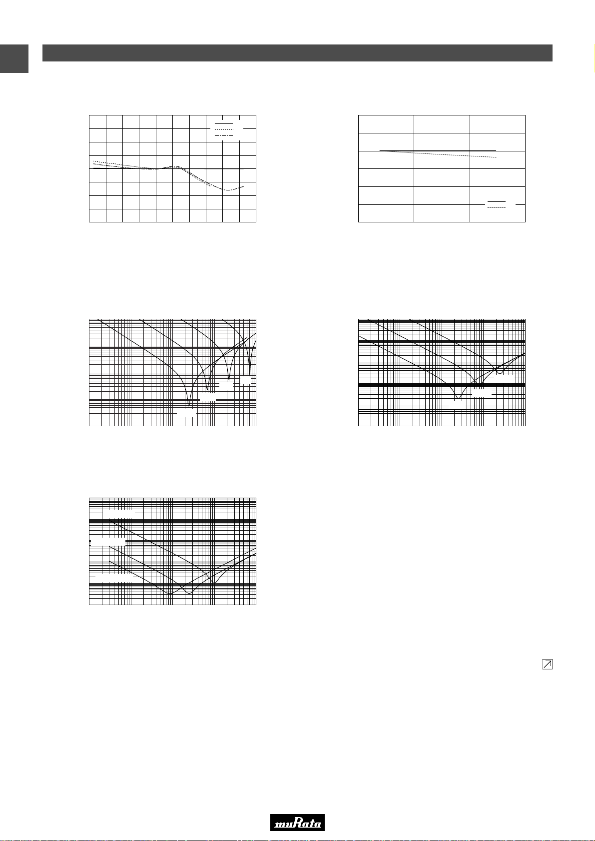
GRM Series Data
Continued on the following page.
■ Capacitance - Temperature Characteristics ■ Capacitance Change - Aging
■ Impedance - Frequency Characteristics
5C: GRM15 R∆: GRM15
R∆
-20
-15
-10
-5
0
5
10
15
20
-60 -40 -20 0 20 40 60 80 100 120 140
5C
R6
R7
Measuring condition: 5C ··· 1MHz, R∆ ··· 1kHz
Temperature (°C)
Capacitance Change (%)
-40
-30
-20
-10
0
10
20
10 100 1000 10000
Measuring condition: 5C ··· 1MHz, R∆ ··· 1kHz
Time (Hr)
Capacitance Change (%)
5C
R∆
0.01
0.1
1
10
100
100001000100101
1000pF
100pF
10pF
1pF
0.001
0.01
0.1
1
10
100
0.1µF
0.01µF
1000pF
10001001010.1
0.001
0.01
0.1
1
10
100
0.01 0.1 1 10 100
GRM15 1µF
GRM18 10µF
GRM31 100µF
Frequency (MHz)Frequency (MHz)
Frequency (MHz)
Impedance (Ω) Impedance (Ω)
Impedance (Ω)
The data herein are given in typical values, not guaranteed ratings.
Please refer to our Web site or contact our sales representatives for individual Part Number's data.
Our Web Site: http://www.murata.com/products/capacitor/tech_data/index.html
• This PDF catalog is downloaded from the website of Murata Manufacturing co., ltd. Therefore, it’s specifications are subject to change or our products in it may be discontinued without advance notice. Please check with our
!Note
1
• Please read rating and !CAUTION (for storage, operating, rating, soldering, mounting and handling) in this catalog to prevent smoking and/or burning, etc.
!Note
sales representatives or product engineers before ordering.
• This catalog has only typical specifications because there is no space for detailed specifications. Therefore, please approve our product specifications or transact the approval sheet for product specifications before ordering.
• This PDF catalog has only typical specifications because there is no space for detailed specifications. Therefore, please approve our product specifications or transact the approval sheet for product specifications before ordering.
GRM Series Data
C02E.pdf
09.9.18
60
Page 63
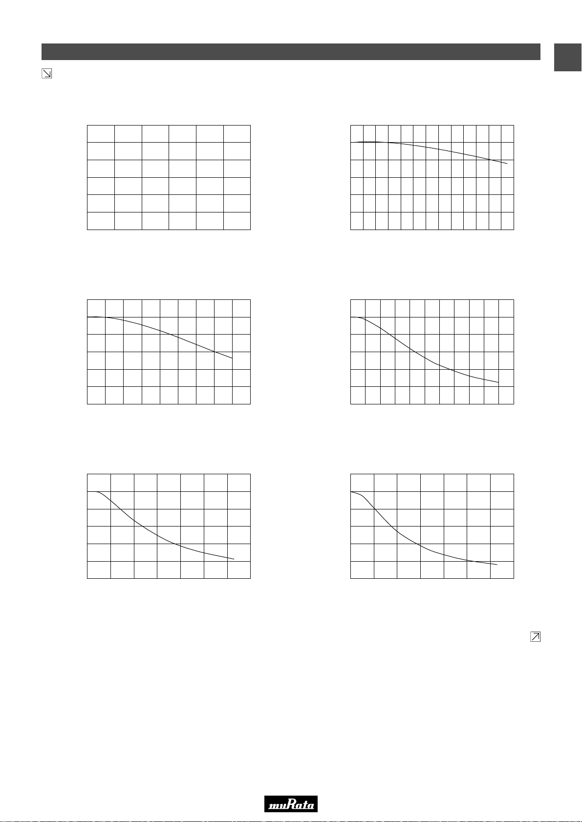
GRM Series Data
Continued from the preceding page.
Continued on the following page.
■ Capacitance - DC Voltage Characteristics
Temperature Compensating Type: GRM1555C1H102JA01 High Dielectric Constant Type: GRM155R71E103KA01
High Dielectric Constant Type: GRM155R71C104KA88
High Dielectric Constant Type: GRM188R60J106ME47 High Dielectric Constant Type: GRM31CR60J107ME39
-100
-80
-60
-40
-20
0
20
0 10 20 30 40 50 60
-100
-80
-60
-40
-20
0
20
0 2 4 6 8 10 12 14 16 18 20 22 24 26
-100
-80
-60
-40
-20
0
20
0 2 4 6 8 10 12 14 16 18
-100
-80
-60
-40
-20
0
20
0 1 2 3 4 5 6 7
-100
-80
-60
-40
-20
0
20
0 1 2 3 4 5 6 7
Measuring condition: 1MHz Measuring condition: 1kHz
Measuring condition: 1kHz
Measuring condition: 1kHz Measuring condition: 120Hz
DC Voltage (VDC) DC Voltage (VDC)
DC Voltage (VDC)
DC Voltage (VDC) DC Voltage (VDC)
Capacitance Change (%)
Capacitance Change (%) Capacitance Change (%)
Capacitance Change (%)
Capacitance Change (%)
The data herein are given in typical values, not guaranteed ratings.
Please refer to our Web site or contact our sales representatives for individual Part Number's data.
Our Web Site: http://www.murata.com/products/capacitor/tech_data/index.html
-100
-80
-60
-40
-20
0
20
43210 5 876 9 10 11
DC Voltage (VDC)
High Dielectric Constant Type: GRM155R61A105KE15
Measuring condition: 1kHz
Capacitance Change (%)
• This PDF catalog is downloaded from the website of Murata Manufacturing co., ltd. Therefore, it’s specifications are subject to change or our products in it may be discontinued without advance notice. Please check with our
!Note
• Please read rating and !CAUTION (for storage, operating, rating, soldering, mounting and handling) in this catalog to prevent smoking and/or burning, etc.
!Note
sales representatives or product engineers before ordering.
• This catalog has only typical specifications because there is no space for detailed specifications. Therefore, please approve our product specifications or transact the approval sheet for product specifications before ordering.
• This PDF catalog has only typical specifications because there is no space for detailed specifications. Therefore, please approve our product specifications or transact the approval sheet for product specifications before ordering.
C02E.pdf
09.9.18
GRM Series Data
1
61
Page 64

GRM Series Data
Continued from the preceding page.
■ Capacitance - AC Voltage Characteristics
Temperature Compensating Type: GRM1555C1H102JA01 High Dielectric Constant Type: GRM155R71E103KA01
High Dielectric Constant Type: GRM155R71C104KA88
High Dielectric Constant Type: GRM188R60J106ME47 High Dielectric Constant Type: GRM31CR60J107ME39
-60
-50
-40
-30
-20
-10
0
10
20
30
0.0 0.5 1.0 1.5 2.0 2.5
-60
-50
-40
-30
-20
-10
0
10
20
30
0.0 0.5 1.0 1.5 2.0 2.5
-60
-50
-40
-30
-20
-10
0
10
20
30
0.0 0.5 1.0 1.5 2.0 2.5
-60
-50
-40
-30
-20
-10
0
10
20
30
0.0 0.5 1.0 1.5 2.0 2.5
-60
-50
-40
-30
-20
-10
0
10
20
30
0.0 0.5 1.0 1.5 2.0 2.5
Measuring condition: 1kHzMeasuring condition: 1MHz
Measuring condition: 1kHz
Measuring condition: 1kHz Measuring condition: 120Hz
AC Voltage (Vr.m.s.) AC Voltage (Vr.m.s.)
AC Voltage (Vr.m.s.)
AC Voltage (Vr.m.s.) AC Voltage (Vr.m.s.)
Capacitance Change (%) Capacitance Change (%)
Capacitance Change (%)
Capacitance Change (%)
Capacitance Change (%)
The data herein are given in typical values, not guaranteed ratings.
Please refer to our Web site or contact our sales representatives for individual Part Number's data.
Our Web Site: http://www.murata.com/products/capacitor/tech_data/index.html
-60
-50
-40
-30
-20
-10
0
10
20
30
AC Voltage (Vr.m.s.)
High Dielectric Constant Type: GRM155R61A105KE15
Measuring condition: 1kHz
Capacitance Change (%)
0.0 0.5 1.0 1.5 2.0 2.5
• This PDF catalog is downloaded from the website of Murata Manufacturing co., ltd. Therefore, it’s specifications are subject to change or our products in it may be discontinued without advance notice. Please check with our
!Note
1
• Please read rating and !CAUTION (for storage, operating, rating, soldering, mounting and handling) in this catalog to prevent smoking and/or burning, etc.
!Note
sales representatives or product engineers before ordering.
• This catalog has only typical specifications because there is no space for detailed specifications. Therefore, please approve our product specifications or transact the approval sheet for product specifications before ordering.
• This PDF catalog has only typical specifications because there is no space for detailed specifications. Therefore, please approve our product specifications or transact the approval sheet for product specifications before ordering.
GRM Series Data
C02E.pdf
09.9.18
62
Page 65
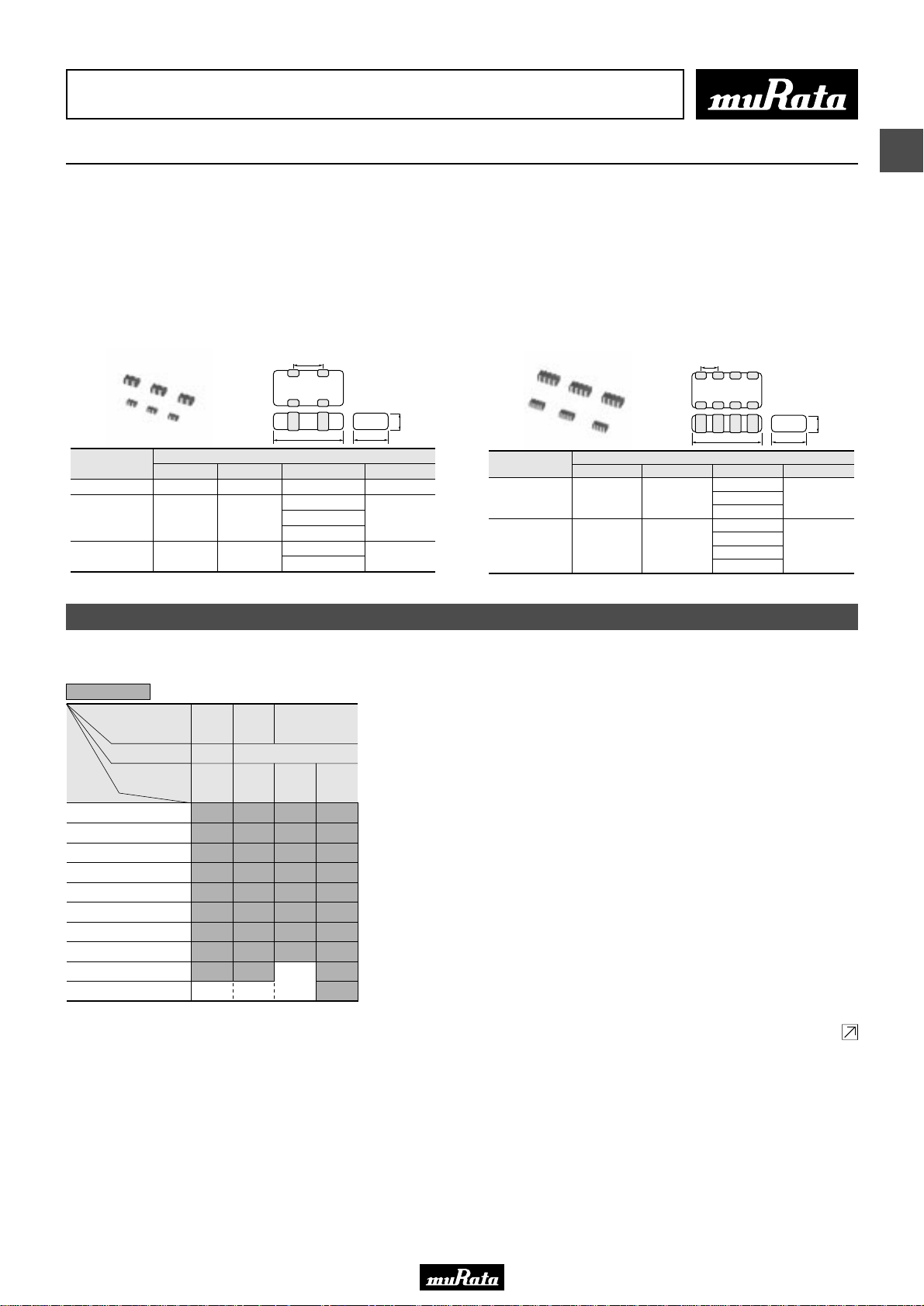
• This PDF catalog is downloaded from the website of Murata Manufacturing co., ltd. Therefore, it’s specifications are subject to change or our products in it may be discontinued without advance notice. Please check with our
!Note
• Please read rating and !CAUTION (for storage, operating, rating, soldering, mounting and handling) in this catalog to prevent smoking and/or burning, etc.
!Note
sales representatives or product engineers before ordering.
• This catalog has only typical specifications because there is no space for detailed specifications. Therefore, please approve our product specifications or transact the approval sheet for product specifications before ordering.
• This PDF catalog has only typical specifications because there is no space for detailed specifications. Therefore, please approve our product specifications or transact the approval sheet for product specifications before ordering.
Chip Monolithic Ceramic Capacitors
C02E.pdf
09.9.18
Capacitor Array GNM Series
■ Features
1. High density mounting due to mounting space saving
2. Mounting cost saving
■ Applications
General electronic equipment
GNM0M2/1M2/212
P
T
W
P
0.45 ±0.05
0.64 ±0.05
1.0 ±0.1
Part Number
GNM0M2
GNM1M2
GNM212
L
0.9 ±0.05
1.37 ±0.15
2.0 ±0.15
L
Dimensions (mm)
W
0.6 ±0.05
1.0 ±0.15 0.6 ±0.1
1.25 ±0.15
T
0.45 ±0.05
0.5 +0.05/-0.10
0.8 +0/-0.15
0.6 ±0.1
0.85 ±0.1
Part Number
GNM214
GNM314
L
2.0 ±0.15
3.2 ±0.15
GNM214/314
P
Dimensions (mm)
W
1.25 ±0.15
1.6 ±0.15
L
T
0.5 +0.05/-0.1
0.6 ±0.1
0.85 ±0.1
0.8 ±0.1
0.85 ±0.1
1.0 ±0.1
1.15 ±0.1
2
T
W
P
0.5 ±0.05
0.8 ±0.1
Capacitance Table
Temperature Compensating Type C0G(5C) Characteristics
0.6
Capacitance
The part number code is shown in ( ) and Unit is shown in [ ]. < >: EIA [inch] Code
ex.0.6: T Dimension [mm]
LxW
[mm]
Number of Elements
Rated Voltage
[Vdc]
10pF(100)
15pF(150)
22pF(220)
33pF(330)
47pF(470)
68pF(680)
100pF(101)
150pF(151)
220pF(221)
330pF(331)
1.37x1.0
2.0x1.25
(1M)
<0504>
(21)
<0805>
2(2) 4(4)
50
50
(1H)
(1H)
0.6
0.6
0.6
0.6
0.6
0.6
0.6
0.6
0.6
0.6
0.6
0.6
0.6
0.6
0.6
0.6
0.6
0.6
3.2x1.6
(31)
<1206>
100
(2A)50(1H)
0.8
0.8
0.8
0.8
0.8
0.8
0.8
0.8
0.8
0.8
0.8
0.8
0.8
0.8
0.8
0.8
0.8
0.8
Continued on the following page.
63
Page 66
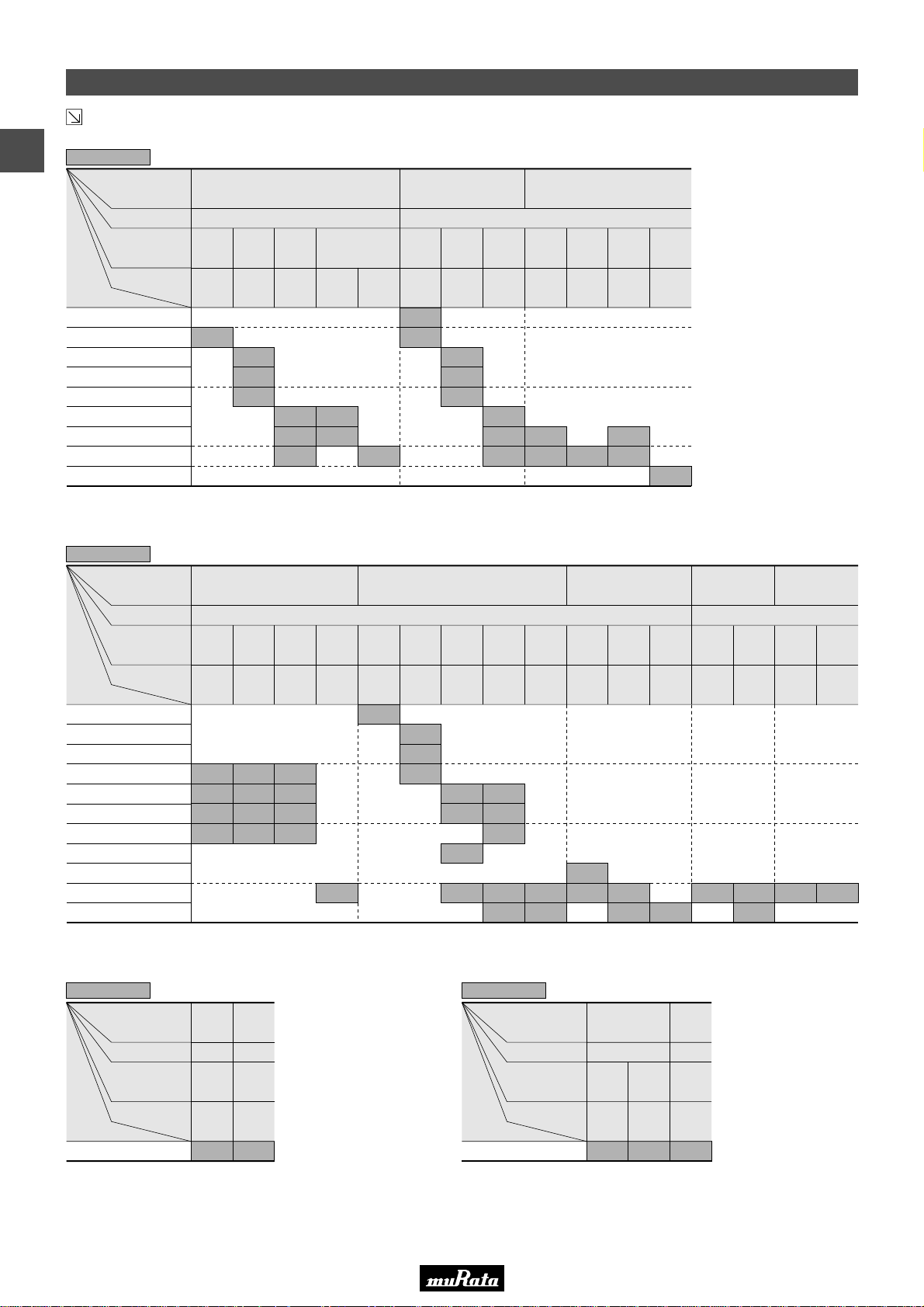
• This PDF catalog is downloaded from the website of Murata Manufacturing co., ltd. Therefore, it’s specifications are subject to change or our products in it may be discontinued without advance notice. Please check with our
!Note
• Please read rating and !CAUTION (for storage, operating, rating, soldering, mounting and handling) in this catalog to prevent smoking and/or burning, etc.
!Note
sales representatives or product engineers before ordering.
• This catalog has only typical specifications because there is no space for detailed specifications. Therefore, please approve our product specifications or transact the approval sheet for product specifications before ordering.
• This PDF catalog has only typical specifications because there is no space for detailed specifications. Therefore, please approve our product specifications or transact the approval sheet for product specifications before ordering.
Capacitance Table
Continued from the preceding page.
2
High Dielectric Constant Type X7R(R7)/X7S(C7) Characteristics
0.6
Capacitance
10000pF(103)
22000pF(223)
47000pF(473)
The part number code is shown in ( ) and Unit is shown in [ ]. < >: EIA [inch] Code
ex.0.6: T Dimension [mm]
LxW
[mm]
Number of Elements
Rated Voltage
[Vdc]
TC
470pF(471)
1000pF(102)
2200pF(222)
4700pF(472)
0.10µF(104)
1.0µF(105)
50
(1H)
X7R
(R7)
0.6
1.37x1.0
(1M)
<0504>
2.0x1.25
(21)
<0805>
2(2) 4(4)
25
(1E)
X7R
(R7)
0.6
0.6
0.6
16
(1C)
X7R
(R7)
0.6
0.6
0.6
X7R
(R7)
0.6
0.6
10
(1A)
X7S
(C7)
0.6
50
(1H)
X7R
(R7)
0.6
0.6
25
(1E)
X7R
(R7)
0.6
0.6
0.6
16
(1C)
X7R
(R7)
0.85
0.85
0.85
50
(1H)
X7R
(R7)
0.85
0.85
3.2x1.6
<1206>
25
(1E)
X7R
(R7)
0.85
(31)
16
(1C)
X7R
(R7)
1.0
1.0
6.3
(0J)
X7R
(R7)
1.15
C02E.pdf
09.9.18
High Dielectric Constant Type X5R(R6) Characteristics
0.6
Capacitance
10000pF(103)
22000pF(223)
47000pF(473)
The part number code is shown in ( ) and Unit is shown in [ ]. < >: EIA [inch] Code
ex.0.6: T Dimension [mm]
LxW
[mm]
Number of Elements
Rated Voltage
[Vdc]
TC
1000pF(102)
2200pF(222)
4700pF(472)
0.10µF(104)
0.22µF(224)
0.47µF(474)
1.0µF(105)
2.2µF(225)
16
(1C)
X5R
(R6)
0.45
0.45
0.45
0.45
0.9x0.6
<0302>
10
(1A)
X5R
(R6)
0.45
0.45
0.45
0.45
(0M)
6.3
(0J)
X5R
(R6)
0.45
0.45
0.45
0.45
4
(0G)50(1H)
X5R
X5R
(R6)
(R6)
0.6
0.45
1.37x1.0
<0504>
2(2) 4(4)
25
(1E)
X5R
(R6)
0.6
0.6
0.6
High Dielectric Constant Type X7R(R7) Characteristics Low Profile
0.5
Capacitance
The part number code is shown in ( ) and Unit is shown in [ ].
< >: EIA [inch] Code
ex.0.5: T Dimension [mm]
LxW
[mm]
Number of Elements
Rated Voltage
[Vdc]
TC
0.10µF(104)
1.37x1.0
2.0x1.25
(1M)
<0504>
<0805>
2(2) 4(4)
16
(1C)
X7R
(R7)
0.5
(21)
16
(1C)
X7R
(R7)
0.5
(1M)
(21)
<0805>
2.0x1.25
16
(1C)10(1A)
X5R
X5R
X5R
(R6)
(R6)
(R6)
0.6
0.6
0.6
0.6
0.6
0.8
0.8
0.8 0.85
0.8
6.3
(0J)
0.8
0.8
16
(1C)
X5R
(R6)
0.85
0.85
10
(1A)
X5R
(R6)
0.85
0.85
(0J)
X5R
(R6)
0.85
2.0x1.25
(21)
<0805>
6.3
10
6.3
(1A)
(0J)
X5R
X5R
(R6)
(R6)
0.85 0.85 0.85
0.85
High Dielectric Constant Type X5R(R6) Characteristics Low Profile
0.5
Capacitance
The part number code is shown in ( ) and Unit is shown in [ ].
< >: EIA [inch] Code
ex.0.5: T Dimension [mm]
LxW
[mm]
Number of Elements
Rated Voltage
[Vdc]
TC
1.0µF(105)
1.37x1.0
(1M)
<0504>
2(2) 4(4)
16
(1C)10(1A)
X5R
X5R
(R6)
(R6)
0.5
0.5 0.5
2.0x1.25
(21)
<0805>
16
(1C)
X5R
(R6)
3.2x1.6
<1206>
16
(1C)
X5R
(R6)
(31)
10
(1A)
X5R
(R6)
64
Page 67
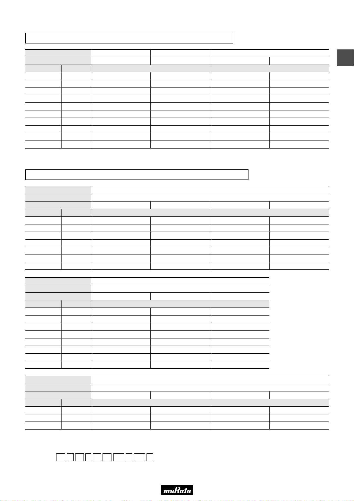
• This PDF catalog is downloaded from the website of Murata Manufacturing co., ltd. Therefore, it’s specifications are subject to change or our products in it may be discontinued without advance notice. Please check with our
!Note
• Please read rating and !CAUTION (for storage, operating, rating, soldering, mounting and handling) in this catalog to prevent smoking and/or burning, etc.
!Note
sales representatives or product engineers before ordering.
• This catalog has only typical specifications because there is no space for detailed specifications. Therefore, please approve our product specifications or transact the approval sheet for product specifications before ordering.
• This PDF catalog has only typical specifications because there is no space for detailed specifications. Therefore, please approve our product specifications or transact the approval sheet for product specifications before ordering.
Temperature Compensating Type C0G(5C) Characteristics
C02E.pdf
09.9.18
LxW [mm]
Rated Volt. [Vdc]
Capacitance Tolerance Part Number
10pF(100)
15pF(150)
22pF(220)
33pF(330)
47pF(470)
68pF(680)
100pF(101)
150pF(151)
220pF(221)
330pF(331)
The part number code is shown in ( ) and Unit is shown in [ ]. < >: EIA [inch] Code
±10%(K)
±10%(K)
±10%(K)
±10%(K)
±10%(K)
±10%(K)
±10%(K)
±10%(K)
±10%(K)
±10%(K)
1.37x1.0(1M)<0504> 2.0x1.25(21)<0805> 3.2x1.6(31)<1206>
50(1H) 50(1H) 100(2A) 50(1H)
GNM1M25C1H100KD01D
GNM1M25C1H150KD01D
GNM1M25C1H220KD01D
GNM1M25C1H330KD01D
GNM1M25C1H470KD01D
GNM1M25C1H680KD01D
GNM1M25C1H101KD01D
GNM1M25C1H151KD01D
GNM1M25C1H221KD01D
GNM2145C1H100KD01D
GNM2145C1H150KD01D
GNM2145C1H220KD01D
GNM2145C1H330KD01D
GNM2145C1H470KD01D
GNM2145C1H680KD01D
GNM2145C1H101KD01D
GNM2145C1H151KD01D
GNM2145C1H221KD01D
GNM3145C2A100KD01D
GNM3145C2A150KD01D
GNM3145C2A220KD01D
GNM3145C2A330KD01D
GNM3145C2A470KD01D
GNM3145C2A680KD01D
GNM3145C2A101KD01D
GNM3145C2A151KD01D
High Dielectric Constant Type X7R(R7)/X7S(C7) Characteristics
LxW [mm]
Number of Elements 2(2)
Rated Volt. [Vdc]
Capacitance Tolerance Part Number
1000pF(102)
2200pF(222)
4700pF(472)
10000pF(103)
22000pF(223)
47000pF(473)
0.10µF(104)
±20%(M)
±20%(M)
±20%(M)
±20%(M)
±20%(M)
±20%(M)
±20%(M)
GNM1M2R71H102MA01D
50(1H)
GNM1M2R71E222MA01D
GNM1M2R71E472MA01D
GNM1M2R71E103MA01D
1.37x1.0(1M)<0504>
25(1E) 16(1C)
GNM1M2R71C223MA01D
GNM1M2R71C473MA01D
GNM1M2R71C104MA01D
2
GNM3145C1H100KD01D
GNM3145C1H150KD01D
GNM3145C1H220KD01D
GNM3145C1H330KD01D
GNM3145C1H470KD01D
GNM3145C1H680KD01D
GNM3145C1H101KD01D
GNM3145C1H151KD01D
GNM3145C1H221KD01D
GNM3145C1H331KD01D
10(1A)
GNM1M2R71A223MA01D
GNM1M2R71A473MA01D
GNM1M2C71A104MA01D
LxW [mm]
Number of Elements 4(4)
Rated Volt. [Vdc]
Capacitance Tolerance Part Number
470pF(471)
1000pF(102)
2200pF(222)
4700pF(472)
10000pF(103)
22000pF(223)
47000pF(473)
0.10µF(104)
LxW [mm]
Number of Elements 4(4)
Rated Volt. [Vdc]
Capacitance Tolerance Part Number
47000pF(473)
0.10µF(104)
1.0µF(105)
The part number code is shown in ( ) and Unit is shown in [ ]. < >: EIA [inch] Code
*: Please refer to GNM series Specifications and Test Method(2).
±20%(M)
±20%(M)
±20%(M)
±20%(M)
±20%(M)
±20%(M)
±20%(M)
±20%(M)
±20%(M)
±20%(M)
±20%(M)
GNM214R71H471MA01D
GNM214R71H102MA01D
GNM314R71H473MA11D
GNM314R71H104MA11D GNM314R71E104MA11D
50(1H)
50(1H)
2.0x1.25(21)<0805>
25(1E) 16(1C)
GNM214R71E222MA01D
GNM214R71E472MA01D
GNM214R71E103MA01D
GNM214R71C223MA01D
GNM214R71C473MA01D
GNM214R71C104MA01D
3.2x1.6(31)<1206>
25(1E) 16(1C) 6.3(0J)
GNM314R71C473MA01L
GNM314R71C104MA01L
GNM314R70J105MA01L
(Part Number)
Packaging Code in Part Number is a code shows STD 180mm Reel Taping.
GN M 1M 2 5C 1H 100 K D01 D
e r t y u i o !0
wq
qProduct ID wSeries eDimension (LxW) rNumber of Elements
tTemperature Characteristics yRated Voltage uCapacitance
iCapacitance Tolerance oIndividual Specification Code !0Packaging
65
Page 68
• This PDF catalog is downloaded from the website of Murata Manufacturing co., ltd. Therefore, it’s specifications are subject to change or our products in it may be discontinued without advance notice. Please check with our
!Note
• Please read rating and !CAUTION (for storage, operating, rating, soldering, mounting and handling) in this catalog to prevent smoking and/or burning, etc.
!Note
sales representatives or product engineers before ordering.
• This catalog has only typical specifications because there is no space for detailed specifications. Therefore, please approve our product specifications or transact the approval sheet for product specifications before ordering.
• This PDF catalog has only typical specifications because there is no space for detailed specifications. Therefore, please approve our product specifications or transact the approval sheet for product specifications before ordering.
High Dielectric Constant Type X5R(R6) Characteristics
C02E.pdf
09.9.18
2
LxW [mm]
Number of Elements
Rated Volt. [Vdc]
Capacitance Tolerance Part Number
10000pF(103)
22000pF(223)
47000pF(473)
0.10µF(104)
1.0µF(105)
LxW [mm]
Number of Elements
Rated Volt. [Vdc]
Capacitance Tolerance Part Number
1000pF(102)
2200pF(222)
4700pF(472)
10000pF(103)
22000pF(223)
47000pF(473)
0.22µF(224)
1.0µF(105)
±20%(M)
±20%(M)
±20%(M)
±20%(M)
±20%(M)
±20%(M)
±20%(M)
±20%(M)
±20%(M)
±20%(M)
±20%(M)
±20%(M)
±20%(M)
GNM0M2R61C103ME18D*
GNM0M2R61C223ME18D*
GNM0M2R61C473ME18D*
GNM0M2R61C104ME18D*
GNM1M2R61H102MA01D
16(1C) 10(1A) 6.3(0J) 4(0G)
GNM0M2R61A103ME17D*
GNM0M2R61A223ME17D*
GNM0M2R61A473ME17D*
GNM0M2R61A104ME17D*
1.37x1.0(1M)<0504>
50(1H) 25(1E) 16(1C)
GNM1M2R61E222MA01D
GNM1M2R61E472MA01D
GNM1M2R61E103MA01D
0.9x0.6(0M)<0302>
2(2)
GNM0M2R60J103ME17D*
GNM0M2R60J223ME17D*
GNM0M2R60J473ME17D*
GNM0M2R60J104ME17D*
GNM0M2R60G105ME17D*
2(2)
GNM1M2R61C223MA01D
GNM1M2R61C473MA01D
GNM1M2R61C224ME18D*
GNM1M2R61C105ME18D*
LxW [mm]
Number of Elements
Rated Volt. [Vdc]
Capacitance Tolerance Part Number
22000pF(223)
47000pF(473)
0.10µF(104)
1.0µF(105)
2.2µF(225)
LxW [mm]
Number of Elements
Rated Volt. [Vdc]
Capacitance Tolerance Part Number
0.47µF(474)
1.0µF(105)
2.2µF(225)
The part number code is shown in ( ) and Unit is shown in [ ]. < >: EIA [inch] Code
*: Please refer to GNM series Specifications and Test Method(2).
±20%(M)
±20%(M)
±20%(M)
±20%(M)
±20%(M)
±20%(M)
±20%(M)
±20%(M)
GNM1M2R61A223MA01D
GNM1M2R61A473MA01D
GNM1M2R61A104MA01D
GNM1M2R61A105ME17D*
GNM1M2R61A225ME18D*
GNM212R61C474MA16D
GNM212R61C105MA16D GNM212R61A105MA13D
1.37x1.0(1M)<0504>
2(2)
10(1A) 6.3(0J)
GNM1M2R60J105ME12D*
GNM1M2R60J225ME18D*
2.0x1.25(21)<0805>
2(2)
16(1C) 10(1A) 6.3(0J)
GNM212R61A225ME16D* GNM212R60J225ME16D*
(Part Number)
Packaging Code in Part Number is a code shows STD Tray.
GN M 0M 2 R6 1C 103 M E18 D
e r t y u i o !0
wq
66
qProduct ID wSeries eDimension (LxW) rNumber of Elements
tTemperature Characteristics yRated Voltage uCapacitance
iCapacitance Tolerance oIndividual Specification Code !0Packaging
Page 69
• This PDF catalog is downloaded from the website of Murata Manufacturing co., ltd. Therefore, it’s specifications are subject to change or our products in it may be discontinued without advance notice. Please check with our
!Note
• Please read rating and !CAUTION (for storage, operating, rating, soldering, mounting and handling) in this catalog to prevent smoking and/or burning, etc.
!Note
sales representatives or product engineers before ordering.
• This catalog has only typical specifications because there is no space for detailed specifications. Therefore, please approve our product specifications or transact the approval sheet for product specifications before ordering.
• This PDF catalog has only typical specifications because there is no space for detailed specifications. Therefore, please approve our product specifications or transact the approval sheet for product specifications before ordering.
High Dielectric Constant Type X5R(R6) Characteristics
C02E.pdf
09.9.18
LxW [mm]
Number of Elements
Rated Volt. [Vdc]
Capacitance Tolerance Part Number
1.0µF(105)
2.2µF(225)
LxW [mm]
Number of Elements
Rated Volt. [Vdc]
Capacitance Tolerance Part Number
1.0µF(105) ±20%(M)
The part number code is shown in ( ) and Unit is shown in [ ]. < >: EIA [inch] Code
*: Please refer to GNM series Specifications and Test Method(2).
±20%(M)
±20%(M)
GNM214R61A105ME17D* GNM214R60J105ME17D*
GNM314R61C105MA15D
2.0x1.25(21)<0805>
4(4)
10(1A) 6.3(0J)
GNM214R60J225ME18D*
3.2x1.6(31)<1206>
4(4)
16(1C) 10(1A)
GNM314R61A105MA13D
High Dielectric Constant Type X7R(R7) Characteristics Low Profile
LxW [mm]
Number of Elements
Rated Volt. [Vdc]
Capacitance Tolerance Part Number
0.10µF(104) ±20%(M)
1.37x1.0(1M)<0504>
2(2)
2.0x1.25(21)<0805>
4(4)
16(1C) 16(1C)
GNM1M2R71C104MAA1D GNM214R71C104MAA1D
2
High Dielectric Constant Type X5R(R6) Characteristics Low Profile
LxW [mm]
Number of Elements
Rated Volt. [Vdc]
Capacitance Tolerance Part Number
1.0µF(105) ±20%(M)
The part number code is shown in ( ) and Unit is shown in [ ]. < >: EIA [inch] Code
*: Please refer to GNM series Specifications and Test Method(2).
GNM1M2R61C105MEA2D* GNM1M2R61A105MEA4D*
1.37x1.0(1M)<0504>
2(2)
16(1C) 10(1A)
67
Page 70
In case Non "*" is added in PNs table, please refer to GNM Series Specifications and Test Methods (1).
In case "*" is added in PNs table, please refer to GNM Series Specifications and Test Methods (2).
Continued on the following page.
GNM Series Specifications and Test Methods (1)
Solder the capacitor to the test jig (glass epoxy board) shown in
Fig.1 using a eutectic solder. Then apply 5N force in parallel with
the test jig for 10±1 sec.
The soldering should be done either with an iron or using the
reflow method and should be conducted with care so that the
soldering is uniform and free of defects such as heat shock.
(in mm)
Fig. 1
10
Adhesive Strength
of Termination
No removal of the terminations or other defect should occur.
GNMpp4 GNMpp2
The capacitance change should be measured after 5 min. at
each specified temperature stage.
(1) Temperature Compensating Type
The temperature coefficient is determined using the capacitance measured in step 3 as a reference. When cycling the
temperature sequentially from step1 through 5, the capacitance
should be within the specified tolerance for the temperature
coefficient and capacitance change as Table A.
The capacitance drift is calculated by dividing the differences
between the maximum and minimum measured values in the
steps 1, 3 and 5 by the cap. value in step 3.
(2) High Dielectric Constant Type
The ranges of capacitance change compared with the above
25°C value over the temperature ranges shown in the table
should be within the specified ranges.
9
Capacitance
Temperature
Characteristics
Capacitance
Change
Within the
specified tolerance
(Table A)
Temperature
Coefficient
Within the
specified tolerance
(Table A)
Capacitance
Drift
Within ±0.2%
or ±0.05pF
(Whichever is
larger.)
8Q/Dissipation Factor
(D.F.)
30pF min.: QU1000
30pF max.:
QU400+20C
C: Nominal
Capacitance (pF)
The capacitance/Q/D.F. should be measured at 25°C at the
frequency and voltage shown in the table.
7 Capacitance Within the specified tolerance
The insulation resistance should be measured with a DC
voltage not exceeding the rated voltage at 25°C and 75%RH
max. and within 2 minutes of charging.
6
Insulation
Resistance
More than 10,000MΩ or 500Ω · F
(Whichever is smaller)
No failure should be observed when 300% of the rated voltage
(5C) or 250% of the rated voltage (R7) is applied between the
terminations for 1 to 5 seconds, provided the charge/discharge
current is less than 50mA.
5 Dielectric Strength No defects or abnormalities
Using calipers4 Dimensions Within the specified dimensions
Visual inspection3 Appearance No defects or abnormalities
The rated voltage is defined as the maximum voltage which
may be applied continuously to the capacitor.
When AC voltage is superimposed on DC voltage, V
P-P
or V
O-P
,
whichever is larger, should be maintained within the rated
voltage range.
2 Rated Voltage See the previous pages.
1
Operating
Temperature
Range
5C: –55 to +125°C
R7, C7: –55 to +125°C
R6: –55 to +85°C
No. Test Method
Specifications
Temperature
Compensating Type
High Dielectric Type
Item
Step Temperature (°C)
25±2
–55±3 (for 5C/R7/C7), –30±3 (for F5)
25±2
125±3 (for 5C/R7/C7), 85±3 (for F5)
25±2
1
2
3
4
5
Char.
Item
5C
1±0.1MHz
0.5 to 5Vrms
R7
1±0.1kHz
1.0±0.2Vrms
Frequency
Voltage
Char.
25V min.
0.025
max.
16V
0.035
max.
10V
0.035
max.
6.3V
0.05
max.
R7, R6,
C7
Char.
Temp.
Range
–55°C
to +125°C
Reference
Temp.
25°C
Cap.
Change
Within
±15%
R7
–55°C
to +85°C
Within
±22%
R6
–55°C
to +125°C
C7
Type a
0.5
0.6
0.6
0.8
b
1.6
1.8
2.0
2.5
c
0.32
0.5
0.25
0.4
d
0.32
0.5
0.25
0.4
GNM1M2
GNM212
GNM214
GNM314
Solder resist
Copper foil
c
d
b b
a
a
c
d
Solder resist
Copper foil
• Initial measurement for high dielectric constant type.
Perform a heat treatment at 150+0/-10°C for one hour and
then set for 24±2 hours at room temperature.
Perform the initial measurement.
• This PDF catalog is downloaded from the website of Murata Manufacturing co., ltd. Therefore, it’s specifications are subject to change or our products in it may be discontinued without advance notice. Please check with our
!Note
• Please read rating and !CAUTION (for storage, operating, rating, soldering, mounting and handling) in this catalog to prevent smoking and/or burning, etc.
!Note
sales representatives or product engineers before ordering.
• This catalog has only typical specifications because there is no space for detailed specifications. Therefore, please approve our product specifications or transact the approval sheet for product specifications before ordering.
• This PDF catalog has only typical specifications because there is no space for detailed specifications. Therefore, please approve our product specifications or transact the approval sheet for product specifications before ordering.
GNM Series Specifications and Test Methods (1)
2
C02E.pdf
09.9.18
68
Page 71
In case Non "*" is added in PNs table, please refer to GNM Series Specifications and Test Methods (1).
In case "*" is added in PNs table, please refer to GNM Series Specifications and Test Methods (2).
Continued from the preceding page.
Continued on the following page.
Preheat the capacitor at 120 to 150°C for 1 minute. Immerse
the capacitor in a eutectic solder or Sn-3.0Ag-0.5Cu solder
solution at 270±5°C for 10±0.5 seconds. Let sit at room
temperature for 24±2 hours, then measure.
• Initial measurement for high dielectric constant type
Perform a heat treatment at 150+0/-10°C for one hour and
then let sit for 24±2 hours at room temperature.
Perform the initial measurement.
14
Resistance to
Soldering Heat
The measured and observed characteristics should satisfy the
specifications in the following table.
Appearance
No marking defects
Capacitance
Change
Within ±2.5%
or ±0.25pF
(Whichever is
larger)
R7, R6, C7: Within ±7.5%
Q/D.F.
30pF min.: QU1000
30pF max.:
QU400+20C
C: Nominal
Capacitance (pF)
I.R. More than 10,000MΩ or 500Ω · F (Whichever is smaller)
Dielectric
Strength
No failure
Immerse the capacitor in a solution of ethanol (JIS-K-8101) and
rosin (JIS-K-5902) (25% rosin in weight proportion). Preheat at
80 to 120°C for 10 to 30 seconds. After preheating, immerse in
eutectic solder solution for 2±0.5 seconds at 230±5°C or
Sn-3.0Ag-0.5Cu solder solution for 2±0.5 seconds at 245±5°C.
13
Solderability of
Termination
75% of the terminations are to be soldered evenly and
continuously.
GNM Series Specifications and Test Methods (1)
Char.
25V min.
0.025
max.
16V
0.035
max.
10V
0.035
max.
6.3V
0.05
max.
R7, R6,
C7
Char.
25V min.
0.025
max.
16V
0.035
max.
10V
0.035
max.
6.3V
0.05
max.
R7, R6,
C7
Type a
2.0±0.05
2.0±0.05
2.0±0.05
2.5±0.05
b
0.5±0.05
0.6±0.05
0.7±0.05
0.8±0.05
c
0.32±0.05
0.5±0.05
0.3±0.05
0.4±0.05
d
0.32±0.05
0.5±0.05
0.2±0.05
0.4±0.05
GNM1M2
GNM212
GNM214
GNM314
Solder the capacitor on the test jig (glass epoxy board) shown
in Fig. 2 using a eutectic solder.
Then apply a force in the direction shown in Fig. 3 for 5±1 sec.
The soldering should be done by the reflow method and should
be conducted with care so that the soldering is uniform and free
of defects such as heat shock.
Fig. 3
12 Deflection
Appearance
No marking defects
Capacitance
Change
Within ±5% or ±0.5pF
(Whichever is larger)
Within ±10%
(in mm)
Fig. 2
•GNMpp4 •GNMpp2
Solder the capacitor to the test jig (glass epoxy board) in the
same manner and under the same conditions as (10). The
capacitor should be subjected to a simple harmonic motion
having a total amplitude of 1.5mm, the frequency being varied
uniformly between the approximate limits of 10 and 55Hz. The
frequency range, from 10 to 55Hz and return to 10Hz, should
be traversed in approximately 1 minute. This motion should be
applied for a period of 2 hours in each of 3 mutually perpendicular directions (total of 6 hours).
11
Vibration
Resistance
Appearance
No defects or abnormalities
Capacitance
Within the specified tolerance
Q/D.F.
30pF min.: QU1000
30pF max.:
QU400+20C
C: Nominal
Capacitance (pF)
No. Test Method
Specifications
Temperature
Compensating Type
High Dielectric Type
Item
100
1.0
5.0
b
a
40
c
d
100
1.0
t=0.8mm
5.0
b
a
40
c
d
Capacitance meter
Flexure : V1
20
50
R230
Pressurizing
speed : 1.0mm/sec.
Pressurize
45 45
• This PDF catalog is downloaded from the website of Murata Manufacturing co., ltd. Therefore, it’s specifications are subject to change or our products in it may be discontinued without advance notice. Please check with our
!Note
• Please read rating and !CAUTION (for storage, operating, rating, soldering, mounting and handling) in this catalog to prevent smoking and/or burning, etc.
!Note
sales representatives or product engineers before ordering.
• This catalog has only typical specifications because there is no space for detailed specifications. Therefore, please approve our product specifications or transact the approval sheet for product specifications before ordering.
• This PDF catalog has only typical specifications because there is no space for detailed specifications. Therefore, please approve our product specifications or transact the approval sheet for product specifications before ordering.
C02E.pdf
09.9.18
GNM Series Specifications and Test Methods (1)
2
69
Page 72

In case Non "*" is added in PNs table, please refer to GNM Series Specifications and Test Methods (1).
In case "*" is added in PNs table, please refer to GNM Series Specifications and Test Methods (2).
Continued from the preceding page.
Continued on the following page.
Apply the rated voltage at 40±2°C and 90 to 95% humidity for
500±12 hours.
Remove and let sit for 24±2 hours at room temperature, then
measure.
The charge/discharge current is less than 50mA.
17
Humidity Load
The measured and observed characteristics should satisfy the
specifications in the following table.
Appearance
No marking defects
Capacitance
Change
Within ±7.5%
or ±0.75pF
(Whichever is
larger)
R7, R6, C7: Within ±12.5%
Q/D.F.
30pF and over:
QU200
30pF and below:
QU100+10C/3
C: Nominal
Capacitance (pF)
I.R. More than 500MΩ or 25Ω · F (Whichever is smaller)
Sit the capacitor at 40±2°C and 90 to 95% humidity for 500±12
hours.
Remove and let sit for 24±2 hours at room temperature, then
measure.
16
Humidity Steady
State
The measured and observed characteristics should satisfy the
specifications in the following table.
Appearance
No marking defects
Capacitance
Change
Within ±5%
or ±0.5pF
(Whichever is
larger)
R7, R6, C7: Within ±12.5%
Q/D.F.
30pF and over:
QU350
10pF and over,
30pF and below:
QU275+5C/2
10pF and below:
QU200+10C
C: Nominal
Capacitance (pF)
I.R. More than 1,000MΩ or 50Ω · F (Whichever is smaller)
Fix the capacitor to the supporting jig in the same manner and
under the same conditions as (10). Perform the five cycles
according to the four heat treatments listed in the following
table. Let sit for 24±2 hours (temperature compensating type)
or 48±4 hours (high dielectric constant type) at room
temperature, then measure.
• Initial measurement for high dielectric constant type
Perform a heat treatment at 150+0/-10°C for one hour and
then let sit for 24±2 hours at room temperature.
Perform the initial measurement.
15
Temperature
Cycle
The measured and observed characteristics should satisfy the
specifications in the following table.
Appearance
No marking defects
Capacitance
Change
Within ±2.5%
or ±0.25pF
(Whichever is
larger)
R7, R6, C7: Within ±7.5%
Q/D.F.
30pF min.: QU1000
30pF max.:
QU400+20C
C:Nominal
Capacitance (pF)
I.R. More than 10,000MΩ or 500Ω · F (Whichever is smaller)
Dielectric
Strength
No failure
GNM Series Specifications and Test Methods (1)
Step
Temp. (°C)
Time (min.)
1
Min.
Operating
Temp.+0/–3
30±3
2
Room
Temp.
2 to 3
3
Max.
Operating
Temp. +3/–0
30±3
4
Room
Temp.
2 to 3
Char.
25V min.
0.025
max.
16V
0.035
max.
10V
0.035
max.
6.3V
0.05
max.
R7, R6,
C7
Char. 25V min.
0.05
max.
16V
0.05
max.
10V/6.3V
0.05
max.
R7, R6,
C7
Char. 25V min.
0.05
max.
16V
0.05
max.
10V/6.3V
0.05
max.
R7, R6,
C7
No. Test Method
Specifications
Temperature
Compensating Type
High Dielectric Type
Item
• This PDF catalog is downloaded from the website of Murata Manufacturing co., ltd. Therefore, it’s specifications are subject to change or our products in it may be discontinued without advance notice. Please check with our
!Note
2
• Please read rating and !CAUTION (for storage, operating, rating, soldering, mounting and handling) in this catalog to prevent smoking and/or burning, etc.
!Note
sales representatives or product engineers before ordering.
• This catalog has only typical specifications because there is no space for detailed specifications. Therefore, please approve our product specifications or transact the approval sheet for product specifications before ordering.
• This PDF catalog has only typical specifications because there is no space for detailed specifications. Therefore, please approve our product specifications or transact the approval sheet for product specifications before ordering.
GNM Series Specifications and Test Methods (1)
C02E.pdf
09.9.18
70
Page 73

In case Non "*" is added in PNs table, please refer to GNM Series Specifications and Test Methods (1).
In case "*" is added in PNs table, please refer to GNM Series Specifications and Test Methods (2).
Continued from the preceding page.
Apply 200% of the rated voltage for 1000±12 hours at the
maximum operating temperature ±3°C. Let sit for 24±2 hours
at room temperature, then measure.
The charge/discharge current is less than 50mA.
• Initial measurement for high dielectric constant type.
Apply 200% of the rated DC voltage for one hour at the
maximum operating temperature ±3°C. Remove and let sit for
24±2 hours at room temperature. Perform initial
measurement.
18
High Temperature
Load
The measured and observed characteristics should satisfy the
specifications in the following table.
Appearance
No marking defects
Capacitance
Change
Within ±3%
or ±0.3pF
(Whichever is
larger)
R7, R6, C7: Within ±12.5%
Q/D.F.
30pF and over:
QU350
10pF and over,
30pF and below:
QU275+5C/2
10pF and below:
QU200+10C
C: Nominal
Capacitance (pF)
I.R. More than 1,000MΩ or 50Ω · F (Whichever is smaller)
No. Test Method
Specifications
Temperature
Compensating Type
High Dielectric Type
Item
Char.
Nominal Values
(ppm/°C) Note 1
0±305C
Max.
0.58
Min.
–0.24
Max.
0.40
Min.
–0.17
Max.
–55°C
Capacitance Change from 25°C (%)
–30°C –10°C
0.25
Min.
–0.11
Note 1: Nominal values denote the temperature coefficient within a range of 25 to 125°C.
Table A
GNM Series Specifications and Test Methods (1)
Char. 25V min.
0.04
max.
16V
0.05
max.
10V/6.3V
0.05
max.
R7, R6,
C7
• This PDF catalog is downloaded from the website of Murata Manufacturing co., ltd. Therefore, it’s specifications are subject to change or our products in it may be discontinued without advance notice. Please check with our
!Note
• Please read rating and !CAUTION (for storage, operating, rating, soldering, mounting and handling) in this catalog to prevent smoking and/or burning, etc.
!Note
sales representatives or product engineers before ordering.
• This catalog has only typical specifications because there is no space for detailed specifications. Therefore, please approve our product specifications or transact the approval sheet for product specifications before ordering.
• This PDF catalog has only typical specifications because there is no space for detailed specifications. Therefore, please approve our product specifications or transact the approval sheet for product specifications before ordering.
C02E.pdf
09.9.18
GNM Series Specifications and Test Methods (1)
2
71
Page 74
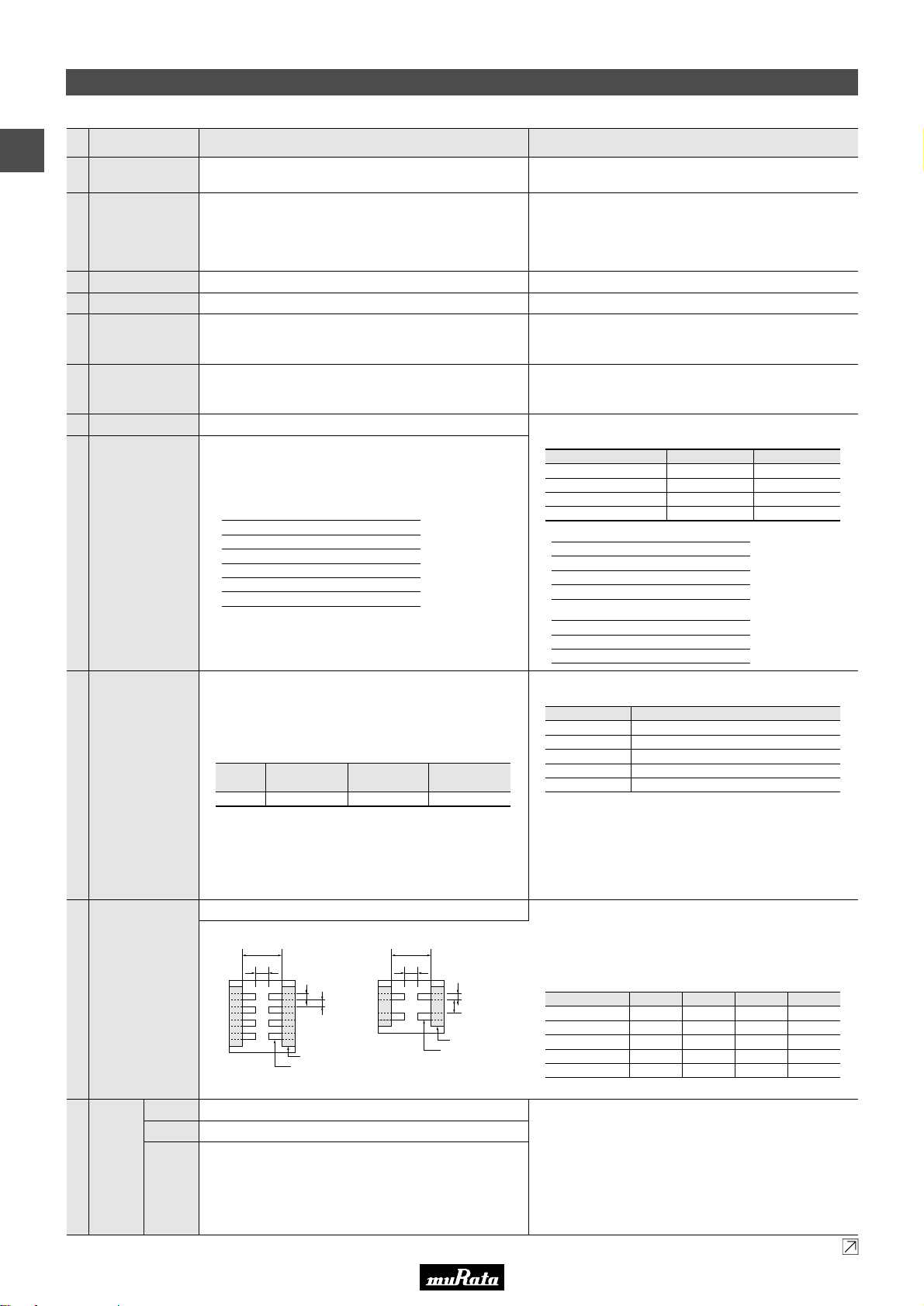
In case Non "*" is added in PNs table, please refer to GNM Series Specifications and Test Methods (1).
In case "*" is added in PNs table, please refer to GNM Series Specifications and Test Methods (2).
Solder the capacitor to the test jig (glass epoxy board) in
the same manner and under the same conditions as (10).
The capacitor should be subjected to a simple harmonic motion
having a total amplitude of 1.5mm, the frequency being varied
uniformly between the approximate limits of 10 and 55Hz.
The frequency range, from 10 to 55Hz and return to 10Hz,
should be traversed in approximately 1 minute. This motion
should be applied for a period of 2 hours in each of 3 mutually
perpendicular directions (total of 6 hours).
11
Vibration
Appearance
No defects or abnormalities
Capacitance
Within the specified tolerance
D.F.
0.1 max.*
3
*3 However 0.125 max. about Table 3 items.
Continued on the following page.
Temperature (°C)Step
25±2
–55±3
25±2
85±3
25±2
1
2
3
4
5
Temp. RangeChar.
–55 to +85°C
Reference
Temp.
25°C
Cap. Change
Within ±15%R6
aType
0.2
0.5
0.6
0.6
0.8
b
0.96
1.6
1.8
2.0
2.5
c
0.25
0.32
0.5
0.25
0.4
d
0.2
0.32
0.5
0.25
0.4
GNM0M2
GNM1M2
GNM212
GNM214
GNM314
Solder the capacitor to the test jig (glass epoxy board) shown in
Fig. 1 using a eutectic solder.
Then apply 5N (GNM0M2: 2N) force in parallel with the test jig for
10±1 sec. The soldering should be done either with an iron or
using the reflow method and should be conducted with care so that
the soldering is uniform and free of defects such as heat shock.
(in mm)
10
Adhesive Strength
of Termination
No removal of the terminations or other defects should occur.
The capacitance change should be measured after 5 min.at
each specified temperature stage.
The ranges of capacitance change compared with the 25°C
value over the temperature ranges shown in the table should be
within the specified ranges.
• Initial measurement for high dielectric constant type.
Perform a heat treatment at 150+0/-10°C for one hour and
then set for 24±2 hours at room temperature.
Perform the initial measurement.
9
Capacitance
Temperature
Characteristics
8
Dissipation Factor
(D.F.)
0.1 max.*
3
Table 3
*3 However 0.125 max. about Table 3 items.
The capacitance/D.F. should be measured at 25°C at the
frequency and voltage shown in the table.
Table 1
Table 2
7 Capacitance Within the specified tolerance
The insulation resistance should be measured with a DC
voltage not exceeding the rated voltage at 25°C and 75%RH
max. and within 1 minute of charging.
6
Insulation Resistance
50Ω · F min.
No failure should be observed when 250% of the rated voltage
is applied between the terminations for 1 to 5 seconds,
provided the charge/discharge current is less than 50mA.
5 Dielectric Strength No defects or abnormalities
Using calipers4 Dimensions Within the specified dimension
Visual inspection3 Appearance No defects or abnormalities
The rated voltage is defined as the maximum voltage which
may be applied continuously to the capacitor.
When AC voltage is superimposed on DC voltage, V
P-P
or V
O-P
,
whichever is larger, should be maintained within the rated
voltage range.
2 Rated Voltage See the previous pages.
1
Operating
Temperature Range
R6: –55°C to +85°C
Measuring Frequency
Nominal Capacitance
1±0.1kHz
1±0.1kHz
1±0.1kHz
1±0.1kHz
Measuring Voltage
1.0±0.2Vrms
0.5±0.1Vrms
0.5±0.1Vrms
1.0±0.1Vrms
CV10µF *1 (10V min.)
CV10µF *
2
(6.3V max.)
*
1
For items in Table1
*
2
For items in Table2
GNM Series Specifications and Test Methods (2)
a
Solder resist
Copper foil
c
d
b b
a
c
d
Solder resist
Copper foil
No. Test MethodSpecificationsItem
Fig. 1
GNMpp4 GNMpp2
GNM0M2 R6 1A 104
GNM0M2 R6 1C 104
GNM1M2 R6 1A 105/225
GNM1M2 R6 1C 224/105
GNM0M2 R6 0J 103/223/473
GNM212 R6 0J 225
GNM214 R6 0J 105
GNM0M2 R6 103/223/473/104
GNM1M2 R6 0J 105/225
GNM1M2 R6 1A 225
GNM212 R6 0J 225
GNM212 R6 1A 225
GNM214 R6 0J 225
• This PDF catalog is downloaded from the website of Murata Manufacturing co., ltd. Therefore, it’s specifications are subject to change or our products in it may be discontinued without advance notice. Please check with our
!Note
• Please read rating and !CAUTION (for storage, operating, rating, soldering, mounting and handling) in this catalog to prevent smoking and/or burning, etc.
!Note
sales representatives or product engineers before ordering.
• This catalog has only typical specifications because there is no space for detailed specifications. Therefore, please approve our product specifications or transact the approval sheet for product specifications before ordering.
• This PDF catalog has only typical specifications because there is no space for detailed specifications. Therefore, please approve our product specifications or transact the approval sheet for product specifications before ordering.
GNM Series Specifications and Test Methods (2)
2
72
C02E.pdf
09.9.18
Page 75
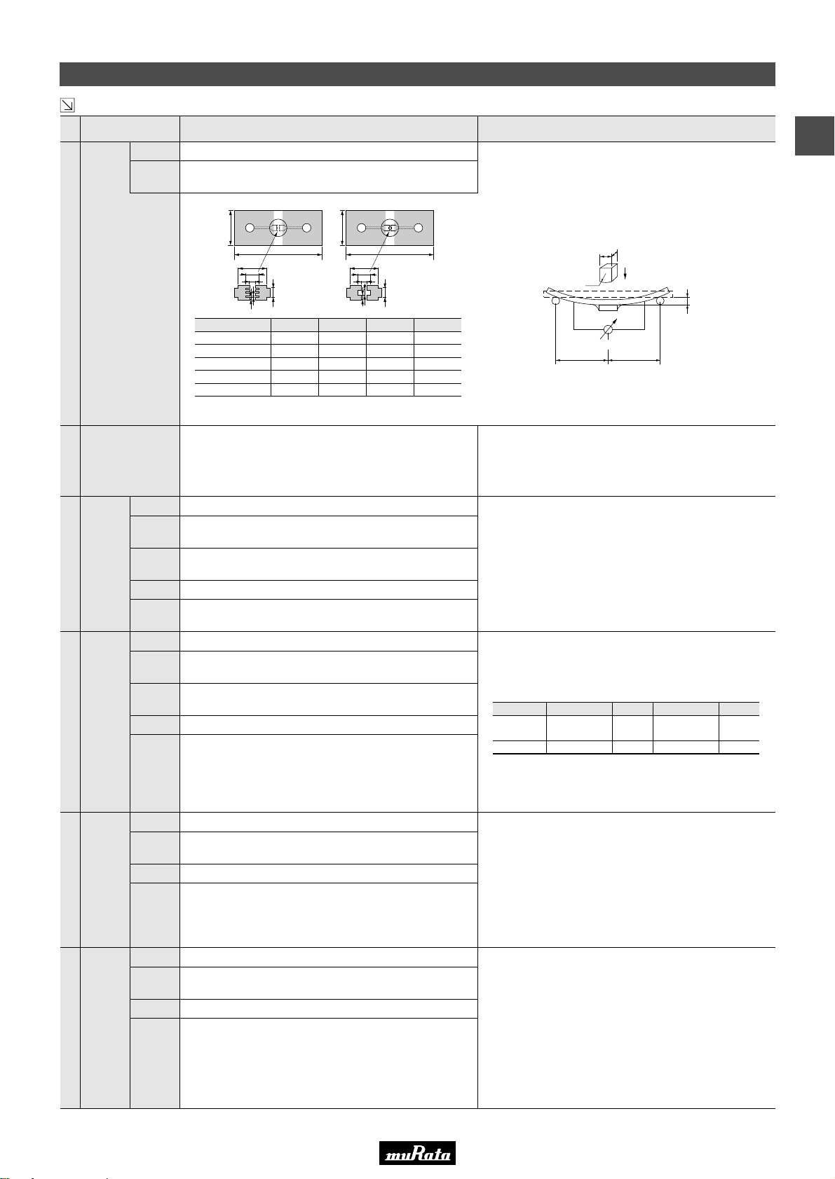
In case Non "*" is added in PNs table, please refer to GNM Series Specifications and Test Methods (1).
In case "*" is added in PNs table, please refer to GNM Series Specifications and Test Methods (2).
Continued from the preceding page.
GNM Series Specifications and Test Methods (2)
100
1.0
5.0
b
a
40
c
d
100
1.0
5.0
b
a
40
c
d
Capacitance meter
Flexure : V1
20
50
R230
Pressurizing
speed : 1.0mm/sec.
Pressurize
45 45
Apply 150% (GNM1M2R61A225/1C105: 125% of the rated
voltage) of the rated voltage for 1000±12 hours at the
maximum operating temperature ±3°C. Let sit for 24±2 hours
at room temperature, then measure.
The charge/discharge current is less than 50mA.
• Initial measurement
Perform a heat treatment at 150 +0/-10°C for one hour
and then let sit for 24±2 hours at room temperature.
Perform the initial measurement.
• Measurement after test
Perform a heat treatment at 150 +0/-10°C for one hour and
then let sit for 24±2 hours at room temperature, then measure.
17
Durability
Appearance
No marking defects
Capacitance
Change
R6: Within ±12.5%
D.F. 0.2 max.
I.R. 25Ω · F min.
Apply the rated voltage at 40±2°C and 90 to 95% humidity for
500±12 hours. The charge/discharge current is less than 50mA.
• Initial measurement
Perform a heat treatment at 150 +0/-10°C for one hour
and then let sit for 24±2 hours at room temperature.
Perform the initial measurement.
• Measurement after test
Perform a heat treatment at 150 +0/-10°C for one hour
and then let sit for 24±2 hours at room temperature, then
measure.
16
High
Temperature
High
Humidity
(Steady)
Appearance
No marking defects
Capacitance
Change
R6: Within ±12.5%
D.F. 0.2 max.
I.R. 12.5Ω · F min.
Fix the capacitor to the supporting jig in the same manner and
under the same conditions as (10).
Perform the five cycles according to the four heat treatments
listed in the following table.
Let sit for 24±2 hours at room temperature, then measure.
• Initial measurement
Perform a heat treatment at 150 +0/-10 °C for one hour and
then let sit for 24±2 hours at room temperature.
Perform the initial measurement.
15
Temperature
Cycle
Appearance
No marking defects
Capacitance
Change
R6*5: Within ±12.5%
*
5
GNM0M2R60E105: Within ±15%
D.F.
0.1 max. *
3
*3 However 0.125 max. about Table 3 items.
I.R. 50Ω · F min.
Dielectric
Strength
No failure
Preheat the capacitor at 120 to 150°C for 1 minute. Immerse
the capacitor in a eutectic solder or Sn-3.0Ag-0.5Cu solder
solution at 270±5°C for 10±0.5 seconds.
Let sit at room temperature for 24±2 hours, then measure.
• Initial measurement
Perform a heat treatment at 150 +0/-10°C for one hour and
then let sit for 24±2 hours at room temperature. Perform
the initial measurement.
14
Resistance
to Soldering
Heat
Appearance
No marking defects
Capacitance
Change
R6*4: Within ±7.5%
*
4
GNM0M2R60E105: Within +15/-7.5%
D.F.
0.1 max. *
3
*3 However 0.125 max. about Table 3 items.
I.R. 50Ω · F min.
Dielectric
Strength
No failure
Immerse the capacitor in a solution of ethanol (JIS-K-8101) and
rosin (JIS-K-5902) (25% rosin in weight proportion). Preheat at
80 to 120°C for 10 to 30 seconds. After preheating, immerse in
eutectic solder solution for 2±0.5 seconds at 230±5°C or
Sn-3.0Ag-0.5Cu solder solution for 2±0.5 seconds at 245±5°C.
13
Solderability of
Termination
75% of the terminations are to be soldered evenly
and continuously.
Solder the capacitor to the test jig (glass epoxy board) shown in
Fig. 2 using a eutectic solder. Then apply a force in the
direction shown in Fig. 3. The soldering should be done by the
reflow method and should be conducted with care so that the
soldering is uniform and free of defects such as heat shock.
12 Deflection
Appearance
No marking defects
Capacitance
Change
Within ±10%
No. Test MethodSpecificationsItem
Fig. 3
Fig. 2
Thickness: 0.8mm
#GNMpp4 #GNMpp2
1Step
Min. Operating
Temp.
30±3
2
Room
Temp.
2 to 3
3
Min. Operating
Temp.
30±3
4
Room
Temp.
2 to 3
Temp. (°C)
Time (min.)
aType
2.0±0.05
2.0±0.05
2.0±0.05
2.0±0.05
2.5±0.05
b
0.2±0.05
0.5±0.05
0.6±0.05
0.7±0.05
0.8±0.05
c
0.2±0.05
0.32±0.05
0.5±0.05
0.3±0.05
0.4±0.05
d
0.25±0.05
0.32±0.05
0.5±0.05
0.2±0.05
0.4±0.05
GNM0M2
GNM1M2
GNM212
GNM214
GNM314
(in mm)
• This PDF catalog is downloaded from the website of Murata Manufacturing co., ltd. Therefore, it’s specifications are subject to change or our products in it may be discontinued without advance notice. Please check with our
!Note
• Please read rating and !CAUTION (for storage, operating, rating, soldering, mounting and handling) in this catalog to prevent smoking and/or burning, etc.
!Note
sales representatives or product engineers before ordering.
• This catalog has only typical specifications because there is no space for detailed specifications. Therefore, please approve our product specifications or transact the approval sheet for product specifications before ordering.
• This PDF catalog has only typical specifications because there is no space for detailed specifications. Therefore, please approve our product specifications or transact the approval sheet for product specifications before ordering.
C02E.pdf
09.9.18
GNM Series Specifications and Test Methods (2)
2
73
Page 76
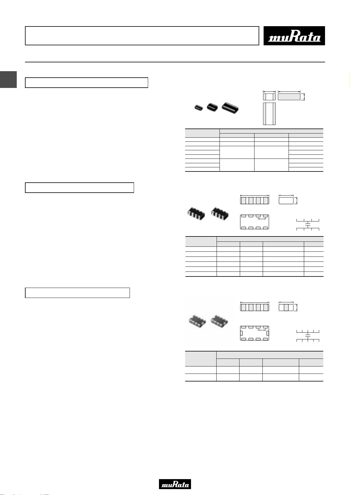
• This PDF catalog is downloaded from the website of Murata Manufacturing co., ltd. Therefore, it’s specifications are subject to change or our products in it may be discontinued without advance notice. Please check with our
!Note
• Please read rating and !CAUTION (for storage, operating, rating, soldering, mounting and handling) in this catalog to prevent smoking and/or burning, etc.
!Note
sales representatives or product engineers before ordering.
• This catalog has only typical specifications because there is no space for detailed specifications. Therefore, please approve our product specifications or transact the approval sheet for product specifications before ordering.
• This PDF catalog has only typical specifications because there is no space for detailed specifications. Therefore, please approve our product specifications or transact the approval sheet for product specifications before ordering.
Chip Monolithic Ceramic Capacitors
Low ESL LLL/LLA/LLM Series
C02E.pdf
09.9.18
3
Reversed Geometry Low ESL Type
■ Features
L
W
T
1. Low ESL, good for noise reduction for high
frequency
2. Small, high cap
■ Applications
1. High speed micro processor
2. High frequency digital equipment
Eight Terminals Low ESL Type
■ Features
1. Low ESL (100pH) , suitable to decoupling capacitor
for 1GHz clock speed IC.
Part Number
LLL153
LLL185
LLL215
LLL216
LLL219
LLL315
LLL317
LLL31M
L
0.8 ±0.1
1.25 ±0.1
1.6 ±0.15
Dimensions (mm)
L
q w e r
P
W
1.6 ±0.1
2.0 ±0.1
3.2 ±0.15
0.5 +0/-0.15
0.5 +0/-0.15
W
T
q e t u
T
0.3 ±0.050.5 ±0.05 1.0 ±0.05
0.6 max.
0.6 ±0.1
0.85 ±0.1
0.7 ±0.1
1.15 ±0.1
Equivalent Circuit
2. Small, large cap
■ Applications
1. High speed micro processor
2. High frequency digital equipment
Part Number
LLA185
LLA215
LLA219
LLA315
LLA319
LLA31M
i u y t
Dimensions (mm)
L W T
1.6 ±0.1 0.8 ±0.1 0.4 ±0.10.5 +0.05/-0.1
2.0 ±0.1 1.25 ±0.1 0.5 ±0.050.5 +0.05/-0.1
2.0 ±0.1 1.25 ±0.1 0.5 ±0.050.85 ±0.1
3.2 ±0.15 1.6 ±0.15 0.8 ±0.10.5 +0.05/-0.1
3.2 ±0.15 1.6 ±0.15 0.8 ±0.10.85 ±0.1
3.2 ±0.15 1.6 ±0.15 0.8 ±0.11.15 ±0.1
w r y i
P
Ten Terminals Low ESL Type
■ Features
1. Low ESL (45pH), suitable to decoupling capacitor
for 2GHz clock speed IC.
2. Small, large cap
■ Applications
1. High speed micro processor
2. High frequency digital equipment
Part Number
LLM215
LLM315
L
q w e r
P
o i u y
W
t!0
Dimensions (mm)
L W T
2.0 ±0.1 1.25 ±0.1 0.5 ±0.050.5 +0.05/-0.1
3.2 ±0.15 1.6 ±0.15 0.8 ±0.10.5 +0.05/-0.1
T
Equivalent Circuit
q e t u
w r y io!0
P
74
Page 77
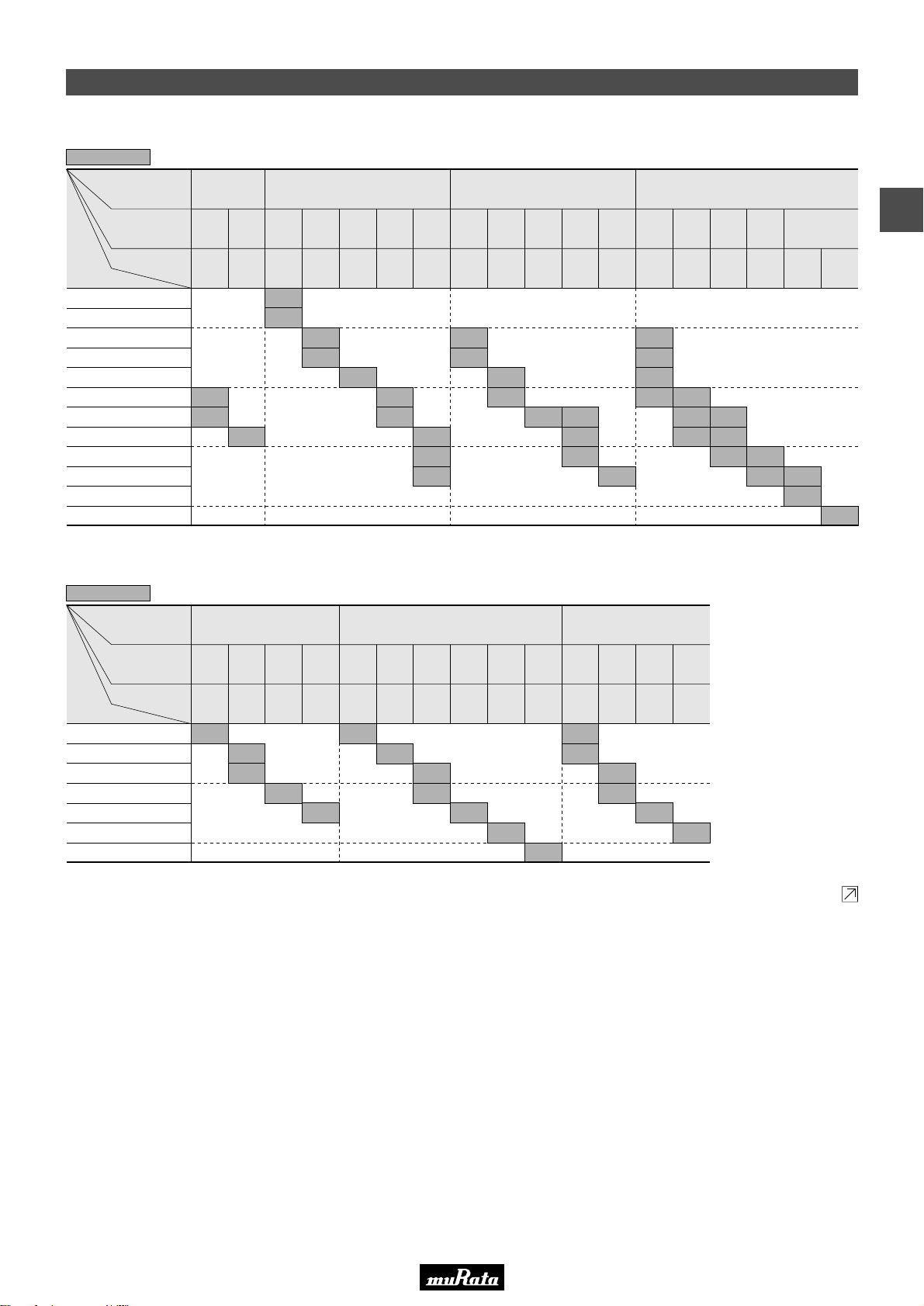
• This PDF catalog is downloaded from the website of Murata Manufacturing co., ltd. Therefore, it’s specifications are subject to change or our products in it may be discontinued without advance notice. Please check with our
!Note
• Please read rating and !CAUTION (for storage, operating, rating, soldering, mounting and handling) in this catalog to prevent smoking and/or burning, etc.
!Note
sales representatives or product engineers before ordering.
• This catalog has only typical specifications because there is no space for detailed specifications. Therefore, please approve our product specifications or transact the approval sheet for product specifications before ordering.
• This PDF catalog has only typical specifications because there is no space for detailed specifications. Therefore, please approve our product specifications or transact the approval sheet for product specifications before ordering.
Capacitance Table
Reversed Geometry Low ESL Type X7R(R7)/X7S(C7)/X6S(C8)/X5R(R6) Characteristics
5
Capacitance
10000pF(103)
22000pF(223)
47000pF(473)
The part number code is shown in ( ) and Unit is shown in [ ]. < >: EIA [inch] Code
ex.5: T Dimension [mm]
LxW
[mm]
Rated Voltage
[Vdc]
TC
2200pF(222)
4700pF(472)
0.10µF(104)
0.22µF(224)
0.47µF(474)
1.0µF(105)
2.2µF(225)
4.7µF(475)
10µF(106)
0.5x1.0
(15)
<0204>
6.3
(0J)
X6S
(C8)
3
3
4
(0G)
X7S
(C7)
3
50
(1H)
X7R
(R7)
5
5
25
(1E)
X7R
(R7)
5
5
0.8x1.6
(18)
<0306>
16
(1C)
X7R
(R7)
5
10
(1A)
X7R
(R7)
5
5
4
(0G)
X7S
(C7)
5
5
5
50
(1H)
X7R
(R7)
6
6
25
(1E)
X7R
(R7)
6
6
1.25x2.0
(21)
<0508>
16
(1C)
X7R
(R7)
9 6
10
(1A)
X7R
(R7)
9
9
4
(0G)
X7S
(C7)
9
50
(1H)
X7R
(R7)
7
7
7
M 7
25
(1E)
X7R
(R7)
MM7
1.6x3.2
(31)
<0612>
16
(1C)
X7R
(R7)
7
M 7
10
(1A)
X7R
(R7)
X7R
(R7)
M 7
C02E.pdf
09.9.18
6.3
(0J)
X5R
(R6)
M
M
3
Reversed Geometry Low ESL Type X7R(R7)/X7S(C7) Characteristics Low Profile
5
Capacitance
10000pF(103)
22000pF(223)
47000pF(473)
The part number code is shown in ( ) and Unit is shown in [ ]. < >: EIA [inch] Code
ex.5: T Dimension [mm]
LxW
[mm]
Rated Voltage
[Vdc]
TC
0.10µF(104)
0.22µF(224)
0.47µF(474)
1.0µF(105)
25
(1E)
X7R
(R7)
5
0.8x1.6
(18)
<0306>
16
(1C)
X7R
(R7)
5
5
10
(1A)
X7R
(R7)
5
4
(0G)
X7S
(C7)
5
50
(1H)
X7R
(R7)
5
25
(1E)
X7R
(R7)
5
1.25x2.0
(21)
<0508>
16
(1C)
X7R
(R7)
5
5
10
(1A)
X7R
(R7)
5
6.3
(0J)
X7R
(R7)
5
4
(0G)
X7S
(C7)
5
50
(1H)
X7R
(R7)
5
5
1.6x3.2
(31)
<0612>
25
(1E)
X7R
(R7)
5
5
16
10
(1C)
(1A)
X7R
X7R
(R7)
(R7)
5
5
Continued on the following page.
75
Page 78
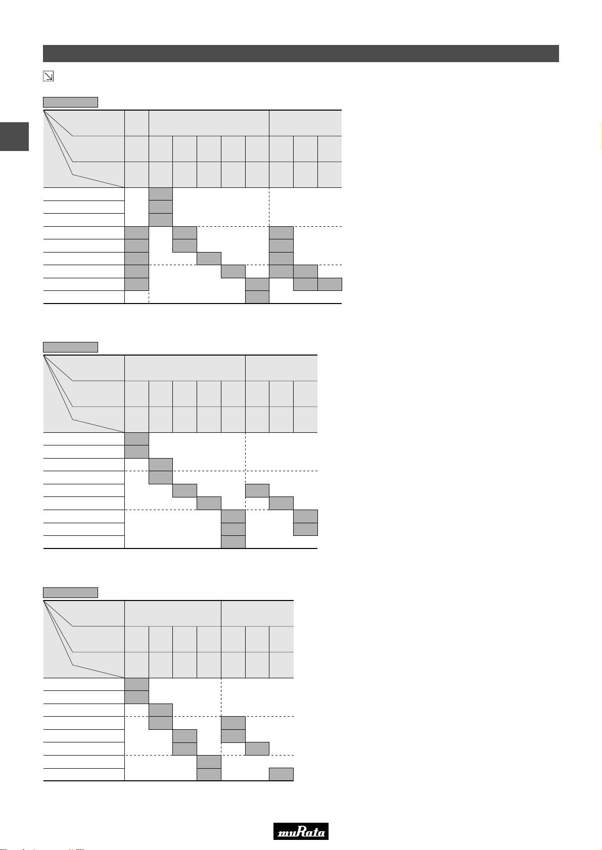
• This PDF catalog is downloaded from the website of Murata Manufacturing co., ltd. Therefore, it’s specifications are subject to change or our products in it may be discontinued without advance notice. Please check with our
!Note
• Please read rating and !CAUTION (for storage, operating, rating, soldering, mounting and handling) in this catalog to prevent smoking and/or burning, etc.
!Note
sales representatives or product engineers before ordering.
• This catalog has only typical specifications because there is no space for detailed specifications. Therefore, please approve our product specifications or transact the approval sheet for product specifications before ordering.
• This PDF catalog has only typical specifications because there is no space for detailed specifications. Therefore, please approve our product specifications or transact the approval sheet for product specifications before ordering.
Capacitance Table
Continued from the preceding page.
Eight Terminals Low ESL Type X7S(C7)/X7R(R7) Characteristics
5
3
Capacitance
10000pF(103)
22000pF(223)
47000pF(473)
The part number code is shown in ( ) and Unit is shown in [ ]. < >: EIA [inch] Code
ex.5: T Dimension [mm]
LxW
[mm]
Rated Voltage
[Vdc]
TC
0.10µF(104)
0.22µF(224)
0.47µF(474)
1.0µF(105)
2.2µF(225)
4.7µF(475)
1.6x0.8
(18)
<0603>
4
(0G)
X7S
(C7)
5
5
5
5
5
25
(1E)
X7R
(R7)
9
9
9
16
(1C)
X7R
(R7)
9
9
2.0x1.25
(21)
<0805>
10
(1A)
X7R
(R7)
9
6.3
(0J)
X7R
(R7)
9
4
(0G)
X7S
(C7)
9
9
16
(1C)
X7R
(R7)
9
9
9
M 9
3.2x1.6
(31)
<1206>
10
(1A)
X7R
(R7)
M 9
4
(0G)
X7R
(R7)
C02E.pdf
09.9.18
Eight Terminals Low ESL Type X7R(R7)/X7S(C7) Characteristics Low Profile
5
Capacitance
10000pF(103)
22000pF(223)
47000pF(473)
The part number code is shown in ( ) and Unit is shown in [ ]. < >: EIA [inch] Code
ex.5: T Dimension [mm]
LxW
[mm]
Rated Voltage
[Vdc]
TC
0.10µF(104)
0.22µF(224)
0.47µF(474)
1.0µF(105)
2.2µF(225)
4.7µF(475)
25
(1E)
X7R
(R7)
5
5
16
(1C)
X7R
(R7)
5
5
2.0x1.25
(21)
<0805>
10
(1A)
X7R
(R7)
5
6.3
(0J)
X7R
(R7)
5
4
(0G)
X7S
(C7)
5
5
5
16
(1C)
X7R
(R7)
5
3.2x1.6
(31)
<1206>
10
(1A)
X7R
(R7)
5
6.3
(0J)
X7R
(R7)
5
5
Ten Terminals Low ESL Type X7R(R7)/X7S(C7) Characteristics Low Profile
5
Capacitance
10000pF(103)
22000pF(223)
47000pF(473)
The part number code is shown in ( ) and Unit is shown in [ ]. < >: EIA [inch] Code
ex.5: T Dimension [mm]
LxW
[mm]
Rated Voltage
[Vdc]
TC
0.10µF(104)
0.22µF(224)
0.47µF(474)
1.0µF(105)
2.2µF(225)
25
(1E)
X7R
(R7)
5
5
2.0x1.25
(21)
<0805>
16
(1C)
X7R
(R7)
5
5
6.3
(0J)
X7R
(R7)
5
5
4
(0G)
X7S
(C7)
5
5
16
(1C)
X7R
(R7)
5
5
3.2x1.6
(31)
<1206>
10
(1A)
X7R
(R7)
5
6.3
(0J)
X7R
(R7)
5
76
Page 79
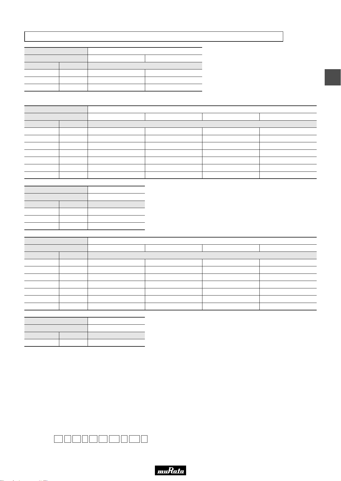
• This PDF catalog is downloaded from the website of Murata Manufacturing co., ltd. Therefore, it’s specifications are subject to change or our products in it may be discontinued without advance notice. Please check with our
!Note
• Please read rating and !CAUTION (for storage, operating, rating, soldering, mounting and handling) in this catalog to prevent smoking and/or burning, etc.
!Note
sales representatives or product engineers before ordering.
• This catalog has only typical specifications because there is no space for detailed specifications. Therefore, please approve our product specifications or transact the approval sheet for product specifications before ordering.
• This PDF catalog has only typical specifications because there is no space for detailed specifications. Therefore, please approve our product specifications or transact the approval sheet for product specifications before ordering.
Reversed Geometry Low ESL Type X7R(R7)/X7S(C7)/X6S(C8) Characteristics
C02E.pdf
09.9.18
LxW [mm]
Rated Volt. [Vdc]
Capacitance Tolerance Part Number
0.10µF(104)
0.22µF(224)
0.47µF(474)
LLL153 Series 4V/0.47µF(L: 0.5+0.07/-0.03mm)
LxW [mm]
Rated Volt. [Vdc]
Capacitance Tolerance Part Number
2200pF(222)
4700pF(472)
10000pF(103)
22000pF(223)
47000pF(473)
0.10µF(104)
0.22µF(224)
LxW [mm]
Rated Volt. [Vdc]
Capacitance Tolerance Part Number
0.47µF(474)
1.0µF(105)
2.2µF(225)
±20%(M)
±20%(M)
±20%(M)
±20%(M)
±20%(M)
±20%(M)
±20%(M)
±20%(M)
±20%(M)
±20%(M)
±20%(M)
±20%(M)
±20%(M)
LLL153C80J104ME01E*
LLL153C80J224ME14E*
LLL185R71H222MA01L
LLL185R71H472MA01L
0.8x1.6(18)<0306>
LLL185C70G474MA01L
LLL185C70G105ME02L*
LLL185C70G225ME01L*
0.5x1.0(15)<0204>
6.3(0J)
50(1H)
4(0G)
4(0G)
LLL153C70G474ME17E*
0.8x1.6(18)<0306>
25(1E)
LLL185R71E103MA01L
LLL185R71E223MA01L
LLL185R71C473MA01L
16(1C)
3
10(1A)
LLL185R71A104MA01L
LLL185R71A224MA01L
LxW [mm]
Rated Volt. [Vdc]
Capacitance Tolerance Part Number
10000pF(103)
22000pF(223)
47000pF(473)
0.10µF(104)
0.22µF(224)
0.47µF(474)
1.0µF(105)
LxW [mm]
Rated Volt. [Vdc]
Capacitance Tolerance Part Number
2.2µF(225) ±20%(M)
The part number code is shown in ( ) and Unit is shown in [ ]. < >: EIA [inch] Code
*: Please refer to LLL/LLA/LLM Series Specifications and Test Method(2).
±20%(M)
±20%(M)
±20%(M)
±20%(M)
±20%(M)
±20%(M)
±20%(M)
LLL219C70G225MA01L
50(1H)
LLL216R71H103MA01L
LLL216R71H223MA01L
LLL216R71E473MA01L
LLL216R71E104MA01L
1.25x2.0(21)<0508>
4(0G)
1.25x2.0(21)<0508>
25(1E)
LLL219R71C224MA01L
16(1C)
10(1A)
LLL216R71A224MA01L
LLL219R71A474MA01L
LLL219R71A105MA01L
(Part Number)
Packaging Code in Part Number is a code shows STD 180mm Reel Taping.
LL L 15 3 C8 0J 104 M E01 E
e r t y u i o !0
wq
qProduct ID wSeries eDimension (LxW) rDimension (T)
tTemperature Characteristics yRated Voltage uCapacitance
iCapacitance Tolerance oIndividual Specification Code !0Packaging
77
Page 80
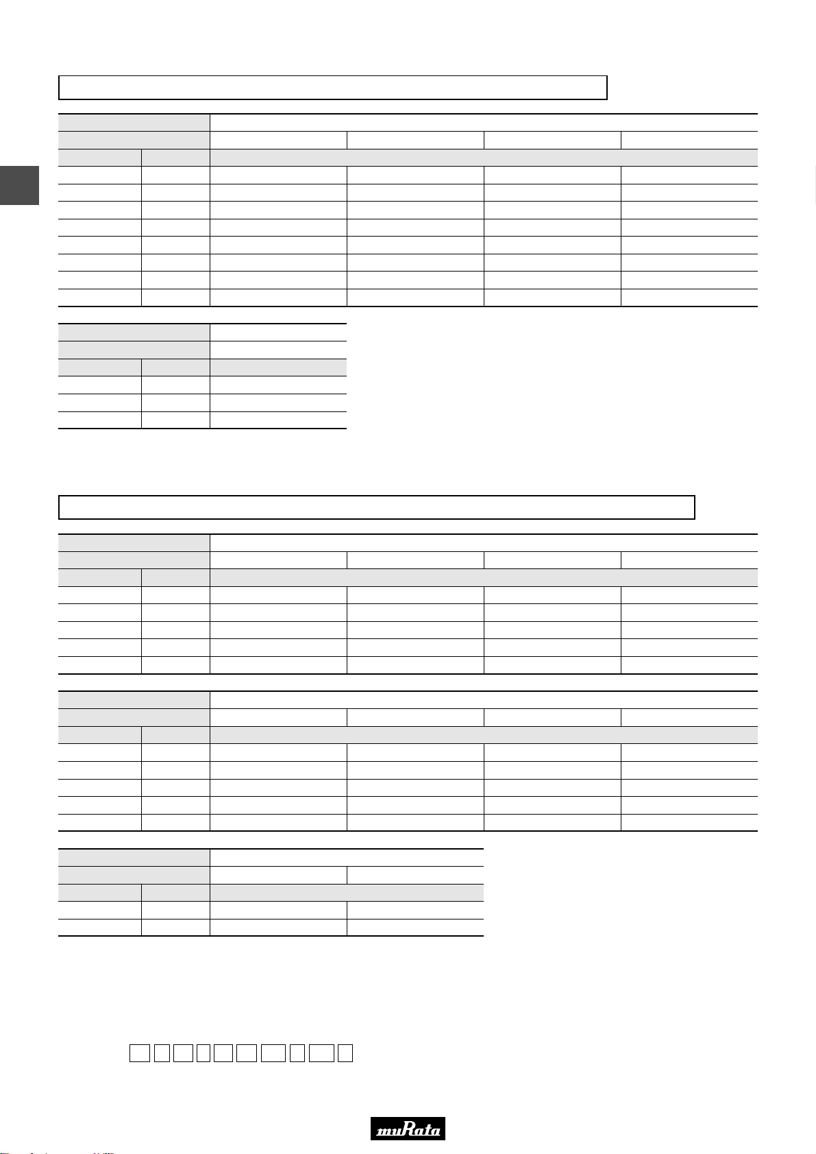
• This PDF catalog is downloaded from the website of Murata Manufacturing co., ltd. Therefore, it’s specifications are subject to change or our products in it may be discontinued without advance notice. Please check with our
!Note
• Please read rating and !CAUTION (for storage, operating, rating, soldering, mounting and handling) in this catalog to prevent smoking and/or burning, etc.
!Note
sales representatives or product engineers before ordering.
• This catalog has only typical specifications because there is no space for detailed specifications. Therefore, please approve our product specifications or transact the approval sheet for product specifications before ordering.
• This PDF catalog has only typical specifications because there is no space for detailed specifications. Therefore, please approve our product specifications or transact the approval sheet for product specifications before ordering.
Reversed Geometry Low ESL Type X7R(R7)/X5R(R6) Characteristics
C02E.pdf
09.9.18
LxW [mm]
Rated Volt. [Vdc]
Capacitance Tolerance Part Number
3
10000pF(103)
22000pF(223)
47000pF(473)
0.10µF(104)
0.22µF(224)
0.47µF(474)
1.0µF(105)
2.2µF(225)
LxW [mm]
Rated Volt. [Vdc]
Capacitance Tolerance Part Number
2.2µF(225)
4.7µF(475)
10µF(106)
The part number code is shown in ( ) and Unit is shown in [ ]. < >: EIA [inch] Code
*: Please refer to LLL/LLA/LLM Series Specifications and Test Method(2).
±20%(M)
±20%(M)
±20%(M)
±20%(M)
±20%(M)
±20%(M)
±20%(M)
±20%(M)
±20%(M)
±20%(M)
±20%(M)
LLL31MR71H104MA01L
LLL31MR70J475MA01L
LLL31MR60J106ME01L*
50(1H)
LLL317R71H103MA01L
LLL317R71H223MA01L
LLL317R71H473MA01L
LLL317R71E104MA01L
LLL31MR71E224MA01L
LLL31MR71E474MA01L
1.6x3.2(31)<0612>
6.3(0J)
LLL317R70J225MA01L
1.6x3.2(31)<0612>
25(1E)
16(1C)
LLL317R71C224MA01L
LLL317R71C474MA01L
LLL31MR71C105MA01L
10(1A)
LLL317R71A105MA01L
LLL31MR71A225MA01L
Reversed Geometry Low ESL Type X7R(R7)/X7S(C7) Characteristics Low Profile
LxW [mm]
Rated Volt. [Vdc]
Capacitance Tolerance Part Number
10000pF(103)
22000pF(223)
47000pF(473)
0.10µF(104)
0.22µF(224)
LxW [mm]
Rated Volt. [Vdc]
Capacitance Tolerance Part Number
10000pF(103)
22000pF(223)
47000pF(473)
0.10µF(104)
0.22µF(224)
LxW [mm]
Rated Volt. [Vdc]
Capacitance Tolerance Part Number
0.47µF(474)
1.0µF(105)
The part number code is shown in ( ) and Unit is shown in [ ]. < >: EIA [inch] Code
*: Please refer to LLL/LLA/LLM Series Specifications and Test Method(2).
±20%(M)
±20%(M)
±20%(M)
±20%(M)
±20%(M)
±20%(M)
±20%(M)
±20%(M)
±20%(M)
±20%(M)
±20%(M)
±20%(M)
25(1E)
LLL185R71E103MA11L
LLL185R71C223MA11L
LLL185R71C473MA11L
50(1H)
LLL215R71H103MA11L
LLL215R71E223MA11L
1.25x2.0(21)<0508>
6.3(0J)
LLL215R70J474MA11L
LLL215C70G105MA11L
0.8x1.6(18)<0306>
16(1C)
LLL185R71A104MA11L
1.25x2.0(21)<0508>
25(1E)
LLL215R71C473MA11L
LLL215R71C104MA11L
4(0G)
10(1A)
16(1C)
4(0G)
LLL185C70G224MA11L
10(1A)
LLL215R71A224MA11L
(Part Number)
Packaging Code in Part Number is a code shows STD 180mm Reel Taping.
LL L 31 7 R7 1H 103 M A01 L
e r t y u i o !0
wq
qProduct ID wSeries eDimension (LxW) rDimension (T)
tTemperature Characteristics yRated Voltage uCapacitance
iCapacitance Tolerance oIndividual Specification Code !0Packaging
78
Page 81

• This PDF catalog is downloaded from the website of Murata Manufacturing co., ltd. Therefore, it’s specifications are subject to change or our products in it may be discontinued without advance notice. Please check with our
!Note
• Please read rating and !CAUTION (for storage, operating, rating, soldering, mounting and handling) in this catalog to prevent smoking and/or burning, etc.
!Note
sales representatives or product engineers before ordering.
• This catalog has only typical specifications because there is no space for detailed specifications. Therefore, please approve our product specifications or transact the approval sheet for product specifications before ordering.
• This PDF catalog has only typical specifications because there is no space for detailed specifications. Therefore, please approve our product specifications or transact the approval sheet for product specifications before ordering.
Reversed Geometry Low ESL Type X7R(R7) Characteristics Low Profile
C02E.pdf
09.9.18
LxW [mm]
Rated Volt. [Vdc]
Capacitance Tolerance Part Number
10000pF(103)
22000pF(223)
47000pF(473)
0.10µF(104)
0.22µF(224)
0.47µF(474)
The part number code is shown in ( ) and Unit is shown in [ ]. < >: EIA [inch] Code
*: Please refer to LLL/LLA/LLM Series Specifications and Test Method(2).
±20%(M)
±20%(M)
±20%(M)
±20%(M)
±20%(M)
±20%(M)
50(1H)
LLL315R71H103MA11L
LLL315R71H223MA11L
LLL315R71E473MA11L
LLL315R71E104MA11L
1.6x3.2(31)<0612>
25(1E)
16(1C)
LLL315R71C224MA11L
Eight Terminals Low ESL Type X7R(R7)/X7S(C7) Characteristics
LxW [mm]
Rated Volt. [Vdc]
Capacitance Tolerance Part Number
0.10µF(104)
0.22µF(224)
0.47µF(474)
1.0µF(105)
2.2µF(225)
±20%(M)
±20%(M)
±20%(M)
±20%(M)
±20%(M)
1.6x0.8(18)<0603>
4(0G)
LLA185C70G104MA01L
LLA185C70G224MA01L
LLA185C70G474MA01L
LLA185C70G105ME01L*
LLA185C70G225ME16L*
10(1A)
3
LLL315R71A474MA11L
LxW [mm]
Rated Volt. [Vdc]
Capacitance Tolerance Part Number
10000pF(103)
22000pF(223)
47000pF(473)
0.10µF(104)
0.22µF(224)
0.47µF(474)
1.0µF(105)
LxW [mm]
Rated Volt. [Vdc]
Capacitance Tolerance Part Number
2.2µF(225)
4.7µF(475)
LxW [mm]
Rated Volt. [Vdc]
Capacitance Tolerance Part Number
0.10µF(104)
0.22µF(224)
0.47µF(474)
1.0µF(105)
2.2µF(225)
The part number code is shown in ( ) and Unit is shown in [ ]. < >: EIA [inch] Code
*: Please refer to LLL/LLA/LLM Series Specifications and Test Method(2).
±20%(M)
±20%(M)
±20%(M)
±20%(M)
±20%(M)
±20%(M)
±20%(M)
±20%(M)
±20%(M)
±20%(M)
±20%(M)
±20%(M)
±20%(M)
±20%(M)
LLA219R71E103MA01L
LLA219R71E223MA01L
LLA219R71E473MA01L
LLA219C70G225MA01L
LLA219C70G475ME01L*
LLA319R71C104MA01L
LLA319R71C224MA01L
LLA319R71C474MA01L
LLA31MR71C105MA01L
25(1E)
LLA219R71C104MA01L
LLA219R71C224MA01L
2.0x1.25(21)<0805>
4(0G)
3.2x1.6(31)<1206>
16(1C)
LLA319R71A105MA01L
LLA31MR71A225MA01L
2.0x1.25(21)<0805>
16(1C)
LLA219R71A474MA01L
10(1A)
LLA319R70G225MA01L
10(1A)
4(0G)
6.3(0J)
LLA219R70J105MA01L
79
Page 82

• This PDF catalog is downloaded from the website of Murata Manufacturing co., ltd. Therefore, it’s specifications are subject to change or our products in it may be discontinued without advance notice. Please check with our
!Note
• Please read rating and !CAUTION (for storage, operating, rating, soldering, mounting and handling) in this catalog to prevent smoking and/or burning, etc.
!Note
sales representatives or product engineers before ordering.
• This catalog has only typical specifications because there is no space for detailed specifications. Therefore, please approve our product specifications or transact the approval sheet for product specifications before ordering.
• This PDF catalog has only typical specifications because there is no space for detailed specifications. Therefore, please approve our product specifications or transact the approval sheet for product specifications before ordering.
Eight Terminals Low ESL Type X7R(R7)/X7S(C7) Characteristics Low Profile
C02E.pdf
09.9.18
LxW [mm]
Rated Volt. [Vdc]
Capacitance Tolerance Part Number
3
10000pF(103)
22000pF(223)
47000pF(473)
0.10µF(104)
0.22µF(224)
0.47µF(474)
LxW [mm]
Rated Volt. [Vdc]
Capacitance Tolerance Part Number
1.0µF(105)
2.2µF(225)
4.7µF(475)
LxW [mm]
Rated Volt. [Vdc]
Capacitance Tolerance Part Number
0.22µF(224)
0.47µF(474)
1.0µF(105)
2.2µF(225)
The part number code is shown in ( ) and Unit is shown in [ ]. < >: EIA [inch] Code
*: Please refer to LLL/LLA/LLM Series Specifications and Test Method(2).
±20%(M)
±20%(M)
±20%(M)
±20%(M)
±20%(M)
±20%(M)
±20%(M)
±20%(M)
±20%(M)
±20%(M)
±20%(M)
±20%(M)
±20%(M)
LLA215R71E103MA14L
LLA215R71E223MA14L
LLA215C70G105MA14L
LLA215C70G225ME11L*
LLA215C70G475ME19L*
LLA315R71C224MA14L
25(1E)
LLA215R71C473MA14L
LLA215R71C104MA14L
2.0x1.25(21)<0805>
4(0G)
3.2x1.6(31)<1206>
16(1C)
LLA315R71A474MA14L
2.0x1.25(21)<0805>
16(1C)
10(1A)
10(1A)
LLA215R71A224MA14L
6.3(0J)
LLA315R70J105MA14L
LLA315R70J225MA14L
6.3(0J)
LLA215R70J474MA14L
Ten Terminals Low ESL Type X7R(R7)/X7S(C7) Characteristics Low Profile
LxW [mm]
Rated Volt. [Vdc]
Capacitance Tolerance Part Number
10000pF(103)
22000pF(223)
47000pF(473)
0.10µF(104)
0.22µF(224)
0.47µF(474)
1.0µF(105)
2.2µF(225)
LxW [mm]
Rated Volt. [Vdc]
Capacitance Tolerance Part Number
0.10µF(104)
0.22µF(224)
0.47µF(474)
2.2µF(225)
The part number code is shown in ( ) and Unit is shown in [ ]. < >: EIA [inch] Code
*: Please refer to LLL/LLA/LLM Series Specifications and Test Method(2).
±20%(M)
±20%(M)
±20%(M)
±20%(M)
±20%(M)
±20%(M)
±20%(M)
±20%(M)
±20%(M)
±20%(M)
±20%(M)
±20%(M)
LLM215R71E103MA11L
LLM215R71E223MA11L
LLM315R71C104MA11L
LLM315R71C224MA11L
25(1E)
LLM215R71C473MA11L
LLM215R71C104MA11L
3.2x1.6(31)<1206>
16(1C)
LLM315R71A474MA11L
2.0x1.25(21)<0805>
16(1C)
10(1A)
6.3(0J)
LLM215R70J224MA11L
LLM215R70J474MA11L
6.3(0J)
LLM315R70J225MA11L
4(0G)
LLM215C70G105MA11L
LLM215C70G225ME11L*
(Part Number)
Packaging Code in Part Number is a code shows STD 180mm Reel Taping.
LL A 21 5 R7 1E 103 M A14 L
e r t y u i o !0
wq
qProduct ID wSeries eDimension (LxW) rDimension (T)
tTemperature Characteristics yRated Voltage uCapacitance
iCapacitance Tolerance oIndividual Specification Code !0Packaging
80
Page 83

In case Non "*" is added in PNs table, please refer to LLL/LLA/LLM Series Specifications and Test Methods (1).
In case "*" is added in PNs table, please refer to LLL/LLA/LLM Series Specifications and Test Methods (2).
LLL/LLA/LLM Series Specifications and Test Methods (1)
R7, C7: Y55 to W125°C
Operating
Temperature
Range
1
Item
No. Test Method
See the previous pages.
Within the specified dimension
No defects or abnormalities
CV0.047µF: More than 10,000MΩ
CG0.047µF: More than 500Ω · F
C: Normal Capacitance
No defects or abnormalities
Rated Voltage
Appearance
Dimensions
Dielectric Strength
Insulation
Resistance
2
3
4
5
6
Using calipers
The insulation resistance should be measured with a DC voltage
not exceeding the rated voltage at 25°C and 75%RH max. and
within 2 minutes of charging.
No failure should be observed when 250% of the rated voltage
is applied between the terminations for 1 to 5 seconds,
provided the charge/discharge current is less than 50mA.
Visual inspection
The rated voltage is defined as the maximum voltage which
may be applied continuously to the capacitor.
When AC voltage is superimposed on DC voltage, V
P-P
or V
O-P
,
whichever is larger, should be maintained within the rated
voltage range.
Continued on the following page.
Specifications
Within the specified tolerance
W.V.: 25V min.; 0.025 max.
W.V.: 16V/10V max.; 0.035 max.
W.V.: 6.3V max.; 0.05 max.
Capacitance
Dissipation Factor
(D.F.)
7
8
The capacitance/D.F. should be measured at 25°C at the
frequency and voltage shown in the table.
Frequency: 1T0.1kHz
Voltage: 1T0.2Vrms
*For LLA185C70G474, the capacitance should be measured
unsing a voltage of 0.5±0.1Vrms.
Capacitance
Temperature
Characteristics
9
The capacitance change should be measured after 5 min. at
each specified temperature stage.
The ranges of capacitance change compared with the 25°C
value over the temperature ranges shown in the table should
be within the specified ranges.
• Initial measurement.
Perform a heat treatment at 150+0/-10°C for one hour and then
set for 24±2 hours at room temperature. Perform the initial
measurement.
Step
Temperature (°C)
1
2
3
4
5
25T2
Y55T3
25T2
125T3
25T2
No removal of the terminations or other defect should occur.
Adhesive Strength
of Termination
10
Solder the capacitor to the test jig (glass epoxy board) using a
eutectic solder. Then apply 10N* force in parallel with the test
jig for 10T1 sec. The soldering should be done either with an
iron or using the reflow method and should be conducted with
care so that the soldering is uniform and free of defects such as
heat shock. *LLL18 and LLA/LLM Series: 5N
75% of the terminations are to be soldered evenly
and continuously.
Solderability of
Termination
12
Immerse the capacitor in a solution of ethanol (JIS-K-8101) and
rosin (JIS-K-5902) (25% rosin in weight proportion). Preheat at
80 to 120°C for 10 to 30 seconds. After preheating, immerse in
eutectic solder solution for 2T0.5 seconds at 230T5°C, or
Sn-3.0Ag-0.5Cu solder solution for 2T0.5 seconds at 245T5°C.
More than 10,000MΩ or 500Ω · F (Whichever is smaller)
Within T7.5%
W.V.: 25V min.; 0.025 max.
W.V.: 16V/10V max.; 0.035 max.
W.V.: 6.3V max.; 0.05 max.
Appearance
I.R.
Capacitance
Change
D.F.
No marking defects
Resistance
to Soldering
Heat
13
Preheat the capacitor at 120 to 150°C for 1 minute. Immerse
the capacitor in a eutectic solder or Sn-3.0Ag-0.5Cu solder
solution at 270T5°C for 10T0.5 seconds. Let sit at room
temperature for 24T2 hours, then measure.
• Initial measurement.
Perform a heat treatment at 150 °C for one hour and then
let sit for 24T2 hours at room temperature. Perform the initial
measurement.
+0
–10
No failure
Dielectric
Strength
No defects or abnormalities
Within the specified tolerance
W.V.: 25V min.; 0.025 max.
W.V.: 16V/10V max.; 0.035 max.
W.V.: 6.3V max.; 0.05 max.
Vibration
Resistance
11
Solder the capacitor to the test jig (glass epoxy board) in
the same manner and under the same conditions as (10). The
capacitor should be subjected to a simple harmonic motion
having a total amplitude of 1.5mm, the frequency being varied
uniformly between the approximate limits of 10 and 55Hz. The
frequency range, from 10 to 55Hz and return to 10Hz, should
be traversed in approximately 1 minute. This motion should be
applied for a period of 2 hours in each of 3 mutually
perpendicular directions (total of 6 hours).
Appearance
Capacitance
D.F.
Char.
Temp. Range
(°C)
Reference
Temp.
Cap.Change
R7
C7
Y55 to +125
Y55 to +125
25°C
25°C
Within T15%
Within T22%
• This PDF catalog is downloaded from the website of Murata Manufacturing co., ltd. Therefore, it’s specifications are subject to change or our products in it may be discontinued without advance notice. Please check with our
!Note
• Please read rating and !CAUTION (for storage, operating, rating, soldering, mounting and handling) in this catalog to prevent smoking and/or burning, etc.
!Note
sales representatives or product engineers before ordering.
• This catalog has only typical specifications because there is no space for detailed specifications. Therefore, please approve our product specifications or transact the approval sheet for product specifications before ordering.
• This PDF catalog has only typical specifications because there is no space for detailed specifications. Therefore, please approve our product specifications or transact the approval sheet for product specifications before ordering.
C02E.pdf
09.9.18
LLL/LLA/LLM Series Specifications and Test Methods (1)
3
81
Page 84
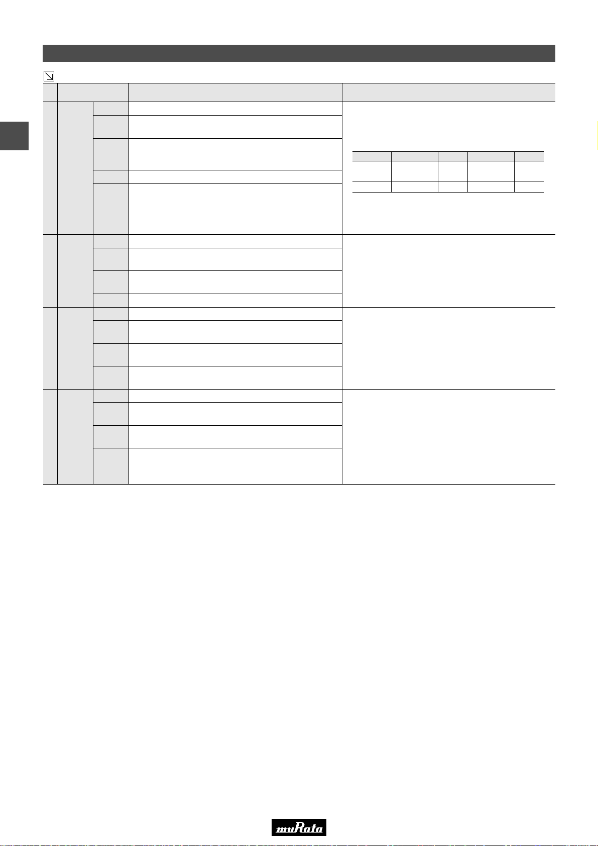
In case Non "*" is added in PNs table, please refer to LLL/LLA/LLM Series Specifications and Test Methods (1).
In case "*" is added in PNs table, please refer to LLL/LLA/LLM Series Specifications and Test Methods (2).
LLL/LLA/LLM Series Specifications and Test Methods (1)
ItemNo. Test Method
Specifications
More than 10,000MΩ or 500Ω · F (Whichever is smaller)
Within T7.5%
W.V.: 25V min.; 0.025 max.
W.V.: 16V/10V max.; 0.035 max.
W.V.: 6.3V max.; 0.05 max.
Appearance
I.R.
Capacitance
Change
D.F.
No marking defects
Temperature
Cycle
14
Fix the capacitor to the supporting jig in the same manner and
under the same conditions as (10).
Perform the five cycles according to the four heat treatments
listed in the following table. Let sit for 24T2 hours at room
temperature, then measure.
• Initial measurement.
Perform a heat treatment at 150 °C for one hour and then
let sit for 24T2 hours at room temperature. Perform the initial
measurement.
+0
–10
No failure
Dielectric
Strength
More than 1,000MΩ or 50Ω · F (Whichever is smaller)
Within T12.5%
W.V.: 10V min.; 0.05 max.
W.V.: 6.3V max.; 0.075 max.
Appearance
I.R.
Capacitance
Change
D.F.
No marking defects
Humidity
(Steady
State)
15
Sit the capacitor at 40T2°C and 90 to 95% humidity for 500T12
hours. Remove and let sit for 24T2 hours at room temperature,
then measure.
Step 1 2 3 4
Temp. (°C)
Time (min.)
Min. Operating
Temp.
+0
–3
Room
Temp.
Max. Operating
Temp.
+3
–0
Room
Temp.
30T3
2 to 3
30T3
2 to 3
More than 1,000MΩ or 50Ω · F
(Whichever is smaller)
Appearance
I.R.
Capacitance
Change
D.F.
No marking defects
High
Temperature
Load
17
Apply 200% of the rated voltage for 1000T12 hours at the
maximum operating temperature T3°C. Let sit for 24T2 hours
at room temperature, then measure. The charge/discharge
current is less than 50mA.
•Initial measurement.
Apply 200% of the rated DC voltage for one hour at the
maximum operating temperature T3°C. Remove and let sit for
24T2 hours at room temperature.
Perform initial measurement.
Within T12.5%
W.V.: 10V min.; 0.05 max.
W.V.: 6.3V max.; 0.075 max.
More than 500MΩ or 25Ω · F
(Whichever is smaller)
Within T12.5%
W.V.: 10V min.; 0.05 max.
W.V.: 6.3V max.; 0.075 max.
Appearance
I.R.
Capacitance
Change
D.F.
No marking defects
Humidity
Load
16
Apply the rated voltage at 40T2°C and 90 to 95% humidity for
500T12 hours. Remove and let sit for 24T2 hours at room
temperature, then measure. The charge/discharge current is
less than 50mA.
• This PDF catalog is downloaded from the website of Murata Manufacturing co., ltd. Therefore, it’s specifications are subject to change or our products in it may be discontinued without advance notice. Please check with our
!Note
3
• Please read rating and !CAUTION (for storage, operating, rating, soldering, mounting and handling) in this catalog to prevent smoking and/or burning, etc.
!Note
sales representatives or product engineers before ordering.
• This catalog has only typical specifications because there is no space for detailed specifications. Therefore, please approve our product specifications or transact the approval sheet for product specifications before ordering.
• This PDF catalog has only typical specifications because there is no space for detailed specifications. Therefore, please approve our product specifications or transact the approval sheet for product specifications before ordering.
LLL/LLA/LLM Series Specifications and Test Methods (1)
Continued from the preceding page.
C02E.pdf
09.9.18
82
Page 85
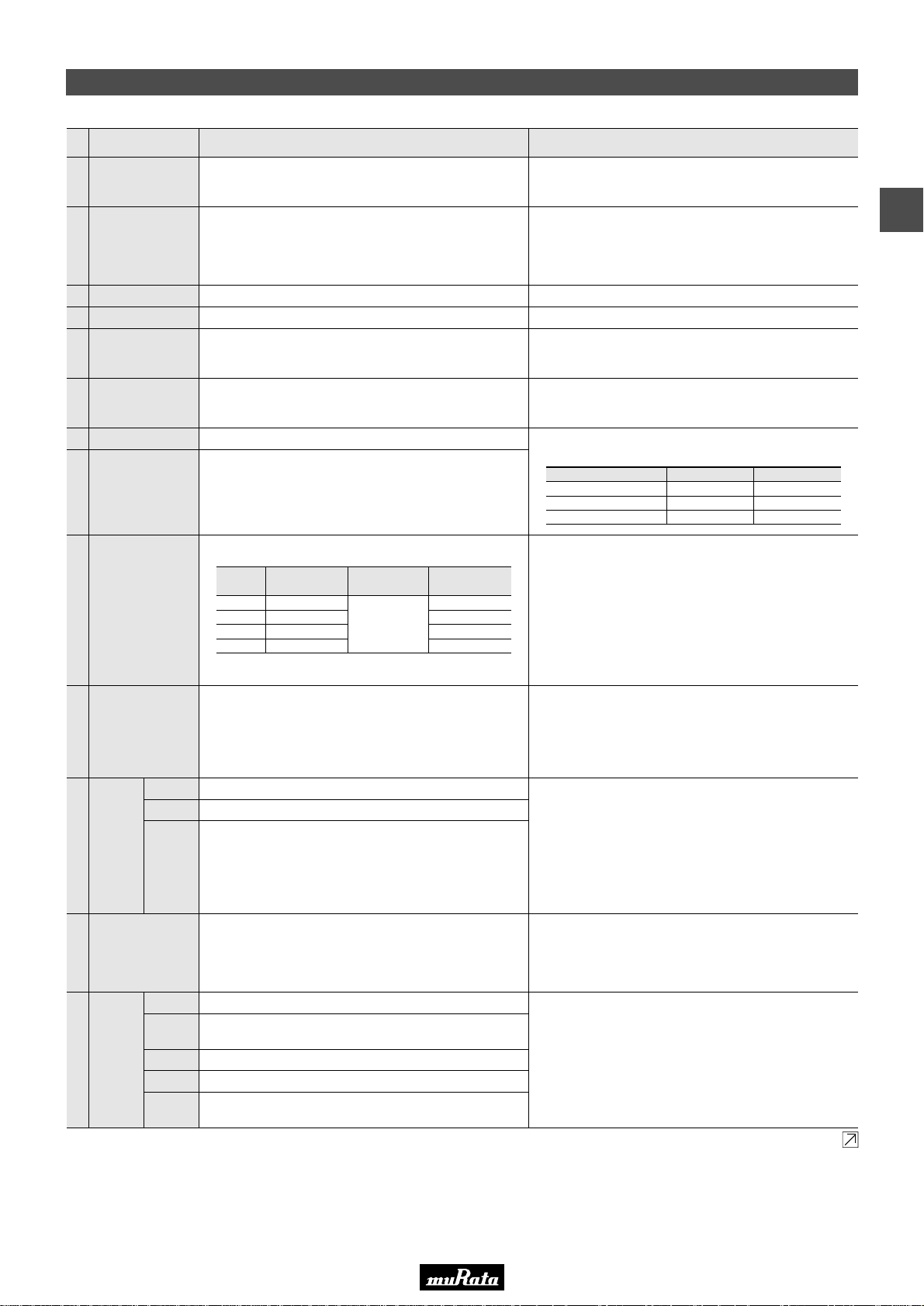
In case Non "*" is added in PNs table, please refer to LLL/LLA/LLM Series Specifications and Test Methods (1).
In case "*" is added in PNs table, please refer to LLL/LLA/LLM Series Specifications and Test Methods (2).
Preheat the capacitor at 120 to 150°C for 1 minute. Immerse
the capacitor in a eutectic solder or Sn-3.0Ag-0.5Cu solder
solution at 270±5°C for 10±0.5 seconds.
Let sit at room temperature for 24±2 hours, then measure.
• Initial measurement.
Perform a heat treatment at 150
+–0
10
°C for one hour and then
let sit for 24±2 hours at room temperature. Perform the initial
measurement.
13
Resistance
to Soldering
Heat
Appearance
No marking defects
Capacitance
Change
R6, R7, C7, C8: Within ±7.5%
D.F. R6, R7, C7, C8: 0.120 max.
I.R. 50Ω · F min.
Dielectric
Strength
No failure
Immerse the capacitor in a solution of ethanol (JIS-K-8101) and
rosin (JIS-K-5902) (25% rosin in weight proportion). Preheat at
80 to 120°C for 10 to 30 seconds. After preheating, immerse in
eutectic solder solution for 2±0.5 seconds at 230±5°C, or
Sn-3.0Ag-0.5Cu solder solution for 2±0.5 seconds at 245±5°C.
12
Solderability of
Termination
75% of the terminations are to be soldered evenly
and continuously.
Solder the capacitor to the test jig (glass epoxy board) in
the same manner and under the same conditions as (10). The
capacitor should be subjected to a simple harmonic motion
having a total amplitude of 1.5mm, the frequency being varied
uniformly between the approximate limits of 10 and 55Hz. The
frequency range, from 10 to 55Hz and return to 10Hz, should
be traversed in approximately 1 minute. This motion should be
applied for a period of 2 hours in each of 3 mutually
perpendicular directions (total of 6 hours).
11
Vibration
Appearance
No defects or abnormalities
Capacitance
Within the specified tolerance
D.F. R6, R7, C7, C8: 0.120 max.
Solder the capacitor to the test jig (glass epoxy board) using a
eutectic solder. Then apply 10N* force in parallel with the test
jig for 10±1 sec. The soldering should be done either with an
iron or using the reflow method and should be conducted with
care so that the soldering is uniform and free of defects such as
heat shock. *5N (LLL15, LLL18, LLA,LLM Series)
10
Adhesive Strength
of Termination
No removal of the terminations or other defect should occur.
The capacitance change should be measured after 5 min. at
each specified temperature stage.
The ranges of capacitance change compared with the 25°C
value over the temperature ranges shown in the table should
be within the specified ranges.
• Initial measurement.
Perform a heat treatment at 150+0/-10°C for one hour and then
set for 24±2 hours at room temperature. Perform the initial
measurement.
9
Capacitance
Temperature
Characteristics
8
Dissipation Factor
(D.F.)
R6, R7, C7, C8: 0.120 max.
The capacitance/D.F. should be measured at 25°C at the
frequency and voltage shown in the table.
7 Capacitance Within the specified tolerance
The insulation resistance should be measured with a DC voltage
not exceeding the rated voltage at 25°C and 75%RH max. and
within 1 minute of charging.
6
Insulation
Resistance
50Ω · F min.
No failure should be observed when 250% of the rated voltage
is applied between the terminations for 1 to 5 seconds,
provided the charge/discharge current is less than 50mA.
5 Dielectric Strength No defects or abnormalities
Using calipers4 Dimensions Within the specified dimension
Visual inspection3 Appearance No defects or abnormalities
The rated voltage is defined as the maximum voltage which
may be applied continuously to the capacitor.
When AC voltage is superimposed on DC voltage, V
P-P
or V
O-P
,
whichever is larger, should be maintained within the rated
voltage range.
2 Rated Voltage See the previous pages.
1
Operating
Temperature
Range
R6: –55 to +85°C
R7, C7: –55 to +125°C
C8: –55 to +105°C
No. Test MethodSpecificationsItem
Continued on the following page.
Temp. Range
(°C)
Char.
–55 to +85
–55 to +125
–55 to +125
–55 to +105
Reference
Temp.
25°C
Cap. Change
Within ±15%
Within ±15%
Within ±22%
Within ±22%
R6
R7
C7
C8
FrequencyCapacitance
1±0.1kHz
1±0.1kHz
120±24Hz
Voltage
1.0±0.2Vrms
0.5±0.1Vrms
0.5±0.1Vrms
CV10µF (10V min.)
CV10µF (6.3V max.)
C>10µF
LLL/LLA/LLM Series Specifications and Test Methods (2)
• This PDF catalog is downloaded from the website of Murata Manufacturing co., ltd. Therefore, it’s specifications are subject to change or our products in it may be discontinued without advance notice. Please check with our
!Note
• Please read rating and !CAUTION (for storage, operating, rating, soldering, mounting and handling) in this catalog to prevent smoking and/or burning, etc.
!Note
sales representatives or product engineers before ordering.
• This catalog has only typical specifications because there is no space for detailed specifications. Therefore, please approve our product specifications or transact the approval sheet for product specifications before ordering.
• This PDF catalog has only typical specifications because there is no space for detailed specifications. Therefore, please approve our product specifications or transact the approval sheet for product specifications before ordering.
C02E.pdf
09.9.18
LLL/LLA/LLM Series Specifications and Test Methods (2)
3
83
Page 86
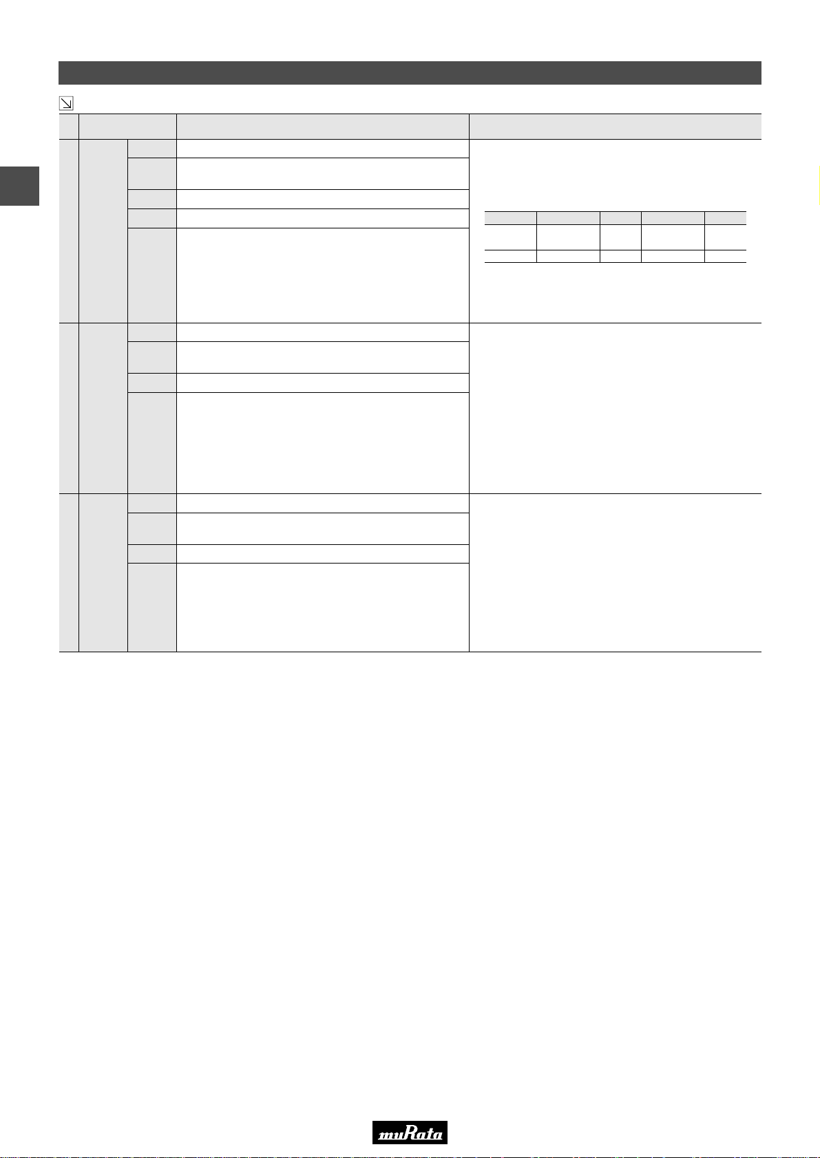
In case Non "*" is added in PNs table, please refer to LLL/LLA/LLM Series Specifications and Test Methods (1).
In case "*" is added in PNs table, please refer to LLL/LLA/LLM Series Specifications and Test Methods (2).
Apply 150% of the rated voltage for 1000±12 hours at the
maximum operating temperature ±3°C.
The charge/discharge current is less than 50mA.
•Initial measurement
Perform a heat treatment at 150
+–0
10
°C for one hour and then
let sit for 24±2 hours at room temperature. Perform the initial
measurement.
•Measurement after test
Perform a heat treatment at 150
+–0
10
°C for one hour and then
let sit for 24±2 hours at room temperature, then measure.
16
Durability
Appearance
No marking defects
Capacitance
Change
R6, R7, C7, C8: Within ±12.5%
* LLL153C70G474: Within ±20%
D.F. R6, R7, C7, C8: 0.2 max.
I.R. 25Ω · F min.
Apply the rated voltage at 40±2°C and 90 to 95% humidity for
500±12 hours.
The charge/discharge current is less than 50mA.
Apply the rated DC voltage.
•Initial measurement
Perform a heat treatment at 150
+–0
10
°C for one hour and then
let sit for 24±2 hours at room temperature. Perform the initial
measurement.
•Measurement after test
Perform a heat treatment at 150
+–0
10
°C for one hour and then
let sit for 24±2 hours at room temperature, then measure.
15
High
Temperature
High
Humidity
(Steady
State)
Appearance
No marking defects
Capacitance
Change
R6, R7, C7, C8: Within ±12.5%
D.F. R6, R7, C7, C8: 0.2 max.
I.R. 12.5Ω · F min.
Fix the capacitor to the supporting jig in the same manner and
under the same conditions as (10).Perform the five cycles
according to the four heat treatments listed in the following
table. Let sit for 24±2 hours at room temperature,
then measure.
• Initial measurement
Perform a heat treatment at 150
+–0
10
°C for one hour and then
let sit for 24±2 hours at room temperature. Perform the initial
measurement.
14
Temperature
Sudden
Change
Appearance
No marking defects
Capacitance
Change
R6, R7, C7, C8: Within ±12.5%
D.F. R6, R7, C7, C8: 0.120 max.
I.R. 50Ω · F min.
Dielectric
Strength
No failure
No. Test MethodSpecificationsItem
Continued from the preceding page.
LLL/LLA/LLM Series Specifications and Test Methods (2)
1Step
Min. Operating
Temp.
+–0
3
30±3
2
Room
Temp.
2 to 3
3
Min. Operating
Temp.
+–0
3
30±3
4
Room
Temp.
2 to 3
Temp. (°C)
Time (min.)
• This PDF catalog is downloaded from the website of Murata Manufacturing co., ltd. Therefore, it’s specifications are subject to change or our products in it may be discontinued without advance notice. Please check with our
!Note
• Please read rating and !CAUTION (for storage, operating, rating, soldering, mounting and handling) in this catalog to prevent smoking and/or burning, etc.
!Note
sales representatives or product engineers before ordering.
• This catalog has only typical specifications because there is no space for detailed specifications. Therefore, please approve our product specifications or transact the approval sheet for product specifications before ordering.
• This PDF catalog has only typical specifications because there is no space for detailed specifications. Therefore, please approve our product specifications or transact the approval sheet for product specifications before ordering.
LLL/LLA/LLM Series Specifications and Test Methods (2)
3
C02E.pdf
09.9.18
84
Page 87

• This PDF catalog is downloaded from the website of Murata Manufacturing co., ltd. Therefore, it’s specifications are subject to change or our products in it may be discontinued without advance notice. Please check with our
!Note
• Please read rating and !CAUTION (for storage, operating, rating, soldering, mounting and handling) in this catalog to prevent smoking and/or burning, etc.
!Note
sales representatives or product engineers before ordering.
• This catalog has only typical specifications because there is no space for detailed specifications. Therefore, please approve our product specifications or transact the approval sheet for product specifications before ordering.
• This PDF catalog has only typical specifications because there is no space for detailed specifications. Therefore, please approve our product specifications or transact the approval sheet for product specifications before ordering.
Chip Monolithic Ceramic Capacitors
High-Q Type GJM Series
C02E.pdf
09.9.18
■ Features
1. Mobile Telecommunication and RF module, mainly
2. Quality improvement of telephone call, Low power
Consumption, yield ratio improvement
■ Applications
VCO, PA, Mobile Telecommunication
Part Number
GJM03
GJM15
e eg
L
Dimensions (mm)
L W T
0.6 ±0.03 0.3 ±0.03 0.1 to 0.2 0.20.3 ±0.03
1.0 ±0.05 0.5 ±0.05 0.15 to 0.3 0.40.5 ±0.05
4
T
W
e g min.
85
Page 88
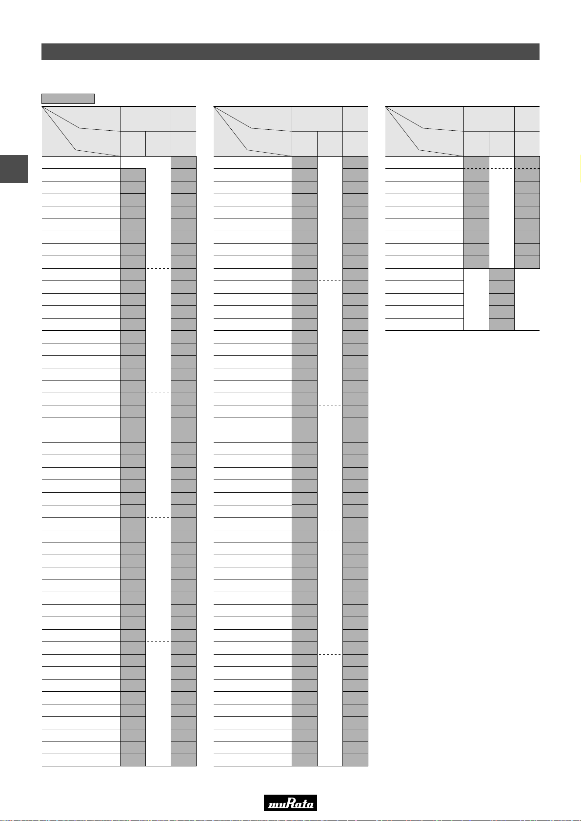
• This PDF catalog is downloaded from the website of Murata Manufacturing co., ltd. Therefore, it’s specifications are subject to change or our products in it may be discontinued without advance notice. Please check with our
!Note
• Please read rating and !CAUTION (for storage, operating, rating, soldering, mounting and handling) in this catalog to prevent smoking and/or burning, etc.
!Note
sales representatives or product engineers before ordering.
• This catalog has only typical specifications because there is no space for detailed specifications. Therefore, please approve our product specifications or transact the approval sheet for product specifications before ordering.
• This PDF catalog has only typical specifications because there is no space for detailed specifications. Therefore, please approve our product specifications or transact the approval sheet for product specifications before ordering.
Capacitance Table
Temperature Compensating Type C0G(5C)/C0H(6C) Characteristics
3
Capacitance
4
The part number code is shown in ( ) and Unit is shown in [ ]. < >: EIA [inch] Code
ex.3: T Dimension [mm]
LxW
[mm]
Rated Voltage
[Vdc]
0.1pF(R10)
0.2pF(R20)
0.3pF(R30)
0.4pF(R40)
0.5pF(R50)
0.6pF(R60)
0.7pF(R70)
0.8pF(R80)
0.9pF(R90)
1.0pF(1R0)
1.1pF(1R1)
1.2pF(1R2)
1.3pF(1R3)
1.4pF(1R4)
1.5pF(1R5)
1.6pF(1R6)
1.7pF(1R7)
1.8pF(1R8)
1.9pF(1R9)
2.0pF(2R0)
2.1pF(2R1)
2.2pF(2R2)
2.3pF(2R3)
2.4pF(2R4)
2.5pF(2R5)
2.6pF(2R6)
2.7pF(2R7)
2.8pF(2R8)
2.9pF(2R9)
3.0pF(3R0)
3.1pF(3R1)
3.2pF(3R2)
3.3pF(3R3)
3.4pF(3R4)
3.5pF(3R5)
3.6pF(3R6)
3.7pF(3R7)
3.8pF(3R8)
3.9pF(3R9)
4.0pF(4R0)
4.1pF(4R1)
4.2pF(4R2)
4.3pF(4R3)
4.4pF(4R4)
4.5pF(4R5)
4.6pF(4R6)
4.7pF(4R7)
4.8pF(4R8)
4.9pF(4R9)
0.6x0.3
<0201>
25
(1A)
3
3
3
3
3
3
3
3
3
3
3
3
3
3
3
3
3
3
3
3
3
3
3
3
3
3
3
3
3
3
3
3
3
3
3
3
3
3
3
3
3
3
3
3
3
3
3
3
(03)
6.3
(0J)50(1H)
1.0x0.5
(15)
<0402>
5
5
5
5
5
5
5
5
5
5
5
5
5
5
5
5
5
5
5
5
5
5
5
5
5
5
5
5
5
5
5
5
5
5
5
5
5
5
5
5
5
5
5
5
5
5
5
5
5
Capacitance
LxW
[mm]
Rated Voltage
[Vdc]
5.0pF(5R0)
5.1pF(5R1)
5.2pF(5R2)
5.3pF(5R3)
5.4pF(5R4)
5.5pF(5R5)
5.6pF(5R6)
5.7pF(5R7)
5.8pF(5R8)
5.9pF(5R9)
6.0pF(6R0)
6.1pF(6R1)
6.2pF(6R2)
6.3pF(6R3)
6.4pF(6R4)
6.5pF(6R5)
6.6pF(6R6)
6.7pF(6R7)
6.8pF(6R8)
6.9pF(6R9)
7.0pF(7R0)
7.1pF(7R1)
7.2pF(7R2)
7.3pF(7R3)
7.4pF(7R4)
7.5pF(7R5)
7.6pF(7R6)
7.7pF(7R7)
7.8pF(7R8)
7.9pF(7R9)
8.0pF(8R0)
8.1pF(8R1)
8.2pF(8R2)
8.3pF(8R3)
8.4pF(8R4)
8.5pF(8R5)
8.6pF(8R6)
8.7pF(8R7)
8.8pF(8R8)
8.9pF(8R9)
9.0pF(9R0)
9.1pF(9R1)
9.2pF(9R2)
9.3pF(9R3)
9.4pF(9R4)
9.5pF(9R5)
9.6pF(9R6)
9.7pF(9R7)
9.8pF(9R8)
0.6x0.3
(03)
<0201>
25
(1A)
3
3
3
3
3
3
3
3
3
3
3
3
3
3
3
3
3
3
3
3
3
3
3
3
3
3
3
3
3
3
3
3
3
3
3
3
3
3
3
3
3
3
3
3
3
3
3
3
3
1.0x0.5
(15)
<0402>
6.3
(0J)50(1H)
5
5
5
5
5
5
5
5
5
5
5
5
5
5
5
5
5
5
5
5
5
5
5
5
5
5
5
5
5
5
5
5
5
5
5
5
5
5
5
5
5
5
5
5
5
5
5
5
5
Capacitance
LxW
[mm]
Rated Voltage
[Vdc]
9.9pF(9R9)
10pF(100)
11pF(110)
12pF(120)
13pF(130)
15pF(150)
16pF(160)
18pF(180)
20pF(200)
22pF(220)
24pF(240)
27pF(270)
30pF(300)
33pF(330)
25
(1A)
0.6x0.3
(03)
<0201>
3
3
3
3
3
3
3
3
3
C02E.pdf
09.9.18
1.0x0.5
(15)
<0402>
6.3
(0J)50(1H)
5
5
5
5
5
5
5
5
5
3
3
3
3
3
86
Page 89

• This PDF catalog is downloaded from the website of Murata Manufacturing co., ltd. Therefore, it’s specifications are subject to change or our products in it may be discontinued without advance notice. Please check with our
!Note
• Please read rating and !CAUTION (for storage, operating, rating, soldering, mounting and handling) in this catalog to prevent smoking and/or burning, etc.
!Note
sales representatives or product engineers before ordering.
• This catalog has only typical specifications because there is no space for detailed specifications. Therefore, please approve our product specifications or transact the approval sheet for product specifications before ordering.
• This PDF catalog has only typical specifications because there is no space for detailed specifications. Therefore, please approve our product specifications or transact the approval sheet for product specifications before ordering.
Temperature Compensating Type C0G(5C) Characteristics
C02E.pdf
09.9.18
LxW [mm]
Rated Volt. [Vdc]
Capacitance Tolerance Part Number
0.1pF(R10)
0.2pF(R20)
0.3pF(R30)
0.4pF(R40)
0.5pF(R50)
0.6pF(R60)
0.7pF(R70)
0.8pF(R80)
0.9pF(R90)
1.0pF(1R0)
1.1pF(1R1)
1.2pF(1R2)
1.3pF(1R3)
1.4pF(1R4)
1.5pF(1R5)
1.6pF(1R6)
1.7pF(1R7)
1.8pF(1R8)
1.9pF(1R9)
2.0pF(2R0)
The part number code is shown in ( ) and Unit is shown in [ ]. < >: EIA [inch] Code
(Part Number)
Packaging Code in Part Number is a code shows STD 180mm Reel Taping.
±0.05pF(W)
±0.1pF(B)
±0.05pF(W)
±0.1pF(B)
±0.05pF(W)
±0.1pF(B)
±0.05pF(W)
±0.1pF(B)
±0.05pF(W)
±0.1pF(B)
±0.05pF(W)
±0.1pF(B)
±0.05pF(W)
±0.1pF(B)
±0.05pF(W)
±0.1pF(B)
±0.05pF(W)
±0.1pF(B)
±0.05pF(W)
±0.1pF(B)
±0.25pF(C)
±0.05pF(W)
±0.1pF(B)
±0.25pF(C)
±0.05pF(W)
±0.1pF(B)
±0.25pF(C)
±0.05pF(W)
±0.1pF(B)
±0.25pF(C)
±0.05pF(W)
±0.1pF(B)
±0.25pF(C)
±0.05pF(W)
±0.1pF(B)
±0.25pF(C)
±0.05pF(W)
±0.1pF(B)
±0.25pF(C)
±0.05pF(W)
±0.1pF(B)
±0.25pF(C)
±0.05pF(W)
±0.1pF(B)
±0.25pF(C)
±0.05pF(W)
±0.1pF(B)
±0.25pF(C)
±0.05pF(W)
±0.1pF(B)
±0.25pF(C)
GJ M 03 3 5C 1E R20 W B01 D
e r t y u i o !0
wq
0.6x0.3(03)<0201> 1.0x0.5(15)<0402>
25(1E)
GJM1555C1HR10WB01D
GJM1555C1HR10BB01D
GJM0335C1ER20WB01D
GJM0335C1ER20BB01D
GJM0335C1ER30WB01D
GJM0335C1ER30BB01D
GJM0335C1ER40WB01D
GJM0335C1ER40BB01D
GJM0335C1ER50WB01D
GJM0335C1ER50BB01D
GJM0335C1ER60WB01D
GJM0335C1ER60BB01D
GJM0335C1ER70WB01D
GJM0335C1ER70BB01D
GJM0335C1ER80WB01D
GJM0335C1ER80BB01D
GJM0335C1ER90WB01D
GJM0335C1ER90BB01D
GJM0335C1E1R0WB01D
GJM0335C1E1R0BB01D
GJM0335C1E1R0CB01D
GJM0335C1E1R1WB01D
GJM0335C1E1R1BB01D
GJM0335C1E1R1CB01D
GJM0335C1E1R2WB01D
GJM0335C1E1R2BB01D
GJM0335C1E1R2CB01D
GJM0335C1E1R3WB01D
GJM0335C1E1R3BB01D
GJM0335C1E1R3CB01D
GJM0335C1E1R4WB01D
GJM0335C1E1R4BB01D
GJM0335C1E1R4CB01D
GJM0335C1E1R5WB01D
GJM0335C1E1R5BB01D
GJM0335C1E1R5CB01D
GJM0335C1E1R6WB01D
GJM0335C1E1R6BB01D
GJM0335C1E1R6CB01D
GJM0335C1E1R7WB01D
GJM0335C1E1R7BB01D
GJM0335C1E1R7CB01D
GJM0335C1E1R8WB01D
GJM0335C1E1R8BB01D
GJM0335C1E1R8CB01D
GJM0335C1E1R9WB01D
GJM0335C1E1R9BB01D
GJM0335C1E1R9CB01D
GJM0335C1E2R0WB01D
GJM0335C1E2R0BB01D
GJM0335C1E2R0CB01D
GJM1555C1HR20WB01D
GJM1555C1HR20BB01D
GJM1555C1HR30WB01D
GJM1555C1HR30BB01D
GJM1555C1HR40WB01D
GJM1555C1HR40BB01D
GJM1555C1HR50WB01D
GJM1555C1HR50BB01D
GJM1555C1HR60WB01D
GJM1555C1HR60BB01D
GJM1555C1HR70WB01D
GJM1555C1HR70BB01D
GJM1555C1HR80WB01D
GJM1555C1HR80BB01D
GJM1555C1HR90WB01D
GJM1555C1HR90BB01D
GJM1555C1H1R0WB01D
GJM1555C1H1R0BB01D
GJM1555C1H1R0CB01D
GJM1555C1H1R1WB01D
GJM1555C1H1R1BB01D
GJM1555C1H1R1CB01D
GJM1555C1H1R2WB01D
GJM1555C1H1R2BB01D
GJM1555C1H1R2CB01D
GJM1555C1H1R3WB01D
GJM1555C1H1R3BB01D
GJM1555C1H1R3CB01D
GJM1555C1H1R4WB01D
GJM1555C1H1R4BB01D
GJM1555C1H1R4CB01D
GJM1555C1H1R5WB01D
GJM1555C1H1R5BB01D
GJM1555C1H1R5CB01D
GJM1555C1H1R6WB01D
GJM1555C1H1R6BB01D
GJM1555C1H1R6CB01D
GJM1555C1H1R7WB01D
GJM1555C1H1R7BB01D
GJM1555C1H1R7CB01D
GJM1555C1H1R8WB01D
GJM1555C1H1R8BB01D
GJM1555C1H1R8CB01D
GJM1555C1H1R9WB01D
GJM1555C1H1R9BB01D
GJM1555C1H1R9CB01D
GJM1555C1H2R0WB01D
GJM1555C1H2R0BB01D
GJM1555C1H2R0CB01D
qProduct ID wSeries eDimension (LxW) rDimension (T)
tTemperature Characteristics yRated Voltage uCapacitance
iCapacitance Tolerance oIndividual Specification Code !0Packaging
50(1H)
4
87
Page 90
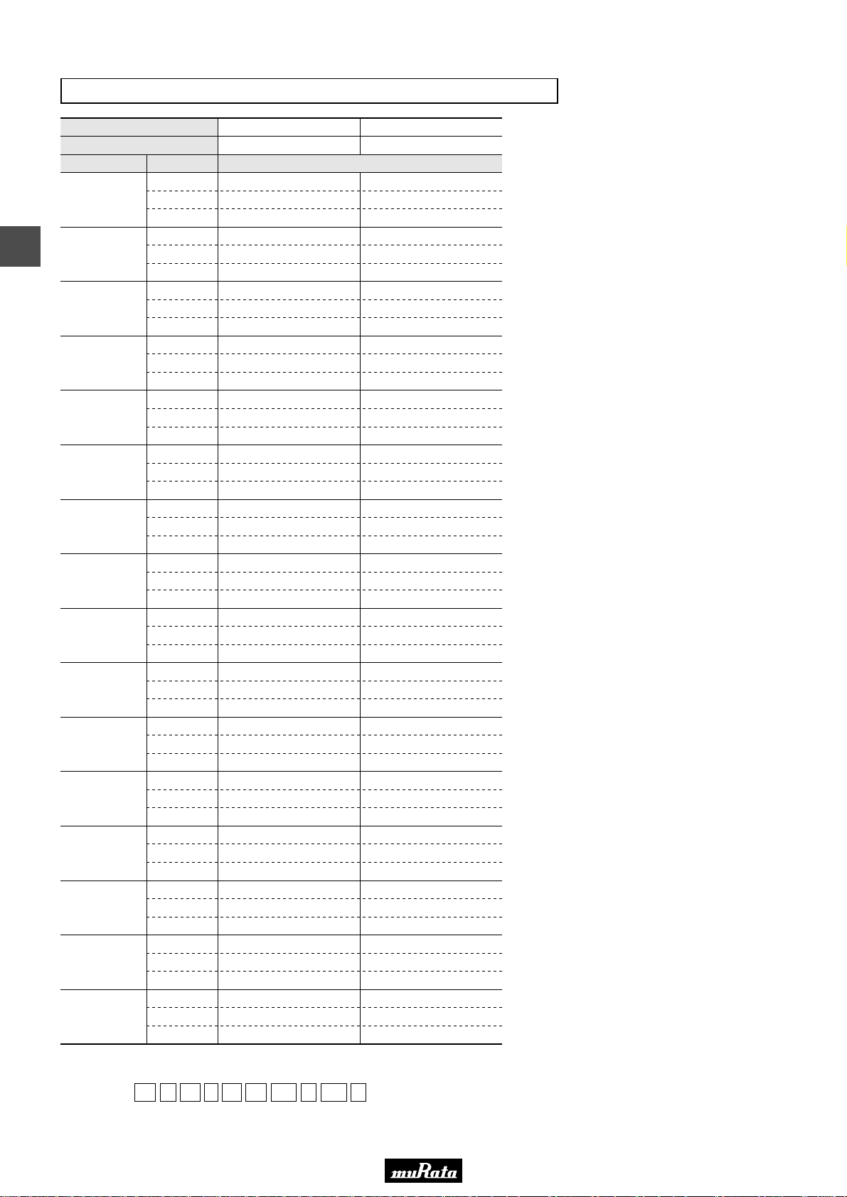
• This PDF catalog is downloaded from the website of Murata Manufacturing co., ltd. Therefore, it’s specifications are subject to change or our products in it may be discontinued without advance notice. Please check with our
!Note
• Please read rating and !CAUTION (for storage, operating, rating, soldering, mounting and handling) in this catalog to prevent smoking and/or burning, etc.
!Note
sales representatives or product engineers before ordering.
• This catalog has only typical specifications because there is no space for detailed specifications. Therefore, please approve our product specifications or transact the approval sheet for product specifications before ordering.
• This PDF catalog has only typical specifications because there is no space for detailed specifications. Therefore, please approve our product specifications or transact the approval sheet for product specifications before ordering.
Temperature Compensating Type C0G(5C) Characteristics
C02E.pdf
09.9.18
LxW [mm]
Rated Volt. [Vdc]
Capacitance Tolerance Part Number
2.1pF(2R1)
2.2pF(2R2)
4
2.3pF(2R3)
2.4pF(2R4)
2.5pF(2R5)
2.6pF(2R6)
2.7pF(2R7)
2.8pF(2R8)
2.9pF(2R9)
3.0pF(3R0)
3.1pF(3R1)
3.2pF(3R2)
3.3pF(3R3)
3.4pF(3R4)
3.5pF(3R5)
3.6pF(3R6)
The part number code is shown in ( ) and Unit is shown in [ ]. < >: EIA [inch] Code
±0.05pF(W)
±0.1pF(B)
±0.25pF(C)
±0.05pF(W)
±0.1pF(B)
±0.25pF(C)
±0.05pF(W)
±0.1pF(B)
±0.25pF(C)
±0.05pF(W)
±0.1pF(B)
±0.25pF(C)
±0.05pF(W)
±0.1pF(B)
±0.25pF(C)
±0.05pF(W)
±0.1pF(B)
±0.25pF(C)
±0.05pF(W)
±0.1pF(B)
±0.25pF(C)
±0.05pF(W)
±0.1pF(B)
±0.25pF(C)
±0.05pF(W)
±0.1pF(B)
±0.25pF(C)
±0.05pF(W)
±0.1pF(B)
±0.25pF(C)
±0.05pF(W)
±0.1pF(B)
±0.25pF(C)
±0.05pF(W)
±0.1pF(B)
±0.25pF(C)
±0.05pF(W)
±0.1pF(B)
±0.25pF(C)
±0.05pF(W)
±0.1pF(B)
±0.25pF(C)
±0.05pF(W)
±0.1pF(B)
±0.25pF(C)
±0.05pF(W)
±0.1pF(B)
±0.25pF(C)
0.6x0.3(03)<0201> 1.0x0.5(15)<0402>
25(1E)
GJM0335C1E2R1WB01D
GJM0335C1E2R1BB01D
GJM0335C1E2R1CB01D
GJM0335C1E2R2WB01D
GJM0335C1E2R2BB01D
GJM0335C1E2R2CB01D
GJM0335C1E2R3WB01D
GJM0335C1E2R3BB01D
GJM0335C1E2R3CB01D
GJM0335C1E2R4WB01D
GJM0335C1E2R4BB01D
GJM0335C1E2R4CB01D
GJM0335C1E2R5WB01D
GJM0335C1E2R5BB01D
GJM0335C1E2R5CB01D
GJM0335C1E2R6WB01D
GJM0335C1E2R6BB01D
GJM0335C1E2R6CB01D
GJM0335C1E2R7WB01D
GJM0335C1E2R7BB01D
GJM0335C1E2R7CB01D
GJM0335C1E2R8WB01D
GJM0335C1E2R8BB01D
GJM0335C1E2R8CB01D
GJM0335C1E2R9WB01D
GJM0335C1E2R9BB01D
GJM0335C1E2R9CB01D
GJM0335C1E3R0WB01D
GJM0335C1E3R0BB01D
GJM0335C1E3R0CB01D
GJM0335C1E3R1WB01D
GJM0335C1E3R1BB01D
GJM0335C1E3R1CB01D
GJM0335C1E3R2WB01D
GJM0335C1E3R2BB01D
GJM0335C1E3R2CB01D
GJM0335C1E3R3WB01D
GJM0335C1E3R3BB01D
GJM0335C1E3R3CB01D
GJM0335C1E3R4WB01D
GJM0335C1E3R4BB01D
GJM0335C1E3R4CB01D
GJM0335C1E3R5WB01D
GJM0335C1E3R5BB01D
GJM0335C1E3R5CB01D
GJM0335C1E3R6WB01D
GJM0335C1E3R6BB01D
GJM0335C1E3R6CB01D
GJM1555C1H2R1WB01D
GJM1555C1H2R1BB01D
GJM1555C1H2R1CB01D
GJM1555C1H2R2WB01D
GJM1555C1H2R2BB01D
GJM1555C1H2R2CB01D
GJM1555C1H2R3WB01D
GJM1555C1H2R3BB01D
GJM1555C1H2R3CB01D
GJM1555C1H2R4WB01D
GJM1555C1H2R4BB01D
GJM1555C1H2R4CB01D
GJM1555C1H2R5WB01D
GJM1555C1H2R5BB01D
GJM1555C1H2R5CB01D
GJM1555C1H2R6WB01D
GJM1555C1H2R6BB01D
GJM1555C1H2R6CB01D
GJM1555C1H2R7WB01D
GJM1555C1H2R7BB01D
GJM1555C1H2R7CB01D
GJM1555C1H2R8WB01D
GJM1555C1H2R8BB01D
GJM1555C1H2R8CB01D
GJM1555C1H2R9WB01D
GJM1555C1H2R9BB01D
GJM1555C1H2R9CB01D
GJM1555C1H3R0WB01D
GJM1555C1H3R0BB01D
GJM1555C1H3R0CB01D
GJM1555C1H3R1WB01D
GJM1555C1H3R1BB01D
GJM1555C1H3R1CB01D
GJM1555C1H3R2WB01D
GJM1555C1H3R2BB01D
GJM1555C1H3R2CB01D
GJM1555C1H3R3WB01D
GJM1555C1H3R3BB01D
GJM1555C1H3R3CB01D
GJM1555C1H3R4WB01D
GJM1555C1H3R4BB01D
GJM1555C1H3R4CB01D
GJM1555C1H3R5WB01D
GJM1555C1H3R5BB01D
GJM1555C1H3R5CB01D
GJM1555C1H3R6WB01D
GJM1555C1H3R6BB01D
GJM1555C1H3R6CB01D
50(1H)
(Part Number)
Packaging Code in Part Number is a code shows STD 180mm Reel Taping.
GJ M 03 3 5C 1E 2R1 W B01 D
e r t y u i o !0
wq
qProduct ID wSeries eDimension (LxW) rDimension (T)
tTemperature Characteristics yRated Voltage uCapacitance
iCapacitance Tolerance oIndividual Specification Code !0Packaging
88
Page 91
• This PDF catalog is downloaded from the website of Murata Manufacturing co., ltd. Therefore, it’s specifications are subject to change or our products in it may be discontinued without advance notice. Please check with our
!Note
• Please read rating and !CAUTION (for storage, operating, rating, soldering, mounting and handling) in this catalog to prevent smoking and/or burning, etc.
!Note
sales representatives or product engineers before ordering.
• This catalog has only typical specifications because there is no space for detailed specifications. Therefore, please approve our product specifications or transact the approval sheet for product specifications before ordering.
• This PDF catalog has only typical specifications because there is no space for detailed specifications. Therefore, please approve our product specifications or transact the approval sheet for product specifications before ordering.
Temperature Compensating Type C0G(5C) Characteristics
C02E.pdf
09.9.18
LxW [mm]
Rated Volt. [Vdc]
Capacitance Tolerance Part Number
3.7pF(3R7)
3.8pF(3R8)
3.9pF(3R9)
4.0pF(4R0)
4.1pF(4R1)
4.2pF(4R2)
4.3pF(4R3)
4.4pF(4R4)
4.5pF(4R5)
4.6pF(4R6)
4.7pF(4R7)
4.8pF(4R8)
4.9pF(4R9)
5.0pF(5R0)
5.1pF(5R1)
5.2pF(5R2)
The part number code is shown in ( ) and Unit is shown in [ ]. < >: EIA [inch] Code
±0.05pF(W)
±0.1pF(B)
±0.25pF(C)
±0.05pF(W)
±0.1pF(B)
±0.25pF(C)
±0.05pF(W)
±0.1pF(B)
±0.25pF(C)
±0.05pF(W)
±0.1pF(B)
±0.25pF(C)
±0.05pF(W)
±0.1pF(B)
±0.25pF(C)
±0.05pF(W)
±0.1pF(B)
±0.25pF(C)
±0.05pF(W)
±0.1pF(B)
±0.25pF(C)
±0.05pF(W)
±0.1pF(B)
±0.25pF(C)
±0.05pF(W)
±0.1pF(B)
±0.25pF(C)
±0.05pF(W)
±0.1pF(B)
±0.25pF(C)
±0.05pF(W)
±0.1pF(B)
±0.25pF(C)
±0.05pF(W)
±0.1pF(B)
±0.25pF(C)
±0.05pF(W)
±0.1pF(B)
±0.25pF(C)
±0.05pF(W)
±0.1pF(B)
±0.25pF(C)
±0.05pF(W)
±0.1pF(B)
±0.25pF(C)
±0.5pF(D)
±0.05pF(W)
±0.1pF(B)
±0.25pF(C)
±0.5pF(D)
0.6x0.3(03)<0201> 1.0x0.5(15)<0402>
25(1E)
GJM0335C1E3R7WB01D
GJM0335C1E3R7BB01D
GJM0335C1E3R7CB01D
GJM0335C1E3R8WB01D
GJM0335C1E3R8BB01D
GJM0335C1E3R8CB01D
GJM0335C1E3R9WB01D
GJM0335C1E3R9BB01D
GJM0335C1E3R9CB01D
GJM0335C1E4R0WB01D
GJM0335C1E4R0BB01D
GJM0335C1E4R0CB01D
GJM0335C1E4R1WB01D
GJM0335C1E4R1BB01D
GJM0335C1E4R1CB01D
GJM0335C1E4R2WB01D
GJM0335C1E4R2BB01D
GJM0335C1E4R2CB01D
GJM0335C1E4R3WB01D
GJM0335C1E4R3BB01D
GJM0335C1E4R3CB01D
GJM0335C1E4R4WB01D
GJM0335C1E4R4BB01D
GJM0335C1E4R4CB01D
GJM0335C1E4R5WB01D
GJM0335C1E4R5BB01D
GJM0335C1E4R5CB01D
GJM0335C1E4R6WB01D
GJM0335C1E4R6BB01D
GJM0335C1E4R6CB01D
GJM0335C1E4R7WB01D
GJM0335C1E4R7BB01D
GJM0335C1E4R7CB01D
GJM0335C1E4R8WB01D
GJM0335C1E4R8BB01D
GJM0335C1E4R8CB01D
GJM0335C1E4R9WB01D
GJM0335C1E4R9BB01D
GJM0335C1E4R9CB01D
GJM0335C1E5R0WB01D
GJM0335C1E5R0BB01D
GJM0335C1E5R0CB01D
GJM0335C1E5R1WB01D
GJM0335C1E5R1BB01D
GJM0335C1E5R1CB01D
GJM0335C1E5R1DB01D
GJM0335C1E5R2WB01D
GJM0335C1E5R2BB01D
GJM0335C1E5R2CB01D
GJM0335C1E5R2DB01D
GJM1555C1H3R7WB01D
GJM1555C1H3R7BB01D
GJM1555C1H3R7CB01D
GJM1555C1H3R8WB01D
GJM1555C1H3R8BB01D
GJM1555C1H3R8CB01D
GJM1555C1H3R9WB01D
GJM1555C1H3R9BB01D
GJM1555C1H3R9CB01D
GJM1555C1H4R0WB01D
GJM1555C1H4R0BB01D
GJM1555C1H4R0CB01D
GJM1555C1H4R1WB01D
GJM1555C1H4R1BB01D
GJM1555C1H4R1CB01D
GJM1555C1H4R2WB01D
GJM1555C1H4R2BB01D
GJM1555C1H4R2CB01D
GJM1555C1H4R3WB01D
GJM1555C1H4R3BB01D
GJM1555C1H4R3CB01D
GJM1555C1H4R4WB01D
GJM1555C1H4R4BB01D
GJM1555C1H4R4CB01D
GJM1555C1H4R5WB01D
GJM1555C1H4R5BB01D
GJM1555C1H4R5CB01D
GJM1555C1H4R6WB01D
GJM1555C1H4R6BB01D
GJM1555C1H4R6CB01D
GJM1555C1H4R7WB01D
GJM1555C1H4R7BB01D
GJM1555C1H4R7CB01D
GJM1555C1H4R8WB01D
GJM1555C1H4R8BB01D
GJM1555C1H4R8CB01D
GJM1555C1H4R9WB01D
GJM1555C1H4R9BB01D
GJM1555C1H4R9CB01D
GJM1555C1H5R0WB01D
GJM1555C1H5R0BB01D
GJM1555C1H5R0CB01D
GJM1555C1H5R1WB01D
GJM1555C1H5R1BB01D
GJM1555C1H5R1CB01D
GJM1555C1H5R1DB01D
GJM1555C1H5R2WB01D
GJM1555C1H5R2BB01D
GJM1555C1H5R2CB01D
GJM1555C1H5R2DB01D
50(1H)
4
89
Page 92

• This PDF catalog is downloaded from the website of Murata Manufacturing co., ltd. Therefore, it’s specifications are subject to change or our products in it may be discontinued without advance notice. Please check with our
!Note
• Please read rating and !CAUTION (for storage, operating, rating, soldering, mounting and handling) in this catalog to prevent smoking and/or burning, etc.
!Note
sales representatives or product engineers before ordering.
• This catalog has only typical specifications because there is no space for detailed specifications. Therefore, please approve our product specifications or transact the approval sheet for product specifications before ordering.
• This PDF catalog has only typical specifications because there is no space for detailed specifications. Therefore, please approve our product specifications or transact the approval sheet for product specifications before ordering.
Temperature Compensating Type C0G(5C) Characteristics
C02E.pdf
09.9.18
LxW [mm]
Rated Volt. [Vdc]
Capacitance Tolerance Part Number
5.3pF(5R3)
4
5.4pF(5R4)
5.5pF(5R5)
5.6pF(5R6)
5.7pF(5R7)
5.8pF(5R8)
5.9pF(5R9)
6.0pF(6R0)
6.1pF(6R1)
6.2pF(6R2)
6.3pF(6R3)
6.4pF(6R4)
The part number code is shown in ( ) and Unit is shown in [ ]. < >: EIA [inch] Code
±0.05pF(W)
±0.1pF(B)
±0.25pF(C)
±0.5pF(D)
±0.05pF(W)
±0.1pF(B)
±0.25pF(C)
±0.5pF(D)
±0.05pF(W)
±0.1pF(B)
±0.25pF(C)
±0.5pF(D)
±0.05pF(W)
±0.1pF(B)
±0.25pF(C)
±0.5pF(D)
±0.05pF(W)
±0.1pF(B)
±0.25pF(C)
±0.5pF(D)
±0.05pF(W)
±0.1pF(B)
±0.25pF(C)
±0.5pF(D)
±0.05pF(W)
±0.1pF(B)
±0.25pF(C)
±0.5pF(D)
±0.05pF(W)
±0.1pF(B)
±0.25pF(C)
±0.5pF(D)
±0.05pF(W)
±0.1pF(B)
±0.25pF(C)
±0.5pF(D)
±0.05pF(W)
±0.1pF(B)
±0.25pF(C)
±0.5pF(D)
±0.05pF(W)
±0.1pF(B)
±0.25pF(C)
±0.5pF(D)
±0.05pF(W)
±0.1pF(B)
±0.25pF(C)
±0.5pF(D)
0.6x0.3(03)<0201> 1.0x0.5(15)<0402>
25(1E)
GJM0335C1E5R3WB01D
GJM0335C1E5R3BB01D
GJM0335C1E5R3CB01D
GJM0335C1E5R3DB01D
GJM0335C1E5R4WB01D
GJM0335C1E5R4BB01D
GJM0335C1E5R4CB01D
GJM0335C1E5R4DB01D
GJM0335C1E5R5WB01D
GJM0335C1E5R5BB01D
GJM0335C1E5R5CB01D
GJM0335C1E5R5DB01D
GJM0335C1E5R6WB01D
GJM0335C1E5R6BB01D
GJM0335C1E5R6CB01D
GJM0335C1E5R6DB01D
GJM0335C1E5R7WB01D
GJM0335C1E5R7BB01D
GJM0335C1E5R7CB01D
GJM0335C1E5R7DB01D
GJM0335C1E5R8WB01D
GJM0335C1E5R8BB01D
GJM0335C1E5R8CB01D
GJM0335C1E5R8DB01D
GJM0335C1E5R9WB01D
GJM0335C1E5R9BB01D
GJM0335C1E5R9CB01D
GJM0335C1E5R9DB01D
GJM0335C1E6R0WB01D
GJM0335C1E6R0BB01D
GJM0335C1E6R0CB01D
GJM0335C1E6R0DB01D
GJM0335C1E6R1WB01D
GJM0335C1E6R1BB01D
GJM0335C1E6R1CB01D
GJM0335C1E6R1DB01D
GJM0335C1E6R2WB01D
GJM0335C1E6R2BB01D
GJM0335C1E6R2CB01D
GJM0335C1E6R2DB01D
GJM0335C1E6R3WB01D
GJM0335C1E6R3BB01D
GJM0335C1E6R3CB01D
GJM0335C1E6R3DB01D
GJM0335C1E6R4WB01D
GJM0335C1E6R4BB01D
GJM0335C1E6R4CB01D
GJM0335C1E6R4DB01D
GJM1555C1H5R3WB01D
GJM1555C1H5R3BB01D
GJM1555C1H5R3CB01D
GJM1555C1H5R3DB01D
GJM1555C1H5R4WB01D
GJM1555C1H5R4BB01D
GJM1555C1H5R4CB01D
GJM1555C1H5R4DB01D
GJM1555C1H5R5WB01D
GJM1555C1H5R5BB01D
GJM1555C1H5R5CB01D
GJM1555C1H5R5DB01D
GJM1555C1H5R6WB01D
GJM1555C1H5R6BB01D
GJM1555C1H5R6CB01D
GJM1555C1H5R6DB01D
GJM1555C1H5R7WB01D
GJM1555C1H5R7BB01D
GJM1555C1H5R7CB01D
GJM1555C1H5R7DB01D
GJM1555C1H5R8WB01D
GJM1555C1H5R8BB01D
GJM1555C1H5R8CB01D
GJM1555C1H5R8DB01D
GJM1555C1H5R9WB01D
GJM1555C1H5R9BB01D
GJM1555C1H5R9CB01D
GJM1555C1H5R9DB01D
GJM1555C1H6R0WB01D
GJM1555C1H6R0BB01D
GJM1555C1H6R0CB01D
GJM1555C1H6R0DB01D
GJM1555C1H6R1WB01D
GJM1555C1H6R1BB01D
GJM1555C1H6R1CB01D
GJM1555C1H6R1DB01D
GJM1555C1H6R2WB01D
GJM1555C1H6R2BB01D
GJM1555C1H6R2CB01D
GJM1555C1H6R2DB01D
GJM1555C1H6R3WB01D
GJM1555C1H6R3BB01D
GJM1555C1H6R3CB01D
GJM1555C1H6R3DB01D
GJM1555C1H6R4WB01D
GJM1555C1H6R4BB01D
GJM1555C1H6R4CB01D
GJM1555C1H6R4DB01D
50(1H)
(Part Number)
Packaging Code in Part Number is a code shows STD 180mm Reel Taping.
GJ M 03 3 5C 1E 5R3 W B01 D
e r t y u i o !0
wq
qProduct ID wSeries eDimension (LxW) rDimension (T)
tTemperature Characteristics yRated Voltage uCapacitance
iCapacitance Tolerance oIndividual Specification Code !0Packaging
90
Page 93
• This PDF catalog is downloaded from the website of Murata Manufacturing co., ltd. Therefore, it’s specifications are subject to change or our products in it may be discontinued without advance notice. Please check with our
!Note
• Please read rating and !CAUTION (for storage, operating, rating, soldering, mounting and handling) in this catalog to prevent smoking and/or burning, etc.
!Note
sales representatives or product engineers before ordering.
• This catalog has only typical specifications because there is no space for detailed specifications. Therefore, please approve our product specifications or transact the approval sheet for product specifications before ordering.
• This PDF catalog has only typical specifications because there is no space for detailed specifications. Therefore, please approve our product specifications or transact the approval sheet for product specifications before ordering.
Temperature Compensating Type C0G(5C)/C0H(6C) Characteristics
C02E.pdf
09.9.18
LxW [mm]
Rated Volt. [Vdc]
Capacitance Tolerance Part Number
6.5pF(6R5)
6.6pF(6R6)
6.7pF(6R7)
6.8pF(6R8)
6.9pF(6R9)
7.0pF(7R0)
7.1pF(7R1)
7.2pF(7R2)
7.3pF(7R3)
7.4pF(7R4)
7.5pF(7R5)
7.6pF(7R6)
7.7pF(7R7)
The part number code is shown in ( ) and Unit is shown in [ ]. < >: EIA [inch] Code
±0.05pF(W)
±0.1pF(B)
±0.25pF(C)
±0.5pF(D)
±0.05pF(W)
±0.1pF(B)
±0.25pF(C)
±0.5pF(D)
±0.05pF(W)
±0.1pF(B)
±0.25pF(C)
±0.5pF(D)
±0.05pF(W)
±0.1pF(B)
±0.25pF(C)
±0.5pF(D)
±0.05pF(W)
±0.1pF(B)
±0.25pF(C)
±0.5pF(D)
±0.05pF(W)
±0.1pF(B)
±0.25pF(C)
±0.5pF(D)
±0.05pF(W)
±0.1pF(B)
±0.25pF(C)
±0.5pF(D)
±0.05pF(W)
±0.1pF(B)
±0.25pF(C)
±0.5pF(D)
±0.05pF(W)
±0.1pF(B)
±0.25pF(C)
±0.5pF(D)
±0.05pF(W)
±0.1pF(B)
±0.25pF(C)
±0.5pF(D)
±0.05pF(W)
±0.1pF(B)
±0.25pF(C)
±0.5pF(D)
±0.05pF(W)
±0.1pF(B)
±0.25pF(C)
±0.5pF(D)
±0.05pF(W)
±0.1pF(B)
±0.25pF(C)
±0.5pF(D)
0.6x0.3(03)<0201> 1.0x0.5(15)<0402>
25(1E)
GJM0335C1E6R5WB01D
GJM0335C1E6R5BB01D
GJM0335C1E6R5CB01D
GJM0335C1E6R5DB01D
GJM0335C1E6R6WB01D
GJM0335C1E6R6BB01D
GJM0335C1E6R6CB01D
GJM0335C1E6R6DB01D
GJM0335C1E6R7WB01D
GJM0335C1E6R7BB01D
GJM0335C1E6R7CB01D
GJM0335C1E6R7DB01D
GJM0335C1E6R8WB01D
GJM0335C1E6R8BB01D
GJM0335C1E6R8CB01D
GJM0335C1E6R8DB01D
GJM0336C1E6R9WB01D
GJM0336C1E6R9BB01D
GJM0336C1E6R9CB01D
GJM0336C1E6R9DB01D
GJM0336C1E7R0WB01D
GJM0336C1E7R0BB01D
GJM0336C1E7R0CB01D
GJM0336C1E7R0DB01D
GJM0336C1E7R1WB01D
GJM0336C1E7R1BB01D
GJM0336C1E7R1CB01D
GJM0336C1E7R1DB01D
GJM0336C1E7R2WB01D
GJM0336C1E7R2BB01D
GJM0336C1E7R2CB01D
GJM0336C1E7R2DB01D
GJM0336C1E7R3WB01D
GJM0336C1E7R3BB01D
GJM0336C1E7R3CB01D
GJM0336C1E7R3DB01D
GJM0336C1E7R4WB01D
GJM0336C1E7R4BB01D
GJM0336C1E7R4CB01D
GJM0336C1E7R4DB01D
GJM0336C1E7R5WB01D
GJM0336C1E7R5BB01D
GJM0336C1E7R5CB01D
GJM0336C1E7R5DB01D
GJM0336C1E7R6WB01D
GJM0336C1E7R6BB01D
GJM0336C1E7R6CB01D
GJM0336C1E7R6DB01D
GJM0336C1E7R7WB01D
GJM0336C1E7R7BB01D
GJM0336C1E7R7CB01D
GJM0336C1E7R7DB01D
GJM1555C1H6R5WB01D
GJM1555C1H6R5BB01D
GJM1555C1H6R5CB01D
GJM1555C1H6R5DB01D
GJM1555C1H6R6WB01D
GJM1555C1H6R6BB01D
GJM1555C1H6R6CB01D
GJM1555C1H6R6DB01D
GJM1555C1H6R7WB01D
GJM1555C1H6R7BB01D
GJM1555C1H6R7CB01D
GJM1555C1H6R7DB01D
GJM1555C1H6R8WB01D
GJM1555C1H6R8BB01D
GJM1555C1H6R8CB01D
GJM1555C1H6R8DB01D
GJM1555C1H6R9WB01D
GJM1555C1H6R9BB01D
GJM1555C1H6R9CB01D
GJM1555C1H6R9DB01D
GJM1555C1H7R0WB01D
GJM1555C1H7R0BB01D
GJM1555C1H7R0CB01D
GJM1555C1H7R0DB01D
GJM1555C1H7R1WB01D
GJM1555C1H7R1BB01D
GJM1555C1H7R1CB01D
GJM1555C1H7R1DB01D
GJM1555C1H7R2WB01D
GJM1555C1H7R2BB01D
GJM1555C1H7R2CB01D
GJM1555C1H7R2DB01D
GJM1555C1H7R3WB01D
GJM1555C1H7R3BB01D
GJM1555C1H7R3CB01D
GJM1555C1H7R3DB01D
GJM1555C1H7R4WB01D
GJM1555C1H7R4BB01D
GJM1555C1H7R4CB01D
GJM1555C1H7R4DB01D
GJM1555C1H7R5WB01D
GJM1555C1H7R5BB01D
GJM1555C1H7R5CB01D
GJM1555C1H7R5DB01D
GJM1555C1H7R6WB01D
GJM1555C1H7R6BB01D
GJM1555C1H7R6CB01D
GJM1555C1H7R6DB01D
GJM1555C1H7R7WB01D
GJM1555C1H7R7BB01D
GJM1555C1H7R7CB01D
GJM1555C1H7R7DB01D
50(1H)
4
91
Page 94

• This PDF catalog is downloaded from the website of Murata Manufacturing co., ltd. Therefore, it’s specifications are subject to change or our products in it may be discontinued without advance notice. Please check with our
!Note
• Please read rating and !CAUTION (for storage, operating, rating, soldering, mounting and handling) in this catalog to prevent smoking and/or burning, etc.
!Note
sales representatives or product engineers before ordering.
• This catalog has only typical specifications because there is no space for detailed specifications. Therefore, please approve our product specifications or transact the approval sheet for product specifications before ordering.
• This PDF catalog has only typical specifications because there is no space for detailed specifications. Therefore, please approve our product specifications or transact the approval sheet for product specifications before ordering.
Temperature Compensating Type C0G(5C)/C0H(6C) Characteristics
C02E.pdf
09.9.18
LxW [mm]
Rated Volt. [Vdc]
Capacitance Tolerance Part Number
7.8pF(7R8)
4
7.9pF(7R9)
8.0pF(8R0)
8.1pF(8R1)
8.2pF(8R2)
8.3pF(8R3)
8.4pF(8R4)
8.5pF(8R5)
8.6pF(8R6)
8.7pF(8R7)
8.8pF(8R8)
8.9pF(8R9)
The part number code is shown in ( ) and Unit is shown in [ ]. < >: EIA [inch] Code
±0.05pF(W)
±0.1pF(B)
±0.25pF(C)
±0.5pF(D)
±0.05pF(W)
±0.1pF(B)
±0.25pF(C)
±0.5pF(D)
±0.05pF(W)
±0.1pF(B)
±0.25pF(C)
±0.5pF(D)
±0.05pF(W)
±0.1pF(B)
±0.25pF(C)
±0.5pF(D)
±0.05pF(W)
±0.1pF(B)
±0.25pF(C)
±0.5pF(D)
±0.05pF(W)
±0.1pF(B)
±0.25pF(C)
±0.5pF(D)
±0.05pF(W)
±0.1pF(B)
±0.25pF(C)
±0.5pF(D)
±0.05pF(W)
±0.1pF(B)
±0.25pF(C)
±0.5pF(D)
±0.05pF(W)
±0.1pF(B)
±0.25pF(C)
±0.5pF(D)
±0.05pF(W)
±0.1pF(B)
±0.25pF(C)
±0.5pF(D)
±0.05pF(W)
±0.1pF(B)
±0.25pF(C)
±0.5pF(D)
±0.05pF(W)
±0.1pF(B)
±0.25pF(C)
±0.5pF(D)
0.6x0.3(03)<0201> 1.0x0.5(15)<0402>
25(1E)
GJM0336C1E7R8WB01D
GJM0336C1E7R8BB01D
GJM0336C1E7R8CB01D
GJM0336C1E7R8DB01D
GJM0336C1E7R9WB01D
GJM0336C1E7R9BB01D
GJM0336C1E7R9CB01D
GJM0336C1E7R9DB01D
GJM0336C1E8R0WB01D
GJM0336C1E8R0BB01D
GJM0336C1E8R0CB01D
GJM0336C1E8R0DB01D
GJM0336C1E8R1WB01D
GJM0336C1E8R1BB01D
GJM0336C1E8R1CB01D
GJM0336C1E8R1DB01D
GJM0336C1E8R2WB01D
GJM0336C1E8R2BB01D
GJM0336C1E8R2CB01D
GJM0336C1E8R2DB01D
GJM0336C1E8R3WB01D
GJM0336C1E8R3BB01D
GJM0336C1E8R3CB01D
GJM0336C1E8R3DB01D
GJM0336C1E8R4WB01D
GJM0336C1E8R4BB01D
GJM0336C1E8R4CB01D
GJM0336C1E8R4DB01D
GJM0336C1E8R5WB01D
GJM0336C1E8R5BB01D
GJM0336C1E8R5CB01D
GJM0336C1E8R5DB01D
GJM0336C1E8R6WB01D
GJM0336C1E8R6BB01D
GJM0336C1E8R6CB01D
GJM0336C1E8R6DB01D
GJM0336C1E8R7WB01D
GJM0336C1E8R7BB01D
GJM0336C1E8R7CB01D
GJM0336C1E8R7DB01D
GJM0336C1E8R8WB01D
GJM0336C1E8R8BB01D
GJM0336C1E8R8CB01D
GJM0336C1E8R8DB01D
GJM0336C1E8R9WB01D
GJM0336C1E8R9BB01D
GJM0336C1E8R9CB01D
GJM0336C1E8R9DB01D
GJM1555C1H7R8WB01D
GJM1555C1H7R8BB01D
GJM1555C1H7R8CB01D
GJM1555C1H7R8DB01D
GJM1555C1H7R9WB01D
GJM1555C1H7R9BB01D
GJM1555C1H7R9CB01D
GJM1555C1H7R9DB01D
GJM1555C1H8R0WB01D
GJM1555C1H8R0BB01D
GJM1555C1H8R0CB01D
GJM1555C1H8R0DB01D
GJM1555C1H8R1WB01D
GJM1555C1H8R1BB01D
GJM1555C1H8R1CB01D
GJM1555C1H8R1DB01D
GJM1555C1H8R2WB01D
GJM1555C1H8R2BB01D
GJM1555C1H8R2CB01D
GJM1555C1H8R2DB01D
GJM1555C1H8R3WB01D
GJM1555C1H8R3BB01D
GJM1555C1H8R3CB01D
GJM1555C1H8R3DB01D
GJM1555C1H8R4WB01D
GJM1555C1H8R4BB01D
GJM1555C1H8R4CB01D
GJM1555C1H8R4DB01D
GJM1555C1H8R5WB01D
GJM1555C1H8R5BB01D
GJM1555C1H8R5CB01D
GJM1555C1H8R5DB01D
GJM1555C1H8R6WB01D
GJM1555C1H8R6BB01D
GJM1555C1H8R6CB01D
GJM1555C1H8R6DB01D
GJM1555C1H8R7WB01D
GJM1555C1H8R7BB01D
GJM1555C1H8R7CB01D
GJM1555C1H8R7DB01D
GJM1555C1H8R8WB01D
GJM1555C1H8R8BB01D
GJM1555C1H8R8CB01D
GJM1555C1H8R8DB01D
GJM1555C1H8R9WB01D
GJM1555C1H8R9BB01D
GJM1555C1H8R9CB01D
GJM1555C1H8R9DB01D
50(1H)
(Part Number)
Packaging Code in Part Number is a code shows STD 180mm Reel Taping.
GJ M 03 3 6C 1E 7R8 W B01 D
e r t y u i o !0
wq
qProduct ID wSeries eDimension (LxW) rDimension (T)
tTemperature Characteristics yRated Voltage uCapacitance
iCapacitance Tolerance oIndividual Specification Code !0Packaging
92
Page 95

• This PDF catalog is downloaded from the website of Murata Manufacturing co., ltd. Therefore, it’s specifications are subject to change or our products in it may be discontinued without advance notice. Please check with our
!Note
• Please read rating and !CAUTION (for storage, operating, rating, soldering, mounting and handling) in this catalog to prevent smoking and/or burning, etc.
!Note
sales representatives or product engineers before ordering.
• This catalog has only typical specifications because there is no space for detailed specifications. Therefore, please approve our product specifications or transact the approval sheet for product specifications before ordering.
• This PDF catalog has only typical specifications because there is no space for detailed specifications. Therefore, please approve our product specifications or transact the approval sheet for product specifications before ordering.
Temperature Compensating Type C0G(5C)/C0H(6C) Characteristics
C02E.pdf
09.9.18
LxW [mm]
Rated Volt. [Vdc]
Capacitance Tolerance Part Number
9.0pF(9R0)
9.1pF(9R1)
9.2pF(9R2)
9.3pF(9R3)
9.4pF(9R4)
9.5pF(9R5)
9.6pF(9R6)
9.7pF(9R7)
9.8pF(9R8)
9.9pF(9R9)
The part number code is shown in ( ) and Unit is shown in [ ]. < >: EIA [inch] Code
±0.05pF(W)
±0.1pF(B)
±0.25pF(C)
±0.5pF(D)
±0.05pF(W)
±0.1pF(B)
±0.25pF(C)
±0.5pF(D)
±0.05pF(W)
±0.1pF(B)
±0.25pF(C)
±0.5pF(D)
±0.05pF(W)
±0.1pF(B)
±0.25pF(C)
±0.5pF(D)
±0.05pF(W)
±0.1pF(B)
±0.25pF(C)
±0.5pF(D)
±0.05pF(W)
±0.1pF(B)
±0.25pF(C)
±0.5pF(D)
±0.05pF(W)
±0.1pF(B)
±0.25pF(C)
±0.5pF(D)
±0.05pF(W)
±0.1pF(B)
±0.25pF(C)
±0.5pF(D)
±0.05pF(W)
±0.1pF(B)
±0.25pF(C)
±0.5pF(D)
±0.05pF(W)
±0.1pF(B)
±0.25pF(C)
±0.5pF(D)
GJM0336C1E9R0WB01D
GJM0336C1E9R0BB01D
GJM0336C1E9R0CB01D
GJM0336C1E9R0DB01D
GJM0336C1E9R1WB01D
GJM0336C1E9R1BB01D
GJM0336C1E9R1CB01D
GJM0336C1E9R1DB01D
GJM0336C1E9R2WB01D
GJM0336C1E9R2BB01D
GJM0336C1E9R2CB01D
GJM0336C1E9R2DB01D
GJM0336C1E9R3WB01D
GJM0336C1E9R3BB01D
GJM0336C1E9R3CB01D
GJM0336C1E9R3DB01D
GJM0336C1E9R4WB01D
GJM0336C1E9R4BB01D
GJM0336C1E9R4CB01D
GJM0336C1E9R4DB01D
GJM0336C1E9R5WB01D
GJM0336C1E9R5BB01D
GJM0336C1E9R5CB01D
GJM0336C1E9R5DB01D
GJM0336C1E9R6WB01D
GJM0336C1E9R6BB01D
GJM0336C1E9R6CB01D
GJM0336C1E9R6DB01D
GJM0336C1E9R7WB01D
GJM0336C1E9R7BB01D
GJM0336C1E9R7CB01D
GJM0336C1E9R7DB01D
GJM0336C1E9R8WB01D
GJM0336C1E9R8BB01D
GJM0336C1E9R8CB01D
GJM0336C1E9R8DB01D
GJM0336C1E9R9WB01D
GJM0336C1E9R9BB01D
GJM0336C1E9R9CB01D
GJM0336C1E9R9DB01D
25(1E)
1.0x0.5(15)<0402>0.6x0.3(03)<0201>
GJM1555C1H9R0WB01D
GJM1555C1H9R0BB01D
GJM1555C1H9R0CB01D
GJM1555C1H9R0DB01D
GJM1555C1H9R1WB01D
GJM1555C1H9R1BB01D
GJM1555C1H9R1CB01D
GJM1555C1H9R1DB01D
GJM1555C1H9R2WB01D
GJM1555C1H9R2BB01D
GJM1555C1H9R2CB01D
GJM1555C1H9R2DB01D
GJM1555C1H9R3WB01D
GJM1555C1H9R3BB01D
GJM1555C1H9R3CB01D
GJM1555C1H9R3DB01D
GJM1555C1H9R4WB01D
GJM1555C1H9R4BB01D
GJM1555C1H9R4CB01D
GJM1555C1H9R4DB01D
GJM1555C1H9R5WB01D
GJM1555C1H9R5BB01D
GJM1555C1H9R5CB01D
GJM1555C1H9R5DB01D
GJM1555C1H9R6WB01D
GJM1555C1H9R6BB01D
GJM1555C1H9R6CB01D
GJM1555C1H9R6DB01D
GJM1555C1H9R7WB01D
GJM1555C1H9R7BB01D
GJM1555C1H9R7CB01D
GJM1555C1H9R7DB01D
GJM1555C1H9R8WB01D
GJM1555C1H9R8BB01D
GJM1555C1H9R8CB01D
GJM1555C1H9R8DB01D
GJM1555C1H9R9WB01D
GJM1555C1H9R9BB01D
GJM1555C1H9R9CB01D
GJM1555C1H9R9DB01D
50(1H)
4
93
Page 96
• This PDF catalog is downloaded from the website of Murata Manufacturing co., ltd. Therefore, it’s specifications are subject to change or our products in it may be discontinued without advance notice. Please check with our
!Note
• Please read rating and !CAUTION (for storage, operating, rating, soldering, mounting and handling) in this catalog to prevent smoking and/or burning, etc.
!Note
sales representatives or product engineers before ordering.
• This catalog has only typical specifications because there is no space for detailed specifications. Therefore, please approve our product specifications or transact the approval sheet for product specifications before ordering.
• This PDF catalog has only typical specifications because there is no space for detailed specifications. Therefore, please approve our product specifications or transact the approval sheet for product specifications before ordering.
Temperature Compensating Type C0G(5C)/C0H(6C) Characteristics
C02E.pdf
09.9.18
LxW [mm]
Rated Volt. [Vdc]
Capacitance Tolerance Part Number
10pF(100)
11pF(110)
4
12pF(120)
13pF(130)
15pF(150)
16pF(160)
18pF(180)
20pF(200)
22pF(220)
24pF(240)
27pF(270)
30pF(300)
33pF(330)
The part number code is shown in ( ) and Unit is shown in [ ]. < >: EIA [inch] Code
±2%(G)
±5%(J)
±2%(G)
±5%(J)
±2%(G)
±5%(J)
±2%(G)
±5%(J)
±2%(G)
±5%(J)
±2%(G)
±5%(J)
±2%(G)
±5%(J)
±2%(G)
±5%(J)
±2%(G)
±5%(J)
±2%(G)
±5%(J)
±2%(G)
±5%(J)
±2%(G)
±5%(J)
±2%(G)
±5%(J)
GJM0336C1E100GB01D
GJM0336C1E100JB01D
GJM0336C1E110GB01D
GJM0336C1E110JB01D
GJM0336C1E120GB01D
GJM0336C1E120JB01D
GJM0336C1E130GB01D
GJM0336C1E130JB01D
GJM0336C1E150GB01D
GJM0336C1E150JB01D
GJM0336C1E160GB01D
GJM0336C1E160JB01D
GJM0336C1E180GB01D
GJM0336C1E180JB01D
GJM0336C1E200GB01D
GJM0336C1E200JB01D
0.6x0.3(03)<0201> 1.0x0.5(15)<0402>
25(1E)
6.3(0J)
GJM1555C1H100GB01D
GJM1555C1H100JB01D
GJM1555C1H110GB01D
GJM1555C1H110JB01D
GJM1555C1H120GB01D
GJM1555C1H120JB01D
GJM1555C1H130GB01D
GJM1555C1H130JB01D
GJM1555C1H150GB01D
GJM1555C1H150JB01D
GJM1555C1H160GB01D
GJM1555C1H160JB01D
GJM1555C1H180GB01D
GJM1555C1H180JB01D
GJM1555C1H200GB01D
GJM1555C1H200JB01D
GJM0335C0J220GB01D
GJM0335C0J220JB01D
GJM0335C0J240GB01D
GJM0335C0J240JB01D
GJM0335C0J270GB01D
GJM0335C0J270JB01D
GJM0335C0J300GB01D
GJM0335C0J300JB01D
GJM0335C0J330GB01D
GJM0335C0J330JB01D
50(1H)
(Part Number)
Packaging Code in Part Number is a code shows STD 180mm Reel Taping.
GJ M 03 3 6C 1E 100 G B01 D
e r t y u i o !0
wq
qProduct ID wSeries eDimension (LxW) rDimension (T)
tTemperature Characteristics yRated Voltage uCapacitance
iCapacitance Tolerance oIndividual Specification Code !0Packaging
94
Page 97

GJM Series Specifications and Test Methods (1)
Continued on the following page.
a
b
c
Baked electrode or
copper foil
Solder resist
• This PDF catalog is downloaded from the website of Murata Manufacturing co., ltd. Therefore, it’s specifications are subject to change or our products in it may be discontinued without advance notice. Please check with our
!Note
• Please read rating and !CAUTION (for storage, operating, rating, soldering, mounting and handling) in this catalog to prevent smoking and/or burning, etc.
!Note
sales representatives or product engineers before ordering.
• This catalog has only typical specifications because there is no space for detailed specifications. Therefore, please approve our product specifications or transact the approval sheet for product specifications before ordering.
• This PDF catalog has only typical specifications because there is no space for detailed specifications. Therefore, please approve our product specifications or transact the approval sheet for product specifications before ordering.
C02E.pdf
09.9.18
GJM Series Specifications and Test Methods
Specifications
No. Item
Temperature Compensating Type
Operating
1
Temperature Range
2
Rated Voltage
3
Appearance
4
Dimensions
5
Dielectric Strength
Insulation Resistance
6
(I.R.)
Capacitance
Y55 to W125D
See the previous pages.
No defects or abnormalities
Within the specified dimensions
No defects or abnormalities
10,000MΩ min. or 500Ω · F min. (Whichever is smaller)
Within the specified tolerance
30pF and over: QU1000
Q78
30pF and below: QU400W20C
C: Nominal Capacitance (pF)
Test Method
Reference Temperature: 25D
(2C, 3C, 4C: 20D)
The rated voltage is defined as the maximum voltage which
may be applied continuously to the capacitor.
When AC voltage is superimposed on DC voltage, V
P-P
O-P
or V
whichever is larger, should be maintained within the rated
voltage range.
Visual inspection
Using calipers
No failure should be observed when 300% of the rated voltage
is applied between the terminations for 1 to 5 seconds,
provided the charge/discharge current is less than 50mA.
The insulation resistance should be measured with a DC
voltage not exceeding the rated voltage at 25D and 75%RH
max. and within 2 minutes of charging.
The capacitance/Q should be measured at 25D at the
frequency and voltage shown in the table.
Frequency
Voltage
1T0.1MHz
0.5 to 5Vrms
,
4
Capacitance
Temperature
9
Characteristics
Adhesive Strength
10
of Termination
Temperature
Coefficient
Capacitance
Drift
Within the specified tolerance (Table A)
Within T0.2% or T0.05pF
(Whichever is larger.)
No removal of the terminations or other defect should occur.
The capacitance change should be measured after 5 min. at
each specified temperature stage.
Temperature Compensating Type
The temperature coefficient is determined using the
capacitance measured in step 3 as a reference.
When cycling the temperature sequentially from step 1 through
5, (5C: W25 to 125D: other temp. coeffs.: W20 to 125D) the
capacitance should be within the specified tolerance for the
temperature coefficient and capacitance change as Table A.
The capacitance drift is calculated by dividing the differences
between the maximum and minimum measured values in steps
1, 3 and 5 by the capacitance value in step 3.
Step
1
2
3
4
5
Temperature (D)
Reference Temp. T2
Y55T3
Reference Temp. T2
125T3
Reference Temp. T2
Solder the capacitor to the test jig (glass epoxy board) shown in
Fig. 1 using a eutectic solder. Then apply a 5N* force in parallel
with the test jig for 10T1 sec. The soldering should be done either
with an iron or using the reflow method and should be conducted
with care so that the soldering is uniform and free of defects such
as heat shock. *2N (GJM03)
Type a b c
GJM03
GJM15
0.3
0.4
0.9
1.5
Fig. 1
0.3
0.5
(in mm)
95
Page 98

GJM Series Specifications and Test Methods (1)
b
a
c
100
40
φ4.5
Capacitance meter
Flexure : V1
20
50
R230
Pressurizing
speed : 1.0mm/sec.
Pressurize
45 45
• This PDF catalog is downloaded from the website of Murata Manufacturing co., ltd. Therefore, it’s specifications are subject to change or our products in it may be discontinued without advance notice. Please check with our
!Note
• Please read rating and !CAUTION (for storage, operating, rating, soldering, mounting and handling) in this catalog to prevent smoking and/or burning, etc.
!Note
sales representatives or product engineers before ordering.
• This catalog has only typical specifications because there is no space for detailed specifications. Therefore, please approve our product specifications or transact the approval sheet for product specifications before ordering.
• This PDF catalog has only typical specifications because there is no space for detailed specifications. Therefore, please approve our product specifications or transact the approval sheet for product specifications before ordering.
GJM Series Specifications and Test Methods
Continued from the preceding page.
Specifications
No. Item
Test Method
Temperature Compensating Type
Appearance
Capacitance
Vibration
11
4
Resistance
Q
No defects or abnormalities
Within the specified tolerance
30pF and over: QU1000
30pF and below: QU400W20C
C: Nominal Capacitance (pF)
Solder the capacitor to the test jig (glass epoxy board) in the
same manner and under the same conditions as (10).
The capacitor should be subjected to a simple harmonic motion
having a total amplitude of 1.5mm, the frequency being varied
uniformly between the approximate limits of 10 and 55Hz.
The frequency range, from 10 to 55Hz and return to 10Hz,
should be traversed in approximately 1 minute. This motion
should be applied for a period of 2 hours in each of 3 mutually
perpendicular directions (total of 6 hours).
Appearance
Capacitance
Change
No marking defects
Within T5% or T0.5pF
(Whichever is larger)
Solder the capacitor to the test jig (glass epoxy boards) shown
in Fig. 2 using a eutectic solder.
Then apply a force in the direction shown in Fig. 3.
The soldering
should
be done by the reflow method and
be conducted with care so that the soldering is uniform and free
of defects such as heat shock
.
Deflection12
C02E.pdf
09.9.18
should
Solderability of
13
Termination
Resistance
14
to Soldering
Heat
Temperature
15
Cycle
Humidity,
Steady
16
State
96
Appearance
Capacitance
Change
Q
I.R.
Dielectric
Strength
Appearance
Capacitance
Change
Q
I.R.
Dielectric
Strength
Appearance
Capacitance
Change
Q
I.R.
t: 0.8mm
Type a b c
GJM03
GJM15
0.3
0.4
0.9
1.5
Fig. 2
75% of the terminations are to be soldered evenly and
continuously.
The measured and observed characteristics should satisfy the
specifications in the following table.
No marking defects
Within T2.5% or T0.25pF
(Whichever is larger)
30pF and over: QU1000
30pF and below: QU400W20C
C: Nominal Capacitance (pF)
More than 10,000MΩ or 500Ω · F (Whichever is smaller)
No failure
The measured and observed characteristics should satisfy the
specifications in the following table.
No marking defects
Within T2.5% or T0.25pF
(Whichever is larger)
30pF and over: QU1000
30pF and below: QU400W20C
C: Nominal Capacitance (pF)
More than 10,000MΩ or 500Ω · F (Whichever is smaller)
No failure
The measured and observed characteristics should satisfy the
specifications in the following table.
No marking defects
Within T5% or T0.5pF
(Whichever is larger)
30pF and below: QU350
10pF and over, 30pF and below: QU275W C
10pF and below: QU200W10C
C: Nominal Capacitance (pF)
5
2
More than 10,000MΩ or 500Ω · F (Whichever is smaller)
0.3
0.5
(in mm)
(in mm)
Fig. 3
Immerse the capacitor in a solution of ethanol (JIS-K-8101) and
rosin (JIS-K-5902) (25% rosin in weight proportion).
Preheat at 80 to 120D for 10 to 30 seconds. After preheating,
immerse in eutectic solder solution for 2T0.5 seconds at 230T5D
or Sn-3.0Ag-0.5Cu solder solution for 2±0.5 seconds at 245±5°C.
Preheat the capacitor at 120 to 150D for 1 minute.
Immerse the capacitor in a eutectic solder or Sn-3.0Ag-0.5Cu
solder solution at 270T5D for 10T0.5 seconds.
Let sit at room temperature for 24T2 hours.
Fix the capacitor to the supporting jig in the same manner and
under the same conditions as (10). Perform the five cycles
according to the four heat treatments listed in the following table.
Let sit for 24T2 hours at room temperature, then measure.
Step 1 2 3 4
Temp. (D)
Time (min.)
Min. Operating
W0
Y3
Temp.
30T3
Room
Temp.
2 to 3
Max. Operating
W3
Y0
Temp.
30T3
Room
Temp.
2 to 3
Let the capacitor sit at 40T2D and 90 to 95% humidity for
500T12 hours.
Remove and let sit for 24T2 hours (temperature compensating
type) at room temperature, then measure.
Continued on the following page.
Page 99

GJM Series Specifications and Test Methods (1)
• This PDF catalog is downloaded from the website of Murata Manufacturing co., ltd. Therefore, it’s specifications are subject to change or our products in it may be discontinued without advance notice. Please check with our
!Note
• Please read rating and !CAUTION (for storage, operating, rating, soldering, mounting and handling) in this catalog to prevent smoking and/or burning, etc.
!Note
sales representatives or product engineers before ordering.
• This catalog has only typical specifications because there is no space for detailed specifications. Therefore, please approve our product specifications or transact the approval sheet for product specifications before ordering.
• This PDF catalog has only typical specifications because there is no space for detailed specifications. Therefore, please approve our product specifications or transact the approval sheet for product specifications before ordering.
C02E.pdf
09.9.18
Continued from the preceding page.
GJM Series Specifications and Test Methods
Specifications
No. Item
Temperature Compensating Type
The measured and observed characteristics should satisfy the
specifications in the following table.
No marking defects
Within T7.5% or T0.75pF
(Whichever is larger)
30pF and over: QU200
30pF and below: QU100W C
10
3
17
Humidity
Load
Appearance
Capacitance
Change
Q
C: Nominal Capacitance (pF)
I.R.
More than 500MΩ or 25Ω · F (Whichever is smaller)
The measured and observed characteristics should satisfy the
specifications in the following table.
No marking defects
Within T3% or T0.3pF
(Whichever is larger)
30pF and over: QU350
10pF and over, 30pF and below: QU275W C
5
2
10pF and below: QU200W10C
High
18
Temperature
Load
Appearance
Capacitance
Change
Q
C: Nominal Capacitance (pF)
I.R.
More than 1,000MΩ or 50Ω · F (Whichever is smaller)
0.1pFVCV1pF: 350mΩ · pF below
1pFFCV5pF: 300mΩ below
19
ESR
5pFFCV10pF: 250mΩ below
10pFFCV33pF: 400mΩ below
Test Method
Apply the rated voltage at 40T2D and 90 to 95% humidity for
500T12 hours.
Remove and let sit for 24T2 hours at room temperature, then
measure. The charge/discharge current is less than 50mA.
Apply 200% of the rated voltage for 1000T12 hours at the
maximum operating temperature T3D. Let sit for 24T2 hours
(temperature compensating type) at room temperature, then
measure.
The charge/discharge current is less than 50mA.
The ESR should be measured at room temperature, and
frequency 1T0.2GHz with the equivalent of BOONTON Model
34A.
The ESR should be measured at room temperature, and
frequency 500T50MHz with the equivalent of HP8753B.
4
Table A
(1)
Char. Code
5C
6C
Temp. Coeff.
(ppm/D) *1
0T30
0T60
*1: Nominal values denote the temperature coefficient within a range of 25 to 125D.
(2)
Char.
2C
3C
4C
Nominal Values
(ppm/D) *2
0T60
0T120
0T250
*2: Nominal values denote the temperature coefficient within a range of 20 to 125D.
Y55D
Max. Min.
0.58
0.87
Y0.24
Y0.48
Y55D
Max. Min.
0.82
1.37
2.56
Y0.45
Y0.90
Y1.88
Capacitance Change from 25D Value (%)
Y30D Y10D
Max. Min.
0.40
0.60
Y0.17
Y0.33
Capacitance Change from 20D Value (%)
Y25D Y10D
Max. Min.
0.49
0.82
1.54
Y0.27
Y0.54
Y1.13
Max. Min.
0.25
0.38
Y0.11
Y0.21
Max. Min.
0.33
0.55
1.02
Y0.18
Y0.36
Y0.75
97
Page 100
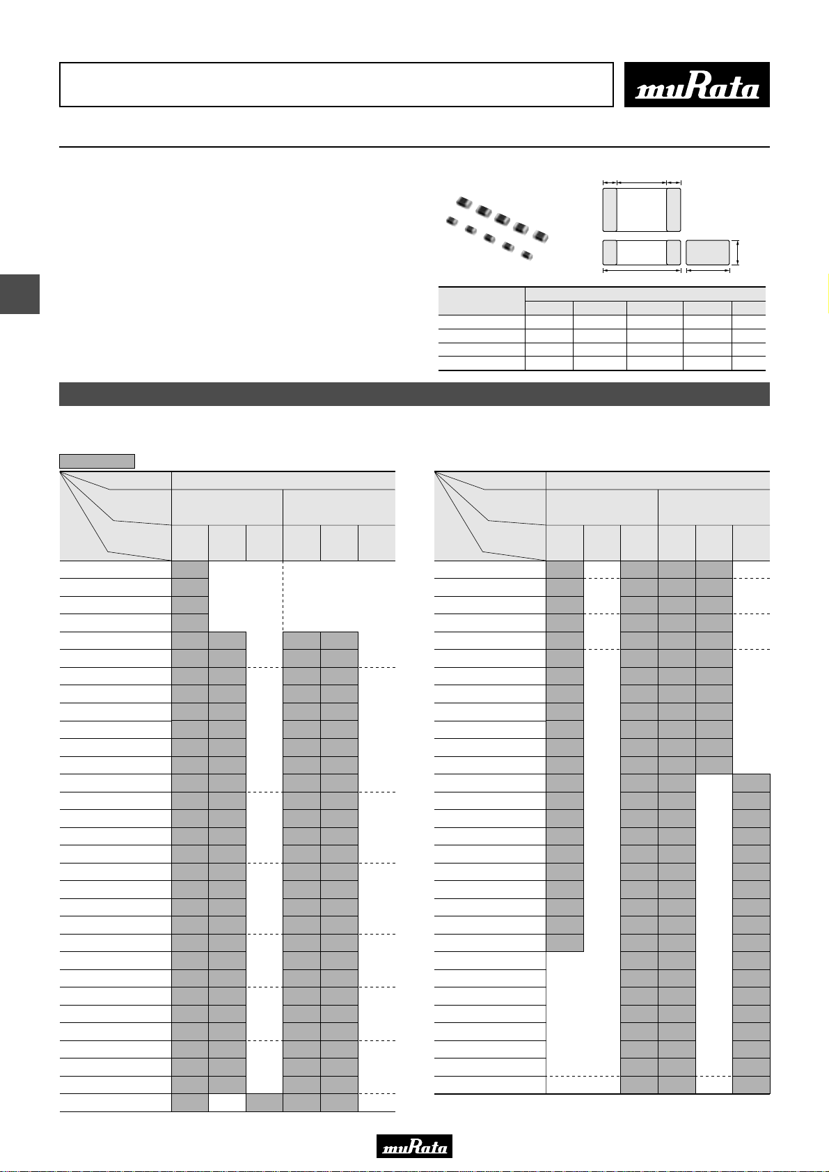
• This PDF catalog is downloaded from the website of Murata Manufacturing co., ltd. Therefore, it’s specifications are subject to change or our products in it may be discontinued without advance notice. Please check with our
!Note
• Please read rating and !CAUTION (for storage, operating, rating, soldering, mounting and handling) in this catalog to prevent smoking and/or burning, etc.
!Note
sales representatives or product engineers before ordering.
• This catalog has only typical specifications because there is no space for detailed specifications. Therefore, please approve our product specifications or transact the approval sheet for product specifications before ordering.
• This PDF catalog has only typical specifications because there is no space for detailed specifications. Therefore, please approve our product specifications or transact the approval sheet for product specifications before ordering.
Chip Monolithic Ceramic Capacitors
High Frequency GQM Series
e eg
■ Features
1. HiQ and low ESR at VHF, UHF, Microwave
2. Feature improvement, low power consumption for
mobile telecommunication. (Base station, terminal,
etc.)
5
■ Applications
High frequency circuit (Mobile telecommunication, etc.)
Part Number
GQM187
GQM188
GQM219
GQM219 (250V)
(50,100V)
LW T
1.6 ±0.15 0.8 ±0.15 0.2 to 0.5 0.50.7 ±0.1
1.6 ±0.1 0.8 ±0.1 0.2 to 0.5 0.50.8 ±0.1
2.0 ±0.1 1.25 ±0.1 0.2 to 0.7 0.70.85 ±0.1
2.0 ±0.15 1.25 ±0.15 0.2 to 0.7 0.70.85 ±0.15
Capacitance Table
L
Dimensions (mm)
C02E.pdf
09.9.18
T
W
e g min.
Temperature Compensating Type C0G(5C) Characteristics
7
Capacitance
The part number code is shown in ( ) and Unit is shown in [ ]. < >: EIA [inch] Code
98
ex.7: T Dimension [mm]
TC
LxW
[mm]
Rated Voltage
[Vdc]
0.10pF(R10)
0.20pF(R20)
0.30pF(R30)
0.40pF(R40)
0.50pF(R50)
0.75pF(R75)
1.0pF(1R0)
1.1pF(1R1)
1.2pF(1R2)
1.3pF(1R3)
1.5pF(1R5)
1.6pF(1R6)
1.8pF(1R8)
2.0pF(2R0)
2.2pF(2R2)
2.4pF(2R4)
2.7pF(2R7)
3.0pF(3R0)
3.3pF(3R3)
3.6pF(3R6)
3.9pF(3R9)
4.0pF(4R0)
4.3pF(4R3)
4.7pF(4R7)
5.0pF(5R0)
5.1pF(5R1)
5.6pF(5R6)
6.0pF(6R0)
6.2pF(6R2)
6.8pF(6R8)
7.0pF(7R0)
250
(2E)
7
7
7
7
7
7
7
7
7
7
7
7
7
7
7
7
7
7
7
7
7
7
7
7
7
7
7
7
7
7
7
1.6x0.8
(18)
<0603>
100
(2A)50(1H)
8
8
8
8
8
8
8
8
8
8
8
8
8
8
8
8
8
8
8
8
8
8
8
8
8
8
C0G(5C)
250
(2E)
8
9
9
9
9
9
9
9
9
9
9
9
9
9
9
9
9
9
9
9
9
9
9
9
9
9
9
9
2.0x1.25
(21)
<0805>
100
(2A)50(1H)
9
9
9
9
9
9
9
9
9
9
9
9
9
9
9
9
9
9
9
9
9
9
9
9
9
9
9
Rated Voltage
Capacitance
7.5pF(7R5)
8.0pF(8R0)
8.2pF(8R2)
9.0pF(9R0)
9.1pF(9R1)
100pF(101)
TC
LxW
[mm]
[Vdc]
10pF(100)
11pF(110)
12pF(120)
13pF(130)
15pF(150)
16pF(160)
18pF(180)
20pF(200)
22pF(220)
24pF(240)
27pF(270)
30pF(300)
33pF(330)
36pF(360)
39pF(390)
43pF(430)
47pF(470)
51pF(510)
56pF(560)
62pF(620)
68pF(680)
75pF(750)
82pF(820)
91pF(910)
250
(2E)
7
7
7
7
7
7
7
7
7
7
7
7
7
7
7
7
7
7
7
7
7
7
1.6x0.8
(18)
<0603>
100
(2A)50(1H)
C0G(5C)
250
(2E)
8
8
8
8
8
8
8
8
8
8
8
8
8
8
8
8
8
8
8
8
8
8
8
8
8
8
8
8
8
8
2.0x1.25
9
9
9
9
9
9
9
9
9
9
9
9
9
9
9
9
9
9
9
9
9
9
9
9
9
9
9
9
9
9
(21)
<0805>
100
(2A)50(1H)
9
9
9
9
9
9
9
9
9
9
9
9
9
9
9
9
9
9
9
9
9
9
9
9
9
9
9
9
9
9
 Loading...