

Page 1
Features
• Low-voltage and Standard-voltage Operation
– 5.0 (VCC = 4.5V to 5.5V)
– 2.7 (VCC = 2.7V to 5.5V)
• Internally Organized 4096 x 8, 8192 x 8
• 2-wire Serial Interface
• Schmitt Trigger, Filtered Inputs for Noise Suppression
• Bi-directional Data Transfer Protocol
• 100 kHz (2.7V) and 400 kHz (5V) Compatibility
• 32-byte Page Write Mode (Partial Page Writes Allowed)
• Self-timed Write Cycle (10 ms max)
• High Reliability
– Endurance: 1 Million Write Cycles
– Data Retention: 100 Years
– ESD Protection: >3,000V
2-wire
Serial EEPROM
Smart Card
Description
The AT24C32SC/64SC provides 32,768/65,536 bits of serial electrically erasable and
programmable read only memory (EEPROM) organized as 4096/8192 words of 8 bits
each. The devices are optimized for use in smart card applications where low-power
and low-voltage operation may be essential. The devices are available in several
standard ISO 7816 smart card modules (see Ordering Information). The entire family
is available in both high-voltage (4.5V to 5.5V) and low-voltage (2.7V to 5.5V)
versions. All devices are functionally equivalent to Atmel Serial EEPROM products
offered in standard IC packages (PDIP, SOIC, EIAJ, LAP), with the exception of the
slave address and Write Protect functions which are not required for smart card
applications.
Pin Configurations
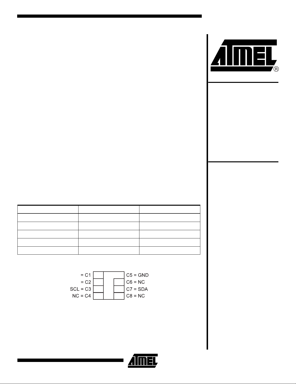
Pad Name Description ISO Module Contact
VCC Power Supply Voltage C1
GND Ground C5
SCL Serial Clock Input C3
SDA Serial Data Input/Output C7
NC No Connect C2, C4, C6, C8
Card Module Contact
Modules
32K (4096 x 8)
64K (8192 x 8)
AT24C32SC
AT24C64SC
VCC
NC
Rev. 1660A–10/00
1
Page 2
Absolute Maximum Ratings*
Operating Temperature.................................. -55°C to +125°C
Storage Temperature..................................... -65°C to +150°C
Voltage on Any Pin
with Respect to Ground.....................................-1.0V to +7.0V
Maximum Operating Voltage .......................................... 6.25V
DC Output Current........................................................ 5.0 mA
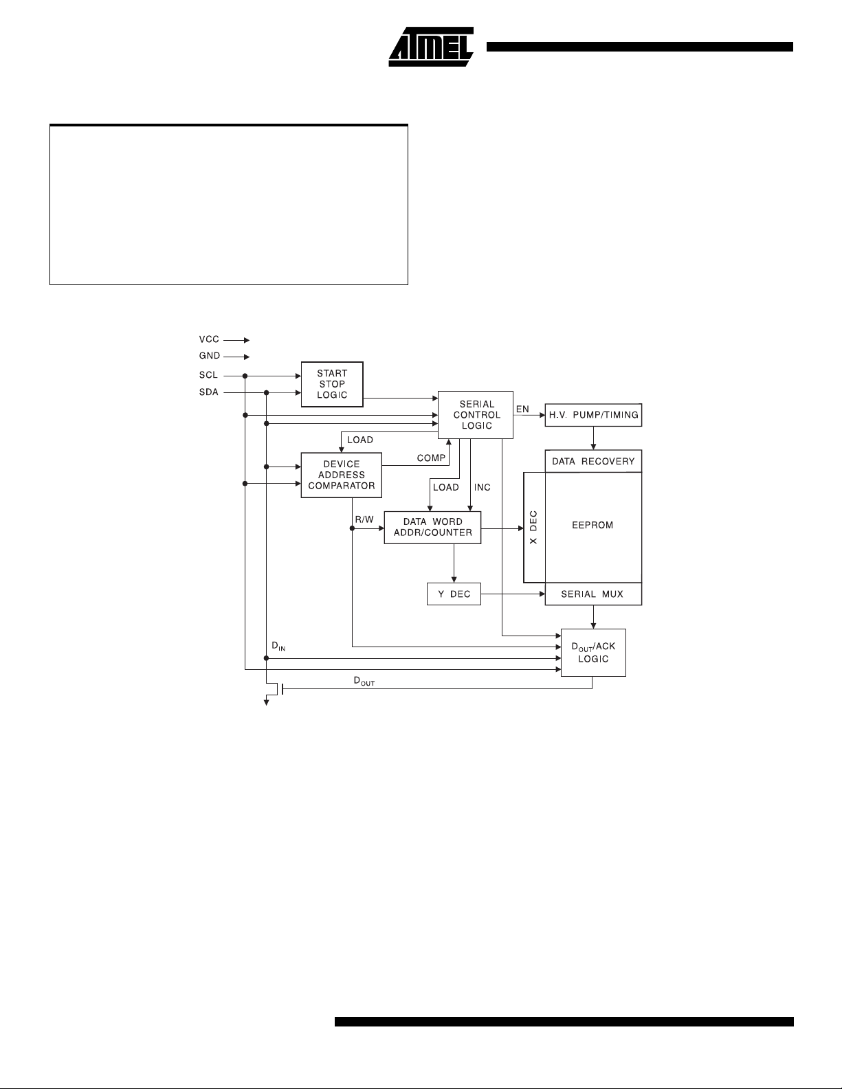
Block Diagram
*NOTICE: Stresses beyond those listed under “Absolute
Maximum Ratings” may cause permanent damage to the device. This is a stress rating only and
functional operation of the device at these or any
other conditions beyond those indicated in the
operational sections of this specification is not
implied. Exposure to absolute maximum rating
conditions for extended periods may affect
device reliability.
Pin Description
SERIAL CLOCK (SCL): The SCL input is used to positive
edge clock data into each EEPROM device and negative
edge clock data out of each device.
SERIAL DATA (SDA): The SDA pin is bidirectional for
serial data transfer. This pin is open-drain driven and may
be wire-ORed with any number of other open-drain or
open-collector devices.
2
AT25C32SC/64SC
Memory Organization
AT24C32SC/64SC, 32K/64K SERIAL EEPROM: The
32K/64K is internally organized as 128/256 pages of 32
bytes each. Random word addressing requires a 12/13 bit
data word address.
Page 3

AT25C32SC/64SC
Pin Capacitance
(1)
Applicable over recommended operating range from TA = 25°C, f = 1.0 MHz, VCC = +2.7V.
Symbol Test Condition Max Units Conditions
C
I/O
C
IN
Input/Output Capacitance (SDA) 8 pF V
I/O
= 0V
Input Capacitance (SCL) 6 pF VIN = 0V
Note: 1. This parameter is characterized and is not 100% tested.
DC Characteristics
Applicable over recommended operating range from: TAC = 0°C to +70°C, VCC = +2.7V to +5.5V (unless otherwise noted).
Symbol Parameter Test Condition Min Typ Max Units
V
V
I
I
I
I
CC1
CC2
CC1
CC2
SB1
SB2
Supply Voltage 2.7 5.5 V
Supply Voltage 4.5 5.5 V
Supply Current VCC = 5.0V Read at 100 kHz 0.4 1.0 mA
Supply Current VCC = 5.0V Write at 100 kHz 2.0 3.0 mA
Standby Current
(2.7V option)
Standby Current
(5V option)
V
= 2.7V
CC
V
= 5.5V 2.0
CC
= 4.5 - 5.5V VIN = VCC or GND 2.0 µA
V
CC
= VCC or GND
V
IN
0.5 µA
I
LI
I
LO
V
IL
V
IH
V
OL
Note: 1. V
Input Leakage Current VIN = V
Output Leakage
Current
Input Low Level
Input High Level
Output Low Level
min and VIH max are reference only and are not tested.
IL
(1)
(1)
(1)
= V
V
OUT
VCC = 3.0V IOL = 2.1mA 0.4 V
GND 0.10 3.0 µA
CC or
GND 0.05 3.0 µA
CC or
-0.6 VCC x 0.3 V
VCC x 0.7 VCC + 0.5 V
3
Page 4
AC Characteristics
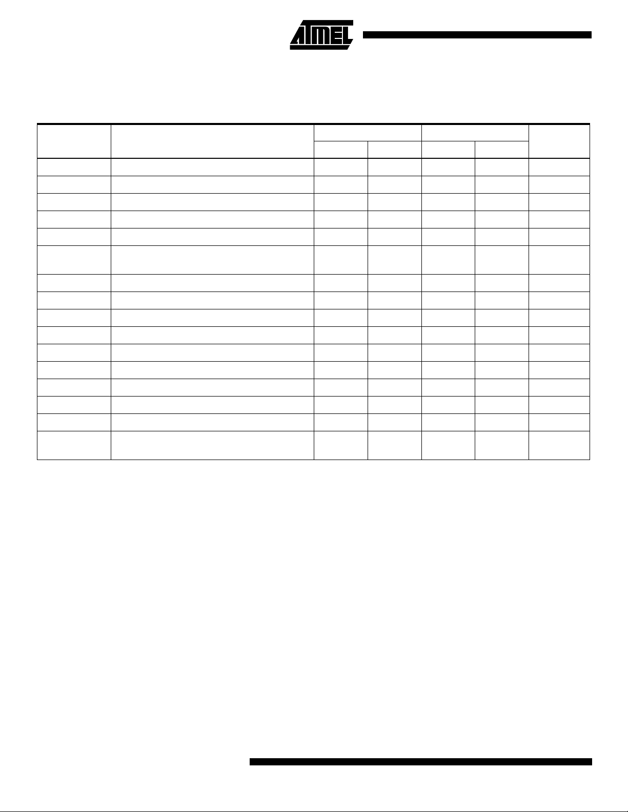
Applicable over recommended operating range from TA = 0°C to +70°C, VCC = +2.7V to +5.5V, CL = 1 TTL Gate and 100
pF (unless otherwise noted).
2.7-volt 5.0-volt
Symbol Parameter
f
SCL
t
LOW
t
HIGH
t
I
t
AA
t
BUF
t
HD.STA
t
SU.STA
t
HD.DAT
t
SU.DAT
t
R
t
F
t
SU.STO
t
DH
t
WR
Endurance
Clock Frequency, SCL 100 400 kHz
Clock Pulse Width Low 4.7 1.2 µs
Clock Pulse Width High 4.0 0.6 µs
Noise Suppression Time
(1)
Clock Low to Data Out Valid 0.1 4.5 0.1 0.9 µs
Time the bus must be free
before a new transmission can start
(1)
Start Hold Time 4.0 0.6 µs
Start Set-up Time 4.7 0.6 µs
Data In Hold Time 0 0 µs
Data In Set-up Time 200 100 ns
Inputs Rise Time
Inputs Fall Time
(1)
(1)
Stop Set-up Time 4.7 0.6 µs
Data Out Hold Time 100 50 ns
Write Cycle Time 10 10 ms
(1)
5.0V, 25°C, Page Mode 1M 1M
Note: 1. This parameter is characterized and is not 100% tested.
UnitsMin Max Min Max
100 50 ns
4.7 1.2 µs
1.0 0.3 µs
300 300 ns
Write
Cycles
Device Operation
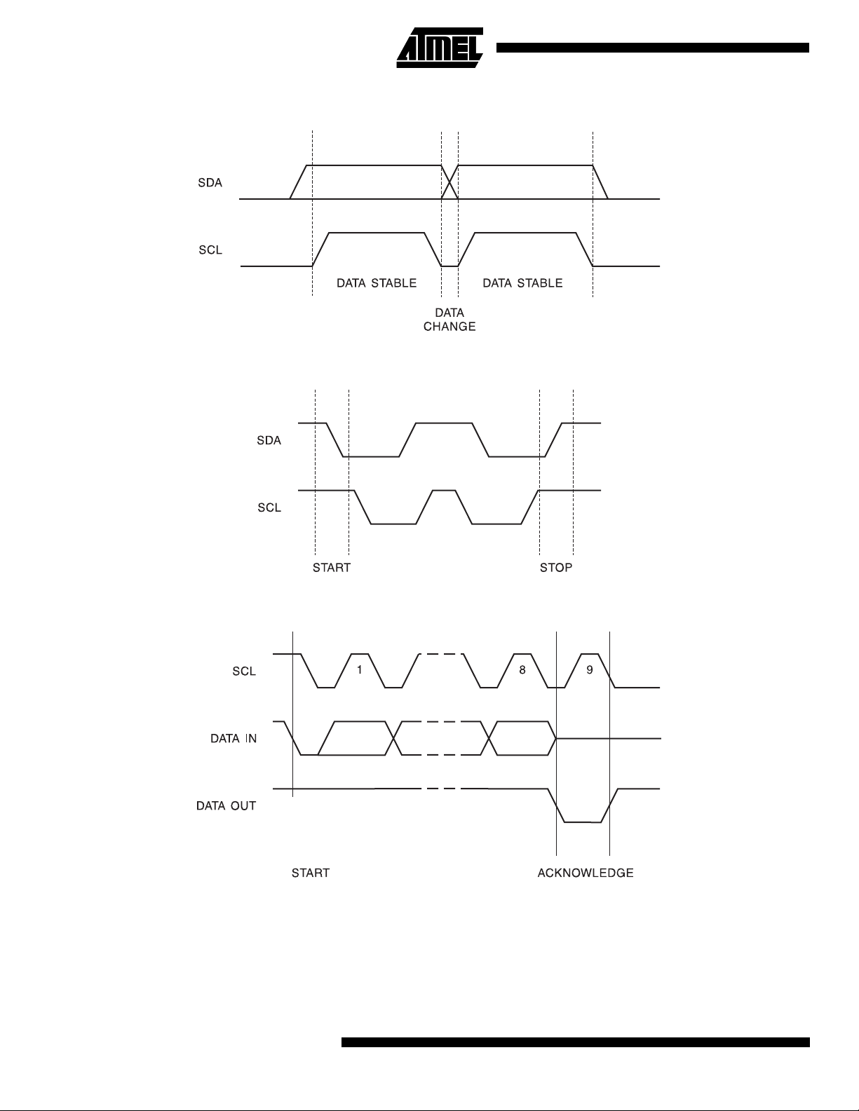
CLOCK and DATA TRANSITIONS: The SDA pin is nor-
mally pulled high with an external device. Data on the SDA
pin may change only during SCL low time periods (refer to
Data Validity timing diagram). Data changes during SCL
high periods will indicate a start or stop condition as
defined below.
START CONDITION: A high-to-low transition of SDA with
SCL high is a start condition which must precede any other
command (refer to Start and Stop Definition timing diagram).
STOP CONDITION: A low-to-high transition of SDA with
SCL high is a stop condition. After a read sequence, the
stop command will place the EEPROM in a standby power
mode (refer to Start and Stop Definition timing diagram).
4
AT25C32SC/64SC
ACKNOWLEDGE: All addresses and data words are seri-
ally transmitted to and from the EEPROM in 8-bit words.
The EEPROM sends a zero during the ninth clock cycle to
acknowledge that it has received each word.
STANDBY MODE: The AT24C32SC/64SC features a low
power standby mode which is enabled: a) upon power-up
and b) after the receipt of the STOP bit and the completion
of any internal operations.
MEMORY RESET: After an interruption in protocol, power
loss or system reset, any 2-wire part can be reset by following these steps:
1. Clock up to 9 cycles.
2. Look for SDA high in each cycle while SCL is high.
3. Create a start condition as SDA is high.
Page 5

Bus Timing SCL: Serial Clock, SDA: Serial Data I/O
Write Cycle Timing SCL: Serial Clock, SDA: Serial Data I/O
AT25C32SC/64SC
(1)
t
WR
Note: 1. The write cycle time tWR is the time from a valid stop condition of a write sequence to the end of the internal clear/write
cycle.
5
Page 6
Data Validity
Start and Stop Definition
Output Acknowledge
6
AT25C32SC/64SC
Page 7

AT25C32SC/64SC
Device Addressing
The 32K/64K EEPROM requires an 8-bit device address
word following a start condition to enable the chip for a read
or write operation (refer to Figure 1). The device address
word consists of a mandatory one, zero sequence for the
first four most significant bits as shown. This is common to
all 2-wire EEPROM devices.
The next three bits of the device address word are unused.
These three unused bits should be set to “0”.
The eighth bit of the device address is the read/write operation select bit. A read operation is initiated if this bit is high
and a write operation is initiated if this bit is low.
Upon a compare of the device address, the EEPROM will
output a zero. If a compare is not made, the device will
return to standby state.
Write Operations
BYTE WRITE: A write operation requires two 8-bit data
word addresses following the device address word and
acknowledgment. Upon receipt of this address, the
EEPROM will again respond with a zero and then clock in
the first 8-bit data word. Following receipt of the 8-bit data
word, the EEPROM will output a zero and the addressing
device, such as a microcontroller, must terminate the write
sequence with a stop condition. At this time the EEPROM
enters an internally-timed write cycle, t
memory. All inputs are disabled during this write cycle and
the EEPROM will not respond until the write is complete
(refer to Figure 2).
PAG E W R IT E: The 32K/64K EEPROM is capable of 32byte page writes.
A page write is initiated the same way as a byte write, but
the microcontroller does not send a stop condition after the
first data word is clocked in. Instead, after the EEPROM
acknowledges receipt of the first data word, the microcontroller can transmit up to 31 more data words. The
EEPROM will respond with a zero after each data word
received. The microcontroller must terminate the page
write sequence with a stop condition (refer to Figure 3).
The data word address lower five bits are internally incremented following the receipt of each data word. The higher
data word address bits are not incremented, retaining the
memory page row location. When the word address, internally generated, reaches the page boundary, the following
byte is placed at the beginning of the same page. If more
than 32 data words are transmitted to the EEPROM, the
data word address will “roll over” and previous data will be
overwritten.
, to the nonvolatile
WR
ACKNOWLEDGE POLLING: Once the internally-timed
write cycle has started and the EEPROM inputs are disabled, acknowledge polling can be initiated. This involves
sending a start condition followed by the device address
word. The read/write bit is representative of the operation
desired. Only if the internal write cycle has completed will
the EEPROM respond with a zero, allowing the read or
write sequence to continue.
Read Operations
Read operations are initiated the same way as write operations with the exception that the read/write select bit in the
device address word is set to one. There are three read
operations: current address read, random address read
and sequential read.
CURRENT ADDRESS READ: The internal data word
address counter maintains the last address accessed during the last read or write operation, incremented by one.
This address stays valid between operations as long as the
chip power is maintained. The address “roll over” during
read is from the last byte of the last memory page, to the
first byte of the first page. The address “roll over” during
write is from the last byte of the current page to the first
byte of the same page.
Once the device address with the read/write select bit set
to one is clocked in and acknowledged by the EEPROM,
the current address data word is serially clocked out. The
microcontroller does not respond with an input zero but
does generate a following stop condition (refer to Figure 4).
RANDOM READ: A random read requires a “dummy” byte
write sequence to load in the data word address. Once the
device address word and data word address are clocked in
and acknowledged by the EEPROM, the microcontroller
must generate another start condition. The microcontroller
now initiates a current address read by sending a device
address with the read/write select bit high. The EEPROM
acknowledges the device address and serially clocks out
the data word. The microcontroller does not respond with a
zero but does generate a following stop condition (refer to
Figure 5).
SEQUENTIAL READ: Sequential reads are initiated by
either a current address read or a random address read.
After the microcontroller receives a data word, it responds
with an acknowledge. As long as the EEPROM receives an
acknowledge, it will continue to increment the data word
address and serially clock out sequential data words. When
the memory address limit is reached, the data word
address will “roll over” and the sequential read will continue. The sequential read operation is terminated when
the microcontroller does not respond with a zero but does
generate a following stop condition (refer to Figure 6).
7
Page 8
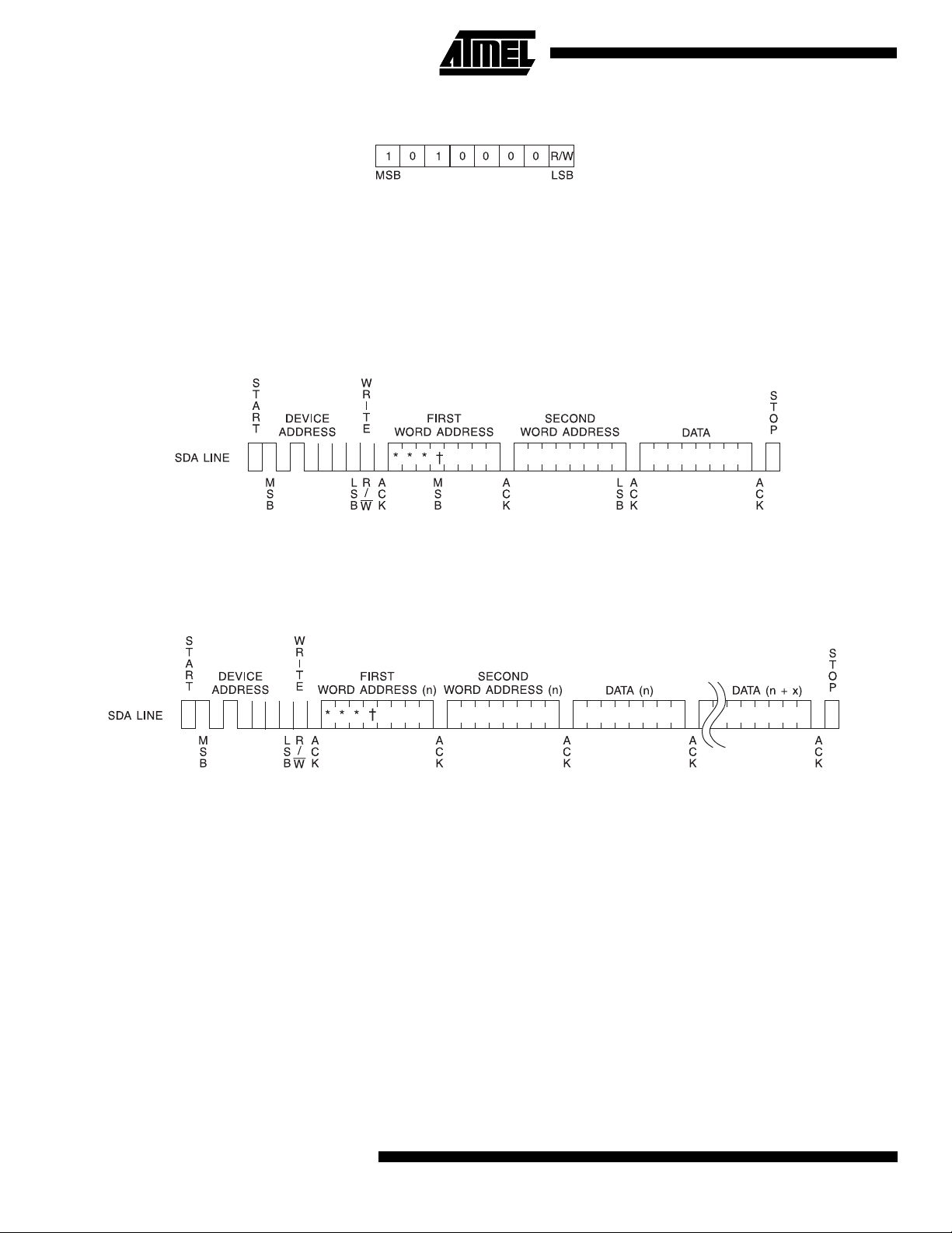
Figure 1. Device Address
Figure 2. Byte Write
Figure 3. Page Write
Notes: 1. * = DON’T CARE bits
2. † = DON’T CARE bits for the 32K
8
AT25C32SC/64SC
Page 9

Figure 4. Current Address Read
Figure 5. Random Read
AT25C32SC/64SC
Note: 1. * = DON’T CARE bits
Figure 6. Sequential Read
9
Page 10
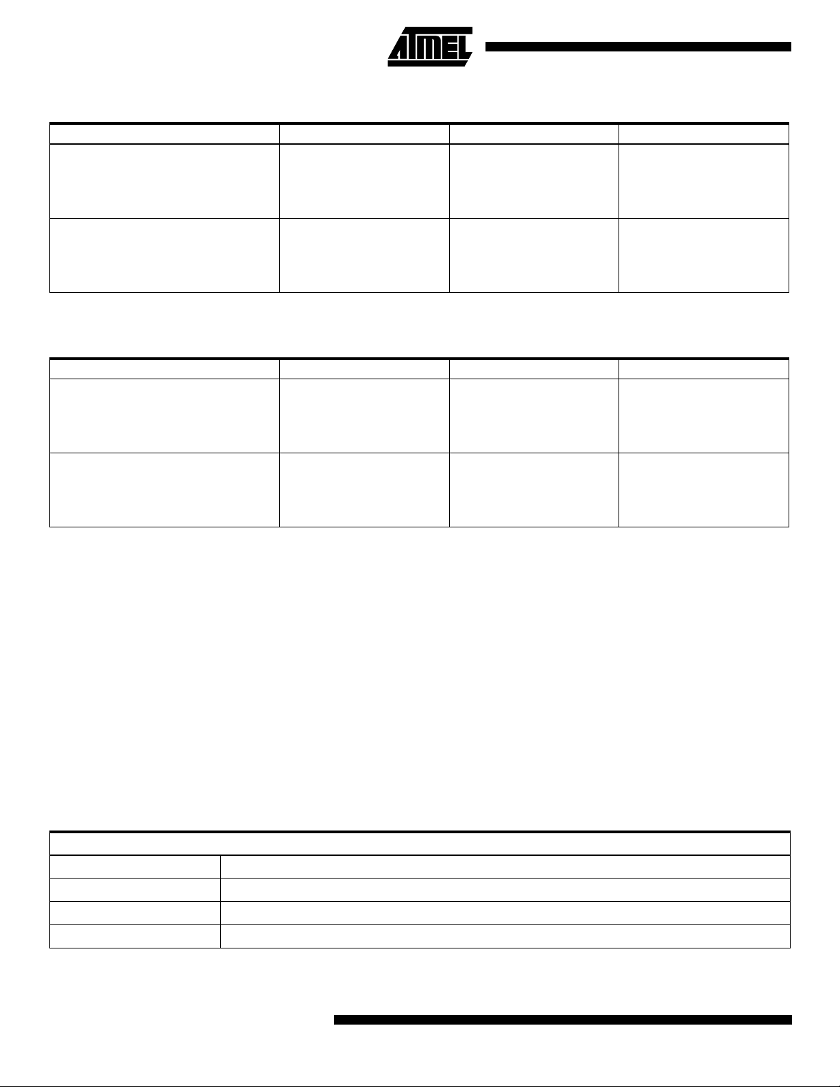
AT24C32SC Ordering Information
Ordering Code Package
AT24C32SC - 09AT - 2.7
AT24C32SC - 09BT - 2.7
AT24C32SC - 09CT - 2.7
AT24C32SC - 09DT - 2.7
AT24C32SC - 09AT
AT24C32SC - 09BT
AT24C32SC - 09CT
AT24C32SC - 09DT
M2 - A Module
M2 - B Module
M4 - C Module
M4 - D Module
M2 - A Module
M2 - B Module
M4 - C Module
M4 - D Module
AT24C64SC Ordering Information
Ordering Code Package
AT24C64SC - 09AT - 2.7
AT24C64SC - 09BT - 2.7
AT24C64SC - 09CT - 2.7
AT24C64SC - 09DT - 2.7
AT24C64SC - 09AT
AT24C64SC - 09BT
AT24C64SC - 09CT
AT24C64SC - 09DT
M2 - A Module
M2 - B Module
M4 - C Module
M4 - D Module
M2 - A Module
M2 - B Module
M4 - C Module
M4 - D Module
(1)
(1)
Voltage Range Temperature Range
2.7V to 5.5V Commercial
(0°C to 70°C)
4.5V to 5.5V Commercial
(0°C to 70°C)
Voltage Range Temperature Range
2.7V to 5.5V Commercial
(0°C to 70°C)
4.5V to 5.5V Commercial
(0°C to 70°C)
Package Type
M2 - A Module M2 ISO 7816 Smart Card Module
M2 - B Module M2 ISO 7816 Smart Card Module with Atmel Logo
M4 - C Module M4 ISO 7816 Smart Card Module
M4 - D Module M4 ISO 7816 Smart Card Module with Atmel Logo
Note: 1. Formal drawings may be obtained from an Atmel Sales Office.
10
AT25C32SC/64SC
(1)
Page 11
AT25C32SC/64SC
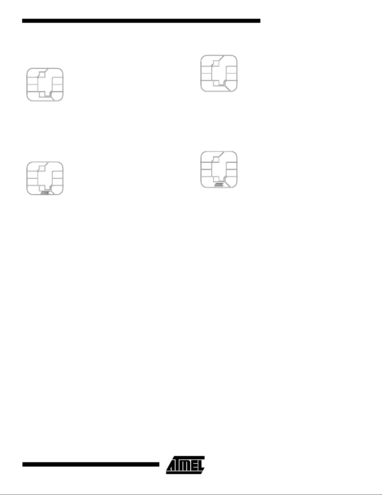
Smart Card Modules
M2 - A Module - Ordering Code: 09AT
Module Size: M2
Dimension
Glob Top: Square: 8.6 x 8.6 mm
Thickness: 0.58 mm max.
Pitch: 14.25 mm
M2 - B Module - Ordering Code: 09BT
Module Size: M2
Dimension
Glob Top: Square: 8.6 x 8.6 mm
Thickness: 0.58 mm max.
Pitch: 14.25 mm
(1)
: 12.6 x 11.4 mm
(1)
: 12.6 x 11.4 mm
M4 - C Module - Ordering Code: 09CT
Module Size: M4
Dimension
Glob Top: Square: 8.6 x 8.6 mm
Thickness: 0.58 mm
Pitch: 14.25 mm
M4 - D Module - Ordering Code: 09DT
Module Size: M4
Dimension
Glob Top: Square: 8.6 x 8.6 mm
Thickness: 0.58 mm max.
Pitch: 14.25 mm
Note: 1. The module dimensions listed refer to the dimen-
(1)
: 12.6 x 12.6 mm
(1)
: 12.6 x 12.6 mm
sions of the exposed metal contact area. The actual
dimensions of the module after excise or punching
from the carrier tape are generally 0.4 mm greater in
both directions (i.e. a punched M2 module will yield
13.0 x 11.8 mm).
11
Page 12

Atmel Headquarters Atmel Operations
Corporate Headquarters
2325 Orchard Parkway
San Jose, CA 95131
TEL (408) 441-0311
FAX (408) 487-2600
Europe
Atmel SarL
Route des Arsenaux 41
Casa Postale 80
CH-1705 Fribourg
Switzerland
TEL (41) 26-426-5555
FAX (41) 26-426-5500
Asia
Atmel Asia, Ltd.
Room 1219
Chinachem Golden Plaza
77 Mody Road Tsimhatsui
East Kowloon
Hong Kong
TEL (852) 2721-9778
FAX (852) 2722-1369
Japan
Atmel Japan K.K.
9F, Tonetsu Shinkawa Bldg.
1-24-8 Shinkawa
Chuo-ku, Tokyo 104-0033
Japan
TEL (81) 3-3523-3551
FAX (81) 3-3523-7581
Atmel Colorado Springs
1150 E. Cheyenne Mtn. Blvd.
Colorado Springs, CO 80906
TEL (719) 576-3300
FAX (719) 540-1759
Atmel Rousset
Zone Industrielle
13106 Rousset Cedex
France
TEL (33) 4-4253-6000
FAX (33) 4-4253-6001
Atmel Smart Card ICs
Scottish Enterprise Technology Park
East Kilbride, Scotland G75 0QR
TEL (44) 1355-803-000
FAX (44) 1355-242-743
Atmel Grenoble
Avenue de Rochepleine
BP 123
38521 Saint-Egreve Cedex
France
TEL (33) 4-7658-3000
FAX (33) 4-7658-3480
Fax-on-Demand
North America:
1-(800) 292-8635
International:
1-(408) 441-0732
e-mail
Web Site
http://www.atmel.com
BBS
1-(408) 436-4309
© Atmel Corporation 2000.
Atmel Corporation makes no warranty for the use of its products, other than those expressly contained in the Company’s standard war-
ranty which is detailed in Atmel’s Terms and Conditions located on the Company’s web site. The Company assumes no responsibility for
any errors which may appear in this document, reserves the right to change devices or specifications detailed herein at any time without
notice, and does not make any commitment to update the information contained herein. No licenses to patents or other intellectual property of Atmel are granted by the Company in connection with the sale of Atmel products, expressly or by implication. Atmel’s products are
not authorized for use as critical components in life support devices or systems.
Marks bearing ® and/or ™ are registered trademarks and trademarks of Atmel Corporation.
Terms and product names in this document may be trademarks of others.
Printed on recycled paper.
1660A–10/00/xM
 Loading...