

Page 1

ELECTRICAL & POWER CONTROL
Revision: October 2006
2007 G35 Sedan
A
B
SECTION CHG
CONTENTS
BASIC INSPECTION ....................................3
DIAGNOSIS AND REPAIR WORKFLOW ..........3
Work Flow .................................................................3
FUNCTION DIAGNOSIS ...............................6
CHARGING SYSTEM .......................................... 6
System Diagram ........................................................6
System Description ...................................................6
Component Parts Location . .......................................6
Component Description ......................... ...................7
POWER GENERATION VOLTAGE VARI-
ABLE CONTROL SYSTEM .................................
System Diagram ........................................................8
System Description ...................................................8
Component Parts Location . .......................................8
Component Description .............................................8
CHARGING SYSTEM
CHARGING SYSTEM .......................................18
Symptom Table .......................................................18
PRECAUTION ..............................................19
PRECAUTIONS .................................................19
Precaution for Supplemental Restraint Syste m
(SRS) "AIR BAG" and "SEAT BELT PRE-TEN-
SIONER" .................................................................
Precaution for Power Generation Voltage Vari able
Control System ................ ... ... ..................................
PREPARATION ...........................................20
PREPARATION .................................................20
8
Special Service Tool ................................................20
Commercial Service Tool ........................................20
ON-VEHICLE MAINTENANCE ....................21
19
19
C
D
E
F
G
H
I
J
K
COMPONENT DIAGNOSIS .........................10
B TERMINAL CIRCUIT ......................................10
Description ..............................................................10
Diagnosis Procedure ........................... ... ... ... .... .......10
L TERMINAL CIRCUIT (OPEN) .........................11
Description ..............................................................11
Diagnosis Procedure ........................... ... ... ... .... .......11
L TERMINAL CIRCUIT (SHORT) .......................13
Description ..............................................................13
Diagnosis Procedure ........................... ... ... ... .... .......13
S TERMINAL CIRCUIT ......................................14
Description ..............................................................14
Diagnosis Procedure ........................... ... ... ... .... .......14
CHARGING SYSTEM .........................................15
Wiring Diagram — CHARGING SYSTEM — ..........15
SYMPTOM DIAGNOSIS ..............................18
CHARGING SYSTEM PRELIMINARY IN-
SPECTION ........................................................
Inspection Procedure ...............................................21
POWER GENERATION VOLTAGE VARIABLE CONTROL SYSTEM OPERATION IN-
SPECTION ........................................................
Inspection Procedure ...............................................22
ON-VEHICLE REPAIR .................................24
ALTERNATOR ..................................................24
2WD ................................. ................ ................ ...........24
2WD : Exploded View ..............................................24
2WD : Removal and Installation ..............................25
2WD : Inspection .....................................................26
AWD ................................... ........................................26
AWD : Exploded View .............................................26
AWD : Removal and Installation ..............................27
AWD : Inspection .....................................................28
CHG-1
21
22
L
CHG
N
O
P
Page 2

SERVICE DATA AND SPECIFICATIONS
Revision: October 2006
2007 G35 Sedan
(SDS) ........................................................... 29
SERVICE DATA AND SPECIFICATIONS
(SDS) .................................................................
Alternator ................................................................29
29
CHG-2
Page 3

< BASIC INSPECTION >
B
Revision: October 2006
2007 G35 Sedan
DIAGNOSIS AND REPAIR WORKFLOW
BASIC INSPECTION
DIAGNOSIS AND REPAIR WORKFLOW
Work Flow INFOID:0000000000964263
OVEROALL SEQUENCE
A
B
C
D
E
F
G
H
I
J
K
L
CHG
N
O
P
DETAILED FLOW
JSMIA0009G
CHG-3
Page 4

DIAGNOSIS AND REPAIR WORKFLOW
Revision: October 2006
2007 G35 Sedan
< BASIC INSPECTION >
NOTE:
To ensure a complete and thorough diagnosis, the battery, starter and alternator test segments must be done
as a set from start to finish.
1.PRELIMINARY INSPECTION
Perform the preliminary inspection. Refer to CHG-21, "
>> GO TO 2.
Inspection Procedure".
2.STOP POWER GENERATION VOLTAGE VARIABLE CONTROL SYSTEM
Stop the operation of the power generation voltage variable control in either of the following procedures.
• After sel ecting “ENGINE” of “SELECT SYSTEM” using CONSULT-III, set the DUTY value of “AL TERNATOR
DUTY” to 0 % by selecting “ALTERNATOR DUTY” of “Active Test”. Continue “Active Test” until the end of
inspection. (When the DUTY value is 0 or 100 %, the normal power generation is performed according to the
characteristic of the IC regulator of the alternator.)
• Turn the ignition switch OFF, and disconnect the battery current sensor connector. [However, DTC (P1550 P1554) of the engine might remain. After finishing the inspection, connect the battery current sensor connector and erase the self-diagnostic results history of the engine using CONSULT-III.]
>> GO TO 3.
3.DIAGNOSIS WITH STARTING/CHARGING SYSTEM TESTER
Perform the charging system test using St arting/Charging System Tester (SST: J-44373). For det ails and operating instructions, refer to Technical Service Bulletin.
Test result
CHARGING SYSTEM NOMAL>>Charging system is normal and will also show “DIODE RIPPLE” test result.
NO CHARGING VOLTAGE>>GO TO 4.
LOW CHARGING VOLTA GE>>GO TO 12.
HIGH CHARGING VOLTAGE>>GO TO 14.
DIODE RIPPLE NORMAL>>Diode ripple is OK and will also show “CHARGING VOLTAGE” test result.
EXCESS RIPPLE DETECTED>>Replace the alternator. Perform “DIODE RIPPLE” test again using Starting/
Charging System Tester (SST: J-44373) to confirm repair.
DIODE RIPPLE NOT DETECTED>>GO TO 4.
4.INSPECTION WITH CHARGE WARNING LAMP (IGNIT ION SWITCH IS ON)
Turn the ignition switch ON.
Does the charge warning lamp illuminate?
YES >> GO TO 6.
NO >> GO TO 5.
5.“L” TERMINAL CIRCUIT (OPEN) INSPECTION
Check “L” terminal circuit (open). Refer to CHG-11, "
“L” terminal circuit normal?
Is the
YES >> Replace alternator.
NO >> Repair as needed.
Diagnosis Procedure".
6.INSPECTION WITH CHARGE WARNING LAMP (IDLING)
Start the engine and run it at idle.
Does the charge warning lamp turn OFF?
YES >> GO TO 9.
NO >> GO TO 7.
7.“L” TERMINAL CIRCUIT (SHORT) INSPECTION
Check “L” terminal circuit (short). Refer to CHG-13, "
“L” terminal circuit normal?
Is the
YES >> GO TO 8.
NO >> Repair as needed.
Diagnosis Procedure".
CHG-4
Page 5

< BASIC INSPECTION >
Revision: October 2006
2007 G35 Sedan
DIAGNOSIS AND REPAIR WORKFLOW
8.“S” TERMINAL CIRCUIT INSPECTION
Check “S” terminal circuit. Refer to CHG-14, "
“S” terminal circuit normal?
Is the
YES >> GO TO 10.
NO >> Repair as needed.
Diagnosis Procedure".
9.INSPECTION WITH CHARGE WARNING LAMP (ENGINE AT 3,000 RPM)
Increase and maintain the engine speed at 3,000 rpm.
Does the charge warning lamp remain off?
YES >> GO TO 11.
NO >> GO TO 10.
10.INSPECTION OF ALTERNATOR PULLEY
Check alternator pulley. Refer to CHG-26, "
Is alternator pulley normal?
YES >> Replace alternator.
NO >> Repair as needed.
2WD : Inspection" (2WD) or CHG-28, "AWD : Inspection" (AWD).
11.“B” TERMINAL CIRCUIT INSPECTION
Check “B” terminal circuit. Refer to CHG-10, "
“B” terminal circuit normal?
Is
YES >> Replace alternator.
NO >> Repair as needed.
Diagnosis Procedure".
12.“B” TERMINAL CIRCUIT INSPECTION
A
B
C
D
E
F
G
H
Check “B” terminal circuit. Refer to CHG-10, "
Is
“B” terminal circuit normal?
YES >> GO TO 13.
NO >> Repair as needed.
Diagnosis Procedure".
13.INSPECTION OF ALTERNATOR PULLEY
Check alternator pulley. Refer to CHG-26, "
Is alternator pulley normal?
YES >> Replace alternator.
NO >> Repair as needed.
2WD : Inspection" (2WD) or CHG-28, "AWD : Inspection" (AWD).
14.“S” TERMINAL CIRCUIT INSPECTION
Check “S” terminal circuit. Refer to CHG-14, "
Is the
“S” terminal circuit normal?
YES >> Replace alternator.
NO >> Repair as needed.
Diagnosis Procedure".
I
J
K
L
CHG
N
O
P
CHG-5
Page 6

CHARGING SYSTEM
B
Revision: October 2006
2007 G35 Sedan
< FUNCTION DIAGNOSIS >
FUNCTION DIAGNOSIS
CHARGING SYSTEM
System Diagram INFOID:0000000000964264
JSMIA0008G
System Description INFOID:0000000000964265
The alternator provides DC voltage to operate the vehicle's electrical system and to keep the battery charged.
The voltage output is controlled by the IC regulator.
Component Parts Location INFOID:0000000000964266
JSMIA0010ZZ
1. Battery 2. IPDM E/R 3. Alternator
4. Charge warning lamp
A. Engine room dash panel (RH) B. Engine C. Combination meter
CHG-6
Page 7

CHARGING SYSTEM
Revision: October 2006
2007 G35 Sedan
< FUNCTION DIAGNOSIS >
Component Description INFOID:0000000000964267
Component part Description
“B” terminal Refer to CHG-10, "
“S” terminal Refer to CHG-14, "
Alternator
Combination meter (Charge warning lamp)
IPDM E/R
“L” terminal Refer to CHG-11, "Description".
“C” terminal
Used for the power generation voltage variable control system.
Refer to CHG-8, "
The IC regulator warning function activates to illuminate the
charge warning lamp, if any of the following symptoms occur while
alternator is operating:
• Excessive voltage is produced.
• No voltage is produced.
Used for the power generation voltage variable control system.
Refer to CHG-8, "
Description".
Description".
System Description".
System Description".
A
B
C
D
E
F
G
H
I
J
K
L
CHG
N
O
P
CHG-7
Page 8

POWER GENERATION VOLTAGE VARIABLE CONTROL SYSTEM
Revision: October 2006
2007 G35 Sedan
< FUNCTION DIAGNOSIS >
POWER GENERATION VOLTAGE VARIABLE CONTROL SYSTEM
System Diagram INFOID:0000000000964268
SKIB5009E
System Description INFOID:0000000000964269
By performing the power generation voltage variable control, the engine load due to the power generation of
the alternator is reduced and fuel consumption is decreased.
NOTE:
When any malfunction is detected in the power generation voltage variable control system, the power generation is performed according to the characteristic of the IC regulator of the alternator.
Component Parts Location INFOID:0000000000964270
1. Battery 2. IPDM E/R 3. Battery current sensor
4. ECM 5. Alternator
A. Engine room dash panel (RH) B. Behind glove box C. Engine
Component Description INFOID:0000000000964271
JSMIA0011ZZ
CHG-8
Page 9

POWER GENERATION VOLTAGE VARIABLE CONTROL SYSTEM
Revision: October 2006
2007 G35 Sedan
< FUNCTION DIAGNOSIS >
Battery current sensor
ECM
IPDM E/R
Alternator (IC regulator)
Component part Description
Battery current sensor is installed to the battery cable at the negative terminal, and it detects the charging/discharging current of
the battery and sends the voltage signal to ECM according to the
current value.
Battery current sensor detects the charging/discharging current of
the battery. ECM judges the battery condition based on this signal.
ECM judges whether to perform the power generation voltage
variable control according to the battery condition.
When performing the power generation voltage variable control,
ECM calculates the target power generation voltage according to
the battery condition and sends the calculated value as the power
generation command value to IPDM E/R.
IPDM E/R converts the receiv ed power generation command value into the power generation command signal (PWM signal) and
sends it to the IC regulator.
IC regulator controls the power generation voltage by the target
power generation voltage based on the received power generation
command signal.
When there is no power generation command signal, the alternator performs the normal power generation according to the characteristic of the IC regulator.
A
B
C
D
E
F
G
H
I
J
K
L
CHG
N
O
P
CHG-9
Page 10

B TERMINAL CIRCUIT
Revision: October 2006
2007 G35 Sedan
< COMPONENT DIAGNOSIS >
COMPONENT DIAGNOSIS
B TERMINAL CIRCUIT
Description INFOID:0000000000964272
“B” terminal circuit supplies power to charge the battery and operate the vehicle’s electrical system.
Diagnosis Procedure INFOID:0000000000964273
1.CHECK “B” TERMINAL CONNECTION
1. Turn ignition switch OFF.
2. Check if “B” terminal is clean and tight.
Is the inspection result normal?
YES >> GO TO 2.
NO >> Repair “B” terminal connection. Confirm repair by performing complete Starting/Charging system
test. Refer to Technical Service Bulletin.
2.CHECK “B” TERMINAL CIRCUIT
Check voltage between alternator “B” terminal and ground.
Terminals
Alternator “B” terminal Terminal
E203 1 Ground Battery voltage
Is the inspection result normal?
YES >> GO TO 3.
NO >> Check harness for open between alternator and fusible link.
(–)
3.CHECK “B” TERMINAL CONNECTION (VOLTAGE DROP TEST)
Voltage (Approx.)(+)
1. Start engine, then engine running at idle and warm.
2. Check voltage between battery positive terminal and alternator “B” terminal.
Terminals
(+)
Battery positive terminal E203 1 Less than 0.2 V
Is the inspection result normal?
YES >> “B” terminal circuit is normal. Refer to CHG-3, "Work F low".
NO >> Check harness between battery and alternator for poor continuity.
Alternator “B” terminal Terminal
(–)
Voltage (Approx.)
CHG-10
Page 11
< COMPONENT DIAGNOSIS >
Revision: October 2006
2007 G35 Sedan
L TERMINAL CIRCUIT (OPEN)
L TERMINAL CIRCUIT (OPEN)
Description INFOID:0000000000964274
The “L” terminal circuit controls the charge warning lamp. The charge warning lamp illuminates when the ignition switch is set to ON or START. When the alternator is providing sufficient voltage with the engine running,
the charge warning lamp will go off. If the charge warning lamp illuminates with the engi ne running, a malfunction is indicated.
Diagnosis Procedure INFOID:0000000000964275
1.CHECK “L” TERMINAL CONNECTION
1. Turn ignition switch OFF.
2. Check if “L” terminal is clean and tight.
Is the inspection result normal?
YES >> GO TO 2.
NO >> Repair “L” terminal connection. Confirm repair by performing complete Starting/Charging system
test. Refer to Technical Service Bulletin.
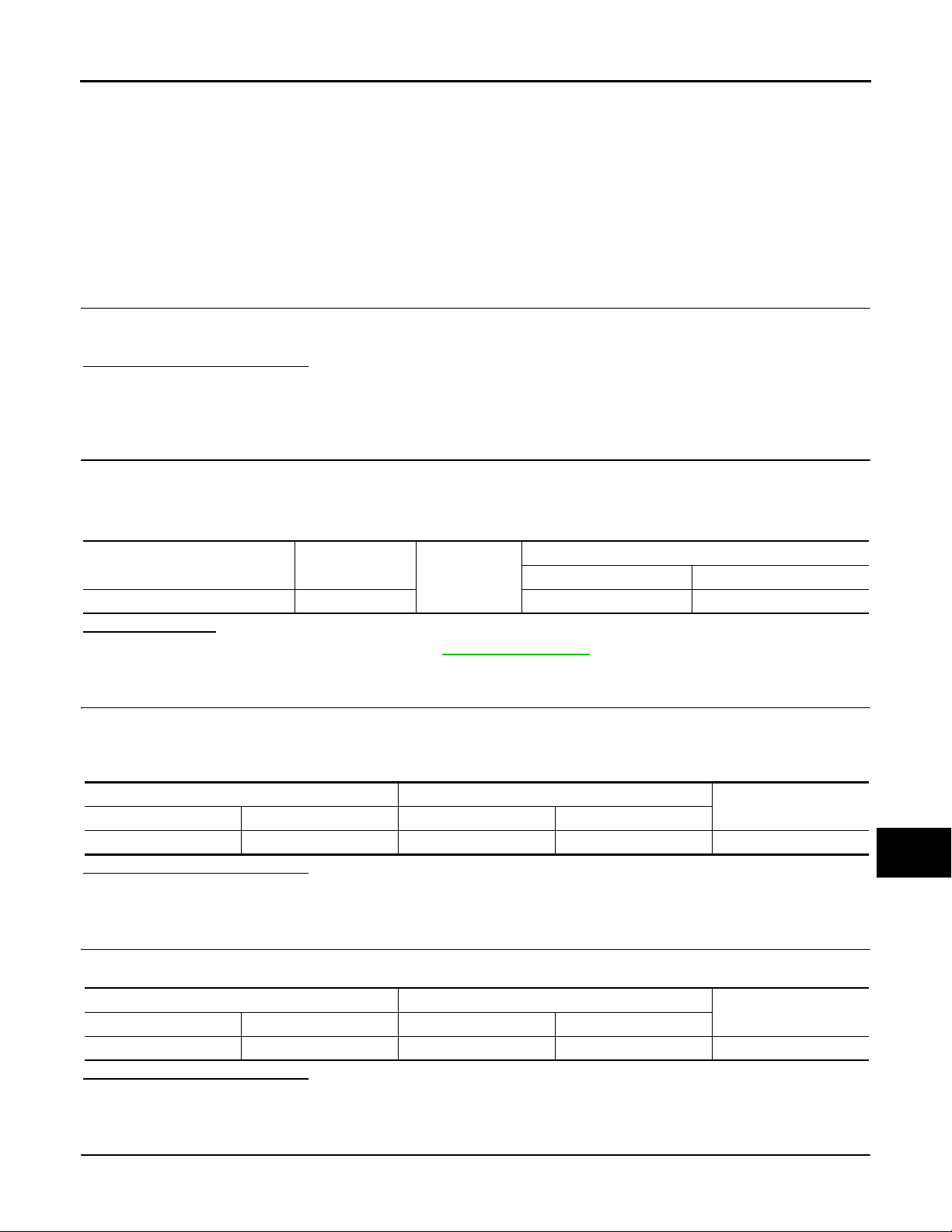
2.CHECK “L” TERMINAL CIRCUIT (OPEN)
1. Disconnect alternator connector.
2. Apply ground to alternator harness connector terminal.
3. Check condition the charge warning lamp with the ignition switch in the ON position.
Alternator harness connector Terminal
F36 2 ON illuminate
Does it illuminate?
YES >> “L” terminal circuit is normal. Refer to CHG-3, "Work Flow".
NO >> GO TO 3.
Ground
Ignition switch position Charge warning lamp
Condition
3.CHECK HARNESS CONTINUITY (OPEN CIRCUIT)
A
B
C
D
E
F
G
H
I
J
1. Disconnect the battery cable from the negative terminal.
2. Disconnect the combination meter connector.
3. Check continuity between alternator harness connector and combination meter harness connector.
Alternator harness connector Combination meter harness connector
Connector No. Terminal No. Connector No. Terminal No.
F36 2 M53 6 Existed
Is the inspection result normal?
YES >> GO TO 4.
NO >> Repair the harness or connector.
Continuity
4.CHECK HARNESS CONTINUITY (OPEN CIRCUIT)
Check continuity between combination meter harness connector and fuse block.
Combination meter harness connector Fuse block
Connector No. Terminal No. Connector No. Terminal No.
M53 21 M3 12C Existed
Is the inspection result normal?
YES >> GO TO 5.
NO >> Repair the harness.
Continuity
5.CHECK POWER SUPPLY CIRCUIT
1. Connect the battery cable to the negative terminal.
K
L
CHG
N
O
P
CHG-11
Page 12

L TERMINAL CIRCUIT (OPEN)
Revision: October 2006
2007 G35 Sedan
< COMPONENT DIAGNOSIS >
2. Check voltage between combination meter harness connector and ground.
Terminals
(+)
Combination meter
harness connector
M53 21 Ground
Terminal
(–)
When the ignition switch is in
Is the inspection result normal?
YES >> Replace combination meter.
NO >> Inspect the power supply circuit. Refer to PG-50, "
Condition Voltage (Approx.)
ON position
Wiring Diagram — Ignition Power Supply —".
Battery voltage
CHG-12
Page 13
< COMPONENT DIAGNOSIS >
Revision: October 2006
2007 G35 Sedan
L TERMINAL CIRCUIT (SHORT)
L TERMINAL CIRCUIT (SHORT)
Description INFOID:0000000000964276
The “L” terminal circuit controls the charge warning lamp. The charge warning lamp illuminates when the ignition switch is set to ON or START. When the alternator is providing sufficient voltage with the engine running,
the charge warning lamp will go off. If the charge warning lamp illuminates with the engi ne running, a malfunction is indicated.
Diagnosis Procedure INFOID:0000000000964277
1.CHECK “L” TERMINAL CIRCUIT (SHORT)
1. Turn ignition switch OFF.
2. Disconnect alternator connector.
3. Turn ignition switch ON.
Charge warning lamp should illuminate?
YES >> GO TO 2.
NO >> Refer to CHG-3, "
Work Fl ow".
2.CHECK HARNESS CONTINUITY (SHORT CIRCUIT)
1. Turn the ignition switch OFF.
2. Disconnect the battery cable from the negative terminal.
3. Disconnect combination meter connector.
4. Check continuity between combination meter harness connector and ground.
Combination meter harness connector
Connector No. Terminal No.
M53 6 Not existed
Is the inspection result normal?
YES >> Replace combination meter.
NO >> Repair the harness.
Ground
Continuity
A
B
C
D
E
F
G
H
I
J
K
L
CHG
N
O
P
CHG-13
Page 14

S TERMINAL CIRCUIT
Revision: October 2006
2007 G35 Sedan
< COMPONENT DIAGNOSIS >
S TERMINAL CIRCUIT
Description INFOID:0000000000964278
The output voltage of the alternator is controlled by the IC regulator at the “S” terminal detecting the input voltage.
The “S” terminal circuit detects the battery voltage to adjust the alternator output voltage with the IC regulator.
Diagnosis Procedure INFOID:0000000000964279
1.CHECK “S” TERMINAL CONNECTION
1. Turn ignition switch OFF.
2. Check if “S” terminal is clean and tight.
Is the inspection result normal?
YES >> GO TO 2.
NO >> Repair “S” terminal connection. Confirm repair by performing complete Starting/Charging system
test. Refer to Technical Service Bulletin.
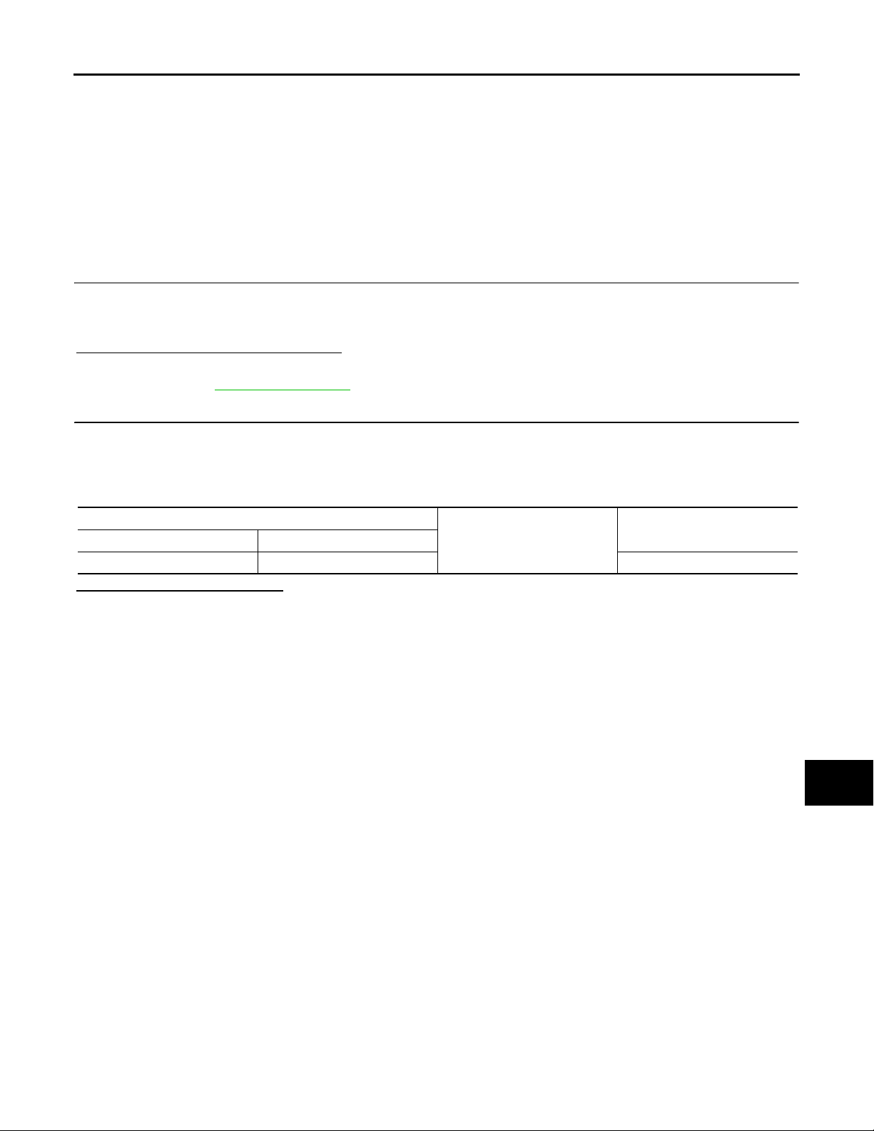
2.CHECK “S” TERMINAL CIRCUIT
Check voltage between alternator harness connector and ground.
Terminals
Voltage (Approx.)(+)
Alternator harness connector Terminal
F36 3 Ground Battery voltage
Is the inspection result normal?
YES >> Refer to CHG-3, "Work Flow".
NO >> Check harness for open between alternator and fuse.
(–)
CHG-14
Page 15

< COMPONENT DIAGNOSIS >
B
Revision: October 2006
2007 G35 Sedan
CHARGING SYSTEM
CHARGING SYSTEM
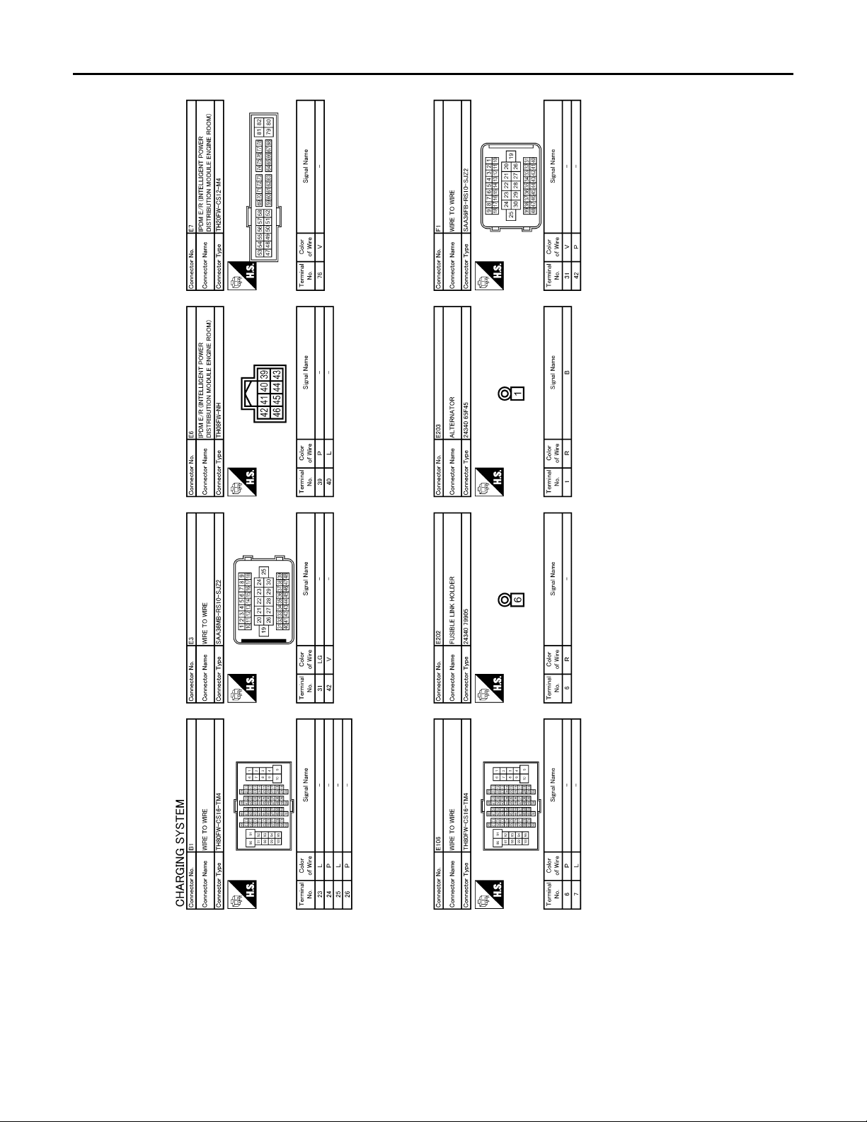
Wiring Diagram — CHARGING SYSTEM — INFOID:0000000000964280
A
B
C
D
E
F
G
H
JCMWA0028G
I
J
K
L
CHG
N
O
P
CHG-15
Page 16
< COMPONENT DIAGNOSIS >
B
Revision: October 2006
2007 G35 Sedan
CHARGING SYSTEM
JCMWA0029G
CHG-16
Page 17

< COMPONENT DIAGNOSIS >
B
Revision: October 2006
2007 G35 Sedan
CHARGING SYSTEM
A
B
C
D
E
F
G
H
I
J
K
L
CHG
N
O
JCMWA0030G
P
CHG-17
Page 18

CHARGING SYSTEM
Revision: October 2006
2007 G35 Sedan
< SYMPTOM DIAGNOSIS >
SYMPTOM DIAGNOSIS
CHARGING SYSTEM
Symptom Table INFOID:0000000000964281
Symptom Reference
Battery discharged
The charge warning lamp does not illuminate when the ignition
switch is set to ON.
The charge warning lamp does not t urn OFF after the engine
starts.
The charging warning lamp turn s ON when i ncr easi ng th e eng i ne
speed.
Refer to CHG-3, "
Work Flow".
CHG-18
Page 19

< PRECAUTION >
Revision: October 2006
2007 G35 Sedan
PRECAUTIONS
PRECAUTION
PRECAUTIONS
Precaution for Supplemental Restraint System (SRS) "AIR BAG" and "SEAT BELT PRE-TENSIONER" INFOID:0000000000964282
The Supplemental Restraint System such as “AIR BAG” and “SEAT BELT PRE-TENSIONER”, used along
with a front seat belt, helps to reduce the risk or severity of injury to the driver and front passenger for certain
types of collision. This system includes seat belt switch inputs and dual stage front air bag modules. The SRS
system uses the seat belt switches to determine the front air bag deployment, and may only deploy one front
air bag, depending on the severity of a collision and whether the front occupants are belted or unbelted.
Information necessary to service the system safely is included in the SRS and SB section of this Service Manual.
WARNING:
• To avoid rendering the SRS inoperative, which could increase the risk of personal injury or death in
the event of a collision which would result in air bag inflation, all maintenance must be performed by
an authorized NISSAN/INFINITI dealer.
• Improper maintenance, including incorrect removal and installation of the SRS, can lead to personal
injury caused by unintentional activation of the system. For removal of Spiral Cable and Air Bag
Module, see the SRS section.
• Do not use electrical test equipment on any circuit related to the SRS unless instructed to in this
Service Manual. SRS wiring harnesses can be identified by yellow and/or orange harnesses or harness connectors.
Precaution for Power Generation Voltage Variable Control System INFOID:0000000000964283
A
B
C
D
E
F
G
H
CAUTION:
For this model, the battery current sensor that is installed to the battery cable at the negative terminal
measures the charging/discharging current of the battery , and perfor ms various controls. If the electrical component or the ground wire is connected directly to the battery terminal, the current other than
that being measured with the battery current sensor is charging to or discharging from the battery.
This condition causes the malfunction of the control, and then the battery discharge may occur. Do
not connect the electrical component or the ground wire directly to the battery terminal.
I
J
K
L
CHG
N
O
P
CHG-19
Page 20

PREPARATION
Revision: October 2006
2007 G35 Sedan
< PREPARATION >
PREPARATION
PREPARATION
Special Service Tool INFOID:0000000000964284
Tool number
(Kent-Moore No.)
Tool name
—
(J-44373 Model MCR620)
Starting/Charging System Tester
SEL403X
Description
Tests starting and charging systems.
For operating instructions, refer to T echnical
Service Bulletin.
Commercial Service Tool INFOID:0000000000964285
Tool name Description
Power tool Loosening bolts, nuts and screws
PIIB1407E
CHG-20
Page 21

CHARGING SYSTEM PRELIMINARY INSPECTION
Revision: October 2006
2007 G35 Sedan
< ON-VEHICLE MAINTENANCE >
ON-VEHICLE MAINTENANCE
CHARGING SYSTEM PRELIMINARY INSPECTION
Inspection Procedure INFOID:0000000000964286
1.CHECK BATTERY TERMINALS CONNECTION
Check if battery terminals are clean and tight.
Is the inspection result normal?
YES >> GO TO 2.
NO >> Repair battery terminals connection.
2.CHECK FUSE
Check for blown fuse and fusible link.
Unit Power source (Power supply terminals) Fuse No.
Alternator Battery (“S” terminal) 32
Combination meter Ignition switch ON (“L” terminal) 4
Is the inspection result normal?
YES >> GO TO 3.
NO >> Be sure to eliminate cause of malfunction before installing new fuse.
3.CHECK “E” TERMINAL CONNECTION
Check if “E” terminal (alternator ground harness) is clean and tight.
Is the inspection result normal?
YES >> GO TO 4.
NO >> Repair “E” terminal connection.
4.CHECK DRIVE BELT TENSION
Check drive belt tension. Refer to EM-12, "
Is the inspection result normal?
YES >> Inspection end.
NO >> Repair as needed.
Checking".
A
B
C
D
E
F
G
H
I
J
K
L
CHG
N
O
P
CHG-21
Page 22

POWER GENERATION VOLTAGE VARIABLE CONTROL SYSTEM OPERATION
Revision: October 2006
2007 G35 Sedan
INSPECTION
< ON-VEHICLE MAINTENANCE >
POWER GENERATION VOLTAGE VARIABLE CONTROL SYSTEM OPERATION INSPECTION
Inspection Procedure INFOID:0000000000964287
CAUTION:
When performing this inspection, always use a charged battery that has completed the battery inspection. (When the charging rate of the battery is low, the response speed of the voltage change will
become slow. This can cause an incorrect inspection.)
1.CHECK ECM (CONSULT-III)
Perform ECM self-diagnosis with CONSULT-III. Refer to EC-113, "
Self
-diagnostic results content
No malfunction detected>> GO TO 2.
Malfunction detected>> Check applicable parts, and repair or replace corresponding parts.
CONSULT-III Function".
2.CHECK OPERATION OF POWER GENERATION VOLTAGE VARIABLE CONTROL SYSTEM
1. Connect CONSUL T-III and start the engine.
2. The selector lever is in “P” or “N” position and all of the electric loads and A/C, etc. are turned OFF.
3. Select “ALTERNATOR DUTY” at “Active Test” of “ENGINE”, and then check the value of “BATTERY
VOLT” monitor when DUTY value of “ALTERNATOR DUTY” is set to 40.0 %.
“BATTERY VOLT”
2 seconds after setting the
DUTY value of “ALTERNATOR DUTY” to 40.0 %
4. Check the value of “BATTERY VOLT” monitor when DUTY value of “ALTERNATOR DUTY” is set to
80.0%.
“BATTERY VOLT”
20 seconds after setting
the DUTY value of “ALTERNATOR DUTY” to 80.0 %
: 12 - 13.6 V
: +0.5 V or more against
the value of “BATTERY
VOLT” monitor when
DUTY value is 40.0 %
Is the measurement value within the specification?
YES >> Inspection end.
NO >> GO TO 3.
3.CHECK IPDM E/R (CONSULT-III)
Perform IPDM E/R self-diagnosis with CONSULT-III. Refer to PCS-12, "
Self
-diagnostic results content
No malfunction detected>> GO TO 4.
Malfunction detected>> Check applicable parts, and repair or replace corresponding parts.
4.CHECK HARNESS BETWEEN ALTERNATOR AND IPDM E/R
1. Turn ignition switch OFF.
2. Disconnect alternator connector and IPDM E/R connector.
3. Check continuity between alternator harness connector and IPDM E/R harness connector.
Alternator harness connector IPDM E/R harness connector
Connector Terminal Connector Terminal
4. Check continuity between alternator harness connector and ground.
CONSULT - III Function (IPDM E/R)".
Continuity
F36 4 E7 76 Existed
CHG-22
Page 23

POWER GENERATION VOLTAGE VARIABLE CONTROL SYSTEM OPERATION
Revision: October 2006
2007 G35 Sedan
INSPECTION
< ON-VEHICLE MAINTENANCE >
Alternator harness connector
Connector Terminal
F36 4 Not existed
Ground
Is the inspection result normal?
YES >> Replace IPDM E/R.
NO >> Repair harness or connector between IPDM E/R and alternator.
Continuity
A
B
C
D
E
F
G
H
I
J
K
L
CHG
N
O
P
CHG-23
Page 24

ALTERNATOR
B
Revision: October 2006
2007 G35 Sedan
< ON-VEHICLE REPAIR >
ON-VEHICLE REPAIR
ALTERNATOR
2WD
2WD : Exploded View INFOID:0000000000964288
REMOVAL
1. “B” terminal nut 2. “B” terminal harness 3. Alternator connector
4. Alternator mounting bolt 5. Alternator stay mounting bolt 6. Alternator stay
7. Alternator
: Engine front
Refer to GI-4, "Components" for symbols in the figure.
DISASSEMBLY
Type: A3TJ1991
JSMIA0006G
CHG-24
Page 25

< ON-VEHICLE REPAIR >
B
Revision: October 2006
2007 G35 Sedan
ALTERNATOR
A
B
C
D
E
F
G
JSMIA0007G
1. Rear bearing 2. Rotor assembly 3. Retainer
4. Front bearing 5. Front bracket assembly 6. Pulley
7. Pulley nut 8. St ator assembly 9. IC voltage regulator assembly
10. Diode assembly 11. Rear bracket assembly 12. Terminal set
13. “B” terminal nut
Refer to GI-4, "
Components" for symbols in the figure.
2WD : Removal and Installation INFOID:0000000000964289
REMOVAL
1. Disconnect the battery cable from the negative terminal.
2. Remove engine front undercover, using power tools.
3. Remove radiator cooling fan assembly. Refer to CO-14, "
4. Remove drive belt. Refer to EM-12, "
Removal and Installation".
5. Disconnect alternator connector (1).
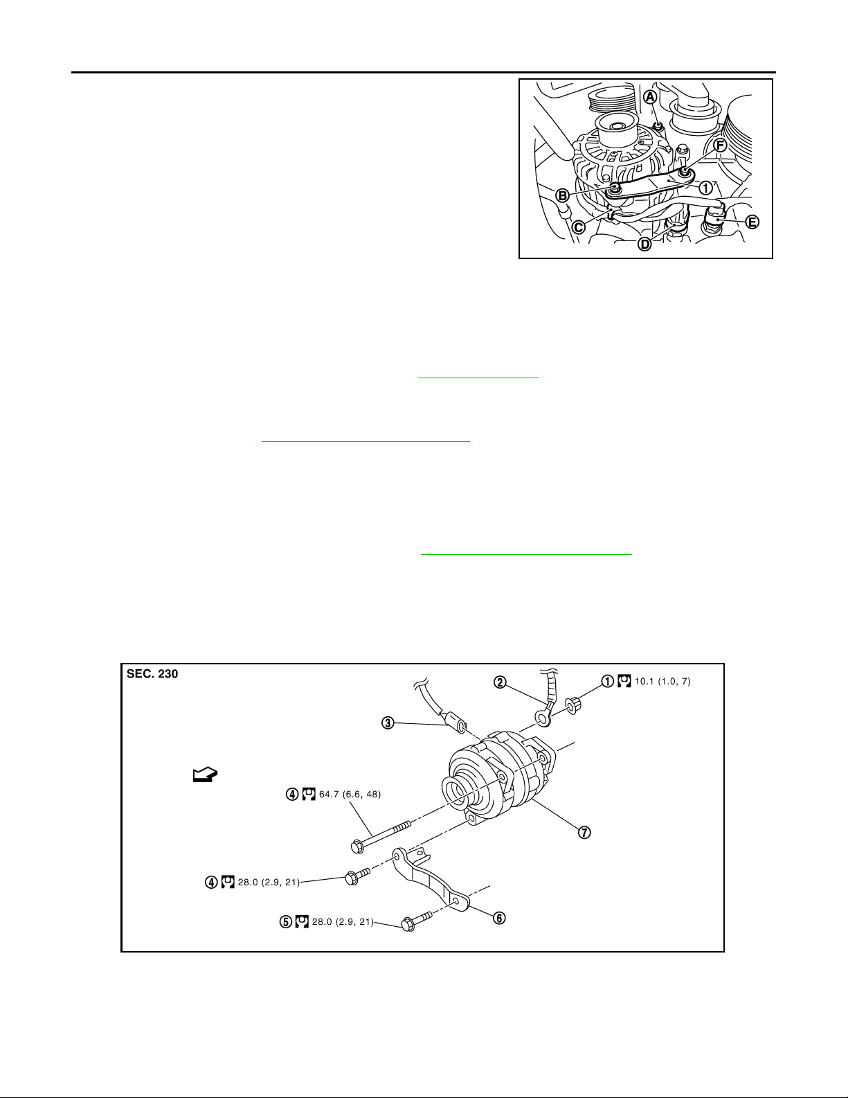
6. Remove “B” terminal nut (2).
7. Remove the harness bracket bolts (A).
Exploded View".
H
I
J
K
L
CHG
N
O
P
SKIB2605J
CHG-25
Page 26
ALTERNATOR
B
Revision: October 2006
2007 G35 Sedan
< ON-VEHICLE REPAIR >
8. Remove oil pressure switch harness clip (C) from alternator stay
(1).
9. Disconnect oil pressure switch connector (D) and oil temperature sensor connector (E).
10. Remove alternator mounting bolt (B) and alternator stay mounting bolt (F) using power tools, then remove alternator stay.
11. Remove alternator mounting bolt (A), using power tools.
JSMIA0012ZZ
12. Remove alternator assembly downward from the vehicle.
INSTALLATION
Install in the reverse order of removal.
CAUTION:
Be sure to tighten “B” terminal nut carefully.
• Install alternator, and check tension of belt. Refer to EM-12, "
• For this model, the power generation voltage variable control system that controls the power generation volt-
age of the alternator has been adopted. Therefore, the power generation voltage variable control system
operation inspection should be performed after replacing the alternator, and then make sure that the system
operates normally. Refer to CHG-22, "
Inspection Procedure".
Checking".
2WD : Inspection INFOID:0000000000964290
ALTERNATOR PULLEY INSPECTION
Perform the following.
• Make sure that alternator pulley does not rattle.
• Make sure that alternator pulley nut is tight. Refer to CHG-24, "
2WD : Exploded View".
AWD
AWD : Exploded View INFOID:0000000000964291
REMOVAL
1. “B” terminal nut 2. “B” terminal harness 3. Alternator connector
4. Alternator mounting bolt 5. Alternator stay mounting bolt 6. Alternator stay
7. Alternator
JSMIA0006G
CHG-26
Page 27

< ON-VEHICLE REPAIR >
B
Revision: October 2006
2007 G35 Sedan
ALTERNATOR
: Engine front
Refer to GI-4, "
Components" for symbols in the figure.
DISASSEMBLY
Type: A3TJ1991
A
B
C
D
E
F
G
H
JSMIA0007G
1. Rear bearing 2. Rotor assembly 3. Retainer
4. Front bearing 5. Front bracket assembly 6. Pulley
7. Pulley nut 8. St ator assembly 9. IC voltage regulator assembly
10. Diode assembly 11. Rear bracket assembly 12. Terminal set
13. “B” terminal nut
Refer to GI-4, "
Components" for symbols in the figure.
AWD : Removal and Installation INFOID:0000000000964292
REMOVAL
1. Disconnect the battery cable from the negative terminal.
2. Remove air cleaner case (RH). Refer to EM-25, "
3. Remove the clip (B) from the harness bracket (1) and “B” terminal harness from the clip (C).
4. Disconnect pressure sensor connector (A).
Exploded View".
I
J
K
L
CHG
N
O
P
5. Remove engine undercover, using power tools.
JSMIA0013ZZ
CHG-27
Page 28

ALTERNATOR
Revision: October 2006
2007 G35 Sedan
< ON-VEHICLE REPAIR >
6. Remove radiator cooling fan assembly. Refer to CO-14, "Exploded View".
7. Remove drive belt. Refer to EM-12, "
8. Remove alternator mounting bolt (B) and alternator stay mounting bolt (C) using power tools, then remove alternator stay (1).
9. Remove alternator mounting bolt (A), using power tools.
10. Pull and turn alternator, and then remove the harness bracket
bolts (A).
11. Disconnect alternator connector (1).
12. Remove “B” terminal nut (2).
Removal and Installation".
JSMIA0014ZZ
SKIB2608J
13. Remove alternator assembly downward from the vehicle.
INSTALLATION
Install in the reverse order of removal.
CAUTION:
Be sure to tighten “B” terminal nut carefully.
• Install alternator, and check tension of belt. Refer to EM-12, "
• For this model, the power generation voltage variable control system that controls the power generation volt-
age of the alternator has been adopted. Therefore, the power generation voltage variable control system
operation inspection should be performed after replacing the alternator, and then make sure that the system
operates normally. Refer to CHG-22, "
Inspection Procedure".
Checking".
AWD : Inspection INFOID:0000000000964293
ALTERNATOR PULLEY INSPECTION
Perform the following.
• Make sure that alternator pulley does not rattle.
• Make sure that alternator pulley nut is tight. Refer to CHG-26, "
AWD : Exploded View".
CHG-28
Page 29

SERVICE DATA AND SPECIFICATIONS (SDS)
Revision: October 2006
2007 G35 Sedan
< SERVICE DATA AND SPECIFICATIONS (SDS)
SERVICE DATA AND SPECIFICATIONS (SDS)
SERVICE DATA AND SPECIFICATIONS (SDS)
Alternator INFOID:0000000000964294
Type
Nominal rating [V - A] 12 -150
Ground polarity Negative
Minimum revolution under no-load (When 13.5 V is ap-
plied)
Hot output current (When 13.5 V is applied) [A/rpm]
Regulated output voltage [V]
Minimum length of brush [mm (in)] More than 5.00 (0.197)
Brush spring pressure [N (g, oz)] 4.1 - 5.3 (418 - 540, 14.8 - 19.1)
Slip ring minimum outer diameter [mm (in)] More than 22.1 (0.870)
Rotor (Field coil) resistance [Ω]1.7 - 2.0
*: Adjustment range of power generation voltage variable control is 11.4 - 15.6 V.
[rpm] Less than 1,300
A3TJ1991
MITSUBISHI make
More than 31/1,300
More than 122/2,500
More than 144/5,000
14.1 - 14.7
*
A
B
C
D
E
F
G
H
I
J
K
L
CHG
N
O
P
CHG-29
 Loading...