

Page 1
NIPPON PRECISION CIRCUITS INC.
NIPPON PRECISION CIRCUITS-1
OVERVIEW
CF5732 Series
Analog clock CMOS IC
The CF5732 series are analog clock driver ICs using
32kHz reference frequency of crystal oscillator. Some
versions in accordance with the combinations of each
motor drive and alarm output characteristics can provide
a wide range of applications for various clock specifications.
The CF5732 series incorporates 4 types of pace adjustment capacitors, which enables to adjust the pace with
bonding options.
FEATURES
- Built-in oscillator circuits(32.678 kHz)
On-chip feed back resistors (Rf, Rd)
Crystal oscillator capacitors (CD, CG)
Additional 4 capacitors for pace adjustment.
- Debounce circuit (AI terminal)
- Single 1.5 V supply
- Available as a die
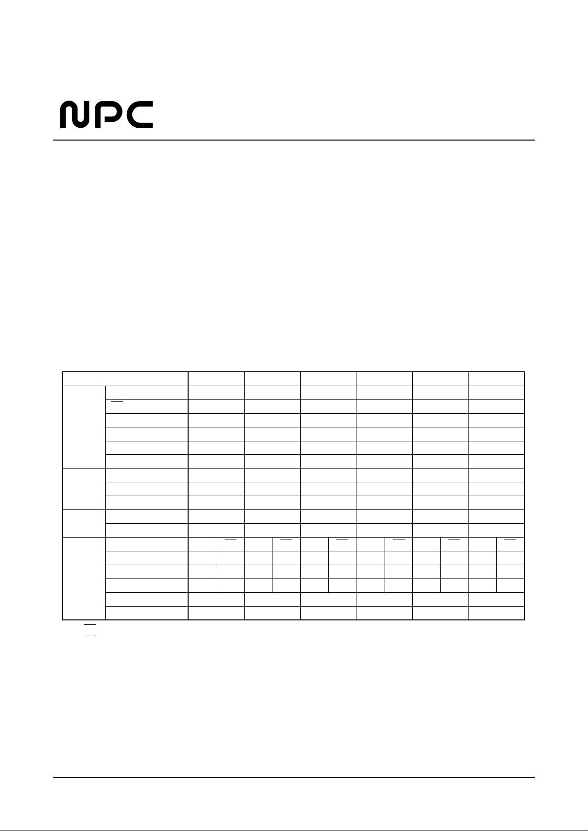
SERIES LINEUP
CF5732EA CF5732FA CF5732GA CF5732HA CF5732JA CF5732KA
Built-in XT terminal C
G(pF) 11.5 11.5 10 11.5 11.5 11.5
Capacitor XT terminal C
D(pF) 29 29 25 29 29 29
C1(pF) 6 6 3666
C2(pF) 7 7 4777
C4(pF) 8 8 5888
C4(pF) 9 9 6999
Motor Active Level - H L H H H
Output Hand Drive Cycle(sec) 0.125 1 1111
Pulse Width(msec) DUTY50% 31.25 31.25 15.6 23.4375 46.875
Alarm Active Level L L LLLL
Input Test Function Yes(1/2V
DD) Yes(1/2VDD) Yes(1/2VDD) Yes(1/2VDD) Yes(1/2VDD) Yes(1/2VDD)
Alarm Terminal AO AO AO AO AO AO AO AO AO AO AO AO
Output Active Level H L(*1) H L(*2) H L(*1) H L(*2) H L(*2) H L(*2)
Fundmental Frequency(Hz) 2048 2048 2048 2048 2048 2048 2048 2048 2048 2048 2048 2048
Modulation Frequency(Hz) 8+1 8+1 8+1 8+1 8+1 8+1 16+116+18+18+18+18+1
I
OH MIN(mA) −1.0 −1.0 −1.0 −1.0 −1.0 −1.0
I
OL MIN(mA) 1.0 1.0 1.0 1.0 1.0 1.0
(*1) AO is the reverse phase of AO, when output is active. (the same phase, when output is inactive)
(*2) AO is complete reverse phase of AO. (even output is inactive.)
Page 2
NIPPON PRECISION CIRCUITS-2
CF5732 Series
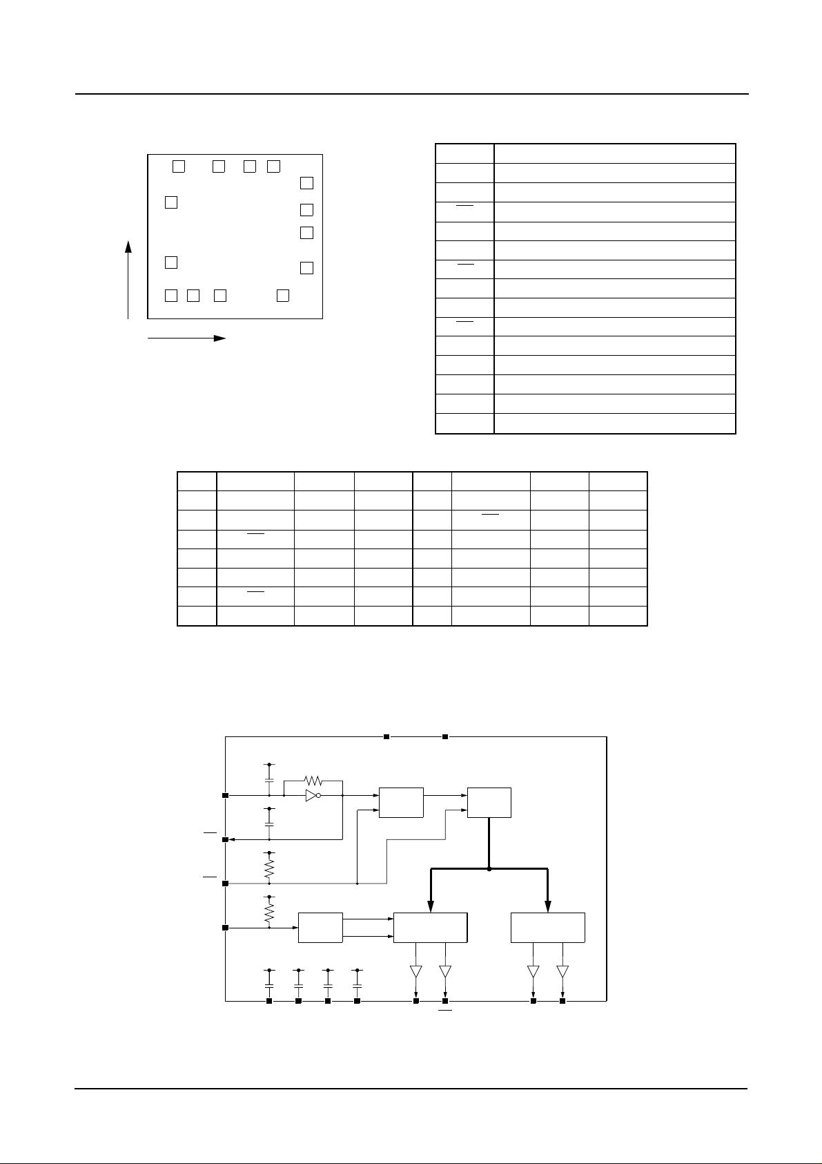
PINOUT
(0, 0)
1234
5
6
78 9
11
X
Y
10
12
13
14
Name
VDD
VSS
TC
AI
AO
AO
OUT2
OUT1
XT
XT
C1
C2
C3
C4
Description
Power supply pin
Ground
Test pin
Alarm Input
Alarm signal Output
Alarm signal Inverting Output
Motor drive output 2
Motor drive output 1
Crystal oscillator connection
Crystal oscillator connection
Supplementary internal capacitor connection 1
Supplementary internal capacitor connection 2
Supplementary internal capacitor connection 3
Supplementary internal capacitor connection 4
Chip size: 1.49×1.40mm
Chip thickness: 300±30µm
Pad size: 100×100µm
Reverse side of chip is VDD.
No Name X Y No Name X Y
1 VDD 1023 1248 8 OUT1 340 151
2 VSS 817 1248 9 XT 567 151
3 TC 553 1248 10 XT 1101 151
4 AI 214 1248 11 C1 1305 382
5 AO 151 943 12 C2 1305 682
6 AO 151 429 13 C3 1305 880
7 OUT2 151 151 14 C4 1305 1105
(Unit: µm)
PIN DESCRIPTION
BLOCK DIAGRAM
4 Stage
Divider
13 Stage
Divider
Alarm
Input
Alarm Output
Control
Mortor Output
Control
VDD
VSS
AO AO OUT1 OUT2
TC
AI
Alarm
Test
XT
CG
CD
XT
C1 C2 C3 C4
Page 3

NIPPON PRECISION CIRCUITS-3
CF5732 Series
ABSOLUTE MAXIMUM RATINGS
ELECTRICAL CHARACTERISTICS
Parameter Symbol Condition Rating Unit
Supply Voltage V
DD - VSS −0.3 to +5.0 V
Input Voltage V
IN VSS ≤ VIN ≤ VDD V
Operating Temperature T
OPR −30 to +70 °C
Storage Temperature T
STG −40 to +125 °C
(VSS= 0V)
Rating
Parameter Symbol Condition MIN TYP MAX Unit
Supply Voltage V
DD 1.1 1.5 2.0 V
Supply Current I
DD No Load(*1) 1.0 3.0 µA
Motor Output Current I
MOT VDD= 1.2V, RL= 200Ω 4.0 mA
Alarm Output Current I
OH AO, AO pin, VOH= 0.75V −1.0 mA
I
OL AO, AO pin, VOL= 0.75V 1.0 mA
Alarm Input Voltage V
IH AI pin VDD−0.2 VDD V
V
IL AI pin VSS VSS+0.2 V
Alarm Input Center Voltage V
IM AI pin 1/2VDD V
Input Resistance R
IN AI pin 5 15 50 kΩ
Oscillator Stability ∆f/f V
DD= 1.1V to 2.0V 0.5 1 PPM/0.1V
Internal Capacitance C
G (*2) GA 10 pF
others 11.5 pF
C
D (*3) GA 25 pF
others 29 pF
(Ta= 25°C, VDD= 1.5V, VSS= 0V, f0= 32.768kHz unless otherwise noted)
(*1) All terminals except for the supply and the crystal oscillators are open.
(*2) C
G is the incorporated capacitance between VDD and XT.
(*3) C
D is the incorporated capacitance between VDD and XT.
Page 4

NIPPON PRECISION CIRCUITS-4
CF5732 Series
FUNCTIONAL DESCRIPTION
Alarm input/output
AO
AO
(*1)
AI
AO
(*2)
1/2VDD (*3)
fPW fCY
(*1) AO is the reverse phase of AO, when output is active. (the same phase, when output is inactive): CF5732EA, GA
(*2) AO is complete reverse phase of AO. (even output is inactive.): CF5732FA, HA, JA, KA
(*3) When AI is held at 1/2 V
DD, the alarm reference, frequency is output at AO and AO.
Input Debouncing Circuit
Setting bouncing delay time prevents the circuit from the
erroneous operation by AI input bouncing (chattering.)
ton ≤ 31.25 msec : The alarm input is ignored
ton ≥ 62.5 msec : The alarm input is accepted
tCH tON
AI
(Active L)
Page 5

NIPPON PRECISION CIRCUITS-5
CF5732 Series
Motor Drive Outputs
Step needle movement
CF5732FA, GA, HA, JA, KA
OUT1
OUT2
tPW
tPW
tCY
1sec
tCY
1sec
OUT1
OUT2
tCY
125msec
tCY
125msec
Continuos needle movement
CF5732EA
Page 6

NIPPON PRECISION CIRCUITS-6
CF5732 Series
NC9121BE 1996 3
NIPPON PRECISION CIRCUITS INC.
NIPPON PRECISION CIRCUITS INC. reserves the right to make changes to the products described in this data sheet in order to
improve the design or performance and to supply the best possible products. Nippon Precision Circuits Inc. assumes no responsibility for
the use of any circuits shown in this data sheet, conveys no license under any patent or other rights, and makes no claim that the circuits
are free from patent infringement. Applications for any devices shown in this data sheet are for illustration only and Nippon Precision
Circuits Inc. makes no claim or warranty that such applications will be suitable for the use specified without further testing or modification. The products described in this data sheet are not intended to use for the apparatus which influence human lives due to the failure or
malfunction of the products. Customers are requested to comply with applicable laws and regulations in effect now and hereinafter, including compliance with export controls on the distribution or dissemination of the products. Customers shall not export, directly or indirectly, any products without first obtaining required licenses and approvals from appropriate government agencies.
NIPPON PRECISION CIRCUITS INC.
4-3, 2-chome Fukuzumi, Koto-ku
Tokyo, 135 -8430, JAPAN
Telephon: 03-3642-6661
Facsimile: 03-3642-6698
 Loading...