

Page 1

CRUISE CONTROL
Revision: 2007 June G37 Coupe
A
B
SECTION CCS
CRUISE CONTROL SYSTEM
CONTENTS
INTELLIGENT CRUISE CONTROL
BASIC INSPECTION ....................................4
DIAGNOSIS AND REPAIR WORKFLOW ..........4
Work Flow .................................................................4
INSPECTION AND ADJUSTMENT ..................... 6
ADDITIONAL SERVICE WHEN REPLACING
CONTROL UNIT ..........................................................
ADDITIONAL SERVICE WHEN REPLACING
CONTROL UNIT : Description ..................................
ADDITIONAL SERVICE WHEN REPLACING
CONTROL UNIT : Special Repair Requirement .......
LASER BEAM AIMING ADJUSTMENT ......................6
LASER BEAM AIMING ADJUSTMENT : Descrip-
tion ............................................................................
LASER BEAM AIMING ADJUSTMENT : Special
Repair Requirement (Preparation) ............................
LASER BEAM AIMING ADJUSTMENT : Special
Repair Requirement (Setting The ICC Target
Board) .......................................................................
LASER BEAM AIMING ADJUSTMENT : Special
Repair Requirement (Laser Beam Aiming Adjust-
ment) .......................................................................
ACTION TEST ...........................................................11
ACTION TEST : Description ...................................11
ACTION TEST : Special Repair Requirement (Ve-
hicle-To-Vehicle Distance Control Mode) ................
ACTION TEST : Special Repair Requirement
(Conventional (Fixed Speed) Cruise Control
Mode) ......................................................................
FUNCTION DIAGNOSIS ..............................15
INTELLIGENT CRUISE CONTROL SYSTEM ....15
System Diagram ......................................................15
System Description .................................................15
Component Parts Location ......................................20
10
11
13
Component Description ...........................................21
DIAGNOSIS SYSTEM (ICC SENSOR INTE-
GRATED UNIT) .................................................
Diagnosis Description ..............................................22
CONSULT-III Function (ICC) ...................................23
COMPONENT DIAGNOSIS .........................27
C1A00 CONTROL UNIT ...................................27
6
6
6
6
7
7
Description ....................... ...... ....... ...... ....... ...... ........27
DTC Logic ................................................................27
Diagnosis Procedure ...............................................27
C1A01 POWER SUPPLY CIRCUIT 1, C1A02
POWER SUPPLY CIRCUIT 2 ...........................
Description ....................... ...... ....... ...... ....... ...... ........28
DTC Logic ................................................................28
Diagnosis Procedure ...............................................28
C1A03 VEHICLE SPEED SENSOR ..................30
Description ....................... ...... ....... ...... ....... ...... ........30
DTC Logic ................................................................30
Diagnosis Procedure ...............................................30
C1A04 ABS/TCS/VDC SYSTEM ......................32
Description ....................... ...... ....... ...... ....... ...... ........32
DTC Logic ................................................................32
Diagnosis Procedure ...............................................32
C1A05 BRAKE SW/STOP LAMP SW ..............34
Description ....................... ...... ....... ...... ....... ...... ........34
DTC Logic ................................................................34
Diagnosis Procedure (A/T Models) ..........................34
Diagnosis Procedure (M/T Models) .........................38
Component Inspection (ICC BRAKE SWITCH) .......42
Component Inspection (STOP LAMP SWITCH) .....43
Component Inspection (ICC CLUTCH SWITCH) ....43
C1A06 OPERATION SW ..................................44
Description ....................... ...... ....... ...... ....... ...... ........44
DTC Logic ................................................................44
22
28
C
D
E
F
G
H
I
J
K
L
M
N
CCS
P
CCS-1
Page 2

Diagnosis Procedure .............................................. 44
Revision: 2007 June G37 Coupe
Component Inspection ............................................ 46
C1A12 LASER BEAM OFF CENTER ............... 47
Description ....................... .......................... ............. 47
DTC Logic ............................................................... 47
Diagnosis Procedure .............................................. 47
C1A13 STOP LAMP RELAY .............................48
Description ....................... .......................... ............. 48
DTC Logic ............................................................... 48
Diagnosis Procedure .............................................. 48
Component Inspection ............................................ 54
C1A14 ECM ....................................................... 55
Description ....................... .......................... ............. 55
DTC Logic ............................................................... 55
Diagnosis Procedure .............................................. 55
C1A15 GEAR POSITION ................................... 57
Description ....................... .......................... ............. 57
DTC Logic ............................................................... 57
Diagnosis Procedure .............................................. 57
C1A16 RADAR STAIN ......................................59
Description ....................... .......................... ............. 59
DTC Logic ............................................................... 59
Diagnosis Procedure .............................................. 59
C1A18 LASER AIMING INCMP ........................ 61
Description ....................... .......................... ............. 61
DTC Logic ............................................................... 61
Diagnosis Procedure .............................................. 61
C1A21 UNIT HIGH TEMP .................................. 62
Description ....................... .......................... ............. 62
DTC Logic ............................................................... 62
Diagnosis Procedure .............................................. 62
C1A24 NP RANGE ............................................63
Description ....................... .......................... ............. 63
DTC Logic ............................................................... 63
Diagnosis Procedure .............................................. 63
C1A26 ECD MODE MALFUNCTION ................ 65
Description ....................... .......................... ............. 65
DTC Logic ............................................................... 65
Diagnosis Procedure .............................................. 65
Diagnosis Procedure ..... ... .......................................70
U0121 VDC CAN 2 ............................................ 71
Description ..............................................................71
DTC Logic ........... ... ... .... ... ... ....................................71
Diagnosis Procedure ..... ... .......................................71
U0401 ECM CAN 1 ............................................ 73
Description ..............................................................73
DTC Logic ........... ... ... .... ... ... ....................................73
Diagnosis Procedure ..... ... .......................................73
U0402 TCM CAN 1 ............................................ 75
Description ..............................................................75
DTC Logic ........... ... ... .... ... ... ....................................75
Diagnosis Procedure ..... ... .......................................75
U0415 VDC CAN 1 ............................................ 77
Description ..............................................................77
DTC Logic ........... ... ... .... ... ... ....................................77
Diagnosis Procedure ..... ... .......................................77
U1000 CAN COMM CIRCUIT ............................ 79
Description ..............................................................79
DTC Logic ........... ... ... .... ... ... ....................................79
Diagnosis Procedure .......................... ....................79
U1010 CONTROL UNIT (CAN) ......................... 80
Description ..............................................................80
DTC Logic ........... ... ... .... ... ... ....................................80
Diagnosis Procedure ..... ... .......................................80
POWER SUPPLY AND GROUND CIRCUIT ..... 81
Diagnosis Procedure ..... ... .......................................81
PARK/NEUTRAL POSITION SWITCH (M/T) .... 82
Description ..............................................................82
Component Function Check ................................... 82
Diagnosis Procedure ..... ... .......................................82
Component Inspection ............................................83
ECU DIAGNOSIS ....................................... 85
ICC SENSOR INTEGRATED UNIT ................... 85
Reference Value .....................................................85
Wiring Diagram - ICC SYSTEM - ............................88
Fail Safe ........................................... ... .................... 92
DTC Index ........................................... ... ................. 92
C1A27 ECD POWER SUPPLY CIRCUIT .......... 67
Description ....................... .......................... ............. 67
DTC Logic ............................................................... 67
Diagnosis Procedure .............................................. 67
SYMPTOM DIAGNOSIS ............................ 94
INTELLIGENT CRUISE CONTROL SYSTEM
SYMPTOMS .......................................................
Symptom Table .......................................................94
C1A33 CAN TRANSMISSION ERROR ............. 69
Description ....................... .......................... ............. 69
DTC Logic ............................................................... 69
Diagnosis Procedure .............................................. 69
MAIN SWITCH DOES NOT TURN ON, MAIN
SWITCH DOES NOT TURN OFF ......................
Description ..............................................................95
Diagnosis Procedure ..... ... .......................................95
C1A34 COMMAND ERROR .............................. 70
Description ....................... .......................... ............. 70
DTC Logic ............................................................... 70
ICC SYSTEM CANNOT BE SET (MAIN
SWITCH TURNS ON/OFF) ................................
CCS-2
94
95
97
Page 3

Description ..............................................................
Revision: 2007 June G37 Coupe
Diagnosis Procedure ........................... ... .................97
97
Description ....................... ...... ....... ...... ....... ...... ......106
Diagnosis Procedure .............................................106
A
ICC STEERING SWITCH (OTHER THAN
MAIN SWITCH) DOES NOT FUNCTION ...........
Description ..............................................................99
Diagnosis Procedure ........................... ... .................99
99
ICC SYSTEM DOES NOT CANCEL WHEN A/
T SELECTOR LEVER SETS ON "N" ..............
Description ............................................................100
Diagnosis Procedure ........................... ... ...............100
100
CHIME DOES NOT SOUND .............................102
Description ............................................................102
Diagnosis Procedure ........................... ... ...............102
DRIVING FORCE IS HUNTING ........................104
Description ............................................................104
Diagnosis Procedure ........................... ... ...............104
ICC SYSTEM FREQUENTLY CANNOT DETECT THE VEHICLE AHEAD/ DETECTION
ZONE IS SHORT ..............................................
Description ............................................................105
Diagnosis Procedure ........................... ... ...............105
105
THE SYSTEM DOES NOT DETECT THE VE-
HICLE AHEAD AT ALL ....................................
106
NORMAL OPERATING CONDITION .............107
Description ....................... ...... ....... ...... ....... ...... ......107
PRECAUTION ............................................109
PRECAUTIONS ...............................................109
Precaution for Supplemental Restrain t Syste m
(SRS) "AIR BAG" and "SEAT BELT PRE-TEN-
SIONER" ...............................................................
ICC System Service ........................................... ...109
109
PREPARATION .........................................110
PREPARATION ...............................................110
Special Service Tools ............................................110
ON-VEHICLE REPAIR ............................... 111
ICC SENSOR INTEGRATED UNIT .................111
Exploded View .......................................................111
Removal and Installation .......................................111
Inspection and Adjustment ....................................112
ICC STEERING SWITCH ................................ 113
Exploded View .......................................................113
Removal and Installation .......................................113
B
C
D
E
F
G
H
I
J
K
L
M
N
CCS
P
CCS-3
Page 4
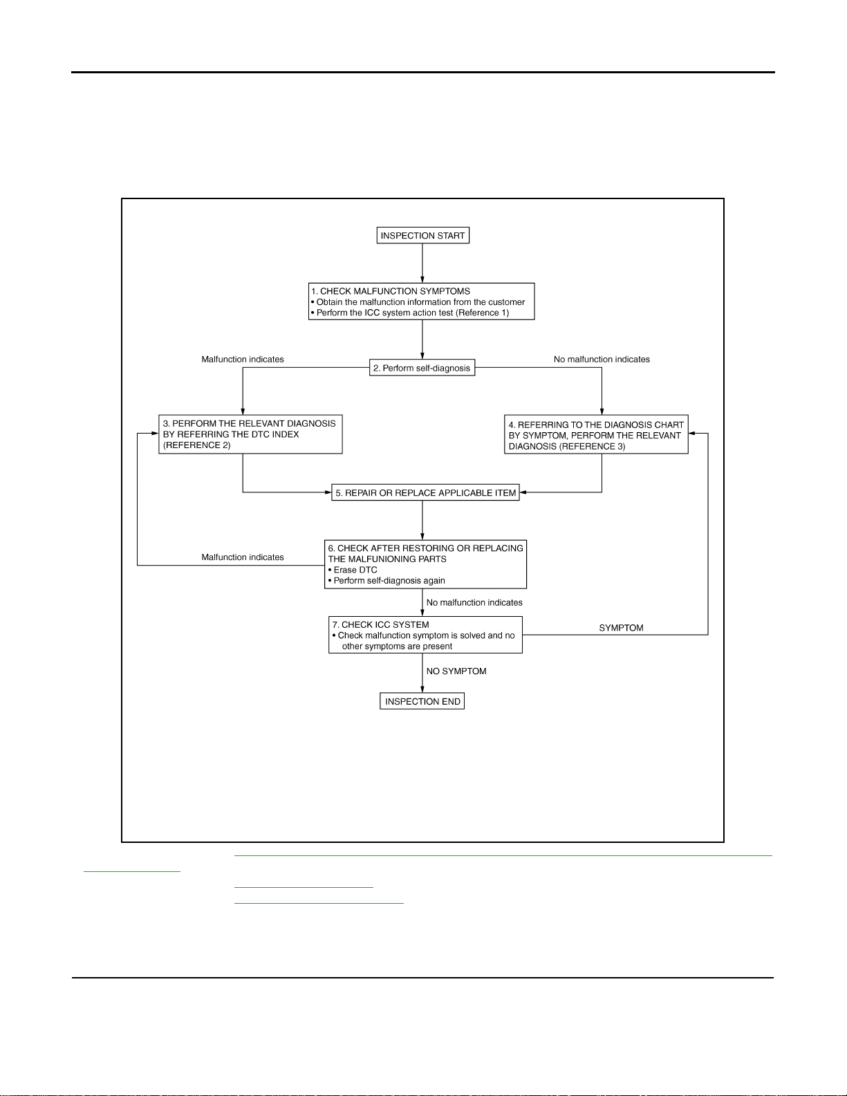
DIAGNOSIS AND REPAIR WORKFLOW
B
Revision: 2007 June G37 Coupe
< BASIC INSPECTION >
[INTELLIGENT CRUISE CONTROL]
BASIC INSPECTION
DIAGNOSIS AND REPAIR WORKFLOW
Work Flow INFOID:0000000001606855
OVERALL SEQUENCE
JSOIA0021G
• Reference 1··· Refer to CCS-11, "ACTION TEST : Special Repair Requirement (Vehicle-To-Vehicle Distance
Control Mode)".
• Reference 2··· Refer to CCS-92, "
• Reference 3··· Refer to CCS-94, "
DTC Index".
Symptom Table".
DETAILED FLOW
1.CHECK SYMPTOM
Check the malfunction symptoms by performing the following items.
• Obtain the malfunction information (conditions and environment when the malfunction occurred) from the
customer.
CCS-4
Page 5

DIAGNOSIS AND REPAIR WORKFLOW
Revision: 2007 June G37 Coupe
< BASIC INSPECTION >
• Perform the ICC system action test to check the ICC system operation status. Refer to CCS-11, "ACTION
TEST : Special Repair Requirement (Vehicle-To-Vehicle Distance Control Mode)".
>> GO TO 2.
[INTELLIGENT CRUISE CONTROL]
2.PERFORM SELF-DIAGNOSIS OF ICC SENSOR INTEGRA TED UNIT
1. Perform self-diagnosis of ICC sensor integrated unit.
2. Check if DTC is detected.
Is any DTC detected?
YES >> GO TO 3.
NO >> GO TO 4.
3.CHECK SELF-DIAGNOSIS RESULTS
A
B
C
D
1. Check the DTC detected in the self-diagnosis results.
2. Perform the relevant diagnosis by referring to the DTC index. Refer to CCS-92, "
NOTE:
If “CAN COMM CIRCUIT [U1000]” (DTC 100) is displayed, start with the diagnosis for the CAN communication system. Refer to CCS-79, "
>> GO TO 5.
Diagnosis Procedure".
DTC Index".
4.DIAGNOSIS BY SYMPTOM
Referring to the diagnosis chart by symptom, perform the relevant diagnosis. Refer to CCS-94, "
Table".
>> GO TO 5.
Symptom
5.REPAIR OR REPLACE APPLICABLE ITEM
Repair or replace applicable item.
>> GO TO 6.
6.CHECK AFTER REPAIRING OR REPLACING THE APPLICABLE ITEM
1. Erase DTC.
2. Perform the self-diagnosis for the ICC sensor integrated unit again after repairing or replacing the applica-
ble item.
3. Check if DTC is detected.
Is any DTC detected?
YES >> GO TO 3.
NO >> GO TO 7.
7.CHECK ICC SYSTEM
E
F
G
H
I
J
K
L
M
Test the ICC system for normal operation to see if the malfunction symptom is solved and no other symptoms
are present.
No symptoms?
YES >> INSPECTION END
NO >> GO TO 4.
CCS-5
N
CCS
P
Page 6

INSPECTION AND ADJUSTMENT
Revision: 2007 June G37 Coupe
< BASIC INSPECTION >
[INTELLIGENT CRUISE CONTROL]
INSPECTION AND ADJUSTMENT
ADDITIONAL SERVICE WHEN REPLACING CONTROL UNIT
ADDITIONAL SERVICE WHEN REPLACING CONTROL UNIT : Description
INFOID:0000000001606856
Always perform the laser beam aiming adjustment after replacing the ICC sensor integrated unit. In addition,
test the ICC system operations to see if it functions normally.
ADDITIONAL SERVICE WHEN REPLACING CONTROL UNIT : Special Repair Requirement
INFOID:0000000001606857
1.LASER BEAM AIMING ADJUSTMENT
Adjust laser beam aiming. Refer to CCS-7, "
ment (Preparation)".
>> GO TO 2.
LASER BEAM AIMING ADJUSTMENT : Special Repair Require-
2.ICC SYSTEM ACTION TEST
1. Perform the ICC system operation test. Refer to CCS-11, "
(Vehicle-To-Vehicle Distance Control Mode)".
2. Check that the ICC system operates normally.
>> INSPECTION END
LASER BEAM AIMING ADJUSTMENT
LASER BEAM AIMING ADJUSTMENT : Description INFOID:0000000001606858
OUTLINE OF LASER BEAM AIMING ADJUSTMENT
Adjust the laser beam aiming every time the ICC sensor integrated unit is removed or installed.
1. Set up the ICC target board [SST: KV99110100 (J-45718)].
NOTE:
The location of the ICC sensor integrated unit (1) differs according to the vehicle grade. So the ICC target
board setting position varies accordingly.
ACTION TEST : Special Repair Requirement
JSOIA0076ZZ
A : Leather grade type B : Sport grade type
2. Adjust the sensor following the procedure on CONSUL T-III. (Turn manually the screw for up-down position
adjustment. ICC sensor integrated unit automatically adjust the right-left position.)
CAUTIONARY POINTS FOR LASER BEAM AIMING
CAUTION:
• Adjust laser beam aiming at a horizontal place as far as 12 m (39 ft) forward the vehicle can be seen.
• Adjust laser beam aiming 5 seconds after starting engine.
• Never view ICC sensor integrated unit body window directly during laser beam aiming adjustment.
• Follow the CONSULT-III when adjusting the laser beam aiming (laser beam aiming adjustment can-
not be operated without CONSULT-III).
• Never ride on vehicle during laser beam aiming adjustment.
• Idle and turn headlamps OFF during laser beam aiming adjustment.
CCS-6
Page 7

INSPECTION AND ADJUSTMENT
Revision: 2007 June G37 Coupe
< BASIC INSPECTION >
[INTELLIGENT CRUISE CONTROL]
LASER BEAM AIMING ADJUSTMENT : Special Repair Requirement (Preparation)
INFOID:0000000001606859
1.PREPARATION OF BEFOR LASER BEAM AIMING ADJUSTMENT
1. Adjust the tire pressure to the specified value.
2. See that there is no load in the vehicle.
3. Coolant, engine oil filled up to correct level and full fuel tank.
4. Shift the selector lever to the “P” range (A/T) or the shift knob to the neutral position (M/T), and release the
parking brake.
5. Clean the ICC sensor integrated unit body window with a soft cloth.
A
B
C
>> Go to CCS-7, "
LASER BEAM AIMING ADJUSTMENT : Special Repair Requirement (Setting The
ICC Target Board)".
LASER BEAM AIMING ADJUSTMENT : Sp ecial Repair Requirement (Setting The ICC Target Board)
Accurate ICC target board setting is required for the laser beam aiming adjustment.
NOTE:
ICC system does not function normally if laser beam aiming is not accurate.
INFOID:0000000001606860
1.ADJUSTING HEIGHT OF THE ICC TARGET BOARD
1. Attach a triangle scale (2) at a position 42 mm (1.65 in) (H)
below the center (A) of the ICC target board (1).
3: Adjust nut
b: 90°
JSOIA0014ZZ
2. Adjust the height of the ICC target board with aligning the upside
tip of the triangle scale (1) with the center of laser beam axis (A).
D
E
F
G
H
I
J
K
2 : ICC sensor integrated unit
NOTE:
• The center of laser beam axis (A) is located at 38 mm (1.5 in) (W)
from the left side and 22 mm (0.87 in) (H) from the top of the ICC
sensor integrated unit from a front view of vehicle.
CCS-7
JSOIA0015ZZ
JSOIA0022ZZ
L
M
N
CCS
P
Page 8

INSPECTION AND ADJUSTMENT
Revision: 2007 June G37 Coupe
< BASIC INSPECTION >
• To identify the center of laser beam axis (A) easily, prepare a piece
of paper (B) cut to the size of 38 mm (1.5 in) (W) ×22 mm (0.87 in)
(H) and attach it on the upper left point of the ICC sensor integrated unit (1).
>> GO TO 2.
[INTELLIGENT CRUISE CONTROL]
2.ADJUSTING THE RIGHT-LEFT POSITION OF THE ICC TARGET BOARD
1. Attach a ruler (1) or equivalent tool with a length of 450 mm
(17.72 in) or more to the back face of the ICC target board center (A) in the leftward direction.
JSOIA0023ZZ
JSOIA0024ZZ
2. Suspend a weight from a string (1) attached to its end at the
point (B) rightward from the ICC target board center (A).
W [mm (in)]
Leather grade type : 404 (15.91)
Sport grade type : 247 (9.72)
NOTE:
To learn how to identify the vehicle grade, refer to CCS-6,
"LASER BEAM AIMING ADJUSTMENT : Description".
JSOIA0016ZZ
>> GO TO 3.
3.SETTING THE ICC TARGET BOARD
1. Suspend a thread with weight on tip to splice the center of the front and rear bumpers. Then, mark the
center point on the ground as each weight points.
2. Link the front and rear bumpers center points marked on the ground, and mark a point 3.9 m (12.8 ft) posi-
tion ahead of the front bumper, on the extended line of the previous link line of the bumper center points.
Then, adjust the position of the ICC target board so that the weight come on the top of the marked point
[3.9 m (12.8 ft) position ahead of the front bumper] and face to the vehicle.
3. Adjust the position of the ICC target board (1) so that the
extended line (A) that links the center of the rear window glass
(the center of the rear window defogger pattern) (B) and the center of the windshield (the setting part of the room mirror) (C)
align with the weight suspended (2) from the ICC target board.
CCS-8
JSOIA0025ZZ
Page 9

INSPECTION AND ADJUSTMENT
Revision: 2007 June G37 Coupe
< BASIC INSPECTION >
4. Remove the thread suspended to the right side of ICC target board and suspend a thread with weight on
tip on the center of the ICC target board. Then mark the point of weight on the ground.
5. Pivot the edge of the ICC target board 25° (a) to either side.
NOTE:
Approx. 90 mm (3.54 in) (b) shift rates the 25° (a) movement.
1 : ICC target board
2 : String with a weight
C : ICC target board center marking position
>> GO TO 4.
[INTELLIGENT CRUISE CONTROL]
JSOIA0026ZZ
4.CHECKING THE ICC TARGET BOARD INSTALLATION POSITION
Check that the ICC target board (1) is located as shown in the figure.
A
B
C
D
E
F
G
1. ICC target board 2. ICC sensor integrated unit 3. Vehicle
B. Vehicle center L
404 mm (15.91 in) (Leather grade type)
W.
247 mm (9.72 in) (Sport grade type)
a. 25°
1. 4.0 m (13.0 ft)
NOTE:
The distance between center of laser beam axis and ICC target board is 4 m (13.0 ft).
>> GO TO 5.
5.CHECKING THE ICC TARGET BOARD INSTALLATION AREA
Do not place anything in the space shown in the figure (view from top).
JSOIA0017ZZ
H
I
J
K
L
M
N
CCS
JSOIA0027ZZ
1. ICC target board 2. ICC sensor integrated unit
L
1. 6.5 m (21.3 ft) L2. 4.0 m (13.0 ft) W. 3.5 m (11.5 ft)
NOTE:
CCS-9
P
Page 10
INSPECTION AND ADJUSTMENT
Revision: 2007 June G37 Coupe
< BASIC INSPECTION >
In case the space shown in the figure is not available, make a space by covering the side of the ICC target
board with a 1400 mm (4.6 ft)-size frosted black board or black cloth.
[INTELLIGENT CRUISE CONTROL]
>> Go to CCS-10, "
Beam Aiming Adjustment)".
LASER BEAM AIMING ADJUSTMENT : Special Repair Requirement (Laser
LASER BEAM AIMING ADJUSTMENT : Special Repair Requirement (Laser Beam Aiming Adjustment)
CAUTION:
Never view ICC sensor integrated unit body window directly during laser beam aiming adjustment.
NOTE:
Complete all necessary work for laser beam adjustment until the adjustment completes as shown in the procedure. If the procedure does not complete, the ICC system is inoperable.
INFOID:0000000001606861
1.SET CONSULT-III TO THE LASER BEAM AIMING ADJUSTMENT MODE
1. Connect CONSULT-III and select “Work Support” of “ICC”.
2. Select “LASER BEAM ADJUST” after the “Work Support” screen is displayed.
3. Touch “START” after the “LASER BEAM ADJUST” screen is displayed.
NOTE:
If the adjustment screen does not appear on the CONSULT-III screen in 10 seconds. After touching
“LASER BEAM ADJUST” screen, the following causes may be considered:
• ICC target is not set accurately.
• There is not enough space beside the ICC target.
• The range of laser beam aiming exceeds for improper installation position.
- Deformation of vehicle body.
- Deformation of unit.
- Deformation of bracket.
• The area is not suitable for the adjustment work.
• ICC sensor integrated unit body window is not clean.
• The ICC system warning lamp illuminates.
>> GO TO 2.
2.LASER BEAM AIMING ADJUSTMENT
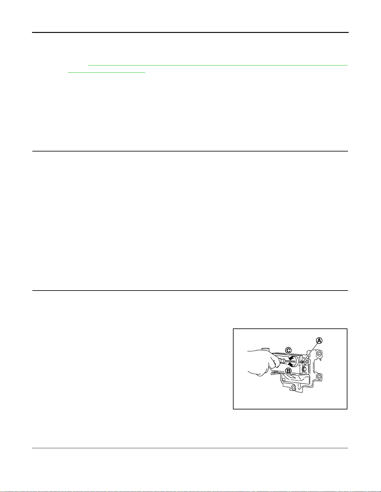
1. After the CONSULT-III displays “ADJUST THE VERTICAL OF LASER BEAM AIMING” turn the up-down
direction adjusting screw until “U/D CORRECT” value is set in the range of ±4.
NOTE:
• Turn the screw slowly. The value change on display is slower than actual movement of the ICC sensor
integrated unit. Wait for 2 seconds every time the screw is turned half a rotation.
• Turning the screw (A) clockwise to laser beam is downward
(B) and counterclockwise to laser beam is upward (C).
JSOIA0018ZZ
>> GO TO 3.
3.LASER BEAM AIMING CONFIRMATION
1. When “U/D CORRECT” value indicates ±4, confirm that the margin of value remains within ±4 at least for
2 seconds with no equipment or hand touching the ICC sensor integrated unit.
2. When “COMPLETED THE VERTICAL AIMING OF LASER BEAM” appears on screen, touch “END”.
CCS-10
Page 11
INSPECTION AND ADJUSTMENT
Revision: 2007 June G37 Coupe
< BASIC INSPECTION >
NOTE:
Be sure that the margin of “U/D CORRECT” is within ±4 with ICC sensor integrated unit is untouched.
3. Confirm that “ADJUSTING AUTOMATIC HORIZONTAL LASER BEAM AIMING” is on screen and wait for
a while (maximum: 10 seconds).
4. Confirm that “NORMALLY COMPLETED” is displayed on CONSULT-III and close the aiming adjustment
procedure by touching “END”.
NOTE:
Complete all the procedures once “LASER BEAM ADJUST” mode is entered in CONSULT-III. When the
procedure is discontinued, the ICC system is inoperable.
>> LASER BEAM AIMING ADJUSTMENT END
[INTELLIGENT CRUISE CONTROL]
ACTION TEST
ACTION TEST : Description INFOID:0000000001606862
Always perform the ICC system action test to check that the ICC system operates normally after replacing the
ICC sensor integrated unit or repairing any ICC system malfunction.
A
B
C
D
E
ACTION TEST : Special Repair Requirement (Vehicle-To-Vehicle Distance Control Mode)
NOTE:
• When there is no vehicle ahead, drive at the set speed steadily.
• When there is a vehicle ahead, control to maintain distance from the vehicle ahead, watching its speed.
INFOID:0000000001606863
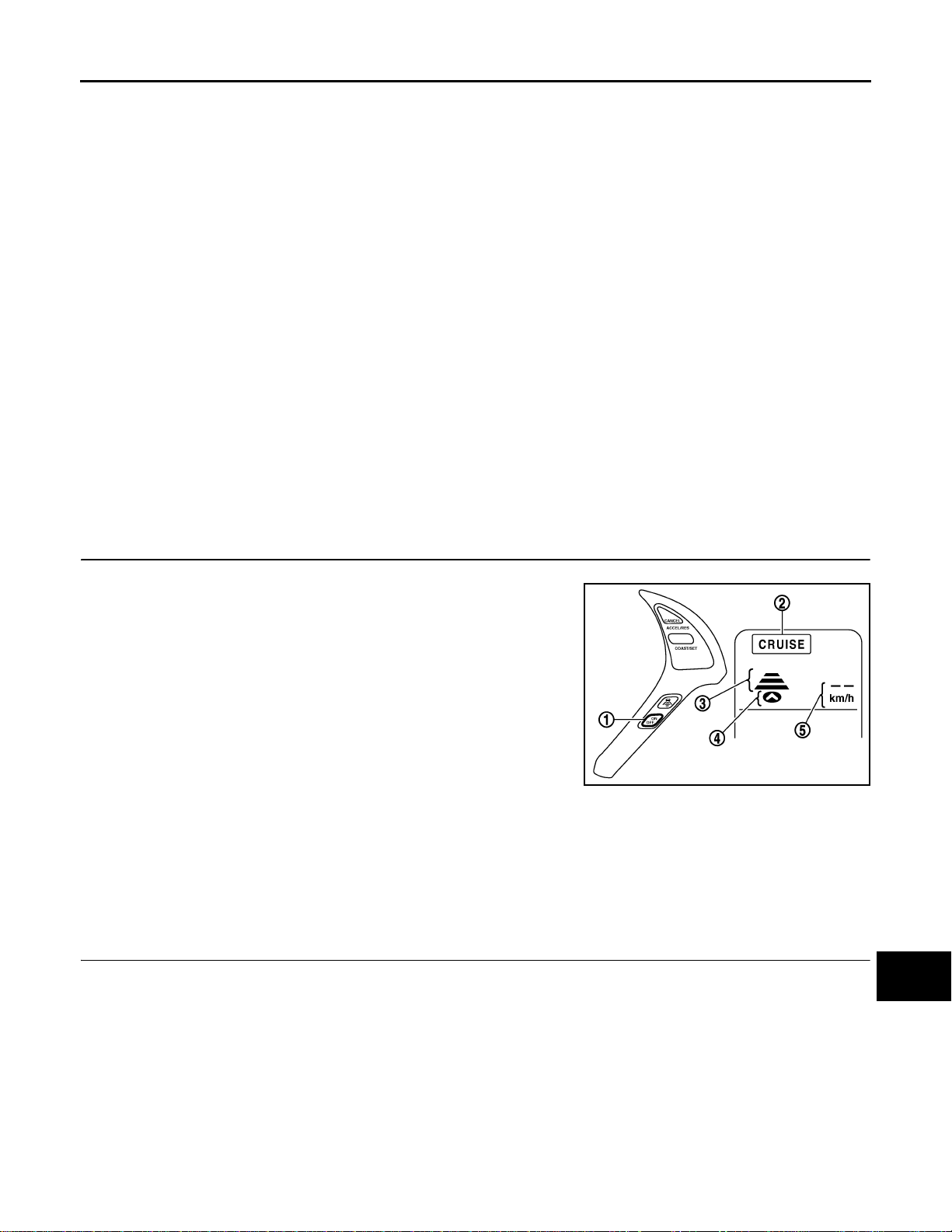
1.CHECK FOR MAIN SWITCH
1. Start engine.
2. Press the MAIN switch (1) for less than 1.5 seconds.
3. Check the ICC system display in the combination meter to check
that the vehicle-to-vehicle distance control mode is ready for
activation.
ICC system display status
“CRUISE” indicator lamp (2) : ON
Set distance indicator (3) : Long mode
Own vehicle indicator (4) : ON
Set vehicle speed indicator (5) :
4. Press the MAIN switch, and check that the ICC system display turns off when the ICC system is deactivated.
5. Check that the ICC system display turns off after starting the engine again.
“——”
“km/h (MPH)”
JSOIA0004ZZ
F
G
H
I
J
K
L
M
>> GO TO 2.
2.CHECK FOR DISTANCE SWITCH
1. Start engine.
2. Press the MAIN switch for less than 1.5 seconds.
3. Press the DISTANCE switch.
CCS-11
N
CCS
P
Page 12

INSPECTION AND ADJUSTMENT
B
Revision: 2007 June G37 Coupe
< BASIC INSPECTION >
4. Check if the set distance indicator changes display in order of: (Long)→(Middle)→(Short).
NOTE:
The set distance indicator shows (Long) immediately after the engine starts.
[INTELLIGENT CRUISE CONTROL]
JSOIA0005G
>> GO TO 3.
3.CHECK FOR RESUME/ACCELERATE, SET/COAST, CANCEL SWITCHES
1. Check if RESUME/ACCELERATE, SET/COAST, CANCEL switches are operated smoothly.
2. Check if switches come up as hand is released from the switches.
>> GO TO 4.
4.SET CHECKING
1. Start engine.
2. Press the MAIN switch for less than 1.5 seconds.
3. Drive the vehicle between 40 km/h (25 MPH) and 144 km/h (90 MPH).
4. Push down the SET/COAST switch.
5. Confirm that the desired speed is set as hand is released from the SET/COAST switch.
NOTE:
The set vehicle speed is displayed on the ICC system display.
>> GO TO 5.
5.CHECK FOR INCREASE OF CRUISING SPEED
1. Set vehicle-to-vehicle distance control mode at desired speed.
2. Check if the set speed increases by 1 km/h (1 MPH) as RESUME/ACCELERATE switch is pushed up.
NOTE:
The maximum set speed of the vehicle-to-vehicle distance control mode is 144 km/h (90 MPH).
>> GO TO 6.
6.CHECK FOR DECREASE OF CRUISING SPEED
1. Set vehicle-to-vehicle distance control mode at desired speed.
2. Check if the set speed decreases by 1 km/h (1 MPH) as SET/COAST switch is pushed down.
NOTE:
• Vehicle-to-vehicle distance control mode is automatically cancelled when the driving speed lowers to 32 km/
h (20 MPH) due to the deceleration of the vehicle ahead.
• The minimum set speed of the vehicle-to-vehicle distance control mode is 40 km/h (25 MPH).
>> GO TO 7.
CCS-12
Page 13

< BASIC INSPECTION >
Revision: 2007 June G37 Coupe
INSPECTION AND ADJUSTMENT
[INTELLIGENT CRUISE CONTROL]
7.CHECK FOR CANCELLATION OF VEHICLE-TO-VEHICLE DISTANCE CONTROL MODE
Check that the vehicle-to-vehicle distance control mode is canceled when performing the following operations.
• When the brake pedal is depressed after the system is turned ON.
• When the clutch pedal is depressed after the system is turned ON (M/T).
• When the A/T selector lever is shifted to the “N” range (A/T).
• When the MAIN switch is turned OFF.
• When CANCEL switch is operated.
>> GO TO 8.
8.CHECK FOR RESTORING SPEED THAT IS SET BY VEHICLE-TO-VEHICLE DISTANCE CONTROL
MODE BEFORE CANCELLATION
Check that the vehicle restores the previous speed kept before the system deactivation when performing the
following operations.
• Cancel the system by depressing the brake pedal. Then check if the speed before cancellation is restored
when pushing up RESUME/ACCELERA TE switch with 40 km/h (25 MPH) or above.
• Depress the clutch pedal to cancel the system. Then release the clutch pedal (shift knob at any of the 1st to
6th gear positions). Check that the vehicle restores the previous speed kept before the system deactivation
when pushing up the RESUME/ACCELERA TE switch whil e the vehicle speed is 40 km/h (25 MPH) or more.
• Shift the A/T shift selector lever to the “N” range to cancel the system. Then shift the A/T shift selector lever
back to the “D” range. Check that the vehicle restores the previous speed kept before the system deactivation when pushing up the RESUME/ACCELERATE switch while the vehicle speed is 40 km/h (25 MPH) or
more (A/T).
• Press the CANCEL switch to cancel the system. Then check that the vehicle restores the previous speed
kept before the system deactivation when pushing up the RESUME/ACCELERATE switch while the vehicle
speed is 40 km/h (25 MPH) or more.
A
B
C
D
E
F
G
H
>> OPERATION INSPECTION COMPLETION
ACTION TEST : Special Repair Requirement (Conventional (Fixed Speed) Cruise Control Mode) INFOID:0000000001606864
1.CHECK FOR MAIN SWITCH
1. Start engine.
2. Press the MAIN switch (1) for more than 1.5 seconds.
3. Check that the ICC system display in the combination meter
indicates that the conventional (fixed speed) cruise control mode
is ready for activation.
ICC system display status
“CRUISE” indicator lamp (2) : ON
4. Press the MAIN switch, and check that the ICC system display
turns off when the ICC system is deactivated.
5. Check that the ICC system display turns off after starting the
engine again.
>> GO TO 2.
JSOIA0006ZZ
2.CHECK FOR RESUME/ACCELERATE, SET/COAST, CANCEL SWITCHES
1. Check if RESUME/ACCELERATE, SET/COAST, CANCEL switches are operated smoothly.
2. Check if switches come up as hand is released from the switches.
I
J
K
L
M
N
CCS
P
>> GO TO 3.
3.SET CHECKING
1. Start engine.
CCS-13
Page 14

INSPECTION AND ADJUSTMENT
Revision: 2007 June G37 Coupe
< BASIC INSPECTION >
2. Press the MAIN switch for more than 1.5 seconds.
3. Drive the vehicle between 40 km/h (25 MPH) and 144 km/h (90 MPH).
4. Push down the SET/COAST switch.
5. Confirm that the desired speed is set as hand is released from the SET/COAST switch.
NOTE:
• The set vehicle speed is not displayed on the ICC system display.
• The SET indicator in the ICC system display illuminates.
>> GO TO 4.
[INTELLIGENT CRUISE CONTROL]
4.CHECK FOR INCREASE OF CRUISING SPEED
1. Set the conventional (fixed speed) cruise control mode at desired speed.
2. Check if the set speed increases by 1.6 km/h (1 MPH) as RESUME/ACCELERATE switch is pushed up.
NOTE:
• If the RESUME/ACCELERATE switch is kept pushing up during cruise control driving, the vehicle speed
increases until the switch is released.
• The maximum set speed is 144 km/h (90 MPH).
>> GO TO 5.
5.CHECK FOR DECREASE OF CRUISING SPEED
1. Set the conventional (fixed speed) cruise control mode at desired speed.
2. Check if the set speed decreases by 1.6 km/h (1 MPH) as SET/COAST switch is pushed down.
NOTE:
• Conventional (fixed speed) cruise control mode is automatically cancelled when the driving speed lowers to
32 km/h (20 MPH).
• The lowest set speed is 40 km/h (25 MPH).
>> GO TO 6.
6.CHECK FOR CANCELLATION OF CONVENTIONAL (FIXED SPEED) CRUISE CONTROL MODE
Check that the CONVENTIONAL (FIXED SPEED) CRUISE CONTROL MODE is canceled when performing
the following operations.
• When the brake pedal is depressed after the system is turned ON.
• When the clutch pedal is depressed after the system is turned ON (M/T).
• When the A/T selector lever is shifted to the “N” range (A/T).
• When the MAIN switch is turned OFF.
• When CANCEL switch is operated.
>> GO TO 7.
7.CHECK FOR RESTORING SPEED THAT IS SET BY CONVENTIONAL (FIXED SPEED) CURISE CON-
TROL MODE BEFORE CANCELLATION
Check that the vehicle restores the previous speed kept before the system deactivation when performing the
following operations.
• Cancel the system by depressing the brake pedal. Then check if the speed before cancellation is restored
when pushing up RESUME/ACCELERATE switch with 40 km/h (25 MPH) or above.
• Depress the clutch pedal to cancel the system. Then release the clutch pedal (shift knob at any of the 1st to
6th gear positions). Check that the vehicle restores the previous speed kept before the system deactivation
when pushing up the RESUME/ACCELERA TE switch while the vehicle speed is 40 km/h (25 MPH) or more.
• Shift the A/T shift selector lever to the “N” range to cancel the system. Then shift the A/T shift selector lever
back to the “D” range. Check that the vehicle restores the previous speed kept before the system deactivation when pushing up the RESUME/ACCELERATE switch while the vehicle speed is 40 km/h (25 MPH) or
more (A/T).
• Press the CANCEL switch to cancel the system. Then check that the vehicle restores the previous speed
kept before the system deactivation when pushing up the RESUME/ACCELERATE switch while the vehicle
speed is 40 km/h (25 MPH) or more.
>> OPERATION INSPECTION COMPLETION
CCS-14
Page 15

INTELLIGENT CRUISE CONTROL SYSTEM
B
Revision: 2007 June G37 Coupe
< FUNCTION DIAGNOSIS >
[INTELLIGENT CRUISE CONTROL]
FUNCTION DIAGNOSIS
INTELLIGENT CRUISE CONTROL SYSTEM
System Diagram INFOID:0000000001606865
A
B
C
D
E
F
G
H
JSOIA0077G
System Description INFOID:0000000001606866
• The Intelligent Cruise Control (ICC) system automatically maintains a selected distance from the vehicle
ahead according to that vehicle's speed, or at the set speed, if the road ahead is clear.
• The ICC function has two cruise control modes and brake assist (with preview function).
• To activate or deactivate the ICC system and set the vehicle speed and vehicle-to-vehicle distance, use the
ICC steering switch.
• The operation status of the ICC system is indicated on the ICC system display of the combination meter.
VEHICLE-TO-VEHICLE DISTANCE CONTROL MODE
• Vehicle-to-vehicle distance control mode, the driver can maintain the same speed as other vehicles without
the constant need to adjust the set speed as the driver would with a normal cruise control system.
• The system is intended to enhance the operation of the vehicle when following the vehicle traveling in the
same lane and direction.
• If the ICC sensor integrated unit detects a slower moving vehicle ahead, the system will reduce speed so
that the vehicle ahead can be followed at the selected distance.
• The system automatically controls the throttle and applies the brakes (up to 25% of vehicle braking power) if
necessary.
• The detection range of the sensor is approximately 390 ft (120 m) ahead.
• Refer to Owner's Manual for Intelligent Cruise Control System operating instructions.
CONVENTIONAL (FIXED SPEED) CRUISE CONTROL MODE
• Conventional (fixed speed) cruise control mode is cruising at preset speeds.
• Refer to Owner's Manual for Intelligent Cruise Control System operating instructions.
I
J
K
L
M
N
CCS
P
BRAKE ASSIST (WITH PREVIEW FUNCTION)
• When the force applied to brake pedal exceeds a certain level, the Brake Assist is activated and generates a
greater braking force than that of a conventional brake booster even with light pedal force.
CCS-15
Page 16

INTELLIGENT CRUISE CONTROL SYSTEM
Revision: 2007 June G37 Coupe
< FUNCTION DIAGNOSIS >
• When the Preview Function identifies the need to apply the sudden brake by sensing the vehicle ahead in
the same lane and the distance and relative speed from it, it applies the brake pre-pressure before driver
depresses the brake pedal and improves brake response by reducing its free play.
• Refer to Owner's Manual for BRAKE ASSIST (WITH PREVIEW FUNCTION) operating instructions.
ICC STEERING SWITCH
ICC system is operated by MAIN switch and four control switches, all mounted on the steering wheel.
[INTELLIGENT CRUISE CONTROL]
JSOIA0010ZZ
1. CANCEL switch 2. RESUME/ACCELERATE switch 3. SET/COAST switch
4. DISTANCE switch 5. MAIN switch
NOTE:
The on board self-diagnosis function of the ICC system can be started with the RESUME/ACCELERATE
switch and SET/COAST switch. Refer to CCS-22, "
Diagnosis Description".
In Vehicle-To-Vehicle Distance Control Mode
No. Switch name Description
1 CANCEL switch Deactivates system without erasing set speed.
2 RESUME/ACCELERATE switch Resumes set speed or increases speed incrementally.
3 SET/COAST switch Sets desired cruise speed or reduces speed incrementally.
4 DISTANCE switch Changes the following distance from: Long, Middle, Short.
5 MAIN switch Master switch to activate the system (Press for less than 1.5 seconds).
In Conventional (Fixed Speed) Cruise Control Mode
No. Switch name Description
1 CANCEL switch Deactivates system without erasing set speed.
2 RESUME/ACCELERATE switch Resumes set speed or increases speed incrementally.
3 SET/COAST switch Sets desired cruise speed or reduces speed incrementally.
4 DISTANCE switch Ineffective in this mode.
5 MAIN switch Master switch to activate the system (Press for more than 1.5 seconds).
ICC SYSTEM DISPLAY
CCS-16
Page 17

INTELLIGENT CRUISE CONTROL SYSTEM
Revision: 2007 June G37 Coupe
< FUNCTION DIAGNOSIS >
The multi information display (1) and ICC system warning lamp (2) in
the combination meter indicate the operation status of the ICC system.
NOTE:
When the on board self-diagnosis is run, ICC system DTC(s), if any,
are displayed in the set vehicle speed indicator (3). Refer to CCS-22,
"Diagnosis Description".
In Vehicle-To-Vehicle Distance Control Mode
[INTELLIGENT CRUISE CONTROL]
A
B
C
JSOIA0020ZZ
D
E
F
No. Display items Description
ICC system warning lamp
1
(CRUISE warning lamp)
2 MAIN switch indicator Indicates that the MAIN switch is ON (ICC system ON).
3 Vehic le ahead detection indicator Indicates whether it detects a vehicle ahead.
4 Set distance indicator Indicates the selected distance between vehicles set with the DISTANCE switch.
5 Own vehicle indicator Indicates the base vehicle.
6 Set vehicle speed indicator Indicates the set vehicle speed.
This indicates that an abnormal condition is present in the ICC system.
In Conventional (Fixed Speed) Cruise Control Mode
JSOIA0011ZZ
JSOIA0012ZZ
G
H
I
J
K
L
M
N
No. Display items Description
ICC system warning lamp
1
(CRUISE warning lamp)
2 MAIN switch indicator Indicates that the MAIN switch is ON (ICC system ON).
3 SET switch indicator Indicates that the set conventional (fixed speed) cruise control mode is controlled.
This indicates that an abnormal condition is present in the ICC system.
ICC SENSOR INTEGRATED UNIT INPUT/OUTPUT SIGNAL ITEM
Input Signal Items
CCS-17
CCS
P
Page 18

INTELLIGENT CRUISE CONTROL SYSTEM
Revision: 2007 June G37 Coupe
< FUNCTION DIAGNOSIS >
Transmission unit Signal name Description
Accelerator pedal position signal
ICC steering
switch signal
ECM
*2
TCM
ABS actuator and
electric unit (control unit)
BCM Front wiper request signal
*1: M/T models
*2: A/T models
ICC brake switch signal
Stop lamp switch signal
Closed throttle position signal
Engine speed signal
ICC clutch switch signal
Park/neutral position switch signal
Shift position signal
Output shaft revolution signal
Current gear position signal
Vehicle speed signal
MAIN switch signal
SET/COAST switch
signal
CANCEL switch sig-
nal
RESUME/ACCEL-
ERATE switch signal
DISTANCE switch
signal
*1
*1
ICC sensor integrated unit receives acc elerator pedal position signal
from ECM with CAN communication.
ICC sensor integrated unit receives ICC steering switch signal from
ECM with CAN communication.
ICC sensor integrated unit receives ICC brake switch signal from
ECM with CAN communication.
ICC sensor integrated unit receives stop lamp switch signal from
ECM with CAN communication.
ICC sensor integrated unit receives closed throttle position signal
from ECM with CAN communication.
ICC sensor integrated unit receives engine speed signal from ECM
with CAN communication.
ICC sensor integrated unit receives ICC clutch switch signal from
ECM with CAN communication.
ICC sensor integrated unit receives park/neutral position switch signal from ECM with CAN communication.
ICC sensor integrated unit receives shift position signal from TCM
with CAN communication.
ICC sensor integrated unit receives A/T vehicle speed sensor signal
(output shaft revolution signal) from TCM with CAN communication.
ICC sensor integrated unit receives cu rrent gear position signal from
TCM with CAN communication.
ICC sensor integrated unit receives vehicle speed signal (wheel
speed) from ABS actuator and electric unit (control unit) with CAN
communication.
ICC sensor integrated unit receives front wiper request signal from
BCM with CAN communication.
[INTELLIGENT CRUISE CONTROL]
Output Signal Items
CCS-18
Page 19
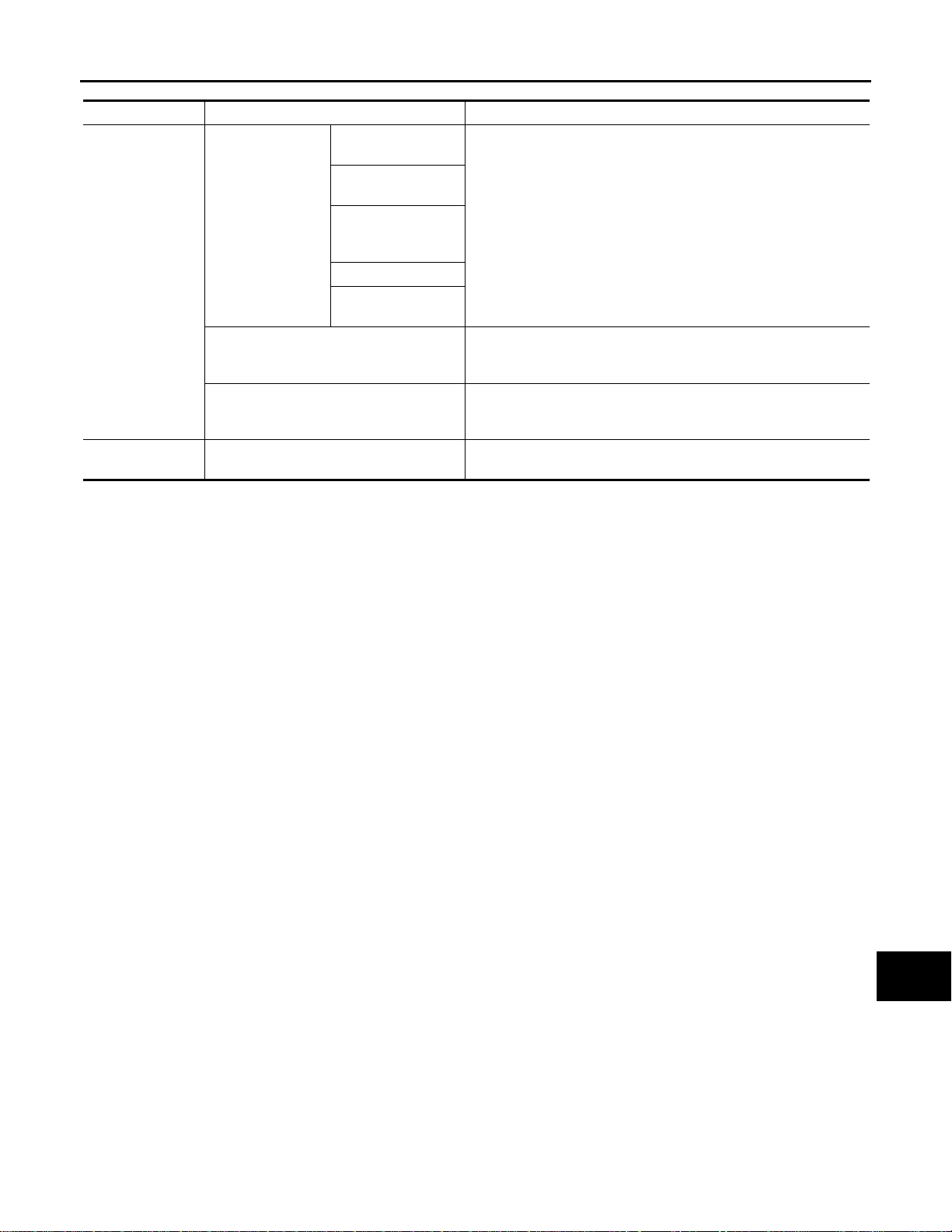
INTELLIGENT CRUISE CONTROL SYSTEM
Revision: 2007 June G37 Coupe
< FUNCTION DIAGNOSIS >
[INTELLIGENT CRUISE CONTROL]
Reception unit Signal name Description
CRUISE indicator
signal
Own vehicle indicator signal
ICC sensor integrated unit transmits ICC system display signal to
combination meter (through unified meter and A/C amp.) with CAN
communication.
ICC sensor integrated unit transmits ICC system warning lamp signal to combination meter (through unified meter and A/C amp.) with
CAN communication.
ICC sensor integrated unit transmits buzzer output signal to combination meter (through unified meter and A/C amp.) with CAN communication.
ICC sensor integrated unit output stop lamp drive signal to ICC
brake hold relay.
Combination
meter (through
unified meter and
A/C amp.)
ICC brake hold relay
ICC system display
signal
ICC system warning lamp signal
Buzzer output signal
ICC brake hold relay drive signal
Vehicle ahead detection indicator signal
SET indicator signal
Set distance indica-
tor signal
A
B
C
D
E
F
G
H
I
J
K
L
M
N
CCS
P
CCS-19
Page 20

INTELLIGENT CRUISE CONTROL SYSTEM
B
Revision: 2007 June G37 Coupe
< FUNCTION DIAGNOSIS >
[INTELLIGENT CRUISE CONTROL]
Component Parts Location
INFOID:0000000001606867
JSOIA0078G
1. ICC system display 2. Buzzer 3. ICC steering switch
4. ECM 5. ICC sensor integrated unit 6. ICC brake hold relay
7. ICC brake switch 8. Stop lamp sw itch 9. ICC clutch switch
10. ABS actuator and electric unit (control unit)
CCS-20
Page 21

INTELLIGENT CRUISE CONTROL SYSTEM
Revision: 2007 June G37 Coupe
< FUNCTION DIAGNOSIS >
A. In combination meter B. Back of combination mete r C. Steering wheel RH
D. Instru ment passenger lower cover
removed
G. Brake pedal H. Clutch pedal
: Vehicle front
E. Front bumper LH F. Engine room LH
[INTELLIGENT CRUISE CONTROL]
Component Description INFOID:0000000001606868
×: Applicable
Vehicle-to-
Component
ICC sensor integrated unit ×××Refer to CCS-27, "
ECM ×××Refer to CCS-55, "
ABS actuator and electric
unit (control unit)
BCM ×
TCM ×× Refer to CCS-75, "
Unified meter and A/C amp. ×××
Combination meter ×××
ICC brake switch ×××
Stop lamp switch ×××
ICC brake hold relay ×××Refer to CCS-48, "
ICC clutch switch ××
vehicle
distance
control mode
×××Refer to CCS-32, "
Conventional
(Fixed speed)
cruise
control mode
Brake assist
(With preview
function)
Description
Description".
Description".
Description".
Transmits front wiper request signal to ICC sensor integrated unit through CAN communication.
Description".
Receives the ICC system display signal, ICC warnin g
lamp signal and ICC warning buzzer sig nal from the ICC
sensor integrated unit with CAN communi cation. Transmits the data to the co mbination meter with communication line.
Using the signals received from the unified meter A/C
amp. with communication line, performs the following
operations.
• Displays the ICC system operation status according
to the ICC system display signal.
• Illuminates the ICC warning lamp according to the
ICC warning lamp signal.
• Operates the buzzer according to the ICC warning
buzzer signal.
Refer to CCS-34, "
Transmits operating signal to ECM when depressing
clutch pedal. ICC sensor integrated unit cancels cruise
system at driver's clutch operation.
Description".
Description".
A
B
C
D
E
F
G
H
I
J
K
L
M
CCS-21
N
CCS
P
Page 22

DIAGNOSIS SYSTEM (ICC SENSOR INTEGRATED UNIT)
B
B
Revision: 2007 June G37 Coupe
< FUNCTION DIAGNOSIS >
[INTELLIGENT CRUISE CONTROL]
DIAGNOSIS SYSTEM (ICC SENSOR INTEGRATED UNIT)
Diagnosis Description INFOID:0000000001606869
The ICC system includes the on board self-diagnosis function that allows the technician to check for any trouble codes on the ICC system display by operating the ICC steering switch.
ON BAOAD SELF-DIAGNOSIS SYSTEM DIAGRAM
JSOIA0009G
ON BOARD SELF-DIAGNOSIS OPERETION PROCEDURE
1. Turn ignition switch OFF.
2. Start engine.
3. From 5 seconds through 15 seconds after start engine, press
RESUME/ACCELERATE switch 5 times, and SET/COAST
switch 5 times.
NOTE:
• Never turn the MAIN switch ON.
• When operation above is not completed from 5 seconds
through 15 seconds, start again from above go to 1.
PKIB8371E
4. When the on board self-diagnosis starts up, the ICC system display shows DTC No. (1) at the set vehicle
speed indicator. Refer to CCS-92, "
DTC Index".
JSOIA0008G
NOTE:
• DTC will disappear after 5 minutes.
• When more than one malfunction is detected, a maximum of 3 code numbers can be stored; the latest
malfunction will be displayed first.
WHEN ON BOARD SELF-DIAGNOSIS WILL NOT START UP
CCS-22
Page 23

DIAGNOSIS SYSTEM (ICC SENSOR INTEGRATED UNIT)
Revision: 2007 June G37 Coupe
< FUNCTION DIAGNOSIS >
If the on board self-diagnosis does not start up, check the following items.
Assumed abnormal point Inspection item
Combination meter malfunction .
Combination meter system.
ICC steering switch malfunction.
Harness malfunction between ICC stee ring switch and ECM.
ECM malfunction.
ICC sensor integrated unit malfunction.
Unified meter and A/C amp. malfunction.
Communication error of the combinat ion
meter and the unified meter and A/C amp.
Check that the self-diagnosis function of the combination
meter starts up. Refer to MWI-35, "
Inspect the unified meter and A/C amp. power an d gro und
circuits. Refer to MWI-50, "
AMP. : Diagnosis Procedure".
Start up the self-diagnosis of the unified meter and A/C
amp. and check the self-diagnosis results. Refer to MWI-
100, "DTC Index".
Perform the inspection for DTC “OPERATION SW CIR
[C1A06]” (DTC 6). Refer to CCS-44, "
dure".
• Inspect the ICC sensor integrated unit power and ground
• Perform the self-diagnosis for the ICC sensor integrated
[INTELLIGENT CRUISE CONTROL]
circuits. Refer to CCS-81, "
unit with CONSULT-III, and check the diagnosis results.
Refer to CCS-92, "
Diagnosis Description".
UNIFIED METER AND A/C
Diagnosis Proce-
Diagnosis Procedure"
DTC Index".
A
B
C
D
E
F
ERASING ON BOARD SELF-DIAGNOSIS
1. Stop the vehicle and turn ignition switch OFF.
2. Start engine and start on board self-diagnosis.
3. During on board self-diagnosis, press CANCEL switch 5 times,
and DISTANCE switch 5 times in this order.
NOTE:
• Press them within 10 seconds after pressing CANCEL switch
at first.
• When operation is not completed within 10 seconds, start
again from step 2 above.
4. DTC 55 will be shown.
NOTE:
PKIB8373E
DTC of an existing malfunction will not be erased.
5. Turn ignition switch OFF to exit the diagnosis.
CONSULT-III Function (ICC) INFOID:0000000001606870
DESCRIPTION
CONSULT-III can display each diagnostic item using the diagnostic test modes shown following.
Test mode Function
Work Support
Self Diagnostic Result Displays malfunctioning system memorized in ICC sensor integrated unit.
Data Monitor Displays real-time input/output data of ICC sensor integrated unit.
Active Test Enables operation check of electrical loads by sending driving signal to them.
ECU Identification Displays part number of ICC sensor integrated unit.
• Monitors aiming direction to facilitate laser beam aiming operation.
• Indicates causes of automatic cancellation of the ICC system.
G
H
I
J
K
L
M
N
CCS
WORK SUPPORT
Work support item Function
CAUSE OF AUTO-CANCEL Indicates causes of automatic cancellation of the ICC system.
Outputs laser beam, calculates dislocation of the beam, and indicates adjustment direction.
LASER BEAM ADJUST
For the adjustment procedure , refer to CCS-7, "
cial Repair Requirement (Preparation)".
LASER BEAM AIMING ADJUSTMENT : Spe-
CCS-23
P
Page 24

DIAGNOSIS SYSTEM (ICC SENSOR INTEGRATED UNIT)
Revision: 2007 June G37 Coupe
< FUNCTION DIAGNOSIS >
Cause of Auto-Cancel Display Item List
Vehicle-to-vehi-
Cause of cancellation
OPERATING WIPER × Windshield wipers were operated at HI or LO speed operation.
OPERATING ABS × ABS function was operated.
OPERATING TCS ××TCS function was operated.
OPERATING VDC ××VDC function was operated.
OPE SW VOLT CIRC ××Outside the standard control switch input voltage was detected.
ECM CIRCUIT ××ECM did not permit ICC operation.
LASER SUN BEAM ×
LASER TEMP × Temperature around ICC sensor integrated unit became low.
OP SW DOUBLE TOUCH ××ICC steering switches were pressed at the same time.
WHL SPD ELEC NOISE ××Wheel speed sensor signal caught electromagnetic noise.
VDC/TCS OFF SW × VDC OFF switch was pressed.
WHEEL SPD UNMATCH ××Wheel speed became different from A/T vehicle speed.
TIRE SLIP ××Wheel slipped.
IGN LOW VOLT ××Power supply voltage became low.
SNOW MODE SW × Snow mode switch was pressed.
VHCL SPD DOWN ××Vehicle speed becomes 32 km/h (20 MPH) and under.
VHCL SPD UNMATCH ××Vehicle speed becomes unusual.
CAN COMM EEROR ××
ABS/TCS/VDC CIRC ××An abnormal condition occurs in ABC/TCS/VDC sys tem
ECD CIRCUIT × An abno rma l co nd itio n oc cu rs in ECD sys tem
ENG SPEED DOWN ××Engine speed became extremely low while controlling ICC system
ASCD VHCL SPD DTAC × Vehicle speed is detached from set vehicle speed
ASCD DOUBLE COMD × Cancel switch and opera tio n sw itc h are detected simultaneously
NO RECORD ××—
cle distance
control mode
Conventional
(fixed speed)
cruise control
mode
Intense light such as sunlight entered ICC sensor integrated unit
light sensing part.
ICC sensor integrated unit received an abnormal signal with CAN
communication
• Last five cancel (system cancel) causes are displayed.
• “CAUSE OF AUTO-CANCEL” displays times of ignition switch ON/OFF up to 254 maximum. 254 is kept
though the number exceeds 254. The number returns to 0 when detecting the same cancellation causes.
[INTELLIGENT CRUISE CONTROL]
×: Applicable
Description
SELF DIAGNOSTIC RESULT
For details, refer to CCS-92, "DTC Index".
NOTE:
“DTC RESULTS” and “TIME” are indicated on “Self Diagnostic Result”. “TIME” is used as a reference data of
diagnosis. It shows when malfunction is detected.
“TIME” shows the following.
• 0: malfunction is detected at present (from malfunction detection to ignition switch OFF).
CAN communication ([U1000], [U1010])
• 1 ~ 39: Displays when it is normal at present and finds malfunction in the past. It increases like
0→1→2...38→39 after returning to the normal condition whenever IGN OFF→ON. If it is over 39, it is fixed to
39 until the self-diagnostic results are erased. It returns to 0 when malfunction is detected again in the process.
Other than CAN communication (other than [U1000], [U1010])
• 1 ~ 49: Displays when it is normal at present and finds malfunction in the past. It increases like
0→1→2...48→49 after returning to the normal condition whenever IGN OFF→ON. If it is over 49, it is fixed to
49 until the self-diagnostic results are erased. It returns to 0 when malfunction is detected again in the process.
CCS-24
Page 25

DIAGNOSIS SYSTEM (ICC SENSOR INTEGRATED UNIT)
Revision: 2007 June G37 Coupe
< FUNCTION DIAGNOSIS >
DATA MONITOR
Monitored Item [unit]
VHCL SPEED SE
[km/h] or [mph]
SET VHCL SPD
[km/h] or [mph]
THRTL OPENING
[%]
THRTL SENSOR
[deg]
SET DISTANCE
[SHOR/MID/LONG]
MAIN SW
[On/Off]
SET/COAST SW
[On/Off]
CANCEL SW
[On/Off]
RESUME/ACC SW
[On/Off]
DISTANCE SW
[On/Off]
CRUISE OPE
[On/Off]
BRAKE SW
[On/Off]
STOP LAMP SW
[On/Off]
CRUISE LAMP
[On/Off]
CLUTCH SW SIG
[On/Off]
NP SW SIG
[On/Off]
STP LMP DRIVE
[On/Off]
PWR SUP MONI
[V]
IDLE SW
[On/Off]
OWN VHCL
[On/Off]
VHCL AHEAD
[On/Off]
ICC WARNING
[On/Off]
BUZZER O/P
[On/Off]
MAIN
SIGNALS
××
××Indicates set vehicle speed memorized in ICC sensor integrated unit.
××
××
××Indicates set distance memorized in ICC sensor integrated unit.
××
××
××
××
××Indicates whether controlling or not (ON means “controlling”).
××
××
××Ind icate s [On/Off] status of MAIN switch indicator lamp output.
××
××
××Indicates [On/Off] status of ICC brake hold relay drive output.
××Indicates IGN voltage input by ICC sensor integrated unit.
[INTELLIGENT CRUISE CONTROL]
SELECTION
FROM
MENU
Indicates vehicle speed calculated from ICC sensor integrated unit through
CAN communication [ABS actuator and electric unit (control unit) transmits
vehicle speed signal (wheel speed) through CAN communication].
Indicates throttle positio n read f rom ICC sens or inte grated uni t thro ugh CAN
communication (ECM transmits accelerator pedal position signal through
CAN communication).
NOTE:
This item is displayed, but cannot monitor.
Indicates [On/Off] status as judged from ICC steering switch signal (ECM
transmits ICC steering sw itch signal through CAN communication).
Indicates [On/Off] status as judged from ICC steering switch signal (ECM
transmits ICC steering sw itch signal through CAN communication).
Indicates [On/Off] status as judged from ICC steering switch signal (ECM
transmits ICC steering sw itch signal through CAN communication).
Indicates [On/Off] status as judged from ICC steering switch signal (ECM
transmits ICC steering sw itch signal through CAN communication).
×
×
× Indicates [On/Off] status of own vehicle indicator output.
× Indicates [On/Off] status of vehicle ahead detection indicator output.
× Indicates [On/Off] status of ICC system warning lamp output.
× Indicates [On/Off] status of ICC warning chime output.
Indicates [On/Off] status as judged from ICC steering switch signal (ECM
transmits ICC steering sw itch signal through CAN communication).
Indicates [On/Off] status as judged from ICC brake switch signal (ECM transmits ICC brake switch signal through CAN communication).
Indicates [On/Off] status as judged from stop lamp switch signal (ECM transmits stop lamp switch signal through CAN communication).
Indicates [On/Off] status as judged from ICC clutch switch signal (ECM transmits ICC clutch switch signal through CAN communication).
Indicates [On/Off] status as judged from park/neutral position switch signal
(ECM transmits park/neutral position switch signal through CAN communication).
Indicates [On/Off] status of idle switch read from ICC sensor integrated unit
through CAN communication (ECM transmits On/Off status through CAN
communication).
Description
×: Applicable
A
B
C
D
E
F
G
H
I
J
K
L
M
N
CCS
P
CCS-25
Page 26

DIAGNOSIS SYSTEM (ICC SENSOR INTEGRATED UNIT)
Revision: 2007 June G37 Coupe
< FUNCTION DIAGNOSIS >
[INTELLIGENT CRUISE CONTROL]
Monitored Item [unit]
ENGINE RPM
[rpm]
WIPER SW
[OFF/LOW/HIGH]
YAW R ATE
[deg/s]
D RANGE SW
[On/Off]
NP RANGE SW
[On/Off]
VHCL SPD AT
[km/h] or [mph]
GEAR
[1, 2, 3, 4, 5]
MODE SIG
[OFF, ICC, ASCD]
SET DISP IND
[On/Off]
DISTANCE
[m]
RELATIVE SPD
[m/s]
MAIN
SIGNALS
SELECTION
FROM
MENU
×
×
×
×
×
×
×
×
× Indicates [On/Off] status of SET switch indicator output.
× Indicates the distance from the vehicle ahead.
× Indicates the relative speed of the vehicle ahead.
Indicates engine speed read from ICC sensor integrated unit through CAN
communication (ECM transmits engine speed through CAN communication).
Indicates wiper [OFF/LOW/HIGH] status (BCM transmits front wiper request
signal through CAN communication).
NOTE:
This item is displayed, but cannot monitor.
Indicates [On/Off] status of “D” or “DS” or “M” positions read from ICC sensor
integrated unit through CAN communication; ON when position “D” or “DS” or
“M” (TCM transmits shift position indicator lamp signal through CAN communication).
Indicates shift position indicator lamp signal read from ICC sensor integrated
unit through CAN communication (TCM transmits shift position indicator lamp
signal through CAN communication).
Indicates vehicle speed calcu lated from A/T vehicl e spee d sen sor read from
ICC sensor integrated unit through CAN communication (TCM transmits A/T
vehicle speed sensor signal through CAN communication).
Indicates A/T gear position read from ICC sensor integrated unit through CAN
communication (TCM transmits current gear position signal through CAN
communication).
Indicates the active mode from ICC or ASCD [conventional (fixed speed)
cruise control mode].
Description
ACTIVE TEST
Active test item Function
ICC BUZZER Activates/deactivates the I CC buzzer.
Turns ON/OFF the MAIN switch indicator and ICC sy stem warning lamp.
METER LAMP
STOP LAMP Drives the ICC brake hold relay and turns ON/OFF the stop lamp.
NOTE:
Start the engine and perform active test.
NOTE:
• Never perform the active test while driving.
• “Active Test” cannot be started while ICC system warning lamp illuminates.
ECU IDENTIFICATION
Displays the part number of the ICC sensor integrated unit.
CCS-26
Page 27

< COMPONENT DIAGNOSIS >
Revision: 2007 June G37 Coupe
C1A00 CONTROL UNIT
[INTELLIGENT CRUISE CONTROL]
COMPONENT DIAGNOSIS
C1A00 CONTROL UNIT
Description INFOID:0000000001606871
ICC sensor integrated unit function description.
• Irradiates laser beam, and receives reflected laser beam to measure distance from preceding vehicle.
• Controls vehicle distance by operating electric throttle control actuator based on that sensor signals and
CAN communication.
• Controls vehicle distance by transmitting deceleration degree commandment value signal to ABS actuator
and electric unit (control unit) when deceleration with brake is needed.
DTC Logic INFOID:0000000001606872
DTC DETECTION LOGIC
DTC No.
(On board
display)
C1A00
(0)
Diagnosis Procedure INFOID:0000000001606873
1.PERFORM SELF-DIAGNOSIS OF ICC SENSOR INTEGRA TED UNIT
Trouble diagnosis
name
CONTROL UNIT ICC sensor integrated unit internal malfunction. ICC sensor integrated unit
DTC detecting condition Possible cause
A
B
C
D
E
F
G
H
1. Perform self-diagnosis of ICC sensor integrated unit.
2. Check if DTC other than “CONTROL UNIT [C1A00]” (DTC 0) is detected.
Is any DTC detected?
YES >> GO TO 2.
NO >> GO TO 3.
2.DIAGNOSIS FOR DETECTED DTC
Perform diagnosis on the detected DTC and repair or replace the applicable item. Refer to CCS-92, "
Index".
>> GO TO 4.
DTC
3.REPLACE ICC SENSOR INTEGRATED UNIT
1. Replace ICC sensor integrated unit.
2. Adjust laser beam aiming. Refer to CCS-7, "
Requirement (Preparation)".
>> GO TO 4.
LASER BEAM AIMING ADJUSTMENT : Special Repair
4.CHECK ICC SYSTEM
1. Erase DTC and perform ICC system action test. Then perform self-diagnosis of ICC sensor integrated
unit. (For the details on the ICC system action test, refer to CCS-11, "
Requirement (Vehicle-To-Vehicle Distance Control Mode)").
2. Check that no abnormal condition is present in the ICC system.
ACTION TEST : Special Repair
I
J
K
L
M
N
CCS
P
>> INSPECTION END
CCS-27
Page 28

C1A01 POWER SUPPLY CIRCUIT 1, C1A02 POWER SUPPLY CIRCUIT 2
Revision: 2007 June G37 Coupe
< COMPONENT DIAGNOSIS >
[INTELLIGENT CRUISE CONTROL]
C1A01 POWER SUPPLY CIRCUIT 1, C1A02 POWER SUPPLY CIRCUIT 2
Description INFOID:0000000001606874
The ICC sensor integrated unit controls the ICC system through the ignition power supply.
DTC Logic INFOID:0000000001606875
DTC DETECTION LOGIC
DTC No.
(On board
display)
C1A01
(1)
C1A02
(2)
Trouble diagnosis name DTC detecting condition Possible cause
POWER SUPPLY CIR 1
POWER SUPPLY CIR 2
ICC sensor integrated unit power supply voltage
is excessively low (Less than 8 V).
ICC sensor integrated unit power supply voltage
is excessively high (More than 19 V).
• ICC sensor integrated unit
• Connector, harness, fuse
Diagnosis Procedure INFOID:0000000001606876
1.CHECK CONNECTOR OF ICC SENSOR INTEGRATED UNIT
1. Turn ignition switch OFF.
2. Disconnect ICC sensor integrated unit connector, and connect it securely again.
3. Start engine and erase DTC.
4. Press MAIN switch (ICC system ON).
5. Perform self-diagnosis of ICC sensor integrated unit.
6. Check if DTC “POWER SUPPLY CIR 1 [C1A01]” (DTC 1) or “ POWER SUPPLY CIR 2 [C1A02]” (DTC 2)
is detected.
Is any DTC detected?
YES >> GO TO 3.
NO >> GO TO 2.
2.CHECK ICC SENSOR INTEGRATED UNIT CONNECTOR
1. Check ICC sensor integrated unit connector housing for disconnected, loose, bent, and collapsed terminals.
2. Repair or replace the applicable item if any DTC is found.
>> GO TO 6.
3.CHECK POWER SUPPLY AND GROUND CIRCUIT OF ICC SENSOR INTEGRATED UNIT
Check power supply and ground circuit of ICC sensor integrated unit. Refer to CCS-81, "
dure".
Is the inspection result normal?
YES >> GO TO 5.
NO >> GO TO 4.
Diagnosis Proce-
4.REPAIR OR REPLACE ICC SENSOR INTEGRATED UNIT POWER SUPPLY AND GROUND CIRCUIT
Repair and replace the malfunctioning ICC sensor integrated unit power supply and ground circuit.
>> GO TO 6.
5.REPLACE ICC SENSOR INTEGRATED UNIT
1. Replace ICC sensor integrated unit.
2. Adjust laser beam aiming. Refer to CCS-7, "
Requirement (Preparation)".
>> GO TO 6.
LASER BEAM AIMING ADJUSTMENT : Special Repair
CCS-28
Page 29

C1A01 POWER SUPPLY CIRCUIT 1, C1A02 POWER SUPPLY CIRCUIT 2
Revision: 2007 June G37 Coupe
< COMPONENT DIAGNOSIS >
[INTELLIGENT CRUISE CONTROL]
6.CHECK ICC SYSTEM
1. Erase DTC and perform ICC system action test. Then perform self-diagnosis of ICC sensor integrated
unit. (For the details on the ICC system action test, refer to CCS-11, "
Requirement (Vehicle-To-Vehicle Distance Control Mode)").
2. Check that no abnormal condition is present in the ICC system.
>> INSPECTION END
ACTION TEST : Special Repair
A
B
C
D
E
F
G
H
I
J
K
L
M
N
CCS
P
CCS-29
Page 30

C1A03 VEHICLE SPEED SENSOR
Revision: 2007 June G37 Coupe
< COMPONENT DIAGNOSIS >
[INTELLIGENT CRUISE CONTROL]
C1A03 VEHICLE SPEED SENSOR
Description INFOID:0000000001606877
The ICC sensor integrated unit receives the vehicle speed signal (wheel speed) from the ABS actuator and
electric unit (control unit) and the A/T vehicle speed sensor signal (output shaft revolution signal) from TCM
with CAN communication.
NOTE:
If DTC C1A03 is detected along with DTC U1000 or C1A04, first diagnose the DTC U1000 or C1A04.
• DTC U1000: Refer to CCS-79, "
• DTC C1A04: Refer to CCS-32, "
DTC Logic INFOID:0000000001606878
DTC DETECTION LOGIC
DTC No.
(On board
display)
C1A03
(3)
Trouble diagnosis name DTC detecting condition Possible cause
VHCL SPEED SE CIRC
Diagnosis Procedure".
Diagnosis Procedure".
If the vehicle speed signal (wheel speed) from the
ABS actuator and electric unit (control unit) and
the A/T vehicle speed sensor signal (output shaft
revolution signal) from TCM, received by the ICC
sensor integrated unit with CAN communication,
are inconsistent.
• Wheel sensor
• ABS actuator and electric unit (control unit)
• A/T vehicle speed sensor
•TCM
• ICC sensor integrated unit
Diagnosis Procedure INFOID:0000000001606879
1.PERFORM SELF-DIAGNOSIS OF ICC SENSOR INTEGRATED UNIT
1. Perform self-diagnosis of ICC sensor integrated unit.
2. Check if DTC “CAN COMM CIRCUIT [U1000]” (DTC 100) or “ABS/TCS/VDC CIRC [C1A04]” (DTC 4)
other than “VHCL SPEED SE CIRC [C1A03]” (DTC 3) is detected.
Is any DTC detected?
YES >> GO TO 2.
NO >> GO TO 3.
2.DIAGNOSIS FOR DETECTED DTC
Perform diagnosis on the detected DTC and repair or replace the applicable item. Refer to CCS-92, "
Index".
>> GO TO 6.
DTC
3.CHECK A/T VEHICLE SPEED SENSOR
With CONSULT-III
1. Start engine.
2. With “Data Monitor” of “ICC”, check if “VHCL SPD AT” operates normally.
Is the inspection result normal?
YES >> GO TO 5.
NO >> GO TO 4.
4.PERFORM SELF-DIAGNOSIS OF TCM
1. Perform self-diagnosis of TCM.
2. Repair or replace applicable item. Refer to TM-186, "
>> GO TO 6.
DTC Index".
5.REPLACE ICC SENSOR INTEGRATED UNIT
1. Replace ICC sensor integrated unit.
CCS-30
Page 31

C1A03 VEHICLE SPEED SENSOR
Revision: 2007 June G37 Coupe
< COMPONENT DIAGNOSIS >
2. Adjust laser beam aiming. Refer to CCS-7, "LASER BEAM AIMING ADJUSTMENT : Special Repair
Requirement (Preparation)".
>> GO TO 6.
[INTELLIGENT CRUISE CONTROL]
6.CHECK ICC SYSTEM
1. Erase DTC and perform ICC system action test. Then perform self-diagnosis of ICC sensor integrated
unit. (For the details on the ICC system action test, refer to CCS-11, "
Requirement (Vehicle-To-Vehicle Distance Control Mode)").
2. Check that no abnormal condition is present in the ICC system.
ACTION TEST : Special Repair
A
B
C
>> INSPECTION END
D
E
F
G
H
I
J
K
CCS-31
L
M
N
CCS
P
Page 32

C1A04 ABS/TCS/VDC SYSTEM
Revision: 2007 June G37 Coupe
< COMPONENT DIAGNOSIS >
[INTELLIGENT CRUISE CONTROL]
C1A04 ABS/TCS/VDC SYSTEM
Description INFOID:0000000001606880
• ABS actuator and electric unit (control unit) transmits the vehicle speed signal (wheel speed), the stop lamp
switch signal, and the operation status of the VDC, TCS, and ABS systems to the ICC sensor integrated unit
with CAN communication.
• ABS actuator and electric unit (control unit) receives the deceleration degree command value signal from the
ICC sensor integrated unit with CAN communication and controls the brake fluid pressure with the ABS
actuator and electric unit (control unit).
NOTE:
If DTC C1A04 is detected along with DTC U1000, first diagnose the DTC U1000. Refer to CCS-79,
"Diagnosis Procedure".
DTC Logic INFOID:0000000001606881
DTC DETECTION LOGIC
DTC No.
(On board
display)
C1A04
(4)
Trouble diagnosis name DTC detecting condition Possible cause
ABS/TCS/VDC CIRC
If an abnormal condition occurs in the VDC/TCS/
ABS system.
ABS actuator and electric unit (control
unit)
Diagnosis Procedure INFOID:0000000001606882
1.PERFORM SELF-DIAGNOSIS OF ICC SENSOR INTEGRATED UNIT
1. Perform self-diagnosis of ICC sensor integrated unit.
2. Check if DTC “CAN COMM CIRCUIT [U1000]” (DTC100) other than “ABS/TCS/VDC CIRC [C1A04]”
(DTC 4) is detected.
Is any DTC detected?
YES >> GO TO 2.
NO >> GO TO 3.
2.CAN COMMUNICATION INSPECTION
Perform the CAN communication system inspection. Repair or replace the applicable item. Refer to CCS-79,
"Diagnosis Procedure".
>> GO TO 6.
3.PERFORM SELF-DIAGNOSIS OF ABS ACTUATOR AND ELECTRIC UNIT (CONTROL UNIT)
1. Perform self-diagnosis of ABS actuator and electric control unit.
2. Check if DTC is detected.
Is any DTC detected?
YES >> GO TO 4.
NO >> GO TO 5.
4.REPAIR OR REPLACE APPLICABLE ITEM
Repair or replace the applicable item identified by the self-diagnosis result.
>> GO TO 6.
5.REPLACE ICC SENSOR INTEGRATED UNIT
1. Replace ICC sensor integrated unit.
2. Adjust laser beam aiming. Refer to CCS-7, "
Requirement (Preparation)".
LASER BEAM AIMING ADJUSTMENT : Special Repair
CCS-32
Page 33

C1A04 ABS/TCS/VDC SYSTEM
Revision: 2007 June G37 Coupe
< COMPONENT DIAGNOSIS >
>> GO TO 6.
[INTELLIGENT CRUISE CONTROL]
6.CHECK ICC SYSTEM
1. Erase DTC and perform ICC system action test. Then perform self-diagnosis of ICC sensor integrated
unit. (For the details on the ICC system action test, refer to CCS-11, "
Requirement (Vehicle-To-Vehicle Distance Control Mode)").
2. Check that no abnormal condition is present in the ICC system.
ACTION TEST : Special Repair
A
B
>> INSPECTION END
C
D
E
F
G
H
I
J
K
L
M
N
CCS
P
CCS-33
Page 34

C1A05 BRAKE SW/STOP LAMP SW
Revision: 2007 June G37 Coupe
< COMPONENT DIAGNOSIS >
[INTELLIGENT CRUISE CONTROL]
C1A05 BRAKE SW/STOP LAMP SW
Description INFOID:0000000001606883
• When the brake pedal is depressed, ICC brake switch is turned OFF and stop lamp switch is turned ON.
• ICC brake switch signal is inputted to ECM. ECM transmits the data to the ICC sensor integrated unit with
CAN communication.
• Stop lamp switch signal is inputted to ECM and the ABS actuator and electric unit (control unit). ECM and
the ABS actuator and electric unit (control unit) transmit the data to the ICC sensor integrated unit with CAN
communication.
NOTE:
If DTC C1A05 is detected along with DTC U1000, U0401, U0415 or U0121, first diagnose the DTC U1000,
U0401, U0415 or U0121.
• DTC U1000: Refer to CCS-79, "
• DTC U0401: Refer to CCS-73, "
• DTC U0415: Refer to CCS-77, "
• DTC U0121: Refer to CCS-71, "
DTC Logic INFOID:0000000001606884
DTC DETECTION LOGIC
Diagnosis Procedure".
Diagnosis Procedure".
Diagnosis Procedure".
Diagnosis Procedure".
DTC No.
(On board
display)
C1A05
(5)
Trouble diagnosis name DTC detecting condition Possible cause
• Stop lamp switch circuit
• ICC brake switch circuit
• ICC clutch switch circuit (M/T)
• Stop lamp switch
• ICC brake switch
• ICC clutch switch (M/T)
• Incorrect stop lamp swit ch instal lat ion
• Incorrect ICC brake switch installation
• Incorrect ICC clutch switch installation
(M/T)
•ECM
• ABS actuator and electric unit (control
unit)
BRAKE SW/STOP L SW
If the ICC sensor integrated unit receives signals indicating that the stop lamp switch [from
ABS actuator and electric unit (control unit)] is
ON and the ICC brake switch (from ECM) is ON.
Diagnosis Procedure (A/T Models) INFOID:0000000001606885
1.PERFORM SELF-DIAGNOSIS OF ICC SENSOR INTEGRATED UNIT
1. Perform self-diagnosis of ICC sensor integrated unit.
2. Check if DTC “CAN COMM CIRCUIT [U1000]” (DTC 100), “ECM CAN CIR 1 [U0401]” (DTC 120), “VDC
CAN CIR 1 [U0415]” (DTC 126) or “VDC CON CIR 2 [U0121]” (DTC 127) other than “BRAKE SW/STOP L
SW [C1A05]” (DTC 5) is detected.
Is any DTC detected?
YES >> GO TO 2.
NO >> GO TO 3.
2.DIAGNOSIS FOR DETECTED DTC
Perform diagnosis on the detected DTC and repair or replace the applicable item. Refer to CCS-92, "
Index".
>> GO TO 27.
3.CHECK ICC BRAKE SWITCH WITH ICC DATA MONITOR
With CONSULT-III
With “DATA MONITOR” of “ICC”, check if “BRAKE SW” operates normally.
CCS-34
DTC
Page 35

C1A05 BRAKE SW/STOP LAMP SW
Revision: 2007 June G37 Coupe
< COMPONENT DIAGNOSIS >
Is the inspection result normal?
YES >> GO TO 4.
NO >> GO TO 7.
[INTELLIGENT CRUISE CONTROL]
4.CHECK STOP LAMP SWITCH WITH ABS DATA MONITOR
With CONSULT-III
With “Data Monitor” of “ABS”, check if “STOP LAMP SW” operates normally.
Is the inspection result normal?
YES >> GO TO 5.
NO >> GO TO 16.
5.PERFORM SELF-DIAGNOSIS OF ECM
1. Perform self-diagnosis of ECM.
2. Check if DTC is detected. Refer to EC-552, "
Is any DTC detected?
YES >> GO TO 25.
NO >> GO TO 6.
DTC Index".
6.PERFORM SELF-DIAGNOSIS OF ABS ACTUATOR AND ELECTRIC UNIT (CONTROL UNIT)
1. Perform self-diagnosis of ABS actuator and electric unit (control unit).
2. Check if DTC is detected. Refer to BRC-88, "
Is any DTC detected?
YES >> GO TO 25.
NO >> GO TO 26.
DTC No. Index".
7.CHECK ICC BRAKE SWITCH INSTALLATION
A
B
C
D
E
F
G
H
1. Turn ignition switch OFF.
2. Check ICC brake switch for proper installation. Refer to BR-7, "
Is the inspection result normal?
YES >> GO TO 9.
NO >> GO TO 8.
Inspection and Adjustment".
8.ADJUST ICC BRAKE SWITCH
Adjust ICC brake switch. Refer to BR-7, "
>> GO TO 27.
Inspection and Adjustment".
9.CHECK ICC BRAKE SWITCH
1. Disconnect ICC brake switch connector.
2. Check ICC brake switch. Refer to CCS-42, "
Is the inspection result normal?
YES >> GO TO 11.
NO >> GO TO 10.
Component Inspection (ICC BRAKE SWITCH)".
10.REPLACE ICC BRAKE SWITCH
Replace ICC brake switch.
>> GO TO 27.
11.CHECK ICC BRAKE SWITCH POWER SUPPLY CIRCUIT
1. Turn ignition switch ON.
2. Check voltage between ICC brake switch harness connector and ground.
I
J
K
L
M
N
CCS
P
CCS-35
Page 36

C1A05 BRAKE SW/STOP LAMP SW
Revision: 2007 June G37 Coupe
< COMPONENT DIAGNOSIS >
Terminal
(+)
ICC brake switch
connector
E114 1 Ground Battery voltage
Is the inspection result normal?
YES >> GO TO 13.
NO >> GO TO 12.
Terminal
(–)
Voltage
(Approx.)
[INTELLIGENT CRUISE CONTROL]
12.REPAIR OR REPLACE ICC BRAKE SWITCH HARNESS OR FUSE
Repair or replace ICC brake switch power supply harness or fuse.
>> GO TO 27.
13.CHECK HARNESS BETWEEN ICC BRAKE SWITCH AND ECM
1. Turn ignition switch OFF.
2. Disconnect ECM connector.
3. Check continuity between ICC brake switch harness connector and ECM harness connector.
ICC brake switch ECM
Connector Terminal Connector Terminal
E114 2 M107 126 Existed
Is the inspection result normal?
YES >> GO TO 15.
NO >> GO TO 14.
Continuity
14.REPAIR OR REPLACE HARNESS BETWEEN ICC BRAKE SWITCH AND ECM
Repair or replace harness between ICC brake switch and ECM.
>> GO TO 27.
15.PERFORM SELF-DIAGNOSIS OF ECM
1. Perform self-diagnosis of ECM.
2. Check if DTC is detected. Refer to EC-552, "
Is any DTC detected?
YES >> GO TO 25.
NO >> GO TO 26.
DTC Index".
16.CHECK STOP LAMP SWITCH INSTALLATION
1. Turn ignition switch OFF.
2. Check stop lamp switch for proper installation. Refer to BR-7, "
Is the inspection result normal?
YES >> GO TO 18.
NO >> GO TO 17.
Inspection and Adjustment".
17.ADJUST STOP LAMP SWITCH
Adjust stop lamp switch. Refer to BR-7, "
>> GO TO 27.
Inspection and Adjustment".
18.CHECK STOP LAMP SWITCH
1. Disconnect stop lamp switch connector.
2. Check stop lamp switch. Refer to CCS-43, "
Is the inspection result normal?
Component Inspection (STOP LAMP SWITCH)".
CCS-36
Page 37

C1A05 BRAKE SW/STOP LAMP SW
Revision: 2007 June G37 Coupe
< COMPONENT DIAGNOSIS >
YES >> GO TO 20.
NO >> GO TO 19.
19.REPLACE STOP LAMP SWITCH
[INTELLIGENT CRUISE CONTROL]
A
Replace stop lamp switch.
>> GO TO 27.
20.CHECK STOP LAMP SWITCH POWER SUPPLY CIRCUIT
1. Turn ignition switch ON.
2. Check voltage between stop lamp switch harness connector and ground.
Terminal
(+)
Stop lamp switch
connector
E110 3 Ground Battery voltage
Is the inspection result normal?
YES >> GO TO 22.
NO >> GO TO 21.
Terminal
(–)
Voltage
(Approx.)
21.REPAIR OR REPLACE STOP LAMP SWITCH HARNESS OR FUSE
Repair or replace stop lamp switch power supply harness or fuse.
>> GO TO 27.
22.CHECK HARNESS BETWEEN STOP LAMP SWITCH AND ABS ACTUATOR AND ELECTRIC UNIT
(CONTROL UNIT)
1. Turn ignition switch OFF.
2. Disconnect ABS actuator and electric unit (control unit) connector.
3. Check continuity between stop lamp switch harness connector and ABS actuator and electric unit (control
unit) harness connector.
Stop lamp switch
Connector Terminal Connector Terminal
E110 4 E41 30 Existed
Is the inspection result normal?
YES >> GO TO 24.
NO >> GO TO 23.
ABS actuator and electric unit
(control unit)
Continuity
23.REP AIR OR REPLACE HARNESS BETWEEN STOP LAMP SWITCH AND ABS ACTUA TOR AND ELEC-
TRIC UNIT (CONTROL UNIT)
Repair or replace harness between stop lamp switch and ABS actuator and electric unit (control unit).
>> GO TO 27.
24.PERFORM SELF-DIAGNOSIS OF ABS ACTUATOR AND ELECTRIC UNIT (CONTROL UNIT)
1. Perform self-diagnosis of ABS actuator and electric unit (control unit).
2. Check if DTC is detected. Refer to BRC-88, "
DTC No. Index".
B
C
D
E
F
G
H
I
J
K
L
M
N
CCS
P
>> GO TO 25.
25.REPAIR OR REPLACE APPLICA BLE ITEM
Repair or replace the applicable item identified by the self-diagnosis result.
CCS-37
Page 38

C1A05 BRAKE SW/STOP LAMP SW
Revision: 2007 June G37 Coupe
< COMPONENT DIAGNOSIS >
>> GO TO 27.
[INTELLIGENT CRUISE CONTROL]
26.REPLACE ICC SENSOR INTEGRATED UNIT
1. Replace ICC sensor integrated unit.
2. Adjust laser beam aiming. Refer to CCS-7, "
Requirement (Preparation)".
>> GO TO 27.
LASER BEAM AIMING ADJUSTMENT : Special Repair
27.CHECK ICC SYSTEM
1. Erase DTC and perform ICC system action test. Then perform self-diagnosis of ICC sensor integrated
unit. (For the details on the ICC system action test, refer to CCS-11, "
Requirement (Vehicle-To-Vehicle Distance Control Mode)").
2. Check that no abnormal condition is present in the ICC system.
>> INSPECTION END
ACTION TEST : Special Repair
Diagnosis Procedure (M/T Models) INFOID:0000000001606886
1.PERFORM SELF-DIAGNOSIS OF ICC SENSOR INTEGRATED UNIT
1. Perform self-diagnosis of ICC sensor integrated unit.
2. Check if DTC “CAN COMM CIRCUIT [U1000]” (DTC 100), “ECM CAN CIR 1 [U0401]” (DTC 120), “VDC
CAN CIR 1 [U0415]” (DTC 126) or “VDC CON CIR 2 [U0121]” (DTC 127) other than “BRAKE SW/STOP L
SW [C1A05]” (DTC 5) is detected.
Is any DTC detected?
YES >> GO TO 2.
NO >> GO TO 3.
2.DIAGNOSIS FOR DETECTED DTC
Perform diagnosis on the detected DTC and repair or replace the applicable item. Refer to CCS-92, "
Index".
>> GO TO 33.
DTC
3.CHECK ICC BRAKE SWITCH WITH ICC DATA MONITOR
With CONSULT-III
With “Data Monitor” of “ICC”, check if “BRAKE SW” operates normally.
Is the inspection result normal?
YES >> GO TO 4.
NO >> GO TO 7.
4.CHECK STOP LAMP SWITCH WITH ABS DATA MONITOR
With CONSULT-III
With “Data Monitor” of “ABS”, check if “STOP LAMP SW” operates normally.
Is the inspection result normal?
YES >> GO TO 5.
NO >> GO TO 22.
5.PERFORM SELF-DIAGNOSIS OF ECM
1. Perform self-diagnosis of ECM.
2. Check if DTC is detected. Refer to EC-552, "
Is any DTC detected?
YES >> GO TO 31.
NO >> GO TO 6.
DTC Index".
6.PERFORM SELF-DIAGNOSIS OF ABS ACTUATOR AND ELECTRIC UNIT (CONTROL UNIT)
CCS-38
Page 39

C1A05 BRAKE SW/STOP LAMP SW
Revision: 2007 June G37 Coupe
< COMPONENT DIAGNOSIS >
1. Perform self-diagnosis of ABS actuator and electric unit (control unit).
2. Check if DTC is detected. Refer to BRC-88, "
DTC No. Index".
Is any DTC detected?
YES >> GO TO 31.
NO >> GO TO 32.
[INTELLIGENT CRUISE CONTROL]
7.CHECK ICC BRAKE SWITCH POWER SUPPLY CIRCUIT
A
B
1. Turn ignition switch OFF.
2. Disconnect ICC brake switch connector.
3. Turn ignition switch ON.
4. Check voltage between ICC brake switch harness connector and ground.
Terminal
(+)
ICC brake switch
connector
E114 1 Ground
Terminal
(–)
Condition
Clutch pedal released Battery voltage
Clutch pedal de-
pressed
Voltage
(Approx.)
0 V
Is the inspection result normal?
YES >> GO TO 15.
NO >> GO TO 8.
8.CHECK ICC CLUTCH SWITCH POWER SUPPLY CIRCUIT
1. Turn ignition switch OFF.
2. Disconnect ICC clutch switch connector.
3. Turn ignition switch ON.
4. Check voltage between ICC clutch switch harness connector and ground.
Terminal
(+)
ICC clutch switch
connector
E113 1 Ground Battery voltage
Terminal
(–)
Voltage
(Approx.)
Is the inspection result normal?
YES >> GO TO 10.
NO >> GO TO 9.
9.REPAIR OR REPLACE ICC CLUTCH SWITCH HARNESS OR FUSE
Repair or replace ICC clutch switch power supply harness or fuse.
C
D
E
F
G
H
I
J
K
L
M
>> GO TO 33.
10.CHECK ICC CLUTCH SWITCH INSTALLATION
1. Turn ignition switch OFF.
2. Check ICC clutch switch for proper installation. Refer to CL-5, "
Inspection and Adjustment".
Is the inspection result normal?
YES >> GO TO 12.
NO >> GO TO 11.
11.ADJUST ICC CLUTCH SWITCH
Adjust ICC clutch switch. Refer to CL-5, "
>> GO TO 33.
Inspection and Adjustment".
CCS-39
N
CCS
P
Page 40

C1A05 BRAKE SW/STOP LAMP SW
Revision: 2007 June G37 Coupe
< COMPONENT DIAGNOSIS >
12.CHECK ICC CLUTCH SWITCH
[INTELLIGENT CRUISE CONTROL]
Check ICC clutch switch. Refer to CCS-42, "
Is the inspection result normal?
YES >> GO TO 14.
NO >> GO TO 13.
Component Inspection (ICC BRAKE SWITCH)".
13.REPLACE ICC CLUTCH SWITCH
Replace ICC clutch switch.
>> GO TO 33.
14.REPAIR OR REPLACE HARNESS BETWEEN ICC BRAKE SWITCH AND ICC CLUTCH SWITCH
Repair or replace harness between ICC brake switch and ICC clutch switch.
>> GO TO 33.
15.CHECK ICC BRAKE SWITCH INSTALLATION
1. Turn ignition switch OFF.
2. Check ICC brake switch for proper installation. Refer to BR-7, "
Is the inspection result normal?
YES >> GO TO 17.
NO >> GO TO 16.
Inspection and Adjustment".
16.ADJUST ICC BRAKE SWITCH
Adjust ICC brake switch. Refer to BR-7, "
Inspection and Adjustment".
>> GO TO 33.
17.CHECK ICC BRAKE SWITCH
1. Turn ignition switch OFF.
2. Check ICC brake switch. Refer to CCS-43, "
Is the inspection result normal?
YES >> GO TO 19.
NO >> GO TO 18.
Component Inspection (ICC CLUTCH SWITCH)".
18.REPLACE ICC BRAKE SWITCH
Replace ICC brake switch.
>> GO TO 33.
19.CHECK HARNESS BETWEEN ICC BRAKE SWITCH AND ECM
1. Disconnect ECM connector.
2. Check continuity between ICC brake switch harness connector and ECM harness connector.
ICC brake switch ECM
Connector Terminal Connector Terminal
E114 2 M107 126 Existed
Is the inspection result normal?
YES >> GO TO 21.
NO >> GO TO 20.
Continuity
20.REPAIR OR REPLACE HARNESS BETWEEN ICC CLUTCH SWITCH AND ECM
Repair or replace harness between ICC clutch switch and ECM.
CCS-40
Page 41

C1A05 BRAKE SW/STOP LAMP SW
Revision: 2007 June G37 Coupe
< COMPONENT DIAGNOSIS >
>> GO TO 33.
21.PERFORM SELF-DIAGNOSIS OF ECM
1. Perform self-diagnosis of ECM.
2. Check if DTC is detected. Refer to EC-552, "
Is any DTC detected?
YES >> GO TO 31.
NO >> GO TO 32.
DTC Index".
22.CHECK STOP LAMP SWITCH INSTALLATION
1. Turn ignition switch OFF.
2. Check stop lamp switch for proper installation. Refer to BR-7, "
Is the inspection result normal?
YES >> GO TO 24.
NO >> GO TO 23.
23.ADJUST STOP LAMP SWITCH
[INTELLIGENT CRUISE CONTROL]
Inspection and Adjustment".
A
B
C
D
E
Adjust stop lamp switch. Refer to BR-7, "
>> GO TO 33.
Inspection and Adjustment".
24.CHECK STOP LAMP SWITCH
1. Disconnect stop lamp switch connector.
2. Check stop lamp switch. Refer to CCS-43, "
Is the inspection result normal?
YES >> GO TO 26.
NO >> GO TO 25.
Component Inspection (STOP LAMP SWITCH)".
25.REPLACE STOP LAMP SWITCH
Replace stop lamp switch.
>> GO TO 33.
26.CHECK STOP LAMP SWITCH POWER SUPPLY CIRCUIT
1. Turn ignition switch ON.
2. Check voltage between stop lamp switch harness connector and ground.
Terminal
(+)
Stop lamp switch
connector
E110 3 Ground Battery voltage
Is the inspection result normal?
YES >> GO TO 28.
NO >> GO TO 27.
Terminal
(–)
Voltage
(Approx.)
27.REPAIR OR REPLACE STOP LAMP SWITCH HARNESS OR FUSE
F
G
H
I
J
K
L
M
N
CCS
Repair or replace stop lamp switch power supply harness or fuse.
>> GO TO 33.
28.CHECK HARNESS BETWEEN STOP LAMP SWITCH AND ABS ACTUATOR AND ELECTRIC UNIT
(CONTROL UNIT)
1. Turn ignition switch OFF.
2. Disconnect ABS actuator and electric unit (control unit) connector.
CCS-41
P
Page 42

C1A05 BRAKE SW/STOP LAMP SW
Revision: 2007 June G37 Coupe
< COMPONENT DIAGNOSIS >
3. Check continuity between stop lamp switch harness connector and ABS actuator and electric unit (control
unit) harness connector.
[INTELLIGENT CRUISE CONTROL]
Stop lamp switch
Connector Terminal Connector Terminal
E110 4 E41 30 Existed
Is the inspection result normal?
YES >> GO TO 30.
NO >> GO TO 29.
ABS actuator and electric unit
(control unit)
Continuity
29.REP AIR OR REPLACE HARNESS BETWEEN STOP LAMP SWITCH AND ABS ACTUA TOR AND ELEC-
TRIC UNIT (CONTROL UNIT)
Repair or replace harness between stop lamp switch and ABS actuator and electric unit (control unit).
>> GO TO 33.
30.PERFORM SELF-DIAGNOSIS OF ABS ACTUATOR AND ELECTRIC UNIT (CONTROL UNIT)
1. Perform self-diagnosis of ABS actuator and electric unit (control unit).
2. Check if DTC is detected. Refer to BRC-88, "
>> GO TO 31.
DTC No. Index".
31.REPAIR OR REPLACE APPLICABLE ITEM
Repair or replace the applicable item identified by the self-diagnosis result.
>> GO TO 33.
32.REPLACE ICC SENSOR INTEGRATED UNIT
1. Replace ICC sensor integrated unit.
2. Adjust laser beam aiming. Refer to CCS-7, "
Requirement (Preparation)".
>> GO TO 33.
LASER BEAM AIMING ADJUSTMENT : Special Repair
33.CHECK ICC SYSTEM
1. Erase DTC and perform ICC system action test. Then perform self-diagnosis of ICC sensor integrated
unit. (For the details on the ICC system action test, refer to CCS-11, "
Requirement (Vehicle-To-Vehicle Distance Control Mode)").
2. Check that no abnormal condition is present in the ICC system.
>> INSPECTION END
ACTION TEST : Special Repair
Component Inspection (ICC BRAKE SWITCH) INFOID:0000000001606887
1.CKECK ICC BRAKE SWITCH
Check continuity between ICC brake switch terminals.
terminals Condition Continuity
12
Is the inspection result normal?
YES >> INSPECTION END
NO >> Replace ICC brake switch.
When brake pedal is depressed Not existed
When brake pedal is released Existed
CCS-42
Page 43

C1A05 BRAKE SW/STOP LAMP SW
Revision: 2007 June G37 Coupe
< COMPONENT DIAGNOSIS >
[INTELLIGENT CRUISE CONTROL]
Component Inspection (STOP LAMP SWITCH) INFOID:0000000001606888
1.CHECK STOP LAMP SWITCH
A
Check continuity between stop lamp switch terminals.
terminals Condition Continuity
12
34
When brake pedal is depressed Existed
When brake pedal is released Not existed
When brake pedal is depressed Existed
When brake pedal is released Not existed
Is the inspection result normal?
YES >> INSPECTION END
NO >> Replace stop lamp switch.
Component Inspection (ICC CLUTCH SWITCH) INFOID:0000000001606889
1.CHECK ICC CLUTCH SWITCH
Check continuity between ICC clutch switch terminals.
terminals Condition Continuity
12
Is the inspection result normal?
YES >> INSPECTION END
NO >> Replace ICC clutch switch.
When clutch pedal is depressed Not existed
When clutch pedal is released Existed
B
C
D
E
F
G
H
I
J
K
L
M
N
CCS
P
CCS-43
Page 44

C1A06 OPERATION SW
Revision: 2007 June G37 Coupe
< COMPONENT DIAGNOSIS >
[INTELLIGENT CRUISE CONTROL]
C1A06 OPERATION SW
Description INFOID:0000000001606890
• To activate or deactivate the ICC system and set the vehicle speed and vehicle-to-vehicle distance, use the
ICC steering switch.
• The ICC steering switch signal is inputted to ECM. ECM transmits the data to the ICC sensor integrated unit
with CAN communication.
NOTE:
If DTC C1A06 is detected along with DTC U1000 or U0401, first diagnose the DTC U1000 or U0401.
• DTC U1000: Refer to CCS-79, "
• DTC U0401: Refer to CCS-73, "
DTC Logic INFOID:0000000001606891
DTC DETECTION LOGIC
DTC No.
(On board
display)
C1A06
(6)
Trouble diagnosis name DTC detecting condition Possible cause
OPERATION SW CIRC
Diagnosis Procedure".
Diagnosis Procedure".
If any abnormal condition is present in the input
signal from the ICC steering switch.
• ICC steering switch circuit
• ICC steering switch
•ECM
Diagnosis Procedure INFOID:0000000001606892
1.PERFORM SELF-DIAGNOSIS OF ICC SENSOR INTEGRATED UNIT
1. Perform self-diagnosis of ICC sensor integrated unit.
2. Check if DTC “CAN COMM CIRCUIT [U1000]” (DTC 100) or “ECM CAN CIR 1 [U0401]” (DTC 120) other
than “OPERATION SW CIRC [C1A06]” (DTC 6) is detected.
Is any DTC detected?
YES >> GO TO 2.
NO >> GO TO 3.
2.DIAGNOSIS FOR DETECTED DTC
Perform diagnosis on the detected DTC and repair or replace the applicable item. Refer to CCS-92, "
Index".
>> GO TO 12.
DTC
3.CHECK CONNECTOR OF ECM
1. Turn ignition switch OFF.
2. Disconnect ECM connector, and connect it securely again.
3. Erase DTC.
4. Operate the ICC steering switch.
5. Perform self-diagnosis of ICC sensor integrated unit.
6. Check if DTC “OPERATION SW CIRC [C1A06]” (DTC 6) is detected.
Is any DTC detected?
YES >> GO TO 5.
NO >> GO TO 4.
4.CHECK ECM CONNECTOR
1. Check ECM connector housing for disconnected, loose, bent, and collapsed terminals.
2. Repair or replace the applicable item if any DTC is found.
>> GO TO 12.
5.CHECK ICC STEERING SWITCH
CCS-44
Page 45

C1A06 OPERATION SW
Revision: 2007 June G37 Coupe
< COMPONENT DIAGNOSIS >
1. Turn ignition switch OFF.
2. Disconnect ICC steering switch connector.
3. Check ICC steering switch. Refer to CCS-46, "
Is the inspection result normal?
YES >> GO TO 7.
NO >> GO TO 6.
6.REPLACE ICC STEERING SWITCH
Replace ICC steering switch.
[INTELLIGENT CRUISE CONTROL]
A
Component Inspection".
B
C
>> GO TO 12.
7.CHECK ICC STEERING SWITCH SIGNAL CIRCUIT
1. Disconnect spiral cable connector and ECM connector.
2. Check continuity between spiral cable harness connector and ECM harness connector.
Spiral cable ECM
Connector Terminal Connector Terminal
M36
25
32 108
M107
101
Continuity
Existed
3. Check continuity between spiral cable harness connector and ground.
Spiral cable
Connector Terminal
M36
25
32
Ground
Continuity
Not existed
Is the inspection result normal?
YES >> GO TO 9.
NO >> GO TO 8.
8.REPAIR OR REPLACE HARNESS BETWEEN SPIRAL CABLE AND ECM
Repair or replace harness between spiral cable and ECM.
D
E
F
G
H
I
J
K
>> GO TO 12.
9.CHECK COMBINATION SWITCH (SPIRAL CABLE)
Check continuity between spiral cable terminals.
M36 M303
Terminal Terminal
25 13
32 16
Continuity
Existed
Is the inspection result normal?
YES >> GO TO 11.
NO >> GO TO 10.
10.REPLACE SPIRAL CABLE
Replace spiral cable.
>> GO TO 12.
11.PERFORM SELF-DIAGNOSIS OF ECM
1. Perform self-diagnosis of ECM.
CCS-45
L
M
N
CCS
P
Page 46

C1A06 OPERATION SW
B
Revision: 2007 June G37 Coupe
< COMPONENT DIAGNOSIS >
2. Repair or replace applicable item. Refer to EC-552, "DTC Index".
>> GO TO 12.
[INTELLIGENT CRUISE CONTROL]
12.CHECK ICC SYSTEM
1. Erase DTC and perform ICC system action test. Then perform self-diagnosis of ICC sensor integrated
unit. (For the details on the ICC system action test, refer to CCS-11, "
ACTION TEST : Special Repair
Requirement (Vehicle-To-Vehicle Distance Control Mode)").
2. Check that no abnormal condition is present in the ICC system.
>> INSPECTION END
Component Inspection INFOID:0000000001606893
1.CHECK ICC STEERING SWITCH
Check resistance between terminals by pressing each switch.
Terminal Switch Condition Resistance [Ω]
MAIN
CANCEL
13 16
DISTANCE
SET/COAST
RESUME/ACCELERATE
Is the inspection result normal?
YES >> INSPECTION END
NO >> Replace ICC steering switch.
Pressed Approx. 0
Released Approx. 5456
Pressed Approx. 309
Released Approx. 5456
Pressed Approx. 741
Released Approx. 5456
Pressed Approx. 1406
Released Approx. 5456
Pressed Approx. 2586
Released Approx. 5456
JSOIA0069G
CCS-46
Page 47

C1A12 LASER BEAM OFF CENTER
Revision: 2007 June G37 Coupe
< COMPONENT DIAGNOSIS >
[INTELLIGENT CRUISE CONTROL]
C1A12 LASER BEAM OFF CENTER
Description INFOID:0000000001606894
ICC sensor integrated unit irradiates laser beam, and receives reflected laser beam to measure distance from
preceding vehicle.
DTC Logic INFOID:0000000001606895
DTC DETECTION LOGIC
DTC No.
(On board
display)
C1A12
(12)
Trouble diagnosis name DTC detecting condition Possible cause
LASER BEAM OFFCNTR
Laser beam of ICC sensor integrated unit is off
the aiming point.
Laser beam aiming
Diagnosis Procedure INFOID:0000000001606896
1.ADJUST LASER BEAM AIMING
1. Adjust laser beam aiming. Refer to CCS-7, "
Requirement (Preparation)".
2. Erase DTC.
3. Activate the vehicle-to-vehicle distance control mode.
4. Perform self-diagnosis of ICC sensor integrated unit.
5. Check if DTC “LASER BEAM OFFCNTR [C1A12]” (DTC 12) is detected.
Is any DTC detected?
YES >> GO TO 2.
NO >> INSPECTION END
LASER BEAM AIMING ADJUSTMENT : Special Repair
2.REPLACE ICC SENSOR INTEGRATED UNIT
1. Replace ICC sensor integrated unit.
2. Adjust laser beam aiming. Refer to CCS-7, "
Requirement (Preparation)".
LASER BEAM AIMING ADJUSTMENT : Special Repair
A
B
C
D
E
F
G
H
I
J
K
>> GO TO 3.
3.CHECK ICC SYSTEM
1. Erase DTC and perform ICC system action test. Then perform self-diagnosis of ICC sensor integrated
unit. (For the details on the ICC system action test, refer to CCS-11, "
Requirement (Vehicle-To-Vehicle Distance Control Mode)").
2. Check that no abnormal condition is present in the ICC system.
>> INSPECTION END
CCS-47
ACTION TEST : Special Repair
L
M
N
CCS
P
Page 48

C1A13 STOP LAMP RELAY
Revision: 2007 June G37 Coupe
< COMPONENT DIAGNOSIS >
[INTELLIGENT CRUISE CONTROL]
C1A13 STOP LAMP RELAY
Description INFOID:0000000001606897
The ICC brake hold relay activates the stop lamp by the stop lamp drive signal (ICC brake hold relay signal)
outputted by the ICC sensor integrated unit (Only in the vehicle-to-vehicle distance control mode).
NOTE:
If DTC C1A13 is displayed along with DTC U1000, first diagnose the DTC U1000. Refer to CCS-79,
"Diagnosis Procedure".
DTC Logic INFOID:0000000001606898
DTC DETECTION LOGIC
DTC No.
(On board
display)
C1A13
(13)
Trouble diagnosis name DTC detecting condition Possible cause
• ICC brake hold relay
• ICC brake switch
• Stop lamp switch
• Incorrect ICC brake switch
• Incorrect stop lamp switch
• ICC brake hold relay circuit
• ICC brake switch circuit
• Stop lamp switch circuit
•ECM
• ABS actuator and electric unit (control
unit)
STOP LAMP RLY FIX
• If the stop lamp is not activated even though
the ICC sensor integrated unit is transmitting
a stop lamp drive signal (ICC brake hold relay
signal).
• If the stop lamp is activated even though the
ICC sensor integrated unit is not transmitting
a stop lamp drive signal (ICC brake hold relay
signal).
Diagnosis Procedure INFOID:0000000001606899
1.PERFORM SELF-DIAGNOSIS OF ICC SENSOR INTEGRATED UNIT
1. Perform self-diagnosis of ICC sensor integrated unit.
2. Check if DTC “CAN COMM CIRCUIT [U1000]” (DTC 100) other than “STOP LAMP RLY FIX [C1A13]”
(DTC 13) is detected.
Is any DTC detected?
YES >> GO TO 2.
NO >> GO TO 3.
2.CAN COMMUNICATION INSPECTION
Perform the CAN communication system inspection. Repair or replace the applicable item. Refer to CCS-79,
"Diagnosis Procedure".
>> GO TO 42.
3.CHECK CONNECTOR OF ECM
1. Turn ignition switch OFF.
2. Disconnect ECM connector, and connect it securely again.
3. Erase DTC.
4. Activate the vehicle-to-vehicle distance control mode and drive the vehicle following the preceding vehicle.
5. Perform self-diagnosis of ICC sensor integrated unit.
6. Check if DTC “STOP LAMP RLY FIX [C1A13]” (DTC 13) is detected.
Is any DTC detected?
YES >> GO TO 5.
NO >> GO TO 4.
4.CHECK ECM CONNECTOR
1. Check ECM connector housing for disconnected, loose, bent, and collapsed terminals.
CCS-48
Page 49

C1A13 STOP LAMP RELAY
Revision: 2007 June G37 Coupe
< COMPONENT DIAGNOSIS >
2. Repair or replace the applicable item if any DTC is found.
>> GO TO 42.
[INTELLIGENT CRUISE CONTROL]
5.CHECK STOP LAMP SWITCH WITH ICC DATA MONITOR
With CONSULT-III
With “Data Monitor” of “ICC”, check if “STOP LAMP SW” operates normally.
Is the inspection result normal?
YES >> GO TO 17.
NO >> GO TO 6.
6.CHECK STOP LAMP SWITCH INSTALLATION
1. Turn ignition switch OFF.
2. Check stop lamp switch for proper installation. Refer to BR-7, "
Is the inspection result normal?
YES >> GO TO 8.
NO >> GO TO 7.
Inspection and Adjustment".
7.ADJUST STOP LAMP SWITCH
A
B
C
D
E
F
Adjust stop lamp switch. Refer to BR-7, "
>> GO TO 42.
Inspection and Adjustment".
8.CHECK STOP LAMP SWITCH
1. Disconnect stop lamp switch connector.
2. Check stop lamp switch. Refer to CCS-43, "
Is the inspection result normal?
YES >> GO TO 10.
NO >> GO TO 9.
Component Inspection (STOP LAMP SWITCH)".
9.REPLACE STOP LAMP SWITCH
Replace stop lamp switch.
>> GO TO 42.
10.CHECK STOP LAMP ILLUMINATION
1. Disconnect ICC brake hold relay.
2. Connect stop lamp switch connector.
3. Check if stop lamp is illuminated when depressing brake pedal.
Is the inspection result normal?
YES >> GO TO 12.
NO >> GO TO 11.
11.REPAIR OR REPLACE STOP LAMP SWITCH CIRCUIT
G
H
I
J
K
L
M
N
Repair or replace stop lamp circuit.
>> GO TO 42.
12.CHECK HARNESS BETWEEN STOP LAMP SWITCH AND ECM
1. Disconnect stop lamp switch connector and ECM connector.
2. Check continuity between stop lamp switch harness connector and ECM harness connector.
Stop lamp switch ECM
Connector Terminal Connector Terminal
E110 2 M107 122 Existed
Continuity
CCS-49
CCS
P
Page 50

C1A13 STOP LAMP RELAY
Revision: 2007 June G37 Coupe
< COMPONENT DIAGNOSIS >
Is the inspection result normal?
YES >> GO TO 14.
NO >> GO TO 13.
[INTELLIGENT CRUISE CONTROL]
13.REPAIR OR REPLACE HARNESS BETWEEN STOP LAMP SWITCH AND ECM
Repair or replace harness between stop lamp switch and ECM.
>> GO TO 42.
14.CHECK ICC BRAKE HOLD RELAY CIRCUIT
1. Connect ICC brake hold relay and ECM connector.
2. Check if stop lamp does not illuminate when brake pedal is not depressed.
Is the inspection result normal?
YES >> GO TO 16.
NO >> GO TO 15.
15.CHECK ICC BRAKE HOLD RELAY
1. Disconnect ICC brake hold relay.
2. Check ICC brake hold relay. Refer to CCS-54, "
Is the inspection result normal?
YES >> GO TO 16.
NO >> GO TO 27.
Component Inspection".
16.PERFORM SELF-DIAGNOSIS OF ECM
1. Perform self-diagnosis of ECM.
2. Check if DTC is detected. Refer to EC-552, "
Is any DTC detected?
YES >> GO TO 40.
NO >> GO TO 41.
DTC Index".
17.CHECK HARNESS BETWEEN ICC SENSOR INTEGRATED UNIT AND ICC BRAKE HOLD RELAY
1. Turn ignition switch OFF.
2. Disconnect ICC sensor integrated unit connector and ICC brake hold relay.
3. Check continuity between ICC sensor integrated unit harness connector and ICC brake hold relay harness connector.
ICC sensor integrated unit ICC brake hold relay
Connector Terminal Connector Terminal
E67 2 E51 2 Existed
4. Check continuity between ICC sensor integrated unit harness connector and ground.
ICC sensor integrated unit
Connector T erminal
E67 2 Not existed
Is the inspection result normal?
YES >> GO TO 19.
NO >> GO TO 18.
Ground
Continuity
Continuity
18.REPAIR HARNESS BETWEEN ICC SENSOR INTEGRATED UNIT AND ICC BRAKE HOLD RELAY
Repair harness between ICC sensor integrated unit and ICC brake hold relay.
>> GO TO 42.
19.CHECK ICC BRAKE HOLD RELAY GROUND CIRCUIT
Check continuity between ICC brake hold relay harness connector and ground.
CCS-50
Page 51

< COMPONENT DIAGNOSIS >
Revision: 2007 June G37 Coupe
C1A13 STOP LAMP RELAY
[INTELLIGENT CRUISE CONTROL]
ICC brake hold relay
connector
E51 1 Existed
Terminal
Ground
Continuity
Is the inspection result normal?
YES >> GO TO 21.
NO >> GO TO 20.
20.REPAIR OR REPLCAE HARNESS BETWEEN ICC BRAKE HOLD RELAY AND GROUND
Repair or replace harness between ICC brake hold relay and ground.
>> GO TO 42.
21.CHECK ICC SENSOR INTEGRATED UNIT STANDARD VOLTAGE
1. Connect ICC sensor integrated unit connector.
2. Turn ignition switch ON.
3. With the “Active Test” function of “ICC”, activate “STP LMP DRIVE”.
4. Check voltage between ICC brake hold relay harness connector and ground.
Terminals
(+)
ICC brake hold
relay connector
E51 2 Ground
Terminal
(–)
Condition
During
“Active Test”
Voltage
(Approx.)
12 V
Is the inspection result normal?
YES >> GO TO 22.
NO >> GO TO 41.
22.CHECK ICC BRAKE HOLD RELAY POWER SUPPLY CIRCUIT
A
B
C
D
E
F
G
H
I
J
1. Exit the “Active Test” of “ICC”.
2. Check voltage between ICC brake hold relay harness connector and ground.
Terminals
Voltage
(Approx.)
ICC brake hold relay
connector
E51 3 Ground Battery voltage
(+)
Terminal
(–)
Is the inspection result normal?
YES >> GO TO 24.
NO >> GO TO 23.
23.REPAIR OR REPLACE ICC BRAKE HOLD RELAY HARNESS OR FUSE
Repair or replace ICC brake hold relay power supply harness or fuse.
>> GO TO 42.
24.CHECK HARNESS BETWEEN ICC BRAKE HOLD RELAY AND ECM
1. Turn ignition switch OFF.
2. Disconnect ECM connector.
3. Check continuity between ICC brake hold relay harness connector and ECM harness connector.
K
L
M
N
CCS
P
CCS-51
Page 52

< COMPONENT DIAGNOSIS >
Revision: 2007 June G37 Coupe
C1A13 STOP LAMP RELAY
[INTELLIGENT CRUISE CONTROL]
ICC brake hold relay ECM
Connector Terminal Connector Terminal
E51 5 M107 122 Existed
4. Check continuity between ICC brake hold relay harness connector and ground.
ICC brake hold relay
Connector T erminal
E51 5 Not existed
Is the inspection result normal?
YES >> GO TO 26.
NO >> GO TO 25.
Ground
Continuity
Continuity
25.REPAIR HARNESS BETWEEN ICC BRAKE HOLD RELAY AND ECM
Repair harness between ICC brake hold relay and ECM.
>> GO TO 42.
26.CHECK ICC BRAKE HOLD RELAY
1. Connect ECM connector and ICC brake hold relay .
2. Disconnect stop lamp switch connector.
3. With the “Active Test” function of “ICC”, activate “STP LMP DRIVE”.
4. Check if stop lamp is illuminated.
Is the inspection result normal?
YES >> GO TO 28.
NO >> GO TO 27.
27.REPLACE ICC BRAKE HOLD RELAY
Replace ICC brake hold relay .
>> GO TO 42.
28.CHECK STOP LAMP SWITCH WITH ABS DATA MONITOR
With CONSULT-III
With “Data Monitor” of “ABS”, check if “STOP LAMP SW” are operates normally.
Normal?
YES >> GO TO 29.
NO >> GO TO 31.
29.PERFORM SELF-DIAGNOSIS OF ECM
1. Perform self-diagnosis of ECM.
2. Check if DTC is detected. Refer to EC-552, "
Is any DTC detected?
YES >> GO TO 40.
NO >> GO TO 30.
DTC Index".
30.PERFORM SELF-DIAGNOSIS OF ABS ACTUATOR AND ELECTRIC UNIT (CONTROL UNIT)
1. Perform self-diagnosis of ABS actuator and electric unit (control unit).
2. Check if DTC is detected. Refer to BRC-88, "
Is any DTC detected?
YES >> GO TO 40.
NO >> GO TO 41.
DTC No. Index".
31.CHECK STOP LAMP SWITCH INSTALLATION
1. Turn ignition switch OFF.
CCS-52
Page 53

C1A13 STOP LAMP RELAY
Revision: 2007 June G37 Coupe
< COMPONENT DIAGNOSIS >
2. Check stop lamp switch for proper installation. Refer to BR-7, "Inspection and Adjustment".
Is the inspection result normal?
YES >> GO TO 33.
NO >> GO TO 32.
[INTELLIGENT CRUISE CONTROL]
32.ADJUST STOP LAMP SWITCH
A
B
Adjust stop lamp switch. Refer to BR-7, "
>> GO TO 42.
Inspection and Adjustment".
33.CHECK STOP LAMP SWITCH
1. Disconnect stop lamp switch connector.
2. Check stop lamp switch. Refer to CCS-43, "
Is the inspection result normal?
YES >> GO TO 35.
NO >> GO TO 34.
Component Inspection (STOP LAMP SWITCH)".
34.REPLACE STOP LAMP SWITCH
Replace stop lamp switch.
>> GO TO 42.
35.CHECK STOP LAMP SWITCH POWER SUPPLY CIRCUIT
1. Turn ignition switch ON.
2. Check voltage between stop lamp switch harness connector and ground.
Terminals
(+)
Stop lamp switch
connector
E110 3 Ground Battery voltage
Is the inspection result normal?
YES >> GO TO 37.
NO >> GO TO 36.
Terminal
(–)
Voltage
(Approx.)
36.REPAIR OR REPLACE STOP LAMP SWITCH HARNESS OR FUSE
Repair or replace stop lamp switch power supply harness or fuse.
C
D
E
F
G
H
I
J
K
L
>> GO TO 42.
37.CHECK HARNESS BETWEEN STOP LAMP SWITCH AND ABS ACTUATOR AND ELECTRIC UNIT
(CONTROL UNIT)
1. Turn ignition switch OFF.
2. Disconnect ABS actuator and electric unit (control unit) connector.
3. Check continuity between stop lamp switch harness connector and ABS actuator and electric unit (control
unit) harness connector.
Stop lamp switch
Connector Terminal Connector Terminal
E110 4 E41 30 Existed
Is the inspection result normal?
OK >> GO TO 39.
NG >> GO TO 38.
ABS actuator and electric unit
(control unit)
Continuity
CCS-53
M
N
CCS
P
Page 54
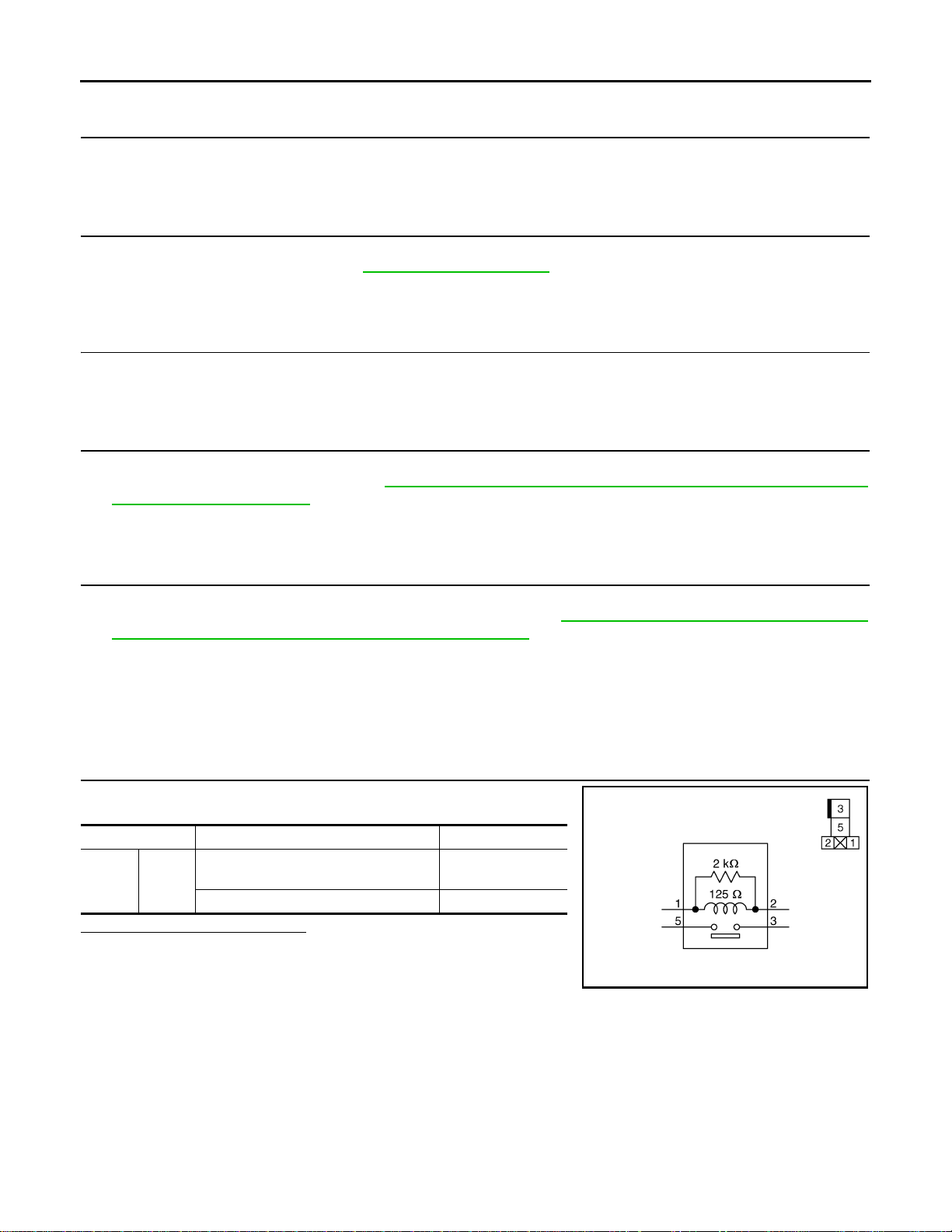
C1A13 STOP LAMP RELAY
B
Revision: 2007 June G37 Coupe
< COMPONENT DIAGNOSIS >
[INTELLIGENT CRUISE CONTROL]
38.REP AIR OR REPLACE HARNESS BETWEEN STOP LAMP SWITCH AND ABS ACTUA TOR AND ELEC-
TRIC UNIT (CONTROL UNIT)
Repair or replace harness between stop lamp switch and ABS actuator and electric unit (control unit).
>> GO TO 42.
39.PERFORM SELF-DIAGNOSIS OF ABS ACTUATOR AND ELECTRIC UNIT (CONTROL UNIT)
1. Perform self-diagnosis of ABS actuator and electric unit (control unit).
2. Check if DTC is detected. Refer to BRC-88, "
>> GO TO 40.
DTC No. Index".
40.REPAIR OR REPLACE APPLICABLE ITEM
Repair or replace the applicable item identified by the self-diagnosis result.
>> GO TO 42.
41.REPLACE ICC SENSOR UNTEGRATED UNIT
1. Replace ICC sensor integrated unit.
2. Adjust laser beam aiming. Refer to CCS-7, "
Requirement (Preparation)".
LASER BEAM AIMING ADJUSTMENT : Special Repair
>> GO TO 42.
42.CHECK ICC SYSTEM
1. Erase DTC and perform ICC system action test. Then perform self-diagnosis of ICC sensor integrated
unit. (For the details on the ICC system action test, refer to CCS-11, "
Requirement (Vehicle-To-Vehicle Distance Control Mode)").
2. Check that no abnormal condition is present in the ICC system.
>> INSPECTION END
ACTION TEST : Special Repair
Component Inspection INFOID:0000000001606900
1.CHECK ICC BRAKE HOLD RELAY
Check continuity between ICC brake hold relay terminals.
terminals condition Continuity
Applying battery voltage to between ter-
35
Is the inspection result normal?
YES >> INSPECTION END
NO >> Replace ICC brake hold relay.
minals 1 and 2
No battery voltage Not existed
Existed
JSOIA0075G
CCS-54
Page 55

< COMPONENT DIAGNOSIS >
Revision: 2007 June G37 Coupe
C1A14 ECM
[INTELLIGENT CRUISE CONTROL]
C1A14 ECM
Description INFOID:0000000001606901
• ECM transmits the accelerator pedal position signal, ICC brake switch signal, stop lamp switch signal and
ICC steering switch signal, etc. to the ICC sensor integrated unit with CAN communication.
• ECM controls the electronic control throttle based on the engine torque demand received from the ICC sensor integrated unit with CAN communication.
NOTE:
If DTC C1A14 is detected along with DTC U1000, first diagnose the DTC U1000. Refer to CCS-79,
"Diagnosis Procedure".
DTC Logic INFOID:0000000001606902
DTC DETECTION LOGIC
DTC No.
(On board
display)
C1A14
(14)
Trouble diagnosis name DTC detecting condition Possible cause
• Accelerator pedal position sensor
ECM CIRCUIT If an abnormal condition occurs with ECM.
•ECM
• ICC sensor integrated unit
Diagnosis Procedure INFOID:0000000001606903
1.PERFORM SELF-DIAGNOSIS OF ICC SENSOR INTEGRA TED UNIT
A
B
C
D
E
F
G
H
1. Perform self-diagnosis of ICC sensor integrated unit.
2. Check if DTC “CAN COMM CIRCUIT [U1000]” (DTC 100) other than “ECM CIRCUIT [C1A14]” (DTC 14)
is detected.
Is any DTC detected?
YES >> GO TO 2.
NO >> GO TO 3.
2.CAN COMMUNICATION INSPECTION
Perform the CAN communication system inspection. Repair or replace the applicable item. Refer to CCS-79,
"Diagnosis Procedure".
>> GO TO 6.
3.PERFORM SELF-DIAGNOSIS OF ECM
1. Perform self-diagnosis of ECM.
2. Check if DTC is detected. Refer to EC-552, "
Is any DTC detected?
YES >> GO TO 4.
NO >> GO TO 5.
DTC Index".
4.REPAIR OR REPLACE APPLICABLE ITEM
Repair or replace the applicable item identified by the self-diagnosis result.
>> GO TO 6.
5.REPLACE ICC SENSOR INTEGRATED UNIT
I
J
K
L
M
N
CCS
P
1. Replace ICC sensor integrated unit
2. Adjust laser beam aiming. Refer to CCS-7, "
Requirement (Preparation)".
>> GO TO 6.
LASER BEAM AIMING ADJUSTMENT : Special Repair
CCS-55
Page 56

C1A14 ECM
Revision: 2007 June G37 Coupe
< COMPONENT DIAGNOSIS >
[INTELLIGENT CRUISE CONTROL]
6.CHECK ICC SYSTEM
1. Erase DTC and perform ICC system action test. Then perform self-diagnosis of ICC sensor integrated
unit. (For the details on the ICC system action test, refer to CCS-11, "
Requirement (Vehicle-To-Vehicle Distance Control Mode)").
2. Check that no abnormal condition is present in the ICC system.
>> INSPECTION END
ACTION TEST : Special Repair
CCS-56
Page 57

< COMPONENT DIAGNOSIS >
Revision: 2007 June G37 Coupe
C1A15 GEAR POSITION
[INTELLIGENT CRUISE CONTROL]
C1A15 GEAR POSITION
Description INFOID:0000000001606904
ICC sensor integrated unit judges gear positions according to the following signals.
• A/T turbine revolution signal transmitted from TCM with CAN communication.
• Gear ratio calculated from current gear position signal transmitted from TCM with CAN communication.
• Gear ratio calculated from vehicle speed signal transmitted from ABS actuator and electronic unit (control
unit) with CAN communication
NOTE:
If DTC C1A15 is detected along with DTC U1000, C1A03 or C1A04, first diagnose the DTC U1000, C1A03 or
C1A04.
• DTC U1000: Refer to CCS-79, "
• DTC C1A03: Refer to CCS-30, "
• DTC C1A04: Refer to CCS-32, "
DTC Logic INFOID:0000000001606905
DTC DETECTION LOGIC
DTC No.
(On board
display)
C1A15
(15)
Trouble diagnosis name DTC detecting condition Possible cause
GEAR POSITION
Diagnosis Procedure INFOID:0000000001606906
Diagnosis Procedure".
Diagnosis Procedure".
Diagnosis Procedure".
When a mismatch occurs between an A/T turbine revolution signal transmitted from TCM
with CAN communication and a vehicle speed
signal transmitted from ABS actuator and electric unit (control unit)
• A/T turbine revolution sensor
•TCM
• Wheel sensor
• ABS actuator and electric unit (control
unit)
A
B
C
D
E
F
G
H
I
1.PERFORM SELF-DIAGNOSIS OF ICC SENSOR INTEGRA TED UNIT
1. Perform self-diagnosis of ICC sensor integrated unit.
2. Check if DTC “VHCL SPEED SE CIRC [C1A03]” (DTC 3), “ABS/TCS/VDC CIRC [C1A04]” (DTC 4) or
“CAN COMM CIRCUIT [U1000]” (DTC100) other than “GEAR POSITION [C1A15]” (DTC 15) is detected.
Is any DTC detected?
YES >> GO TO 2.
NO >> GO TO 3.
2.DIAGNOSIS FOR DETECTED DTC
Perform diagnosis on the detected DTC and repair or replace the applicable item. Refer to CCS-92, "
Index".
>> GO TO 9.
DTC
3.CHECK VEHICLE SPEED SIGNAL
With CONSULT-III
1. Start engine.
2. With “Data Monitor” of “ICC”, check if “VHCL SPEED SE” operates normally.
Is the inspection result normal?
YES >> GO TO 4.
NO >> GO TO 8.
4.CHECK SHIFT GEAR POSITION
Check if gear positions are correct in A/T.
Is the inspection result normal?
YES >> GO TO 6.
NO >> GO TO 5.
J
K
L
M
N
CCS
P
CCS-57
Page 58

C1A15 GEAR POSITION
Revision: 2007 June G37 Coupe
< COMPONENT DIAGNOSIS >
[INTELLIGENT CRUISE CONTROL]
5.CHECK TCM GEAR POSITION SIGNAL
With CONSULT-III
With “Data Monitor” of “A/T”, check if “GEAR” operates normally.
Is the inspection result normal?
YES >> GO TO 8.
NO >> GO TO 7.
6.CHECK TCM TURBINE REVOLUTION
With CONSULT-III
With “Data Monitor” of “A/T”, check if “TURBINE REV” operates normally.
Is the inspection result normal?
YES >> GO TO 8.
NO >> GO TO 7.
7.PERFROM SELF-DIAGNOSIS OF TCM
1. Perform self-diagnosis of TCM.
2. Check if DTC is detected. Refer to TM-186, "
3. Repair or replace applicable item.
>> GO TO 9.
DTC Index".
8.REPLACE ICC SENSOR INTEGARTED UNIT
1. Replace ICC sensor integrated unit.
2. Adjust laser beam aiming. Refer to CCS-7, "
Requirement (Preparation)".
>> GO TO 9.
LASER BEAM AIMING ADJUSTMENT : Special Repair
9.CHECK ICC SYSTEM
1. Erase DTC and perform ICC system action test. Then perform self-diagnosis of ICC sensor integrated
unit. (For the details on the ICC system action test, refer to CCS-11, "
Requirement (Vehicle-To-Vehicle Distance Control Mode)").
2. Check that no abnormal condition is present in the ICC system.
>> INSPECTION END
ACTION TEST : Special Repair
CCS-58
Page 59

< COMPONENT DIAGNOSIS >
Revision: 2007 June G37 Coupe
C1A16 RADAR STAIN
[INTELLIGENT CRUISE CONTROL]
C1A16 RADAR STAIN
Description INFOID:0000000001606907
ICC sensor integrated unit irradiates laser beam, and receives reflected laser beam to measure distance from
preceding vehicle.
DTC Logic INFOID:0000000001606908
DTC DETECTION LOGIC
DTC No.
(On board
display)
C1A16
(16)
Trouble diagnosis
name
RADAR STAIN
DTC detecting condition Possible cause
If any stain occurs to ICC sensor integrated unit
body window.
Stai n or foreign materials is deposited
Diagnosis Procedure INFOID:0000000001606909
1.VISUAL INSPECTION 1
Check ICC sensor integrated unit body window for contamination and foreign materials.
Is it found?
YES >> GO TO 2.
NO >> GO TO 3.
2.REMOVE DIRT AND FOREIGN OBJECTS
A
B
C
D
E
F
G
H
Remove any stain and foreign materials from the ICC sensor integrated unit body window.
>> GO TO 6.
3.VISUAL INSPECTION 2
Check ICC sensor integrated unit body window for cracks and scratches.
Is it found?
YES >> GO TO 5.
NO >> GO TO 4.
4.ASKING COMPLAINTS
1. Ask if there is any trace of contamination or foreign material on ICC sensor integrated unit.
2. Ask if vehicle was driven in snow or ICC sensor integrated unit was frosted.
3. Ask if ICC sensor integrated unit was fogged temporarily. (Front window glass may have also tended to be
fogged.)
Is there any symptom?
YES >> Explain difference in displays between contamination detection result and current indication to
customer, and tell them “This is not malfunction”.
NO >> GO TO 5.
5.REPLACE ICC SENSOR INTEGRATED UNIT
1. Replace ICC sensor integrated unit.
2. Adjust laser beam aiming. Refer to CCS-7, "
Requirement (Preparation)".
LASER BEAM AIMING ADJUSTMENT : Special Repair
I
J
K
L
M
N
CCS
P
>> GO TO 6.
6.CHECK ICC SYSTEM
1. Erase DTC and perform ICC system action test. Then perform self-diagnosis of ICC sensor integrated
unit. (For the details on the ICC system action test, refer to CCS-11, "
Requirement (Vehicle-To-Vehicle Distance Control Mode)").
CCS-59
ACTION TEST : Special Repair
Page 60

C1A16 RADAR STAIN
Revision: 2007 June G37 Coupe
< COMPONENT DIAGNOSIS >
2. Check that no abnormal condition is present in the ICC system.
>> INSPECTION END
[INTELLIGENT CRUISE CONTROL]
CCS-60
Page 61

< COMPONENT DIAGNOSIS >
Revision: 2007 June G37 Coupe
C1A18 LASER AIMING INCMP
[INTELLIGENT CRUISE CONTROL]
C1A18 LASER AIMING INCMP
Description INFOID:0000000001606910
Always perform laser beam aiming adjustment after replacing ICC sensor integrated unit.
DTC Logic INFOID:0000000001606911
DTC DETECTION LOGIC
DTC No.
(On board
display)
C1A18
(18)
Trouble diagnosis
name
LASER AIMING INC-MPLaser beam aiming of ICC sensor int egrated un it
is not adjusted.
DTC detecting condition Possible cause
• No laser beam aiming adjustment is performed
• Laser beam aiming adjustment has been
interrupted
Diagnosis Procedure INFOID:0000000001606912
1.ADJUST LASER BEAM AIMING
1. Adjust laser beam aiming. Refer to CCS-6, "
2. Erase DTC.
3. Activate the vehicle-to-vehicle distance control mode.
4. Perform self-diagnosis of ICC sensor integrated unit.
5. Check if DTC “LASER AIMING INCMP [C1A18]” (DTC 18) is detected.
Is any DTC detected?
YES >> GO TO 2.
NO >> INSPECTION END
LASER BEAM AIMING ADJUSTMENT : Description".
2.REPLACE ICC SENSOR INTEGRATED UNIT
1. Replace ICC sensor integrated unit.
2. Adjust laser beam aiming. Refer to CCS-7, "
Requirement (Preparation)".
LASER BEAM AIMING ADJUSTMENT : Special Repair
A
B
C
D
E
F
G
H
I
J
K
>> GO TO 3.
3.CHECK ICC SYSTEM
1. Erase DTC and perform ICC system action test. Then perform self-diagnosis of ICC sensor integrated
unit. (For the details on the ICC system action test, refer to CCS-11, "
Requirement (Vehicle-To-Vehicle Distance Control Mode)").
2. Check that no abnormal condition is present in the ICC system.
>> INSPECTION END
CCS-61
ACTION TEST : Special Repair
L
M
N
CCS
P
Page 62

C1A21 UNIT HIGH TEMP
Revision: 2007 June G37 Coupe
< COMPONENT DIAGNOSIS >
[INTELLIGENT CRUISE CONTROL]
C1A21 UNIT HIGH TEMP
Description INFOID:0000000001606913
ICC sensor integrated unit integrates a temperature sensor.
DTC Logic INFOID:0000000001606914
DTC DETECTION LOGIC
DTC No.
(On board
display)
C1A21
(21)
Trouble diagnosis
name
UNIT HIGH TEMP
DTC detecting condition Possible cause
If temperature sensor (built in ICC sensor integrated unit) detects a high temperature.
T emp erature around ICC sens or integrated
unit is excessively high
Diagnosis Procedure INFOID:0000000001606915
1.CHECK SYMPTOM
Check if engine cooling system malfunctions.
Does it malfunction?
YES >> GO TO 2.
NO >> GO TO 3.
2.REPAIR ENGINE COOLING SYSTEM
Repair engine cooling system.
>> GO TO 4.
3.REPLACE ICC SENSOR INTEGRATED UNIT
1. Replace ICC sensor integrated unit.
2. Adjust laser beam aiming. Refer to CCS-7, "
Requirement (Preparation)".
LASER BEAM AIMING ADJUSTMENT : Special Repair
>> GO TO 4.
4.CHECK ICC SYSTEM
1. Erase DTC and perform ICC system action test. Then perform self-diagnosis of ICC sensor integrated
unit. (For the details on the ICC system action test, refer to CCS-11, "
Requirement (Vehicle-To-Vehicle Distance Control Mode)").
2. Check that no abnormal condition is present in the ICC system.
>> INSPECTION END
CCS-62
ACTION TEST : Special Repair
Page 63

< COMPONENT DIAGNOSIS >
Revision: 2007 June G37 Coupe
C1A24 NP RANGE
[INTELLIGENT CRUISE CONTROL]
C1A24 NP RANGE
Description INFOID:0000000001606916
Park/neutral position switch signal is transmitted by TCM to ICC sensor integrated unit with CAN communication (A/T).
NOTE:
If DTC C1A24 is detected along with DTC U1000 or U0402, first diagnose the DTC U1000 or U0402.
• DTC U1000: Refer to CCS-79, "
• DTC U0402: Refer to CCS-75, "
Diagnosis Procedure".
Diagnosis Procedure".
DTC Logic INFOID:0000000001606917
DTC DETECTION LOGIC
DTC No.
(On board
display)
C1A24
(24)
Trouble diagnosis name DTC detecting condition Possible cause
• Park/neutral position switch signal
• Current gear position signal
•TCM
NP RANGE
If park/neutral position sw itch signal and current
gear position signal, transmitted by TCM with
CAN communication, are inconsistent.
Diagnosis Procedure INFOID:0000000001606918
1.PERFORM SELF-DIAGNOSIS OF ICC SENSOR INTEGRA TED UNIT
1. Perform self-diagnosis of ICC sensor integrated unit.
2. Check if DTC “CAN COMM CIRCUIT [U1000]” (DTC100) or “TCM CAN CIR 1 [U0402]” (DTC 122) other
than “NP RANGE [C1A24]” (DTC 24) is detected.
Is any DTC detected?
YES >> GO TO 2.
NO >> GO TO 3.
2.DIAGNOSIS FOR DETECTED DTC
A
B
C
D
E
F
G
H
I
J
Perform diagnosis on the detected and repair or replace the applicable item. Refer to CCS-92, "
>> GO TO 6.
3.CHECK DATA MONITOR OF TCM
With CONSULT-III
With “Data Monitor” of “A/T”, check if “SLCT LVR POSI” are operates normally.
Is the inspection result normal?
YES >> GO TO 5.
NO >> GO TO 4.
4.PERFORM SELF-DIAGNOSIS OF TCM
1. Perform self-diagnosis of TCM.
2. Replace or replace applicable item. Refer o TM-186, "
>> GO TO 6.
DTC Index".
5.REPLACE ICC SENSOR INTEGRATED UNIT
1. Replace ICC sensor integrated unit.
2. Adjust laser beam aiming. Refer to CCS-7, "
Requirement (Preparation)".
>> GO TO 6.
LASER BEAM AIMING ADJUSTMENT : Special Repair
DTC Index".
K
L
M
N
CCS
P
CCS-63
Page 64

C1A24 NP RANGE
Revision: 2007 June G37 Coupe
< COMPONENT DIAGNOSIS >
[INTELLIGENT CRUISE CONTROL]
6.CHECK ICC SYSTEM
1. Erase DTC and perform ICC system action test. Then perform self-diagnosis of ICC sensor integrated
unit. (For the details on the ICC system action test, refer to CCS-11, "
Requirement (Vehicle-To-Vehicle Distance Control Mode)").
2. Check that no abnormal condition is present in the ICC system.
>> INSPECTION END
ACTION TEST : Special Repair
CCS-64
Page 65

C1A26 ECD MODE MALFUNCTION
Revision: 2007 June G37 Coupe
< COMPONENT DIAGNOSIS >
[INTELLIGENT CRUISE CONTROL]
C1A26 ECD MODE MALFUNCTION
Description INFOID:0000000001606919
ECD (ELECTRONICALLY CONTROLLED DECELERATION)
• Receives deceleration degree commandment value signal from ICC sensor integrated unit, and controls
brake fluid pressure with the motor [built in ABS actuator and electric unit (control unit)].
• ECD control-related signals are transmitted by ABS actuator and electric unit (control unit) to ICC sensor
integrated unit with CAN communication.
NOTE:
If DTC C1A26 is detected along with DTC U1000, U0415 or U0121 first diagnose the DTC U1000, U0415 or
U0121.
• DTC U1000: Refer to CCS-79, "
• DTC U0415: Refer to CCS-77, "
• DTC U0121: Refer to CCS-71, "
DTC Logic INFOID:0000000001606920
DTC DETECTION LOGIC
DTC No.
(On board
display)
C1A26
(26)
Trouble diagnosis name DTC detecting condition Possible cause
ECD MODE MALF If an abnormal condition occurs with ECD system.
Diagnosis Procedure".
Diagnosis Procedure".
Diagnosis Procedure".
ABS actuator and electric unit (control
unit)
A
B
C
D
E
F
G
H
Diagnosis Procedure INFOID:0000000001606921
1.PERFORM SELF-DIAGNOSIS OF ICC SENSOR INTEGRA TED UNIT
1. Perform self-diagnosis of ICC sensor integrated unit.
2. Check if DTC “CAN COMM CIRCUIT [U1000]” (DTC 100) or “VDC CAN CIR 1 [U0415]” (DTC 126), “VDC
CAN CIR 2 [U0121]” (DTC 127) other than “ECD MODE MALF [C1A26]” (DTC 26) is detected.
Is any DTC detected?
YES >> GO TO 2.
NO >> GO TO 3.
2.DIAGNOSIS FOR DETECTED DTC
Perform diagnosis on the detected DTC and repair or replace the applicable item. Refer to CCS-92, "
Index".
>> GO TO 6.
DTC
3.PERFORM SELF-DIAGNOSIS OF ABS ACTUATOR AND ELECTRIC UNIT (CONTROL UNIT)
1. Perform self-diagnosis of ABS actuator and electric unit (control unit).
2. Check if DTC is detected. Refer to BRC-88, "
Is any DTC detected?
YES >> GO TO 4.
NO >> GO TO 5.
DTC No. Index".
4.REPAIR OR REPLACE APPLICABLE ITEM
Repair or replace the applicable item identified by the self-diagnosis result.
I
J
K
L
M
N
CCS
P
>> GO TO 6.
5.REPLACE ICC SESNOR INTEGRATED UNIT
1. Replace ICC sensor integrated unit.
CCS-65
Page 66

C1A26 ECD MODE MALFUNCTION
Revision: 2007 June G37 Coupe
< COMPONENT DIAGNOSIS >
2. Adjust laser beam aiming. Refer to CCS-7, "LASER BEAM AIMING ADJUSTMENT : Special Repair
Requirement (Preparation)".
>> GO TO 6.
[INTELLIGENT CRUISE CONTROL]
6.CHECK ICC SYSTEM
1. Erase DTC and perform ICC system action test. Then perform self-diagnosis of ICC sensor integrated
unit. (For the details on the ICC system action test, refer to CCS-11, "
Requirement (Vehicle-To-Vehicle Distance Control Mode)").
2. Check that no abnormal condition is present in the ICC system.
>> INSPECTION END
ACTION TEST : Special Repair
CCS-66
Page 67

C1A27 ECD POWER SUPPLY CIRCUIT
Revision: 2007 June G37 Coupe
< COMPONENT DIAGNOSIS >
[INTELLIGENT CRUISE CONTROL]
C1A27 ECD POWER SUPPLY CIRCUIT
Description INFOID:0000000001606922
ECD (ELECTRONICALLY CONTROLLED DECELERATION)
• Receives deceleration degree commandment value signal from ICC sensor integrated unit, and controls
brake fluid pressure with the motor [built in ABS actuator and electric unit (control unit)].
• ECD control-related signals are transmitted by ABS actuator and electric unit (control unit) to ICC sensor
integrated unit with CAN communication.
NOTE:
If DTC C1A27 is detected along with DTC U1000, U0415 or U0121 first diagnose the DTC U1000, U0415 or
U0121.
• DTC U1000: Refer to CCS-79, "
• DTC U0415: Refer to CCS-77, "
• DTC U0121: Refer to CCS-71, "
DTC Logic INFOID:0000000001606923
DTC DETECTION LOGIC
DTC No.
(On board
display)
C1A27
(27)
Trouble diagnosis name DTC detecting condition Possible cause
ECD PWR SUPLY CIR
Diagnosis Procedure INFOID:0000000001606924
Diagnosis Procedure".
Diagnosis Procedure".
Diagnosis Procedure".
ECD system power supply voltage is exces sively
low.
• ABS actuator and electric unit (control unit) power supply circuit
• ABS actuator and electric unit (control unit)
A
B
C
D
E
F
G
H
I
1.PERFORM SELF-DIAGNOSIS OF ICC SENSOR INTEGRA TED UNIT
1. Perform self-diagnosis of ICC sensor integrated unit.
2. Check if DTC “CAN COMM CIRCUIT [U1000]” (DTC 100) or “VDC CAN CIR 1 [U0415]” (DTC 126), “VDC
CAN CIR 2 [U0121]” (DTC 127) other than “ECD PWR SUPLY CIR [C1A27]” (DTC 27) is detected.
Is any DTC detected?
YES >> GO TO 2.
NO >> GO TO 3.
2.DIAGNOSIS FOR DETECTED DTC
Perform diagnosis on the detected DTC and repair or replace the applicable item. Refer to CCS-92, "
Index".
>> GO TO 6.
DTC
3.CHECK POWER SUPPLY CIRCUIT OF ABS ACTUATOR AND ELECTRIC UNIT (CONTROL UNIT)
Check power supply circuit of ABS actuator and electric unit (control unit). Refer to BRC-37, "
dure".
Is the inspection result normal?
YES >> GO TO 5.
NO >> GO TO 4.
Diagnosis Proce-
4.REPAIR OR REPLACE ABS ACTUATOR AND ELECTRIC UNIT (CONTROL UNIT) POWER SUPPLY
Repair or replace ABS actuator and electric unit (control unit) power supply.
J
K
L
M
N
CCS
P
>> GO TO 6.
5.PERFORM SELF-DIAGNOSIS OF ABS ACTUATOR AND ELECTRIC UNIT (CONTROL UNIT)
CCS-67
Page 68

C1A27 ECD POWER SUPPLY CIRCUIT
Revision: 2007 June G37 Coupe
< COMPONENT DIAGNOSIS >
1. Perform self-diagnosis of ABS actuator and electric unit (control unit).
2. Repair or replace applicable item. Refer to BRC-88, "
>> GO TO 6.
DTC No. Index".
[INTELLIGENT CRUISE CONTROL]
6.CHECK ICC SYSTEM
1. Erase DTC and perform ICC system action test. Then perform self-diagnosis of ICC sensor integrated
unit. (For the details on the ICC system action test, refer to CCS-11, "
Requirement (Vehicle-To-Vehicle Distance Control Mode)").
2. Check that no abnormal condition is present in the ICC system.
>> INSPECTION END
ACTION TEST : Special Repair
CCS-68
Page 69

C1A33 CAN TRANSMISSION ERROR
Revision: 2007 June G37 Coupe
< COMPONENT DIAGNOSIS >
[INTELLIGENT CRUISE CONTROL]
C1A33 CAN TRANSMISSION ERROR
Description INFOID:0000000001685791
ICC sensor integrated unit transmits a signal required by ICC system to ECM with CAN communication.
NOTE:
If DTC C1A33 is detected along with DTC U1000, first diagnose the DTC U1000. Refer to CCS-79,
"Diagnosis Procedure".
DTC Logic INFOID:0000000001685792
DTC DETECTION LOGIC
DTC No.
(On board
display)
C1A33
(33)
Trouble diagnosis name DTC detecting condition Possible cause
CAN TRANSMISSIN ERROR
If an error occurs in CAN communication signal
that ICC sensor integrated unit t ransmits to ECM
ICC sensor integrated unit
Diagnosis Procedure INFOID:0000000001685793
1.PERFORM SELF-DIAGNOSIS OF ICC SENSOR INTEGRA TED UNIT
1. Perform self-diagnosis of ICC sensor integrated unit.
2. Check if DTC “CAN COMM CIRCUIT [U1000]” (DTC 100) other than “CAN TRANSMISSION ERROR
[C1A33]” (DTC 33) is detected.
Is any DTC detected?
YES >> GO TO 2.
NO >> GO TO 3.
2.CAN COMMUNICATION INSPECTION
A
B
C
D
E
F
G
H
I
Perform the CAN communication system inspection. Repair or replace the applicable item. Refer to CCS-79,
"Diagnosis Procedure".
>> GO TO 4.
3.REPLACE ICC SENSOR INTEGRATED UNIT
1. Replace ICC sensor integrated unit.
2. Adjust laser beam aiming. Refer to CCS-7, "
Requirement (Preparation)".
>> GO TO 4.
LASER BEAM AIMING ADJUSTMENT : Special Repair
4.CHECK ICC SYSTEM
1. Erase DTC and perform ICC system action test. Then perform self-diagnosis of ICC sensor integrated
unit. (For the details on the ICC system action test, refer to CCS-11, "
Requirement (Vehicle-To-Vehicle Distance Control Mode)").
2. Check that no abnormal condition is present in the ICC system.
>> INSPECTION END
ACTION TEST : Special Repair
J
K
L
M
N
CCS
P
CCS-69
Page 70

C1A34 COMMAND ERROR
Revision: 2007 June G37 Coupe
< COMPONENT DIAGNOSIS >
[INTELLIGENT CRUISE CONTROL]
C1A34 COMMAND ERROR
Description INFOID:0000000001685794
ICC sensor integrated unit sends command signal required for ECM control with CAN communication.
NOTE:
If DTC C1A34 is detected along with DTC U1000, first diagnose the DTC U1000. Refer to CCS-79,
"Diagnosis Procedure".
DTC Logic INFOID:0000000001685795
DTC DETECTION LOGIC
DTC No.
(On board
display)
C1A34
(34)
Diagnosis Procedure INFOID:0000000001685796
Trouble diagnosis name DTC detecting condition Possible cause
If an error occurs in the command signal tha t ICC
COMMAND ERROR
sensor integrated unit transmits to ECM with CAN
communication
ICC sensor integrated unit
1.PERFORM SELF-DIAGNOSIS OF ICC SENSOR INTEGRATED UNIT
1. Perform self-diagnosis of ICC sensor integrated unit.
2. Check if DTC “CAN COMM CIRCUIT [U1000]” (DTC 100) other than “COMMAND ERROR [C1A34]”
(DTC 34) is detected.
Is any DTC detected?
YES >> GO TO 2.
NO >> GO TO 3.
2.CAN COMMUNICATION INSPECTION
Perform the CAN communication system inspection. Repair or replace the applicable item. Refer to CCS-79,
"Diagnosis Procedure".
>> GO TO 4.
3.REPLACE ICC SENSOR INTEGRATED UNIT
1. Replace ICC sensor integrated unit.
2. Adjust laser beam aiming. Refer to CCS-7, "
Requirement (Preparation)".
>> GO TO 4.
LASER BEAM AIMING ADJUSTMENT : Special Repair
4.CHECK ICC SYSTEM
1. Erase DTC and perform ICC system action test. Then perform self-diagnosis of ICC sensor integrated
unit. (For the details on the ICC system action test, refer to CCS-11, "
Requirement (Vehicle-To-Vehicle Distance Control Mode)").
2. Check that no abnormal condition is present in the ICC system.
ACTION TEST : Special Repair
>> INSPECTION END
CCS-70
Page 71

< COMPONENT DIAGNOSIS >
Revision: 2007 June G37 Coupe
U0121 VDC CAN 2
[INTELLIGENT CRUISE CONTROL]
U0121 VDC CAN 2
Description INFOID:0000000001606925
ABS actuator and electric unit (control unit) transmits VDC system signal to ICC sensor integrated unit with
CAN communication.
NOTE:
If DTC U0121 is detected along with DTC U1000, first diagnose the DTC U1000. Refer to CCS-79,
"Diagnosis Procedure".
DTC Logic INFOID:0000000001606926
DTC DETECTION LOGIC
DTC No.
(On board
display)
U0121
(127)
Trouble diagnosis name DTC detecting condition Possible cause
When a mismatch occurs between a VDC system
VDC CAN CIR2
signal transmitted from ABS actuator electric unit
(control unit) and a VDC system signal received by
ICC sensor integrated unit.
ABS actuator and electric unit (control
unit)
Diagnosis Procedure INFOID:0000000001606927
1.PERFORM SELF-DIAGNOSIS OF ICC SENSOR INTEGRA TED UNIT
1. Perform self-diagnosis of ICC sensor integrated unit.
2. Check if DTC “CAN COMM CIRCUIT [U1000]” (DTC 100) other than “VDC CAN CIR2 [U0121]” (DTC
127) is detected.
Is any DTC detected?
YES >> GO TO 2.
NO >> GO TO 3.
2.CAN COMMUNICATION INSPECTION
A
B
C
D
E
F
G
H
I
J
Perform the CAN communication system inspection. Repair or replace the applicable item. Refer to CCS-79,
"Diagnosis Procedure".
>> GO TO 6.
3.PERFORM SELF-DIAGNOSIS OF ABS ACTUATOR AND ELECTRIC UNIT (CONTROL UNIT)
1. Perform self-diagnosis of ABS actuator and electric unit (control unit).
2. Check if DTC is detected. Refer to BRC-88, "
Is any DTC detected?
YES >> GO TO 4.
NO >> GO TO 5.
DTC No. Index".
4.REPAIR OR REPLACE APPLICABLE ITEM
Repair or replace the applicable item identified by the self-diagnosis result.
>> GO TO 6.
5.REPLACE ICC SENSOR INTEGRATED UNIT
1. Replace ICC sensor integrated unit.
2. Adjust laser beam aiming. Refer to CCS-7, "
Requirement (Preparation)".
>> GO TO 6.
LASER BEAM AIMING ADJUSTMENT : Special Repair
6.CHECK ICC SYSTEM
K
L
M
N
CCS
P
CCS-71
Page 72

U0121 VDC CAN 2
Revision: 2007 June G37 Coupe
< COMPONENT DIAGNOSIS >
1. Erase DTC and perform ICC system action test. Then perform self-diagnosis of ICC sensor integrated
unit. (For the details on the ICC system action test, refer to CCS-11, "
Requirement (Vehicle-To-Vehicle Distance Control Mode)").
2. Check that no abnormal condition is present in the ICC system.
>> INSPECTION END
[INTELLIGENT CRUISE CONTROL]
ACTION TEST : Special Repair
CCS-72
Page 73

< COMPONENT DIAGNOSIS >
Revision: 2007 June G37 Coupe
U0401 ECM CAN 1
[INTELLIGENT CRUISE CONTROL]
U0401 ECM CAN 1
Description INFOID:0000000001606928
ICC sensor integrated unit and ECM exchange ECM system-related signals with CAN communication.
NOTE:
If DTC U0401 is detected along with DTC U1000, first diagnose the DTC U1000. Refer to CCS-79,
"Diagnosis Procedure".
DTC Logic INFOID:0000000001606929
DTC DETECTION LOGIC
DTC No.
(On board
display)
U0401
(120)
Trouble diagnosis name DTC detecting condition Possible cause
ECM CAN CIR1
When a counter value of CAN signals received
from ECM does not change.
ECM
Diagnosis Procedure INFOID:0000000001606930
1.PERFORM SELF-DIAGNOSIS OF ICC SENSOR INTEGRA TED UNIT
1. Perform self-diagnosis of ICC sensor integrated unit.
2. Check if DTC “CAN COMM CIRCUIT [U1000]” (DTC 100) other than “ECM CAN CIR1 [U0401]” (DTC
120) is detected.
Is any DTC detected?
YES >> GO TO 2.
NO >> GO TO 3.
2.CAN COMMUNICATION INSPECTION
A
B
C
D
E
F
G
H
I
Perform the CAN communication system inspection. Repair or replace the applicable item. Refer to CCS-79,
"Diagnosis Procedure".
>> GO TO 6.
3.PERFORM SELF-DIAGNOSIS OF ECM
1. Perform self-diagnosis of ECM.
2. Check if DTC is detected. Refer to EC-552, "
Is any DTC detected?
YES >> GO TO 4.
NO >> GO TO 5.
DTC Index".
4.REPAIR OR REPLACE APPLICABLE ITEM
Repair or replace the applicable item identified by the self-diagnosis result.
>> GO TO 6.
5.REPLACE ICC SENSOR INTEGRATED UNIT
1. Replace ICC sensor integrated unit.
2. Adjust laser beam aiming. Refer to CCS-7, "
Requirement (Preparation)".
>> GO TO 6.
LASER BEAM AIMING ADJUSTMENT : Special Repair
6.CHECK ICC SYSTEM
J
K
L
M
N
CCS
P
CCS-73
Page 74

U0401 ECM CAN 1
Revision: 2007 June G37 Coupe
< COMPONENT DIAGNOSIS >
1. Erase DTC and perform ICC system action test. Then perform self-diagnosis of ICC sensor integrated
unit. (For the details on the ICC system action test, refer to CCS-11, "
Requirement (Vehicle-To-Vehicle Distance Control Mode)").
2. Check that no abnormal condition is present in the ICC system.
>> INSPECTION END
[INTELLIGENT CRUISE CONTROL]
ACTION TEST : Special Repair
CCS-74
Page 75

< COMPONENT DIAGNOSIS >
Revision: 2007 June G37 Coupe
U0402 TCM CAN 1
[INTELLIGENT CRUISE CONTROL]
U0402 TCM CAN 1
Description INFOID:0000000001606931
TCM transmits A/T control system signal to ICC sensor integrated unit with CAN communication.
NOTE:
If DTC U402 is detected along with DTC U1000, first diagnose the DTC U1000. Refer to CCS-79,
"Diagnosis Procedure".
DTC Logic INFOID:0000000001606932
DTC DETECTION LOGIC
DTC No.
(On board
display)
U0402
(122)
Trouble diagnosis name DTC detecting condition Possible cause
TCM CAN CIR1
When a counter value of CAN signals received
from TCM does not change.
TCM
Diagnosis Procedure INFOID:0000000001606933
1.PERFORM SELF-DIAGNOSIS OF ICC SENSOR INTEGRA TED UNIT
1. Perform self-diagnosis of ICC sensor integrated unit.
2. Check if DTC “CAN COMM CIRCUIT [U1000]” (DTC 100) other than “TCM CAN CIR1 [U0402]” (DTC
122) is detected.
Is any DTC detected?
YES >> GO TO 2.
NO >> GO TO 3.
2.CAN COMMUNICATION INSPECTION
A
B
C
D
E
F
G
H
I
Perform the CAN communication system ′inspection. Repair or replace the applicable item. Refer to CCS-79,
"Diagnosis Procedure".
>> GO TO 6.
3.PERFORM SELF-DIAGNOSIS OF TCM
1. Perform self-diagnosis of TCM.
2. Check if DTC is detected. Refer to TM-186, "
Is any DTC detected?
YES >> GO TO 4.
NO >> GO TO 5.
DTC Index".
4.REPAIR OR REPLACE APPLICABLE ITEM
Repair or replace the applicable item identified by the self-diagnosis result.
>> GO TO 6.
5.REPLACE ICC SENSOR INTEGRATED UNIT
1. Replace ICC sensor integrated unit.
2. Adjust laser beam aiming. Refer to CCS-7, "
Requirement (Preparation)".
>> GO TO 6.
LASER BEAM AIMING ADJUSTMENT : Special Repair
6.CHECK ICC SYSTEM
J
K
L
M
N
CCS
P
CCS-75
Page 76

U0402 TCM CAN 1
Revision: 2007 June G37 Coupe
< COMPONENT DIAGNOSIS >
1. Erase DTC and perform ICC system action test. Then perform self-diagnosis of ICC sensor integrated
unit. (For the details on the ICC system action test, refer to CCS-11, "
Requirement (Vehicle-To-Vehicle Distance Control Mode)").
2. Check that no abnormal condition is present in the ICC system.
>> INSPECTION END
[INTELLIGENT CRUISE CONTROL]
ACTION TEST : Special Repair
CCS-76
Page 77

< COMPONENT DIAGNOSIS >
Revision: 2007 June G37 Coupe
U0415 VDC CAN 1
[INTELLIGENT CRUISE CONTROL]
U0415 VDC CAN 1
Description INFOID:0000000001606934
ABS actuator and electric unit (control unit) transmits VDC system signal to ICC sensor integrated unit with
CAN communication.
NOTE:
If DTC U0415 is detected along with DTC U1000 or U0121, first diagnose the DTC U1000 or U0121.
• DTC U1000: Refer to CCS-79, "
• DTC U0121: Refer to CCS-71, "
Diagnosis Procedure".
Diagnosis Procedure".
DTC Logic INFOID:0000000001606935
DTC DETECTION LOGIC
DTC No.
(On board
display)
U0415
(126)
Trouble diagnosis name DTC detecting condition Possible cause
VDC CAN CIR1
When a counter value of CAN signals received
from ABS actuator and electric unit (control unit)
does not change.
ABS actuator and electric unit (control
unit)
Diagnosis Procedure INFOID:0000000001606936
1.PERFORM SELF-DIAGNOSIS OF ICC SENSOR INTEGRA TED UNIT
1. Perform self-diagnosis of ICC sensor integrated unit.
2. Check if DTC “CAN COMM CIRCUIT [U1000]” (DTC 100) or “VDC CAN CIR 1 [U0121]” (DTC 127) other
than “VDC CAN CIR2 [U0415]” (DTC 126) is detected.
Is any DTC detected?
YES >> GO TO 2.
NO >> GO TO 3.
2.DIAGNOSIS FOR DETECTED DTC
A
B
C
D
E
F
G
H
I
J
Perform diagnosis on the detected DTC and repair or replace the applicable item. Refer to CCS-92, "
Index".
>> GO TO 6.
3.PERFORM SELF-DIAGNOSIS OF ABS ACTUATOR AND ELECTRIC UNIT (CONTROL UNIT)
1. Perform self-diagnosis of ABS actuator and electric unit (control unit).
2. Check if DTC is detected. Refer to BRC-88, "
Is any DTC detected?
YES >> GO TO 4.
NO >> GO TO 5.
DTC No. Index".
4.REPAIR OR REPLACE APPLICABLE ITEM
Repair or replace the applicable item identified by the self-diagnosis result.
>> GO TO 6.
5.REPLACE ICC SENSOR INTEGRATED UNIT
1. Replace ICC sensor integrated unit.
2. Adjust laser beam aiming. Refer to CCS-7, "
Requirement (Preparation)".
>> GO TO 6.
LASER BEAM AIMING ADJUSTMENT : Special Repair
6.CHECK ICC SYSTEM
DTC
K
L
M
N
CCS
P
CCS-77
Page 78

U0415 VDC CAN 1
Revision: 2007 June G37 Coupe
< COMPONENT DIAGNOSIS >
1. Erase DTC and perform ICC system action test. Then perform self-diagnosis of ICC sensor integrated
unit. (For the details on the ICC system action test, refer to CCS-11, "
Requirement (Vehicle-To-Vehicle Distance Control Mode)").
2. Check that no abnormal condition is present in the ICC system.
>> INSPECTION END
[INTELLIGENT CRUISE CONTROL]
ACTION TEST : Special Repair
CCS-78
Page 79

< COMPONENT DIAGNOSIS >
Revision: 2007 June G37 Coupe
U1000 CAN COMM CIRCUIT
[INTELLIGENT CRUISE CONTROL]
U1000 CAN COMM CIRCUIT
Description INFOID:0000000001606937
• CAN communication is a multiplex communication system. This enables it to transmit and receive many
communication signals at high speed by connecting control units with two communication lines (CAN-H and
CAN-L).
• Control units on the CAN network transmit signals with CAN communication control circuit in the control unit
and receive only necessary signals from other control units for various controls.
• CAN communication lines adopt twisted-pair line style (two lines twisted) for noise immunity.
DTC Logic INFOID:0000000001606938
DTC DETECTION LOGIC
DTC No.
(On board
display)
U1000
(100)
Trouble diagnosis name DTC detecting condition Possible cause
When ICC sensor integrated unit is not transmit-
CAN COMM CIRCUIT
ting or receiving CAN communication signal for 2
seconds or more.
CAN communication
Diagnosis Procedure INFOID:0000000001606939
1.PERFORM SELF DIAGNOSTIC
1. Turn ignition switch ON and wait for 2 seconds or more.
2. Check “Self Diagnostic Result”.
“CAN COMM CIRCUIT” displayed?
Is
YES >> Go to “LAN system”. Refer to LAN-16, "Trouble Diagnosis Flow Chart".
NO >> Refer to GI-38, "
Intermittent Incident".
A
B
C
D
E
F
G
H
I
J
K
L
M
N
CCS
P
CCS-79
Page 80

U1010 CONTROL UNIT (CAN)
Revision: 2007 June G37 Coupe
< COMPONENT DIAGNOSIS >
[INTELLIGENT CRUISE CONTROL]
U1010 CONTROL UNIT (CAN)
Description INFOID:0000000001606940
Initial diagnosis for ICC sensor integrated unit.
DTC Logic INFOID:0000000001606941
DTC DETECTION LOGIC
DTC No.
(On board
display)
U1010
(110)
Trouble diagnosis name DTC detecting condition Possible cause
CONTROL UNIT (CAN)
ICC sensor integrated unit detects malfunction by
CAN initial diagnosis.
• ICC sensor integrated unit
• CAN communication
Diagnosis Procedure INFOID:0000000001606942
1.PERFORM SELF-DIAGNOSIS OF ICC SENSOR INTEGRATED UNIT
1. Perform self-diagnosis of ICC sensor integrated unit.
2. Print self-diagnosis result.
3. Erase DTC.
4. Perform self-diagnosis of ICC sensor integrated unit again.
5. Check if DTC “CONTROL UNIT (CAN) [U1010]” (DTC110) is detected.
Is any DTC detected?
YES >> GO TO 2.
NO >> INSPECTION END
2.REPLACE ICC SENSOR INTEGRATED UNIT
1. Replace ICC sensor integrated unit.
2. Adjust laser beam aiming. Refer to CCS-7, "
Requirement (Preparation)".
>> GO TO 3.
LASER BEAM AIMING ADJUSTMENT : Special Repair
3.CHECK ICC SYSTEM
1. Erase DTC and perform ICC system action test. Then perform self-diagnosis of ICC sensor integrated
unit. (For the details on the ICC system action test, refer to CCS-11, "
Requirement (Vehicle-To-Vehicle Distance Control Mode)").
2. Check that no abnormal condition is present in the ICC system.
>> INSPECTION END
ACTION TEST : Special Repair
CCS-80
Page 81

POWER SUPPLY AND GROUND CIRCUIT
Revision: 2007 June G37 Coupe
< COMPONENT DIAGNOSIS >
[INTELLIGENT CRUISE CONTROL]
POWER SUPPLY AND GROUND CIRCUIT
Diagnosis Procedure INFOID:0000000001606943
1.CHECK FUSE
Check for blown fuses.
Power source Fuse No.
Ignition switch ON or START 45
Is the inspection result normal?
YES >> GO TO 2.
NO >> Be sure to eliminate cause of malfunction before installing new fuse.
2.CHECK POWER SUPPLY CIRCUIT FOR ICC SENSOR INTEGRATED UNIT
1. Turn ignition switch OFF.
2. Disconnect ICC sensor integrated unit connector.
3. Turn ignition switch ON.
4. Check voltage between ICC sensor integrated unit harness connector and ground.
Terminals
Voltage
(Approx.)
ICC sensor integrated
unit connector
E67 1 Ground Battery voltage
(+)
Terminal
(–)
Is the inspection result normal?
YES >> GO TO 3.
NO >> Repair or replace ICC sensor integrated unit power supply harness or fuse.
3.CHECK GROUND CIRCUIT FOR ICC SENSOR INTEGRATED UNIT
1. Turn ignition switch OFF.
2. Check continuity between ICC sensor integrated unit harness connector and ground.
ICC sensor integrated
unit connector
E67 4 Existed
Is the inspection result normal?
YES >> INSPECTION END
NO >> Repair or replace ICC sensor integrated unit ground harness.
Terminal
Ground
Continuity
A
B
C
D
E
F
G
H
I
J
K
L
M
CCS-81
N
CCS
P
Page 82

PARK/NEUTRAL POSITION SWITCH (M/T)
Revision: 2007 June G37 Coupe
< COMPONENT DIAGNOSIS >
[INTELLIGENT CRUISE CONTROL]
PARK/NEUTRAL POSITION SWITCH (M/T)
Description INFOID:0000000001606944
Park/neutral position switch provides input signals to ECM, which transmits the data to ICC sensor integrated
unit with CAN communication.
ICC sensor integrated unit performs the following controls via park/neutral position switch.
• Rejects any attempt to set ICC system when M/T shift knob is set at neutral position.
• Cancels ICC system when M/T shift knob is set to neutral position.
Component Function Check INFOID:0000000001606945
1.CHECK OPERATION OF PARK/NEUTRAL POSITION SWITCH
With CONSULT-III
With “ICC” of “Data Monitor”, check if “NP SW SIG” operate normally.
“NP SW SIG”
M/T shift knob at Neutral : On
M/T shift knob at a position other
than Neutral
Is the inspection result normal?
YES >> INSPECTION END.
NO >> Go to CCS-82, "
Diagnosis Procedure".
: Off
Diagnosis Procedure INFOID:0000000001606946
1.CHECK PARK/NEUTRAL POSITION SWITCH CIRCUIT
1. Turn ignition switch OFF.
2. Disconnect park/neutral position switch connector and ECM connector.
3. Check continuity between park/neutral position switch harness connector and ECM harness connector.
Park/neutral position switch ECM
Connector Terminal Connector Terminal
F55 1 M107 109 Existed
4. Check continuity between park/neutral position switch harness connector and ground.
Park/neutral position switch
Connector T erminal
F55 1 Not existed
Is the inspection result normal?
YES >> GO TO 3.
NO >> GO TO 2.
Ground
Continuity
Continuity
2.REPAIR OR REPLACE HARNESS BETWEEN PARK/NEUTRAL POSITION SWITCH AND ECM
Repair or replace harness between park/neutral position switch and ECM.
>> GO TO 10.
3.CHECK PARK/NEUTRAL POSITION SWITCH GROUND CIRCUIT
Check continuity between park/neutral position switch harness connector and ground.
CCS-82
Page 83

PARK/NEUTRAL POSITION SWITCH (M/T)
Revision: 2007 June G37 Coupe
< COMPONENT DIAGNOSIS >
[INTELLIGENT CRUISE CONTROL]
Park/neutral position switch
Connector Terminal
F55 2 Not existed
Is the inspection result normal?
YES >> GO TO 5.
NO >> GO TO 4.
Ground
Continuity
4.REPAIR OR REPLACE HARNESS BETWEEN PARK/NEUTRAL POSITION SWITCH AND GROUND
Repair or replace harness between park/neutral position switch and ground.
>> GO TO 10.
5.CHECK PARK/NEUTRAL POSITION SWITCH
Check park/neutral position switch. Refer to CCS-83, "
Is the inspection result normal?
YES >> GO TO 7.
NO >> GO TO 6.
Component Inspection".
6.REPLACE PARK/NEUTRAL POSIRION SWITCH
Replace park/neutral position switch.
>> GO TO 10.
7.PERFORM SELF-DIAGNOSIS OF ECM
A
B
C
D
E
F
G
H
1. Perform self-diagnosis of ECM.
2. Check if DTC is detected. Refer to EC-552, "
Is any DTC detected?
YES >> GO TO 8.
NO >> GO TO 9.
DTC Index".
8.REPAIR OR REPLACE APPLICABLE ITEM
Repair or replace the applicable item identified by the self-diagnosis result.
>> GO TO 10.
9.REPLACE ICC SENSOR INTEGRATED UNIT
1. Replace ICC sensor integrated unit.
2. Adjust laser beam aiming. Refer to CCS-7, "
Requirement (Preparation)".
>> GO TO 10.
LASER BEAM AIMING ADJUSTMENT : Special Repair
10.CHECK ICC SYSTEM
1. Erase DTC and perform ICC system action test. Then perform self-diagnosis of ICC sensor integrated
unit. (For the details on the ICC system action test, refer to CCS-11, "
Requirement (Vehicle-To-Vehicle Distance Control Mode)").
2. Check that no abnormal condition is present in the ICC system.
>> INSPECTION END
ACTION TEST : Special Repair
I
J
K
L
M
N
CCS
P
Component Inspection INFOID:0000000001606947
1.CHECK PARK/NEUTRAL POSITION SWITCH
Check continuity between park/neutral position switch terminals.
CCS-83
Page 84

PARK/NEUTRAL POSITION SWITCH (M/T)
Revision: 2007 June G37 Coupe
< COMPONENT DIAGNOSIS >
terminals Condition Continuity
12
Is the inspection result normal?
YES >> INSPECTION END
NO >> Replace park/neutral position switch.
When shift knob is neutral position Existed
When shift knob is except neut ral position Not existed
[INTELLIGENT CRUISE CONTROL]
CCS-84
Page 85

< ECU DIAGNOSIS >
Revision: 2007 June G37 Coupe
ICC SENSOR INTEGRATED UNIT
[INTELLIGENT CRUISE CONTROL]
ECU DIAGNOSIS
ICC SENSOR INTEGRATED UNIT
Reference Value INFOID:0000000001606948
VALUES ON THE DIAGNOSIS TOOL
CONSULT-III MONITOR ITEM
Monitor Item Condition Valu e/Status
MAIN SW Ignition switch ON
SET/COAST SW Ignition switch ON
CANCEL SW Ignition switch ON
RESUME/ACC SW Ignition switch ON
DISTANCE SW Ignition switch ON
CRUISE OPE
BRAKE SW Ignition switch ON
STOP LAMP SW Ignition switch ON
IDLE SW Engine running
SET DISTANCE
CRUISE LAMP
OWN VHCL
VHCL AHEAD
ICC WARNING Engine running
VHCL SPEED SE While driving
SET VHCL SPD While driving When vehicle speed is set
Drive the vehicle and activate the
ICC system
• Start the engine and activate
the vehicle-to-vehicle distance
control mode
• Press the DISTANCE switch to
change the vehicle-to-vehicle
distance setting
Start the engine and press the
MAIN switch
Start the engine and press the
MAIN switch
• Start the engine and press the
MAIN switch
• Drive the vehicle in the vehicle-to-vehicle distance control
mode
When MAIN switch is pressed On
When MAIN switch is not pressed Off
When SET/COAST switch is pressed On
When SET/COAST switch is not pressed Off
When CANCEL switch is pressed On
When CANCEL switch is not pressed Off
When RESUME/ACCELERATE switch is pressed On
When RESUME/ACCELERATE switch is not pressed Off
When DISTANCE switch is pressed On
When DISTANCE switch is not pressed Off
ICC system control active On
ICC system control inactive Off
Brake pedal depressed Off
Brake pedal not depressed On
Brake pedal depressed On
Brake pedal not depressed Off
Idling On
Except idling (depress accele ration pedal) Off
When set to “LONG” LONG
When set to “MIDDLE” MID
When set to “SHORT” SHOR
ICC system ON (CRUISE indicator turned on) On
ICC system OFF (CRUISE indicator turned off) Off
ICC system ON (Own vehicle indicator turned on) On
ICC system OFF (Own vehicle indicator turned off) Off
Vehicle ahead detected (Vehicle ahead indicator
turned on)
Vehicle ahead not detected (Vehicle ahead indicator
turned off)
ICC system malfunctioning (CRUISE warning lamp
turned on)
ICC system operating normally (CRUISE warning
lamp turned off)
On
Off
On
Off
Value of vehicle
speed signal
(wheel speed)
Displays the set
vehicle speed
A
B
C
D
E
F
G
H
I
J
K
L
M
N
CCS
P
CCS-85
Page 86

ICC SENSOR INTEGRATED UNIT
Revision: 2007 June G37 Coupe
< ECU DIAGNOSIS >
Monitor Item Condition Value/Status
BUZZER O/P Engine running
THRTL SENSOR This item is displayed, but cannot monitor 0.0
ENGINE RPM While driving
WIPER SW Ignition switch ON
YAW RATE This item is displayed, but cannot monitor 0.0
STP LMP DRIVE While driving
D RANGE SW Ignition switch ON
NP RANGE SW Ignition switch ON
PWR SUP MONI Engine running
VHCL SPD AT While driving
THRTL OPENING Engine running Depress accelerator pedal
GEAR While driving
CLUTCH SW SIG Ignition switch ON
NP SW SIG Ignition switch ON
MODE SIG
SET DISP IND
DISTANCE
RELATIVE SPD
Start the engine and press the
MAIN switch
• Start the engine and activate
the conventional (fixed speed)
cruise control mode
• Press SET/COAST switch
Drive the vehicle in the vehicleto-vehicle distance control mode
Drive the vehicle in the vehicleto-vehicle distance control mode
When ICC warning buzzer signal is outputted On
When ICC warning buzzer signal is not outputted Off
Wiper switch at OFF Off
Wiper switch at LOW Low
Wiper switch at HIGH High
ICC brake hold relay activated On
ICC brake hold relay deactivat ed Off
When “D”, “DS” or “M” range is selected On
When any position other than “D”, “D S” or “M” range is
selected
When “N” or “P” range is selected On
When any position other than “N ” or “P” range is select-
ed
When clutch pedal is depressed On
When clutch pedal is not depressed Off
• When any position other than “N” or “P” range is selected (A/T)
• When neutral position is selected (M/T)
• When any position other than “N” or “P” range is selected (A/T)
• When any position other than neutral is selected (M /
T)
When ICC system is deactivated Off
When vehicle-to-vehicle distance control mode is acti-
vated
When conventional (fixed speed) cru ise control mode
is activated
When SET indicator is turned on On
When SET indicator is turned off Off
When a vehicle ahead is detected
When no vehicle ahead is detected 0.0
When a vehicle ahead is detected
When no vehicle ahead is detected 0.0
[INTELLIGENT CRUISE CONTROL]
Equivalent to tachometer reading
Power supply voltage of control unit
Value of A/T vehicle speed sensor
signal
Displays the throttle position
Displays the shift
position
Displays the dis-
tance from the pre-
ceding vehicle
Displays the rela-
tive speed
Off
Off
On
Off
ICC
ASCD
CCS-86
Page 87

< ECU DIAGNOSIS >
Revision: 2007 June G37 Coupe
TERMINAL LAYOUT
PHYSICAL VALUES
ICC SENSOR INTEGRATED UNIT
[INTELLIGENT CRUISE CONTROL]
A
B
C
JSOIA0028ZZ
D
Terminal No.
+ – Signal name
1
2 V Stop lamp drive output signal Output
Ground
3LCAN−H———
4 B Ground — Ignition switch ON 0 V
6PCAN−L — — —
Wire
color
R Ignition power supply — Ignition switch ON Battery voltage
Description
Input/
Output
Ignition
switch
ON
Condition
At “STOP LAMP” test
on “ACTIVE TEST”
—0 V
Value
(Approx.)
12 V
E
F
G
H
I
J
K
L
CCS-87
M
N
CCS
P
Page 88

< ECU DIAGNOSIS >
B
Revision: 2007 June G37 Coupe
ICC SENSOR INTEGRATED UNIT
[INTELLIGENT CRUISE CONTROL]
Wiring Diagram - ICC SYSTEM -
INFOID:0000000001606949
JCOWA0013G
CCS-88
Page 89

< ECU DIAGNOSIS >
B
Revision: 2007 June G37 Coupe
ICC SENSOR INTEGRATED UNIT
[INTELLIGENT CRUISE CONTROL]
A
B
C
D
E
F
G
H
I
J
K
L
M
N
CCS
JCOWA0014G
CCS-89
P
Page 90

< ECU DIAGNOSIS >
B
Revision: 2007 June G37 Coupe
ICC SENSOR INTEGRATED UNIT
[INTELLIGENT CRUISE CONTROL]
JCOWA0015G
CCS-90
Page 91

< ECU DIAGNOSIS >
B
Revision: 2007 June G37 Coupe
ICC SENSOR INTEGRATED UNIT
[INTELLIGENT CRUISE CONTROL]
A
B
C
D
E
F
G
H
I
J
K
L
M
N
CCS
JCOWA0016G
CCS-91
P
Page 92
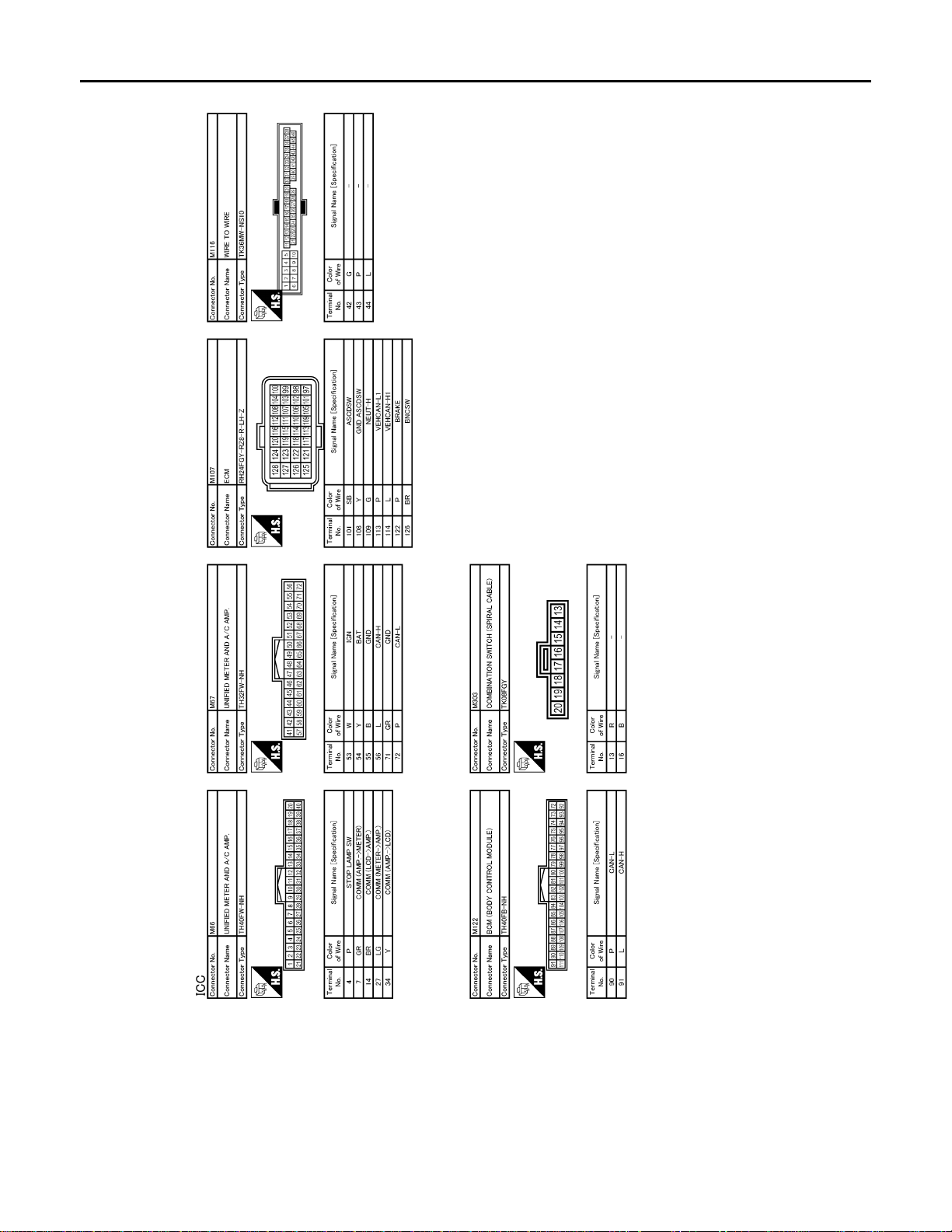
< ECU DIAGNOSIS >
B
Revision: 2007 June G37 Coupe
ICC SENSOR INTEGRATED UNIT
[INTELLIGENT CRUISE CONTROL]
JCOWA0017G
Fail Safe
INFOID:0000000001606950
When a malfunction occurs in ICC system, a chime sounds a beep, the system is released and ICC system
warning lamp in combination meter illuminates. System setting is not accepted when malfunction is detected.
DTC Index INFOID:0000000001606951
CCS-92
×: Applicable
Page 93

< ECU DIAGNOSIS >
Revision: 2007 June G37 Coupe
ICC SENSOR INTEGRATED UNIT
[INTELLIGENT CRUISE CONTROL]
DTC No.
ICC
CONSULT-III
C1A00 0 CONTROL UNIT ×××× CCS-27
C1A01 1 POWER SUPPLY CIR 1 ××××
C1A02 2 POWER SUPPLY CIR 2 ××××
C1A03 3 VHCL SPEED SE CIRC ×××× CCS-30
C1A04 4 ABS/TCS/VDC CIRC ×××× CCS-32
C1A05 5 BRAKE SW/STOP L SW ×××× CCS-34
C1A06 6 OPERATION SW CIRC ××× CCS-44
C1A12 12 LASER BEAM OFFCNTR ×× × CCS-47
C1A13 13 STOP LAMP RLY FIX ×× × CCS-48
C1A14 14 ECM CIRCUIT ×××× CCS-55
C1A15 15 GEAR POSITION ××× CCS-57
C1A16 16 RADAR STAIN ×× × CCS-59
C1A18 18 LASER AIMING INCMP ×× × CCS-61
C1A21 21 UNIT HIGH TEMP ×× × CCS-62
C1A24 24 NP RANGE ××× CCS-63
C1A26 26 ECD MODE MALF ×××× CCS-65
C1A27 27 ECD PWR SUPLY CIR ×××× CCS-67
C1A33 33 CAN TRANSMISSION ERROR ×××× CCS-69
C1A34 34 COMMAND ERROR ×××× CCS-70
NO DTC IS
DETECTED.
FURTHER
TESTING
MA Y BE RE-
QUIRED.
U1000 100 CAN COMM CIRCUIT ×××× CCS-79
U1010 110 CONTROL UNIT (CAN) ×××× CCS-80
U0121 127 VDC CAN CIR2 ×××× CCS-71
U0401 120 ECM CAN CIR1 ×××× CCS-73
U0402 122 TCM CAN CIR1 ×××× CCS-75
U0415 126 VDC CAN CIR1 ×××× CCS-77
On board
display
55
CONSULT-III
screen terms
NO DTC IS DETECTED.
FURTHER TESTING
MAY BE REQUIRED.
system
warning
lamp
———— —
Vehicle-
to-
vehicle
distance
control
mode
Fail-safe
Conven-
tional
(Fixed
speed)
cruise
control
mode
Brake assist (With
preview
function)
Reference page
A
B
C
CCS-28
D
E
F
G
H
I
J
K
L
M
N
CCS-93
CCS
P
Page 94

INTELLIGENT CRUISE CONTROL SYSTEM SYMPTOMS
Revision: 2007 June G37 Coupe
< SYMPTOM DIAGNOSIS >
[INTELLIGENT CRUISE CONTROL]
SYMPTOM DIAGNOSIS
INTELLIGENT CRUISE CONTROL SYSTEM SYMPTOMS
Symptom Table INFOID:0000000001606952
Symptoms Reference page
MAIN switch does not turn ON.
MAIN switch does not switch OFF.
Cruise does not function for setting (powering functions).
Operation
Display/Chime
Control Driving force is hunting.
Function to detect
the vehicle ahead
CANCEL switch does not function.
Resume does not function.
Set speed does not increase.
Set distance to the vehicle ahead cannot be changed.
ICC is not cancelled when the A/T selector lever is “N”.
Multi information display not appear.
Chime does not function.
System frequently cannot detect the vehicle ahead.
Distance to detect the vehicle ahead is short.
System misidentifies a vehicle ev en though there is no vehicle
ahead.
System misidentifies a vehicle in the next lane.
System does not detect a vehicle at all.
Check combination meter . Refe r to MWI-35, "
• Adjust laser beam aiming. Refer to CCS-7,
"LASER BEAM AIMING ADJUSTMENT : Special Repair Requirement (Preparation)".
• Perform ICC action test. Refer to CCS-11,
"ACTION TEST : Special Repair Requirement
(Vehicle-To-Vehicle Distance Contro l Mode)".
Symptom 1
CCS-95
Symptom 2
CCS-97
Symptom 3
CCS-99
Symptom 4
CCS-100
Di-
agnosis Description".
Symptom 5
CCS-102
Symptom 6
CCS-104
Symptom 7
CCS-105
Symptom 8
CCS-106
CCS-94
Page 95

MAIN SWITCH DOES NOT TURN ON, MAIN SWITCH DOES NOT TURN OFF
Revision: 2007 June G37 Coupe
< SYMPTOM DIAGNOSIS >
[INTELLIGENT CRUISE CONTROL]
MAIN SWITCH DOES NOT TURN ON, MAIN SWITCH DOES NOT TURN
OFF
Description INFOID:0000000001606953
MAIN SWITCH DOES NOT TURN ON
• ICC system display does not appear even when MAIN switch is pressed.
MAIN SWITCH DOES NOT TURN OFF
• When ICC system display is on, display does not turn off even if MAIN switch is pressed.
NOTE:
• When ICC system warning lamp is illuminated, ICC system is in fail-safe mode. where ICC system display
will not appear even if MAIN switch is pressed.
• Perform the self-diagnosis for ICC sensor integrated unit if ICC system warning lamp is illuminated. Repair
or replace applicable item.
Diagnosis Procedure INFOID:0000000001606954
1.CHECK MAIN SWITCH
With COUSULT-III
1. Start engine.
2. With “Data Monitor” of “ICC”, check if “MAIN SW” and “CRUISE LAMP” operate normally.
Is the inspection result normal?
YES >> GO TO 2.
NO >> GO TO 5.
2.CHECK UNIFIED METER AND A/C AMP.
With CONSULT-III
With “Data Monitor” of “METER/M&A”, check if “CRUISE IND” operate normally.
Is the inspection result normal?
YES >> GO TO 3.
NO >> GO TO 5.
3.PERFORM SELF-DIAGNOSIS OF UNIFIED METER AND A/C AMP.
1. Perform self-diagnosis of unified meter and A/C amp.
2. Check if DTC is detected. Refer to MWI-100, "DTC Index".
Is any DTC detected?
YES >> Repair or replace applicable item.
NO >> GO TO 4
4.PERFROM SELF-DIAGNOSIS MODE OF COMBINATION METER
A
B
C
D
E
F
G
H
I
J
K
L
M
1. Perform self-diagnosis mode of combination meter. Refer to MWI-35, "
2. Check that the multi information display operates normally.
3. If it does not operate normally, repair the affected components or replace the combination meter.
>> INSPECTION END
Diagnosis Description".
5.PERFORM SELF-DIAGNOSIS OF ICC SENSOR INTEGRA TED UNIT
1. Perform self-diagnosis of ICC sensor integrated unit.
2. Check if DTC “CAN COMM CIRCUIT [U1000]” (DTC 100) is detected.
Is it DTC detected?
YES >> GO TO 6.
NO >> GO TO 7.
6.CAN COMMUNICATION INSPECTION
Perform CAN communication system inspection. Repair or replace the applicable item. Refer to CCS-79,
"Diagnosis Procedure".
CCS-95
N
CCS
P
Page 96

MAIN SWITCH DOES NOT TURN ON, MAIN SWITCH DOES NOT TURN OFF
Revision: 2007 June G37 Coupe
< SYMPTOM DIAGNOSIS >
>> INSPECTION END
[INTELLIGENT CRUISE CONTROL]
7.CHECK ICC STEERING SWITCH
Inspect ICC steering switch. Refer to CCS-44, "
>> INSPECTION END
Diagnosis Procedure"
CCS-96
Page 97

ICC SYSTEM CANNOT BE SET (MAIN SWITCH TURNS ON/OFF)
Revision: 2007 June G37 Coupe
< SYMPTOM DIAGNOSIS >
[INTELLIGENT CRUISE CONTROL]
ICC SYSTEM CANNOT BE SET (MAIN SWITCH TURNS ON/OFF)
Description INFOID:0000000001606955
ICC system cannot be set by pressing SET/COAST switch though MAIN switch can be turned ON/OFF.
NOTE:
ICC system cannot be set in the following cases.
• When the vehicle speed is not in range of approx. 40 km/h (25 MPH) to 144 km/h (90 MPH).
• When the A/T selector lever is in “N” (A/T).
• When the M/T shift knob is set at the neutral position (M/T).
• When the clutch pedal is depressed (M/T).
• While the brake is in operation.
• When the wiper switch is at LOW/HI position.
Diagnosis Procedure INFOID:0000000001606956
1.CHECK CAUSE OF AUTOMATIC CANCELLATION
With CONSULT-III
With “CAUSE OF AUTO-CANCEL” in “Work Support” at “ICC”, check if any cause of cancellation is found.
Is any cause found?
YES >> GO TO 2.
NO >> GO TO 3.
2.CHECK RELEVANT CANCEL FACTORS
Cancel with appropriate cause, and go to specified diagnosis.
A
B
C
D
E
F
G
H
Cancel factor Inspection item
OPE SW VOLT CIRC Refer to CCS-44, "
VHCL SPD UNMATCH Refer to CCS-30, "
IGN LOW VOLT Refer to CCS-28, "
ECM CIRCUIT Refer to CCS-55, "
>> INSPECTION END
Diagnosis Procedure".
Diagnosis Procedure".
Diagnosis Procedure".
Diagnosis Procedure".
3.PERFORM SELFDIAGNOSIS OF ICC SENSOR INTEGRATED UNIT
1. Perform self-diagnosis of ICC sensor integrated unit.
2. Check if DTC is detected. Refer to CCS-92, "DTC Index".
Is any DTC detected?
YES >> GO TO 6.
NO >> GO TO 4.
4.CHECK SWITCHES AND VEHICLE SPEED SIGNAL
With CONSULT-III
1. Start engine.
2. With “Data Monitor” of “ICC”, check the following items for normal operation.
- VHCL SPEED SE
- D RANGE SW (A/T)
- SET/COAST SW
- BRAKE SW
- CLUTCH SW SIG (M/T)
- NP SW SIG (M/T)
Is the inspection result normal?
YES >> GO TO 7.
NO >> GO TO 5.
5.CHECK INOPERATIVE ITEMS
I
J
K
L
M
N
CCS
P
Check the items for which DATA MONITOR cannot operate normally
CCS-97
Page 98

ICC SYSTEM CANNOT BE SET (MAIN SWITCH TURNS ON/OFF)
Revision: 2007 June G37 Coupe
< SYMPTOM DIAGNOSIS >
DATA MONITOR item Inspection item
VHCL SPEED SE Refer to CCS-30, "
D RANGE SW Refer to CCS-100, "
SET/COAST SW Refer to CCS-44, "Diagnosis Procedure".
BRAKE SW
CLUTCH SW SIG
NP SW SIG (M/T) Refer to CCS-82, "
>> INSPECTION END
Refer to CCS-34, "
agnosis Procedure (M/T Models)".
[INTELLIGENT CRUISE CONTROL]
Diagnosis Procedure".
Diagnosis Procedure"
Diagnosis Procedure (A/T Models)" or CCS-38, "Di-
Diagnosis Procedure".
6.REPAIR OR REPLACE APPLICABLE ITEM
Repair or replace applicable item identified by the self-diagnosis result.
>> GO TO 8.
7.REPLACE ICC SENSOR INTEGRATED UNIT
1. Replace ICC sensor integrated unit.
2. Adjust laser beam aiming. Refer to CCS-7, "
Requirement (Preparation)".
LASER BEAM AIMING ADJUSTMENT : Special Repair
>> GO TO 8.
8.CHECK ICC SYSTEM
1. Erase DTC and perform ICC system action test. Then perform self-diagnosis of ICC sensor integrated
unit. (For the details on the ICC system action test, refer to CCS-11, "
Requirement (Vehicle-To-Vehicle Distance Control Mode)").
2. Check that no abnormal condition is present in the ICC system.
>> INSPECTION END
ACTION TEST : Special Repair
CCS-98
Page 99

ICC STEERING SWITCH (OTHER THAN MAIN SWITCH) DOES NOT FUNCTION
Revision: 2007 June G37 Coupe
< SYMPTOM DIAGNOSIS >
[INTELLIGENT CRUISE CONTROL]
ICC STEERING SWITCH (OTHER THAN MAIN SWITCH) DOES NOT
FUNCTION
Description INFOID:0000000001606957
RESUME/ACCELERATE, CANCEL, and DISTANCE switches cannot be operated while ICC system is active
though MAIN switch can be turned ON/OFF.
NOTE:
RESUME does not function in the following cases.
• When MAIN switch is turned OFF once.
• When the vehicle speed is less than 40 km/h (25 MPH).
Diagnosis Procedure INFOID:0000000001606958
1.CHECK ICC STEERING SWITCHES
With CONSULT-III
1. Start engine.
2. With “Data Monitor” of “ICC”, check if ICC steering switches operate normally.
- “RESUME/ACC SW”
- “CANCEL SW”
- “DISTANCE SW”
Is the inspection result normal?
YES >> GO TO 5.
NO >> GO TO 2.
2.PERFORM SELF-DIAGNOSIS OF ICC SENSOR INTEGRA TED UNIT
A
B
C
D
E
F
G
H
1. Perform self-diagnosis of ICC sensor integrated unit.
2. Check if DTC “CAN COMM CIRCUIT [U1000]” (DTC 100) is detected.
Is it DTC detected?
YES >> GO TO 3.
NO >> GO TO 4.
3.CAN COMMUNICATION INSPECTION
Perform CAN communication system inspection. Repair or replace applicable item. Refer to CCS-79,
"Diagnosis Procedure".
>> INSPECTION END
4.ICC STEERING SWITCH INSPECTION
Inspect ICC steering switch. Refer to CCS-46, "
>> INSPECTION END
Component Inspection".
5.REPLACE ICC SENSOR INTEGRATED UNIT
1. Replace ICC sensor integrated unit.
2. Adjust laser beam aiming. Refer to CCS-7, "
Requirement (Preparation)".
>> GO TO 6.
LASER BEAM AIMING ADJUSTMENT : Special Repair
6.CHECK ICC SYSTEM
I
J
K
L
M
N
CCS
P
1. Erase DTC and perform ICC system action test. Then perform self-diagnosis of ICC sensor integrated
unit. (For the details on the ICC system action test, refer to CCS-11, "
Requirement (Vehicle-To-Vehicle Distance Control Mode)").
2. Check that no abnormal condition is present in the ICC system.
>> INSPECTION END
ACTION TEST : Special Repair
CCS-99
Page 100

ICC SYSTEM DOES NOT CANCEL WHEN A/T SELECTOR LEVER SETS ON "N"
Revision: 2007 June G37 Coupe
< SYMPTOM DIAGNOSIS >
[INTELLIGENT CRUISE CONTROL]
ICC SYSTEM DOES NOT CANCEL WHEN A/T SELECTOR LEVER SETS
ON "N"
Description INFOID:0000000001606959
ICC system is not canceled even when the A/T selector lever is shifted to the “N” range while ICC system is
active.
Diagnosis Procedure INFOID:0000000001606960
1.CHECK INPUT “D” RANGE SWITCH SIGNAL (ICC SENSOR INTEGRATED UNIT)
With CONSULT-III
1. Start engine.
2. With “Data Monitor” of “ICC”, check if “D RANGE SW” and “NP RANGE SW” operate normally.
Is the inspection result normal?
YES >> GO TO 6.
NO >> GO TO 2.
2.PERFORM SELF-DIAGNOSIS OF ICC SENSOR INTEGRATED UNIT
1. Perform self-diagnosis of ICC sensor integrated unit.
2. Check if DTC “CAN COMM CIRCUIT [U1000]” (DTC 100) is detected.
Is it DTC detected?
YES >> GO TO 3.
NO >> GO TO 4.
3.CAN COMMUNICATION INSPECTION
Perform the CAN communication system inspection. Repair or replace the applicable item. Refer to CCS-79,
"Diagnosis Procedure".
>> INSPECTION END
4.CHECK INPUT “D” RANGE SWITCH SIGNAL (TCM)
With CONSULT-III
With “Data Monitor” of “A/T”, check if “SLCT LVR POSI” operates normally.
Is the inspection result normal?
YES >> GO TO 6.
NO >> GO TO 5.
5.RERFORM SELF-DIAGNOSIS OF TCM
1. Perform self-diagnosis of TCM.
2. Repair or replace applicable item. Refer to EC-552, "
>> GO TO 7.
DTC Index".
6.PEPLACE ICC SENSOR INTEGRATED UNIT
1. Replace ICC sensor integrated unit.
2. Adjust laser beam aiming. Refer to CCS-7, "
Requirement (Preparation)".
>> GO TO 7.
LASER BEAM AIMING ADJUSTMENT : Special Repair
7.CHECK ICC SYSTEM
1. Erase DTC and perform ICC system action test. Then perform self-diagnosis of ICC sensor integrated
unit. (For the details on the ICC system action test, refer to CCS-11, "
Requirement (Vehicle-To-Vehicle Distance Control Mode)").
2. Check that no abnormal condition is present in the ICC system.
ACTION TEST : Special Repair
CCS-100
 Loading...