

Page 1
®
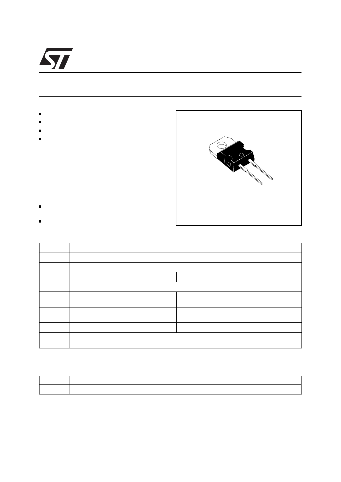
FAST RECOVERY RECTIFIER DIODE
VERY HIGH REVERSE VOLTAGE CAPABILITY
VERY LOW REVERSES RECOVERY TIME
VERY LOW SWITCHING LOSSES
LOW NOISE T URN- OF F SWITCHING
BYT 08P-1000
Cathode connected to case
A
K
SUITAB L E A PPLICATIONS
FREE WHEELING DIODE IN CONVERTERS
TO220AC
(Plastic)
AND MOTOR CONTROL CIRCUITS
RECTIFIER IN S.M.P.S.
ABSOLUTE RATINGS
Symbol Parameter Value Unit
V
RRM
V
RSM
I
FRM
I
F (RMS)
I
F (AV)
I
FSM
P Power Dissipation
T
stg
T
Repetitive Peak Reverse Voltage 1000 V
Non Repetitive Peak Reverse Voltage 1000 V
Repetitive Peak Forward Current
RMS Forward Current 16 A
Average Forward Current Tc = 115°C
Surge Non Repetitive Forward Current tp = 10ms
Storage and Junction Temperature Range - 40 to + 150
j
(limiting values)
≤ 10µs
t
p
= 0.5
δ
Sinusoidal
= 115°C
T
c
100 A
8A
50 A
17 W
- 40 to + 150
C
°
THERMAL R E SI STANCE
Symbol Parameter Value Unit
R
th (j - c)
October 1999 - Ed: 2A 1/4
Junction-case 2
C/W
°
Page 2
BYT 08P-1000
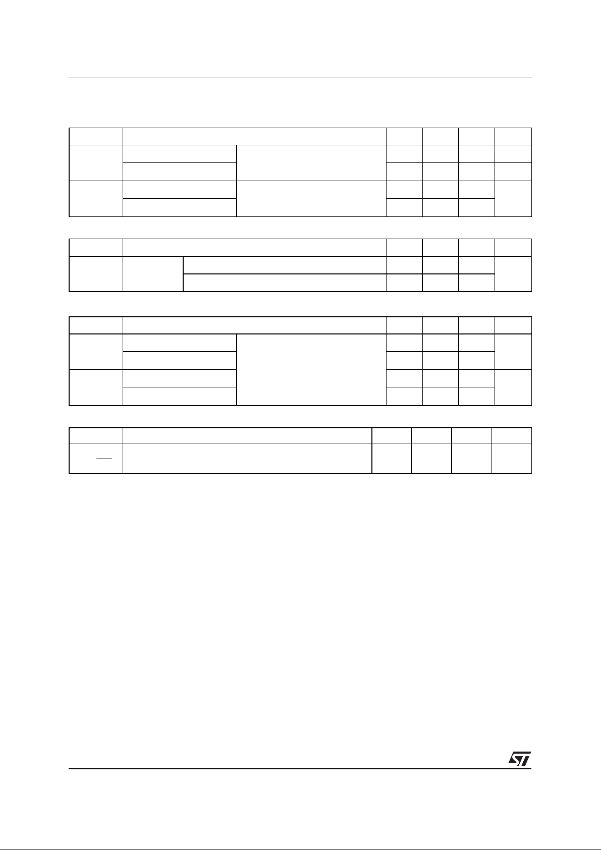
ELECTRICAL CHARACTERISTICS
STATIC C HAR ACTERISTICS
Synbol Test Conditions Min. Typ. Max. Unit
V
I
R
V
F
Tj = 25°C
= 100°C
T
j
T
= 25°C
j
= 100°C
T
j
= V
R
RRM
2mA
I
= 8A 1.9
F
1.8
RECO V ERY CHARACTERISTICS
Symbol Test Conditions Min. Typ. Max. Unit
t
rr
I
Tj = 25°CI
= 1A diF/dt = - 15A/µs VR = 30V
F
= 0.5A IR = 1A Irr = 0.25A 65
F
TURN-OFF SWITCHING CHARACTERISTICS (Without Series Inductance)
Symbol Test Conditions Min. Typ. Max. Unit
35
155
µ
ns
A
V
t
IRM
I
RM
diF/dt = - 32A/µs
/dt = - 64A/µs
di
F
diF/dt = - 32A/µs
/dt = - 64A/µs
di
F
V
= 200 V IF = 8A
CC
L
0.05µH T
≤
p
See Figure 1
= 100°C
j
200 ns
120
5.5 A
6
TURN-OFF OVERVOLTAGE COEFFICIENT (With Series Inductance)
Symbol Test Conditions Min. Typ. Max. Unit
V
C =
RP
Tj = 100°C VCC = 200V IF = I
V
diF/dt = - 8A/µs Lp = 12µH See figure 2
CC
F (AV)
4.5
To evaluate the conduction losses use the following equations:
V
= 1.47 + 0.041 IF P = 1.47 x I
F
F(AV)
+ 0.041 I
F2(RMS)
2/4
Page 3

Figure 1. Turn-off switching characteristics (without series inductance).
Figure 2. Turn-off switching characteristics (with series inductance).
BYT 08P-1000
3/4
Page 4

BYT 08P-1000
PACKAGE MECHANICAL DATA :
H2
L5
Ø I
L6
L2
L9
F1
L4
F
G
TO220AC Plastic
A
C
L7
D
M
E
DIMENSIONS
REF.
Millimeters Inches
Min. Max. Min. Max.
A 4.40 4.60 0.173 0.181
C 1.23 1.32 0.048 0.051
D 2.40 2.72 0.094 0.107
E 0.49 0.70 0.019 0.027
F 0.61 0.88 0.024 0.034
F1 1.14 1.70 0.044 0.066
G 4.95 5.15 0.194 0.202
H2 10.00 10.40 0.393 0.409
L2 16.40 typ. 0.645 typ.
L4 13.00 14.00 0.511 0.551
L5 2.65 2.95 0.104 0.116
L6 15.25 15.75 0.600 0.620
L7 6.20 6.60 0.244 0.259
L9 3.50 3.93 0.137 0.154
M 2.6 typ. 0.102 typ.
Diam. I 3.75 3.85 0.147 0.151
Cooling method: by conduction (method C)
Marking: type number
Weight: 2.42g
Recommended torque value: 80cm. N
Maximum torque value: 100cm. N
Information furnished is believed to be accurate and reliable. Howev er, STMicroelectronics assumes no responsibility for the consequences of
use of such information nor for any infringement of patents or othe r ri ght s of thir d parties which may result from its use. No license is granted
by implication or otherwise under any patent or patent rights of STMicroelectronics. Specifications mentioned in this publication are subject to
change without notice. This publication supersedes and replaces all information previously supplied.
STMicroelectronics products are not authorized for use as critical components in life support devices or systems without express written approval
of STMicroelectronic s.
The ST logo is a registered trademark of STMicroelectronics
© 1999 STMicroelectronics - Printed in Italy - All rights reserved.
Australia - Brazil - China - Finland - France - Germany - Hong Kong - India - Italy - Japan - Malaysia
Malta - Morocco - Singapore - Spain - Sweden - Switzerland - United Kingdom - U.S.A.
STMicroelectronics GROUP OF COMPANIES
http://www.st.com
4/4
 Loading...