

Page 1
Audio ICs
PLL frequency synthesizer for tuners
BU2618FV
The BU2618FV is a low current dissipation PLL frequency synthesizer designed for use in FM multiplex radio receiver
and FM pager receiver. Featuring very small package and built-in prescaler that can operate at up to 130MHz.
Applications
FM multiplex radio receivers, pagers, radios, and other
signal generators
Features
1) Built-in high-speed prescaler can divide 130
MHzVCO.
2) Low current dissipation (during operation: 1.5mA,
PLL OFF: 200µA Typ.)
3) Seven standard frequencies: 25kHz, 12.5kHz,
6.25kHz, 10kHz, 9kHz, 5kHz, and 1kHz.
4) Counter for intermediate frequency detection.
5) Unlock detection circuit.
6) Four output ports.
7) Serial data input (CE, CK, DA)
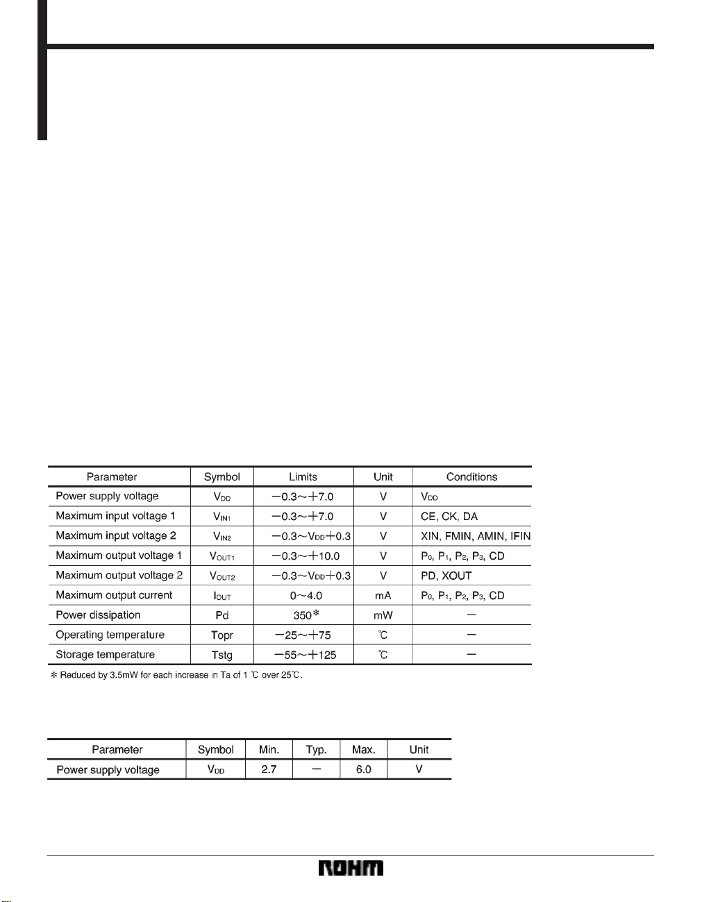
Absolute maximum ratings (Ta = 25C)
Recommended operating conditions (Ta = 25C)
139
Page 2
Audio ICs BU2618FV
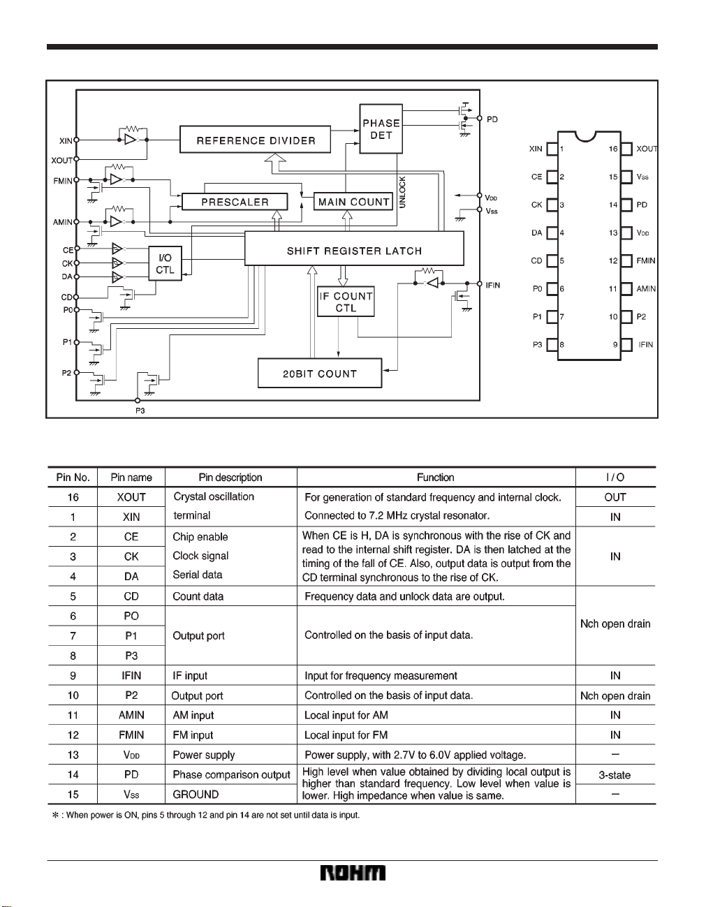
Block diagram
Pin descriptions
140
Page 3
Audio ICs BU2618FV
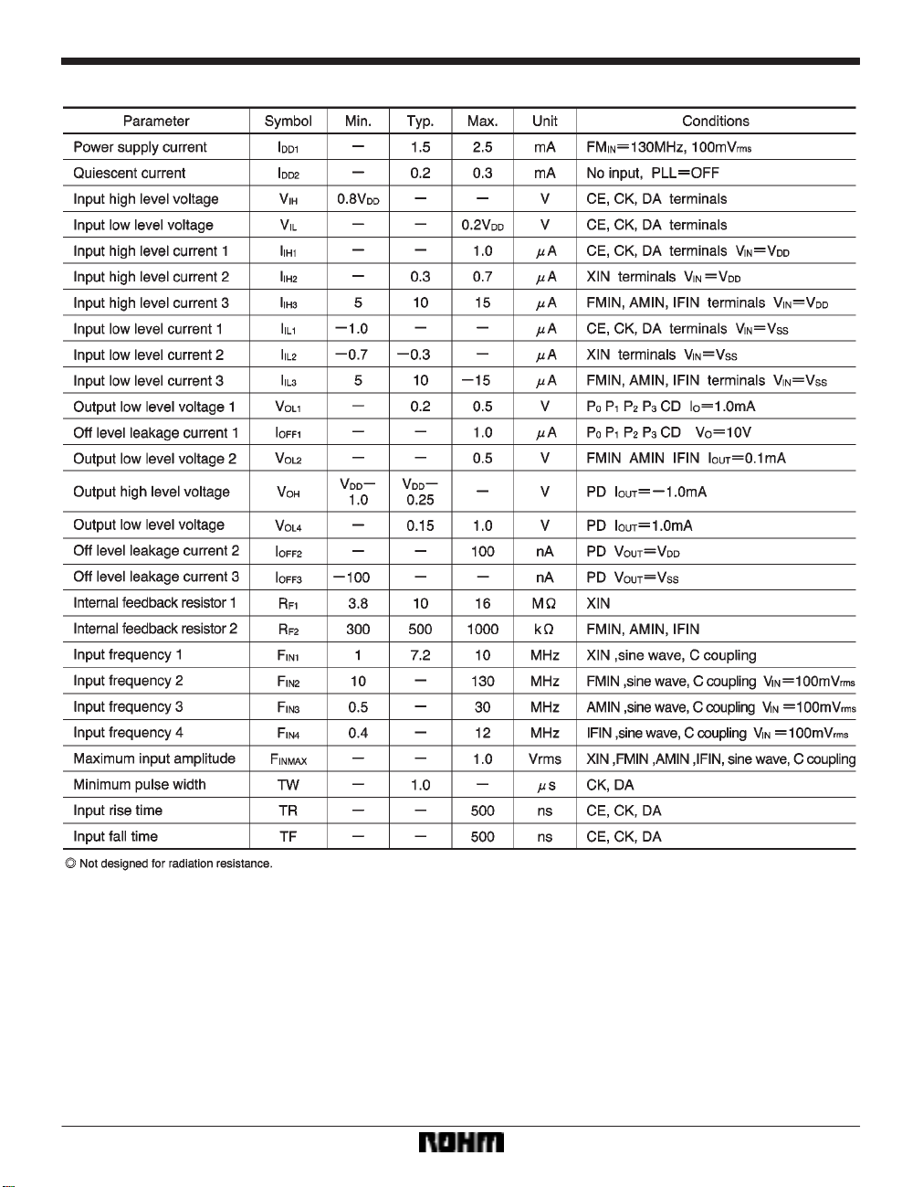
Electrical characteristics (unless otherwise noted, Ta = 25C, VDD = 3.0V)
141
Page 4

Audio ICs BU2618FV
Circuit operation
142
Page 5

Audio ICs BU2618FV
Explanation of the data
(1) Division data: For D
(2) CT: Frequency measurement beginning data
1: Begins measurement.
0: Resets internal counter, IFIN goes to pulldown.
(3) Output port control data:
1: Open drain output ON
2: Open drain output OFF
(4) R
0, R1, R2, standard frequency data
0 through D15 (When S = 0, use D4 through D15.)
(5) S: switch between FMIN and AMIN
0: FMIN 1: AMIN
(6) PS: If this bit is set to ON while AMIN is selected,
swallow counter division is possible.
(7) GT: Frequency measurement time and unlock detection ON/OFF
(8) TS: Test data (0) is input
143
Page 6

Audio ICs BU2618FV
Frequency counter
(1) Structure
(2) How the frequency counter operates
When control data CT equals 1, the 20-bit counter
and the amp go into operation. When CT equals 0,
amp input goes to pulldown and the counter is reset. Measuring time (gate pulse) is selected
(16ms / 32ms) on the basis of control data GT.
When control data CT equals 0, the counter is reset.
(3) Explanation of output data
D
0: LSB D19: MSB
Unlock detection
When control data GT equals 1, or CT equals 1, the
unlock detection circuit goes into operation for 8 ms.
When CT equals 1, the unlock detection circuits
stops operating before the frequency counter gate
pulse is emitted. When CT equals 0, or GT equals
0, the unlock detection circuit is reset.
144
Page 7

Audio ICs BU2618FV
Frequency counter and unlock detection
(1) When CT = 1: Frequency count and unlock detection are carried out.
(2) When CT = 0 and GT = 1: Only unlock detection is carried out.
Explanation of CD
When frequency measurement or unlock detection is finished, the CD terminal goes to LO to indicate that the
count and unlock detection have finished. It also synchronizes with CK to output counter data. When the next
data is input, it goes to HI.
145
Page 8

Audio ICs BU2618FV
Electrical characteristics curves
External dimensions (Units: mm)
146
 Loading...