

Page 1
Audio ICs
PLL frequency synthesizer for tuners
BU2614 / BU2614FS
The BU2614 PLL frequency synthesizers work up through the FM band. Featuring low radiation noise, low power dissipation, and highly sensitive built-in RF amps, they support an IF count function.
Applications
Tuners (Mini components, radio cassette players, radio
equipment, etc.)
Features
1) Built-in high-speed prescaler can divide 130MHzVCO.
2) Reference oscillation of 75kHz keeps unnecessary
radiation noise to a low level.
3) Low current dissipation (during operation: 4mA, PLL
OFF 100µA).
4) In addition to the standard FM and AM, also offers the
following 7 frequencies: 25kHz, 12.5kHz, 6.25kHz,
3.125kHz, 5kHz, 3kHz, and 1kHz.
5) Counter for measurement of intermediate frequencies.
6) Unlock detection.
7) Three output ports (open drain).
The BU2615, with seven output ports, is also available.
8) Serial data input (CE, CK, DA).
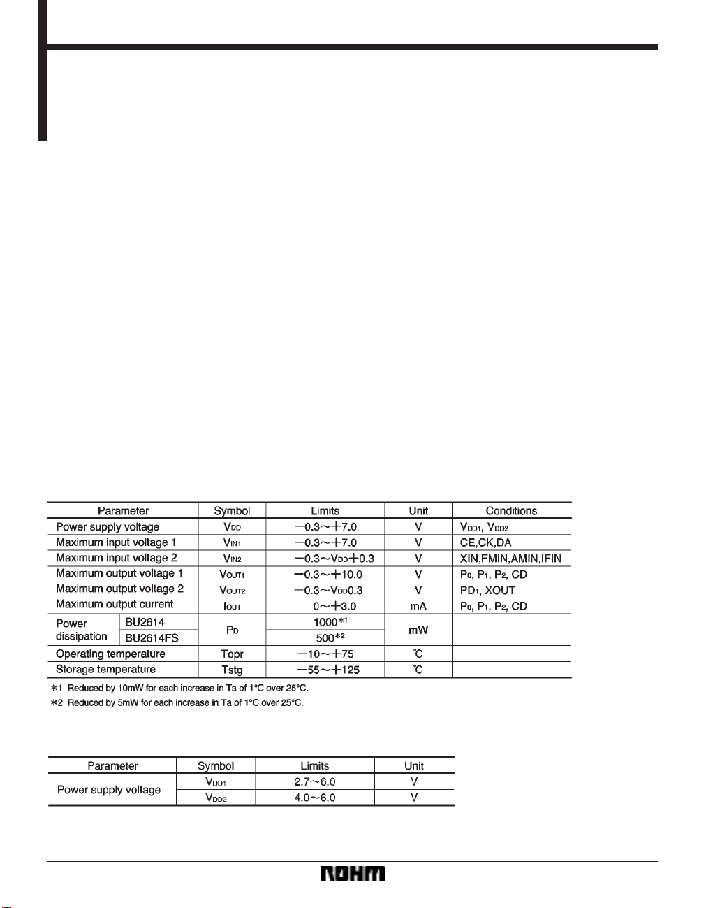
Absolute maximum ratings (Ta = 25C)
Recommended operating conditions (Ta = 25C)
116
Page 2
Audio ICs BU2614 / BU2614FS
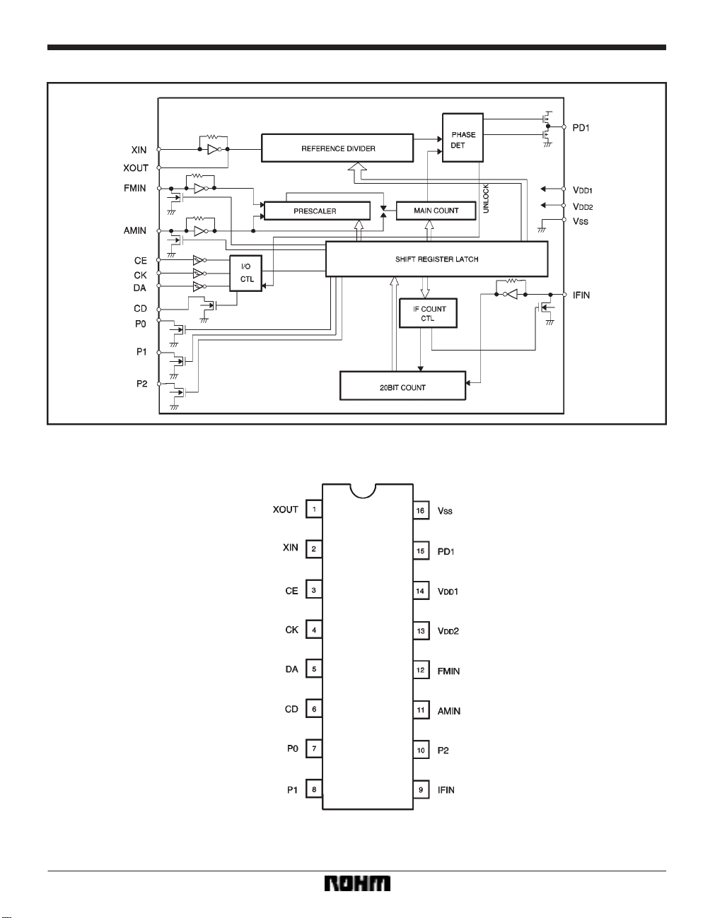
Block diagram
Pin assignments
117
Page 3
Audio ICs BU2614 / BU2614FS
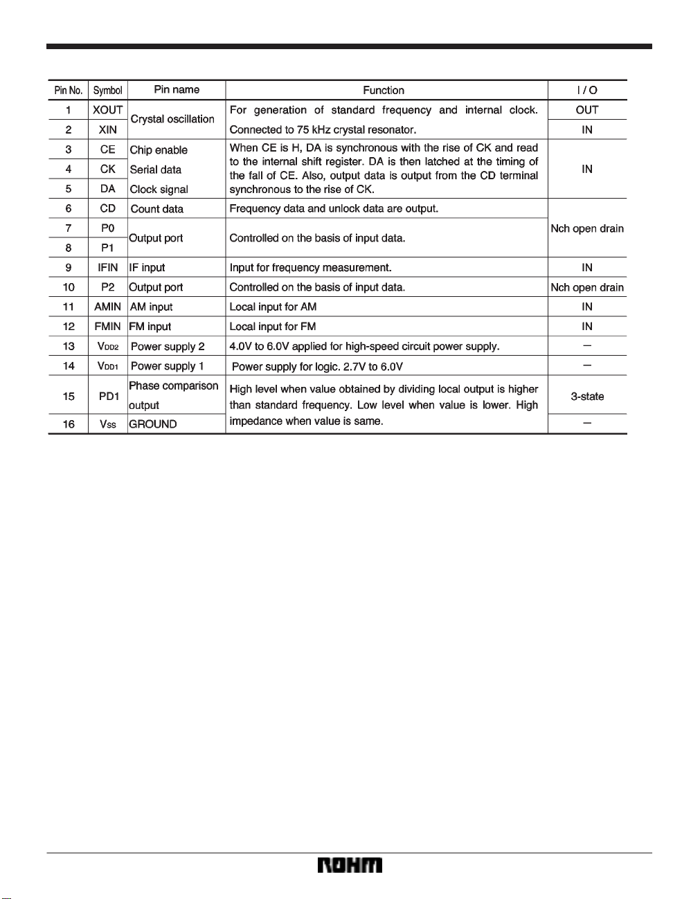
Pin descriptions
118
Page 4

Audio ICs BU2614 / BU2614FS
Electrical characteristics (unless otherwise noted, Ta = 25C, VDD1 = VDD2 = 5.0V)
119
Page 5

Audio ICs BU2614 / BU2614FS
Input data format
120
Page 6

Audio ICs BU2614 / BU2614FS
Explanation of the data
(1) Division data: For D
(2) CT: Frequency measurement beginning data
1: Beginning of measurement
0: Internal counter is reset, IFIN is pulldown.
(3) Output port control data: P0, P1, P2
1: Open drain output ON
2: Open drain output OFF
(4) R
0, R1, R2, standard frequency data
0 through D15 (When S = 1, use D4 through D15.)
(5) S: switch between FMIN and AMIN 0: FMIN
1: AMIN
(6) PS: If this bit is set to ON while AMIN is selected,
swallow counter division is possible.
(7) GT: Frequency measurement time and unlock
detection ON/OFF
(8) TS: Test data (0) is input.
121
Page 7

Audio ICs BU2614 / BU2614FS
Frequency counter
(1) Structure
(2) How the frequency counter operates
When control data CT equals 1, the 20-bit counter and
the amp go into operation. When CT equals 0, input pulldown and the counter are reset. Measuring time (gate
pulse) is selected (16ms /32ms) on the basis of control
data GT. When control data CT equals 0, the counter is
reset.
How the unlock detection circuit operates
When control data GT equals 1, or CT equals 1, the unlock detection circuit goes into operation for 8ms. When
CT equals 1, the unlock detection circuits stops operating
before the frequency counter gate pulse is emitted.
(3) Explanation of output data
D
0: LSB D19: MSB
When CT equals 0, or GT equals 0, the unlock detection
circuit is reset.
122
Page 8

Audio ICs BU2614 / BU2614FS
How the frequency counter and unlock detection circuit operate
(1) When CT = 1: Frequency count and unlock detection are carried out.
(2) When CT = 0 and GT = 1: Only unlock detection is
carried out.
Explanation of CD terminal
When frequency measurement or unlock detection is finished, the CD terminal goes to LO to indicate that the
count and unlock detection have finished.
It also synchronizes with CK to output counter data.
When the next data is input, it goes to HI.
123
Page 9

Audio ICs BU2614 / BU2614FS
External dimensions (Units: mm)
124
 Loading...