

Page 1
Optical disc ICs
4-channel BTL driver for CD players
BA6997FP / BA6997FM
The BA6997FP and BA6997FM, both designed for CD players, have an internal 4-channel BTL driver and 5V regulator
(which requires attached PNP transistor), as well as switches for the 5V regulator and temperature monitor pins.
Applications
CD players and other optical disc devices
Features
1) 4-channel BTL driver for CD players.
2) Wide dynamic range.
3) Internal thermal shutdown circuit.
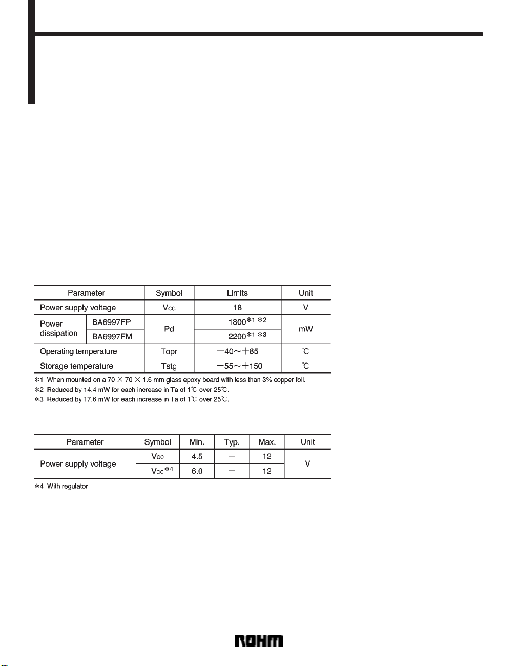
Absolute maximum ratings (Ta = 25C)
4) Internal level shift circuit, for a minimum of attached
components.
5) Internal 5V regular with switch.
Recommended operating conditions (Ta = 25C)
403
Page 2

Optical disc ICs BA6997FP/BA6997FM
Block diagram
404
Page 3
Optical disc ICs BA6997FP/BA6997FM
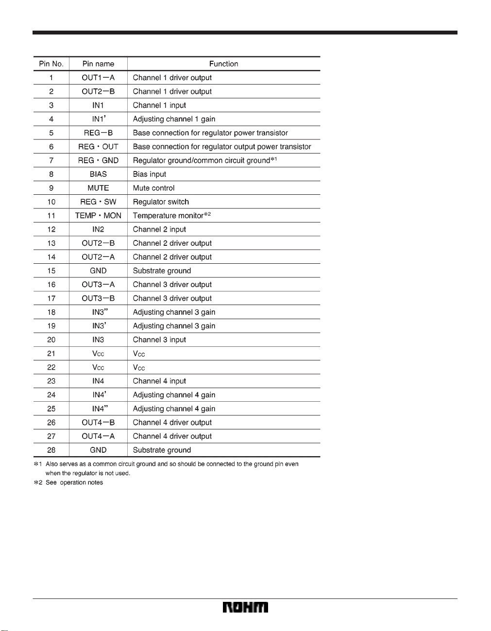
Pin descriptions
405
Page 4

Optical disc ICs BA6997FP/BA6997FM
Electrical characteristics (unless otherwise noted, Ta = 25C, VCC = 8V, f = 1kHz, RL = 8Ω)
406
Page 5

Optical disc ICs BA6997FP/BA6997FM
Application example
407
Page 6

Optical disc ICs BA6997FP/BA6997FM
Operation notes
(1) The BA6997FP and BA6997FM have an internal
thermal shutdown circuit. Output current is muted when
the chip temperature exceeds 175C (typically).
(2) The output current can be muted by opening the
mute pin (pin 9) voltage or lowering it below 0.5V . This pin
should be pulled up above 2.0V during normal operation.
When muting occurs, the output pins output the internal
bias voltage, roughly V
(3) The regulator can be turned off by opening the regulator switch (pin 10) or lowering it below 0.5V. This pin
should be pulled up above 2.0V during normal operation.
(4) Muting also occurs when the bias pin (8 pin) voltage
drops below 1.4V (typically). This pin should stay above
1.6V during normal operation.
(5) Attach a bypass capacitor (roughly 0.1µF) to the
power supply, at the base of the IC.
(6) Be sure to connect the radiating fin to an external
ground.
CC/2.
(7) The capacitor between regulator output (pin 6) and
REGGND (pin 7) also serves to prevent oscillation of the
IC, so select one with good temperature characteristics.
(8) We recommend 2SB1 132 as the PNP transistor to
attach to the regulator.
(9) The internal circuitry of the temperature monitor pin
is shown in the diagram below. Note that the internal reference voltage is also used for the 5V regulator, which
will cease to operate normally when the temperature
monitor pin emits a current exceeding the regulator’s capacity. Set I to several dozen µA.
Electrical characteristic curves
408
Page 7

Optical disc ICs BA6997FP/BA6997FM
External dimensions (Units: mm)
409
 Loading...