

Page 1

Motor driver ICs
Voice coil motor driver
BA6832FS
The BA6832FS is a voice coil motor driver used for moving the heads of hard disc and mass-storage floppy disc drives.
Applications
HDD disc and mass-storage FDD
Features
1) Output current is controlled by the Vctl-Vref voltage.
2) Retraction control pin.
Absolute maximum ratings (Ta = 25C)
3) Chip enabling pin.
4) Internal thermal shutdown circuit.
Recommended operating conditions
509
Page 2
Motor driver ICs BA6832FS
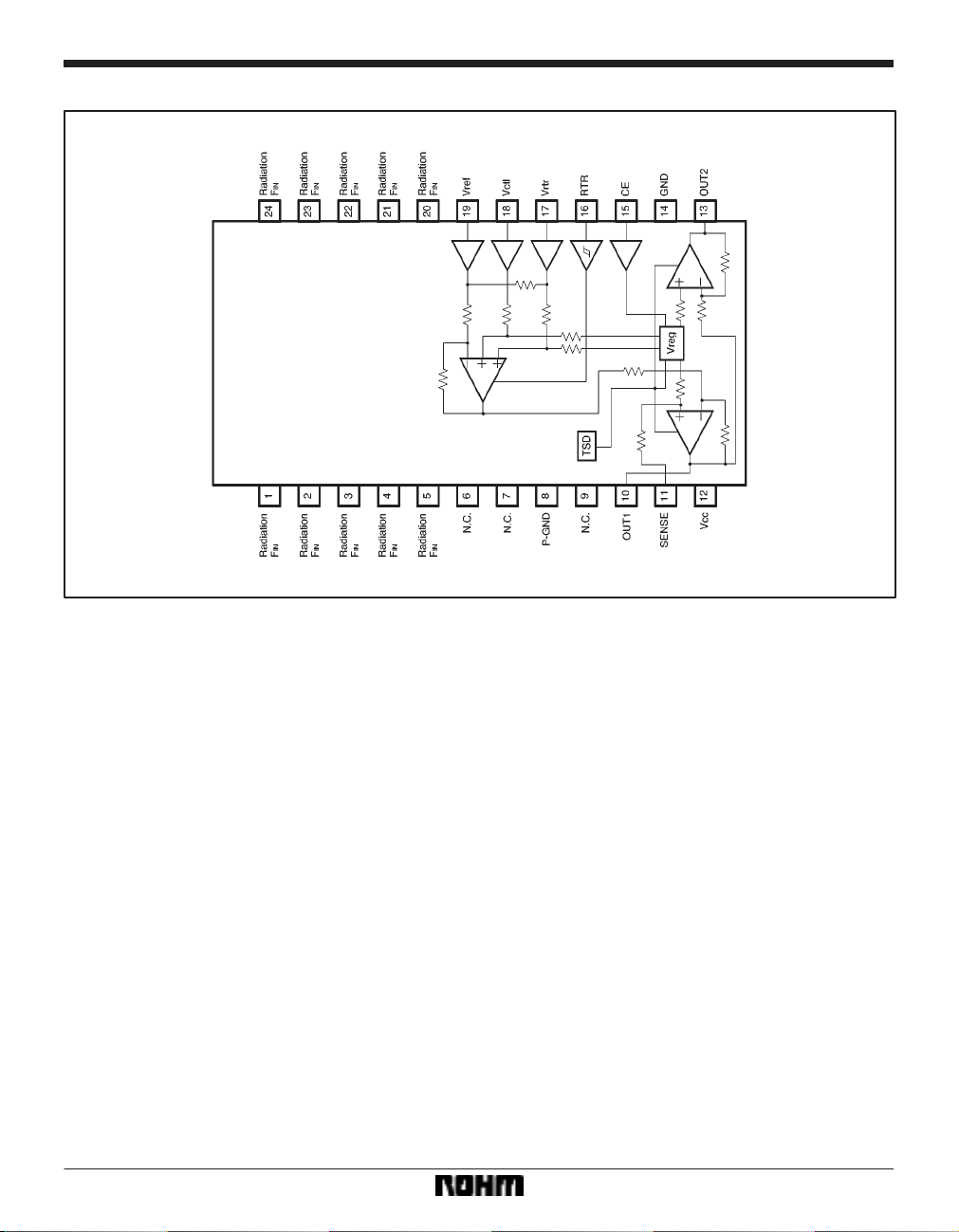
Block diagram
510
Page 3

Motor driver ICs BA6832FS
Pin descriptions
Input / output circuits
511
Page 4

Motor driver ICs BA6832FS
Electrical characteristics (unless otherwise noted, Ta = 25C and VCC = 12V)
512
Page 5

Motor driver ICs BA6832FS
Circuit operation
(1) Output current control
The method of output current control depends on whether the RTL pin is HIGH or LOW.
(1) When the RTL pin is LOW
The voltage V
tween pins 10 and 11 (with reference to pin 10) is controlled by the voltage between Vctl (pin 18) and Vref (pin
19) :
V
RS=(VctlVref)1 (Typ.)
The output current I
O=(VctlVref) / Rs (Typ.)
I
where the positive direction is from pin 13 to pin 10.
Therefore, the voltage-current conversion gain for the
control input is determined by the R
band width in this case is 80kHz (typical).
(2) When the RTL pin is HIGH
The V
the Vrtr (pin 17) voltage (with reference to the ground) :
RS=0.1Vrtr / Rs
V
(3) RTR threshold
The RTR pin threshold voltage is 1.21.3V . The pin has
a hysteresis width of about 40mV.
(2) Standby mode
The standby mode is activated when the CE pin is LOW;
the circuit current is reduced to 0.15mA (typical), and the
output pins are put to the high impedance state. The operation mode is activated when the CE pin is HIGH, and
the output current becomes controllable. The pin’s
threshold voltage is 1.21.3V.
(3) Internal reference voltage
The internal reference voltage V
reg=(VCCVF)/2
V
where V
and 13) operate with reference to V
RS that develops across the resistor RS be-
O is given by :
S value. The gain
RS voltage (with reference to pin 10) is controlled by
reg is given by :
reg=5.65 when VCC=12V . The output pins (pins 10
reg.
513
Page 6

Motor driver ICs BA6832FS
Application example
514
Page 7

Motor driver ICs BA6832FS
Operation notes
(1) Thermal shutdown circuit
The IC has a built-in thermal shutdown circuit. The circuit
turns off all the driver outputs when the chip junction temperature rises to about 175C (typical). There is a temperature difference of 20C (typical) between the temperatures at which the circuit is activated and
deactivated.
(2) Vctl, Vref, and input pins
If voltage is applied to Vctl (pin 18) and V
CC voltage is outside the operating voltage, the driv-
the V
ref (pin 19) when
er outputs are turned on and a current may flow through
the connected motor. The voltage of each input pin
should be less than V
CC and more than the ground volt-
age.
Electrical characteristic curves
(3) Temperature dependence of quiescent circuit current (I
CC)
When the IC temperature rises with Vctl=V
CE=LOW in the quiescent mode, I
CC may increase due
ref and
to the temperature dependence of the standby current
that flows through the high- and low-side transistors.
(4) Package power dissipation
The IC power dissipation changes greatly with the supply
voltage and the output current. Give full consideration to
the power dissipation rating when setting the supply voltage and the output current.
515
Page 8

Motor driver ICs BA6832FS
External dimensions (Units: mm)
516
 Loading...