

Page 1
Audio ICs
Fluorescent display tube level meter
driver, 12-point 2 channel, VU scale,
bar display
BA6810F
The BA6810F is a two-channel, 12-point fluorescent display tube driver for VU-scale bar-level meters.
It uses a dynamic-drive system and has both AC and DC inputs. The AC input mode has a peak hold circuit. The IC
features a power-on mute, and the output block can directly drive fluorescent display tubes, so few external components
are required, allowing cost and space savings while improving reliability. The grid output duty cycle is 1/8.
Applications
Level meters for all types of AV equipment
Features
1) Uses dynamic-drive system to display two 12-point
channels. 28-pin SOP package.
2) AC and DC inputs provided. Switching function allows two-mode display .
3) Upper 8 points have peak hold function in AC mode
(two seconds typ.).
4) Power-on mute function.
5) Forced-mute function.
6) Terminal for meter sensitivity adjustment provided
(adjustment with one terminal is possible).
2
7) I
L injector current terminal provided.
8) Square root compression amplifier built in.
9) Dynamic-drive system reduces the power dissipation of the fluorescent display tube power supply.
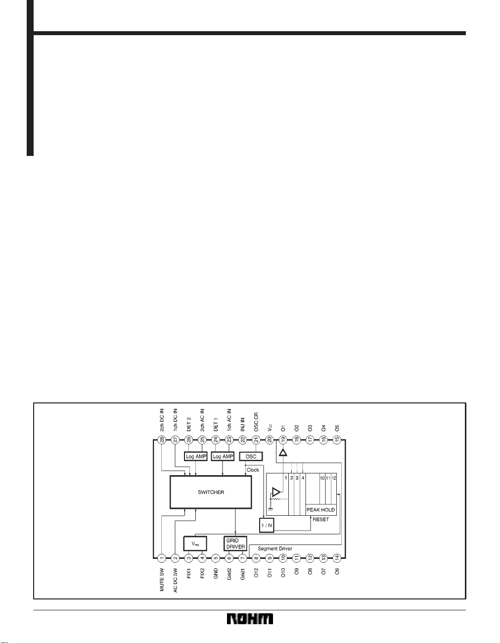
Block diagram
790
Page 2
Audio ICs BA6810F
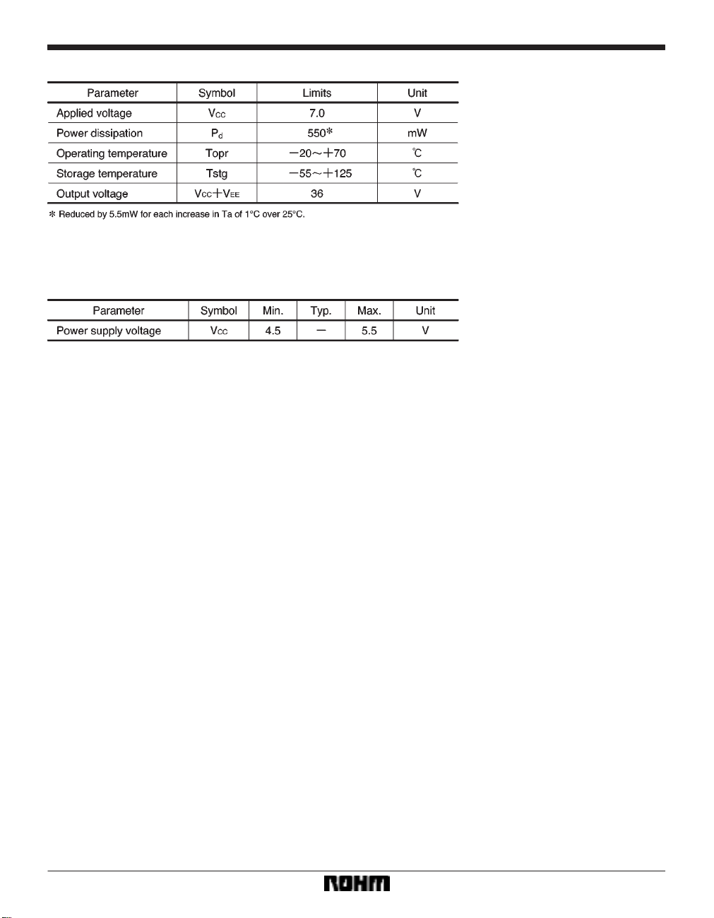
FAbsolute maximum ratings (Ta = 25_C)
FRecommended operating conditions
791
Page 3
Audio ICs BA6810F
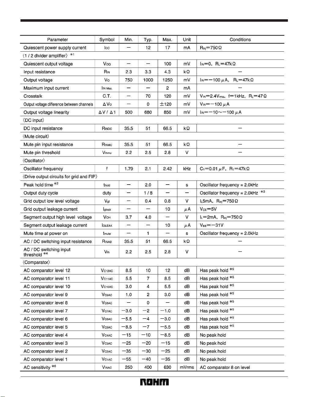
FElectrical characteristics (unless otherwise noted, Ta = 25_C and VCC = 5.0V)
792
Page 4

Audio ICs BA6810F
793
Page 5

Audio ICs BA6810F
Measurement circuit
Application example
794
Page 6

Audio ICs BA6810F
Circuit operation
(1) Input block
The AC input pins are pins 23 and 25, and the DC input
pins are pins 27 and 28. Pin 2 is used to switch between
the AC and DC inputs. When the input to pin 2 is “H”, AC
input is selected (pins 23 and 25). Therefore, by using pin
2 to switch between the AC and DC modes, the IC can
do two jobs, using one fluorescent tube. For example,
pins 23 and 25 can be used for audio signal input, and
pins 27 and 28 can be used as the input for the signal meter output from a tuner (DC).
(2) Peak hold circuit
The BA6810F features a peak hold circuit that temporarily holds peak signal levels in AC input mode.
The peak hold function can be used with the upper 8
points (5 to 12). The peak hold time depends on the oscillator frequency . It is 2 sec. (typ.) for an oscillator frequency of 2kHz.
(3) MUTE function
The display can be turned off by driving the MUTE terminal “H”.
(4) Meter sensitivity adjustment terminal
Connect a potentiometer of about 10kΩ, and adjust it so
that the 8th point lights when the for an AC input of
400mV
rms. The dispersion between left and right chan-
nels is "1.0dB.
(7) Grid and segment output timing chart.
The grid and segment output timing is shown in Fig. 6.
(5) Grid output
The pin 6 and 7 grid outputs are open-collector NPN transistors. The logic is active low (the fluorescent tube lights
when the output is “L”), so connect two PNP transistors
Q
1 and Q2 as shown in the application example circuit to
drive the fluorescent tubes (see Fig. 4).
(6) Segment output block
Pins 8 to 19 are the segment outputs. The output circuits
are open-collector PNP transistors. When grid 1 is “L”,
the ch1 level is output (pin 23 or 27 input level), and when
grid 2 is “L”, the ch2 level is output (pin 25 or 28 input level). Refer to Fig. 5.
(8) Attack and recovery times
The output response characteristic for AC input signals
is set by pins 24 and 26. The comparator level may
change somewhat due to the sag of the CR circuit discharge.
(9) Oscillator frequency
The resistor and capacitor connected to pin 21 determine
the oscillator frequency. The oscillator frequency (f
osc)
and grid output period (T) are related as follows:
795
Page 7

Audio ICs BA6810F
Electrical characteristics curves
External dimensions (Units: mm)
796
 Loading...