

Page 1
Audio ICs
Fluorescent display tube level meter
driver, 16-point 2 channel, VU scale,
bar display
BA6800AS
The BA6800AS is a two-channel, 16-point fluorescent display tube driver for VU-scale bar-level meters. It uses a dynamic-drive system and has both AC and DC inputs. The AC input mode has a peak hold circuit. The IC features a power-on
mute, and the output block can directly drive fluorescent display tubes, so few external components are required. The
grid output duty cycle is 1 / 8.
Applications
Level meters for all types of AV equipment
Features
1) Uses dynamic-drive system to display two 16-point
channels. 30-pin SDIP package.
2) AC and DC inputs provided. Switching function allows two-mode display .
3) Upper 12 points have peak hold function in AC mode
(two seconds).
4) Power-on mute function.
5) Dynamic-drive system reduces the power dissipation of the fluorescent display tube power supply.
6) Square root compression amplifier built in.
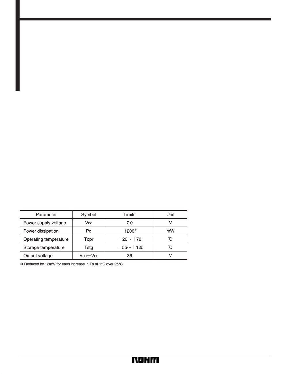
Absolute maximum ratings (Ta = 25C)
797
Page 2
Audio ICs BA6800AS
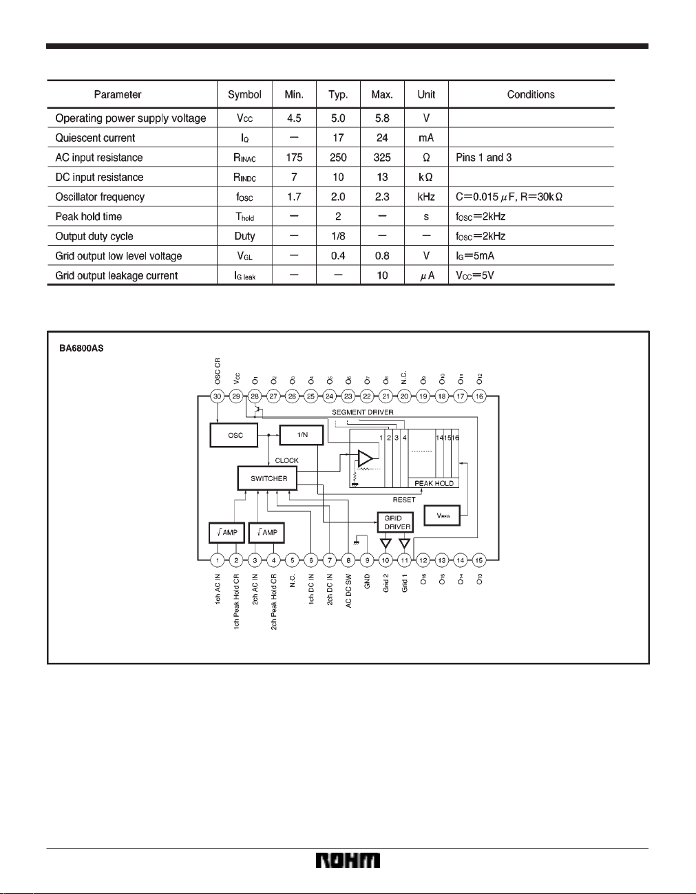
Electrical characteristics (unless otherwise noted, Ta = 25C)
Block diagram
798
Page 3
Audio ICs BA6800AS
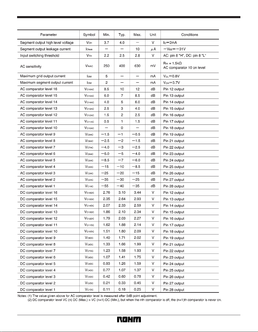
Electrical characteristics (unless otherwise noted, Ta = 25C)
799
Page 4

Audio ICs BA6800AS
Measurement circuit
Application example
800
Page 5

Audio ICs BA6800AS
Circuit operation
(1) Input block
The AC input pins are pins 1 and 3, and the DC input pins
are pins 6 and 7. Pin 8 is used to switch between the AC
and DC inputs. When the input to pin 8 is “H”, AC input
is selected (pins 1 and 3). Therefore, by using pin 8 to
switch between the AC and DC modes, the IC can do two
jobs. For example, pins 1 and 3 can be used for audio signal input, and pins 6 and 7 can be used as the input for
the signal meter output from a tuner (DC). The AC input
impedance of pins 1 and 3 is a low 250Ω (typ.), so connect potentiometers (VR
1 and VR2) in series with the in-
puts to adjust the sensitivity and ch1 and ch2 balance.
(2) Peak hold circuit
The BA6800AS features a peak hold circuit that temporarily holds peak signal levels in AC input mode. The
peak hold function can be used with the upper 12 points
(5 to 16). The peak hold time depends on the oscillator
frequency . It is 2 sec. (typ.) for an oscillator frequency of
2kHz. DC mode does not have a peak hold function.
(3) Grid output
The pin 10 and 11 grid outputs are open-collector NPN
transistors. The logic is active low (the fluorescent tube
lights when the output is “L”), so connect two PNP transistors Q1 and Q2 as shown in the application example
circuit to drive the fluorescent tubes (see Fig. 3).
(4) Segment output block
Pins 12 to 28 are the segment outputs. The output circuits are open-collector PNP transistors. When grid 1 is
“L”, the ch1 level is output (pin 1 or 6), and when grid 2
is “L”, the ch2 level is output (pin 3 or 7). Refer to Fig. 4.
(5) Grid and segment output timing chart
The grid and segment output timing is shown in Fig. 5.
(6) Attack and release times
The response characteristic for AC input signals is set by
resistor R1 and capacitor C
capacitor C
3 = 22µF , the attack time is about 4ms, and the release
C
4 for ch2 (pins 2 and 4). When R1 = 47kΩ and
3 for ch1 and resistor R2 and
time is about 1sec. (same for ch2).
Attack time : Time for the voltage on pins 2 and 4
to rise from 1V to 2.5V when the input
goes from no input to 2.6Vrms, then
back to no input.
Release time : Time for the voltage on pins 2 and 4
to fall from 2.5V to 1V when the input
goes from 2.6Vrms to no input.
(7) Oscillator frequency
The resistor R
26 and capacitor C5 connected to pin 30 de-
termine the oscillator frequency . The oscillator frequency
osc) and grid output period (T) are related as follows :
(f
T (ms) = 16 / f
osc (kHz)
801
Page 6

Audio ICs BA6800AS
Timing chart
(when oscillator frequency is 2kHz)
Attached components (refer to “Circuit operation”)
1 and C2 : input coupling capacitors.
C
VR
1 and VR2 : AC sensitivity adjustment and balance ad-
justment (3kΩ recommended).
3, R1, C4 and R2 : set the response characteristics with
C
respect to the AC input signal. In the example given, the
attack time is about 4mS and the release time is about
1sec.
R
3 : Pullup resistor for the input switching terminal (pin 8).
6 and R7 : resistor for the grid leak current path (IGleak).
R
Set so that I
4 and R5 : base bias resistors for Q1 and Q2.
R
Conditions for base bias current (I
F = 0.6V :
V
Gleak R6 (R7) < 0.6V.
R4
R
5*0.6
<
6
0.6
B) flow are VCC = 5V and
= 7.3
the base current is given by the following formula.
Operation notes
(1) Adjust the potentiometers VR
1 and VR2 (connected
to pins 1 and 3) to adjust the 0dB input level and the dispersion of ch1 and ch2.
(2) The temperature characteristic for the lighting limit
for the 16th LED is shown in Fig. 6.
IB (mA)
Set resistors R
I
B >
Q
1 and Q2 : grid output inverting transistors. Use transis-
tors for which V
8 to R25 : Resistors that reverse bias the segments and
R
5*0.6
4 (kΩ)
R
4 and R6 (R5 and R7) so that
Fluorescent tube grid current
CEO > VCC ) VEE.
0.6
*
R
6 (kΩ)
FE
h
grid when the fluorescent tube is not lit.
The application example given is for general cases. Select the resistors to suit the characteristics of the fluorescent tube used.
C
5 and R26 : set the oscillator frequency.
Capacitor C
5 should be a component with good tempera-
ture characteristics.
(3) The external resistor R
26 connected to the oscillator
(pin 30) should be in the range of 20kΩ and 100kΩ. If it
is outside this range, oscillation may stop due to the influence of temperature (see Fig. 7).
802
Page 7

Audio ICs BA6800AS
Electrical characteristics curves
External dimensions (Units: mm)
803
 Loading...