

Page 1
Optical disc ICs
4-channel BTL driver for CD players
BA6797FP / BA6797FM
The BA6797FP and BA6797FM are 4-channel BTL power drivers for CD players and each have an internal 5V regulator
(requires attached PNP transistor). Because the input stage of each driver channel connects to an operational amplifier,
and there are both positive and negative input pins, making these ICs adaptable for a wide range of inputs and greatly
simplify filter configuration. In addition, the internal level shifting circuit reduces the number of external components.
Applications
CD players, CD-ROM drives and other optical disc devices
Features
1) 4-channel BTL driver in a HSOP 28-pin power package, ideal for application miniaturization.
2) Wide dynamic range.
3) Internal thermal shutdown circuit.
4) Internal level shifting circuit reduces the number of
external components.
5) Dual positive and negative input pins, for adaptability
for a wide range of inputs (including negative phase
input). Also simplifies filter configuration.
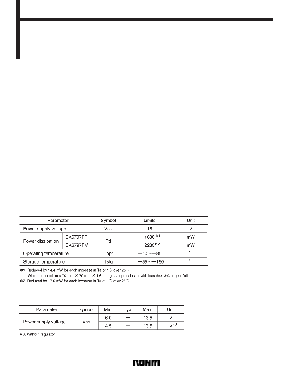
Absolute maximum ratings (Ta = 25C)
Recommended operating conditions (Ta = 25C)
364
Page 2
Optical disc ICs BA6797FP / BA6797FM
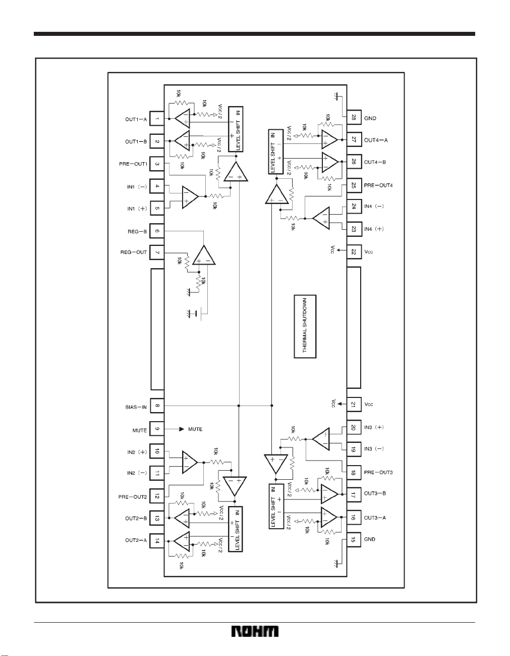
Block diagram
365
Page 3
Optical disc ICs BA6797FP / BA6797FM
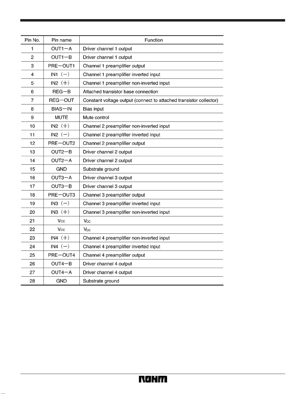
Pin descriptions
366
Page 4

Optical disc ICs BA6797FP / BA6797FM
Input / output circuits
367
Page 5

Optical disc ICs BA6797FP / BA6797FM
Electrical characteristics (unless otherwise noted, Ta = 25C, VCC = 8V, f = 1kHz, RL = 8Ω)
368
Page 6

Optical disc ICs BA6797FP / BA6797FM
Measurement circuit
369
Page 7

Optical disc ICs BA6797FP / BA6797FM
Measurement circuit switch table
370
Page 8

Optical disc ICs BA6797FP / BA6797FM
Application example
Operation notes
(1) The BA6797FP and BA6797FM have an internal
thermal shutdown circuit. Output current is muted when
the chip temperature exceeds 175C (typically).
(2) If the mute pin (pin 9) voltage is opened or lowered
below 0.5V, the output current will be muted. Pin 15
should be pulled up above 2.0V during normal use. During muting, the output pins remain at the internal bias
voltage, roughly (V
CC / 2).
(3) The bias pin (pin 8) is muted when lowered below
1.4V (typically). Make sure it stays above 1.6V during
normal use.
(4) Be sure to connect the IC to a 0.1µF bypass capacitor to the power supply, at the base of the IC.
(5) Connect the radiating fin to an external ground.
(6) The capacitor between regulator output (pin 7) and
GND also serves to prevent oscillation of the IC, so select
one with good temperature characteristics.
371
Page 9

Optical disc ICs BA6797FP / BA6797FM
Electrical characteristic curves
372
Page 10

Optical disc ICs BA6797FP / BA6797FM
External dimensions (Units: mm)
373
 Loading...