

Page 1
BA3880AS / BA3880AFS
Audio ICs
High-definition sound processor
BA3880AS / BA3880AFS
The BA3880AS and BA3880AFS are sound processor ICs that perform phase and harmonic compensation on audio
signals to accurately reproduce the "rise" section of audio signals that determines the characteristics of the sound, and
thus reproduce the original recording as naturally as possible.
Applications
!!!!
Component stereo systems, radio cassette players, car stereo systems, televisions, VCRs, and active speakers.
Features
!!!!
1) Correct distortion in the rising section of audio signals that results from miss-matched speakers and amplifiers, and
reproduces the original sound faithfully.
2) To allow application with all types of speakers and sources, the clarity can be adjusted using DC control.
3) DC control provided for selection of either processor mode or bypass mode.
4) Bass boost fixed internally to 4dB.
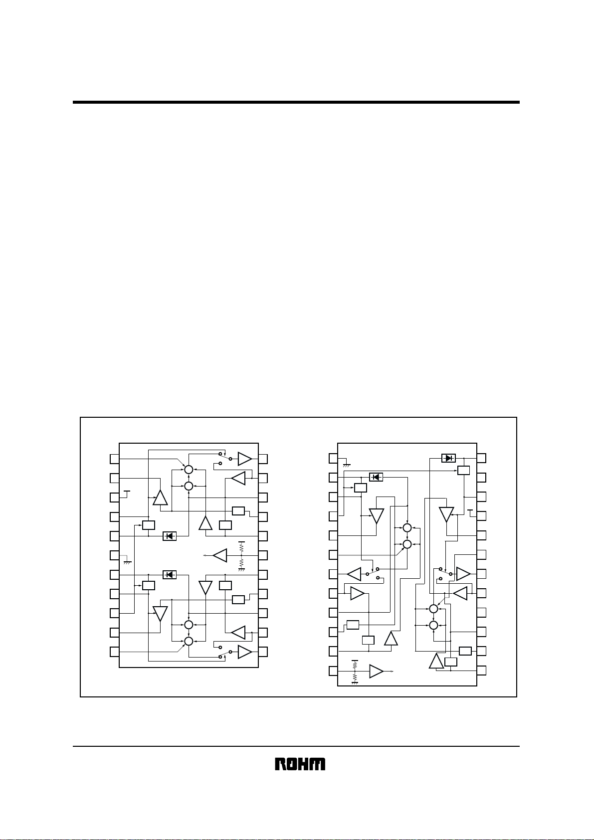
Block diagram
!!!!
BA3880AS
1
MIXL
2
VCAL
3
CC
V
4
DEFL
5
DETL
6
GND
7
DETR
8
DEFR
CTL
9
10
VCAR
11
MIXR
CTL
CTL
VCA
VCA
+
+
+
+
+
HI MID LO
+
+
+
−
−
+
+
+
HI
+
MID
+
+
+
+
BA3880AFS
CTL
HPF
24
DETL
23
22
DEFR
21
CC
V
20
VCAL
19
MIXL
18
OUTL
17
INL
16
15
APFL
14
HPFL
13
LPFL
1
22
OUTL
21
INL
20
APFL
HPF
19
LPF
LPF
HPF
LO
HPFL
18
LPFL
17
BIASC
16
LPFR
15
HPFR
APFR
14
13
INR
OUTR
12
GND
DETR
DEFR
CTL
VCAR
MIXR
OUTR
INR
APFR
HPFR
LPFR
BIASC
2
CTL
3
VCA
LO
−
+
+
+
+
+
+
+
+
HI
MID
LO
+
+
+
−
LPF
HPF
LPF
VCA
+
+
HI
MID
+
+
+
4
5
6
7
8
9
10
11
12
Page 2
Audio ICs
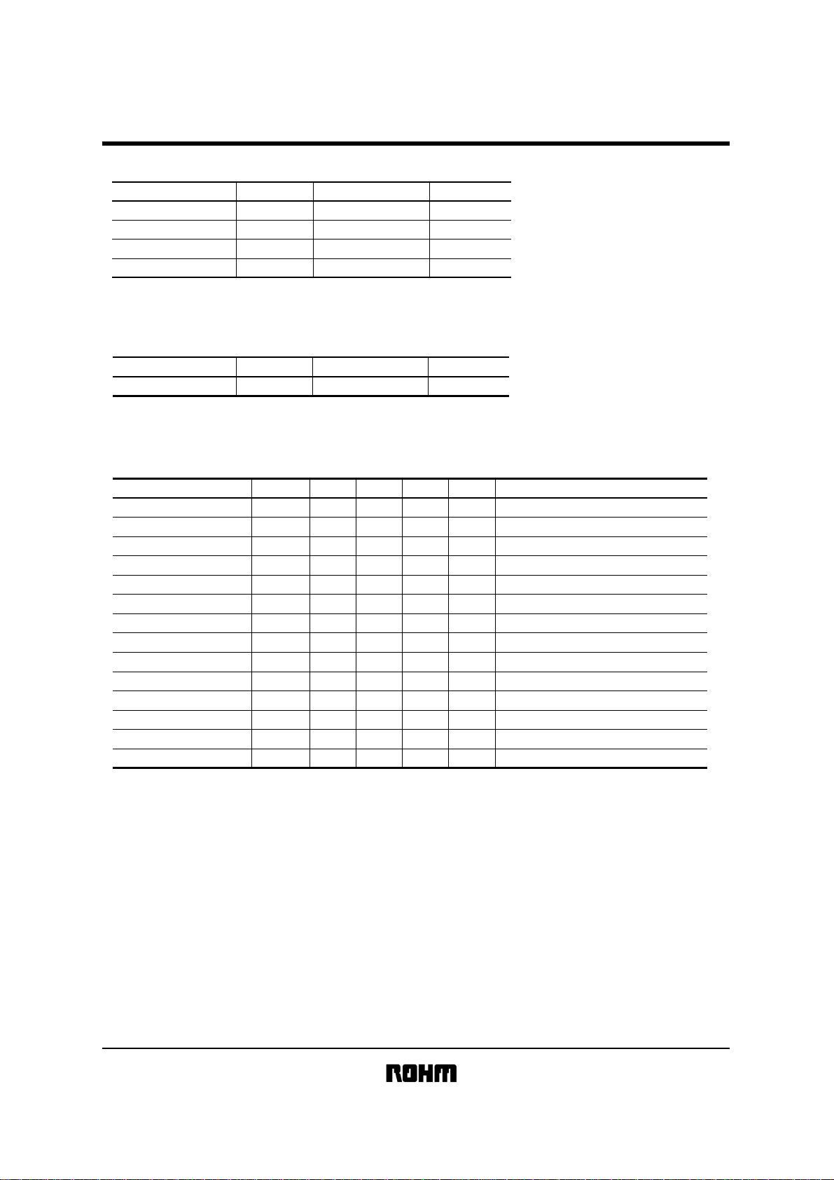
Absolute maximum ratings
!!!!
Parameter
Power supply voltage
Power dissipation
Operating temperature
Storage temperature
Reduced by 10mW for each increase in Ta of 1°C over 25°C.
∗
Recommended operating conditions
!!!!
(Ta = 25°C)
Symbol Limits Unit
CC
V
Pd
Topr
Tstg
11
∗
1000
−40~+85
−55~+125
BA3880AS / BA3880AFS
V
mW
°C
°C
Parameter
Power supply voltage V
Electrical characteristics
!!!!
(unless otherwise noted, Ta = 25°C, V
Parameter
Circuit current
Voltage gain 1
Voltage gain 2
Voltage gain 3
Voltage gain 4
Voltage gain 5
Channel balance
Maximum output voltage
Output noise voltage 1
Output noise voltage 2
Total harmonic distortion 1
Total harmonic distortion 2
Channel separation
Ripple rejection ratio
∗Note : When VCTL = 9V, the IC is in bypass mode (through operations).
When V
CTL = 4.5V, the IC is in processor mode (enhance operations) with minimum definition level.
CTL = 0V, the IC is in processor mode (enhance operations) with maximum definition level.
When V
Symbol Limits Unit
CC
Symbol
I
CC
G
V1
G
V2
G
V3
G
V4
G
V5
5.4~10.8 V
CC
= 9V, fIN = 1kHz, VIN = 200mVrms, Rg = 600Ω, RL = 100k Ω and V
Min.
3.9
Typ.
5.9
−2.0
−2.5
−1.0
9.0
−0.5
1.0
11.0
−
4.0
CB −2.0 0 2.0 dB
V
V
NO1
V
NO2
THD
THD
OM
2.0 2.3 − Vrms THD
− 210µVrms
− 16 70 µVrms
1
− 0.005 0.05 % 400Hz~30kHz BPF,
2
− 0.04 0.4 % 400Hz~30kHz BPF
CS −−67 −60 dB
RR 60 68 − dB
Max. Unit Conditions
11.8
0
2.0
1.5
4.0
13.0
−
mA
dB
dB
dB
dB
dB
IN
=
0Vrms
V
V
CTL
= 9V
fIN = 10kHz
IN
= 10kHz, V
f
IN
= 50Hz
f
fIN = 10kHz, V
=
1%
Rg = 0Ω, DIN AUDIO, V
Rg = 0Ω, DIN AUDIO
VIN = 1Vrms
Rg = 0Ω, fR = 100Hz, VR = 100mVrms
CTL
CTL
= 0V
= 0V
CTL
= 4.5V)
CTL
= 9V
V
CTL
=
9V
Page 3
Audio ICs
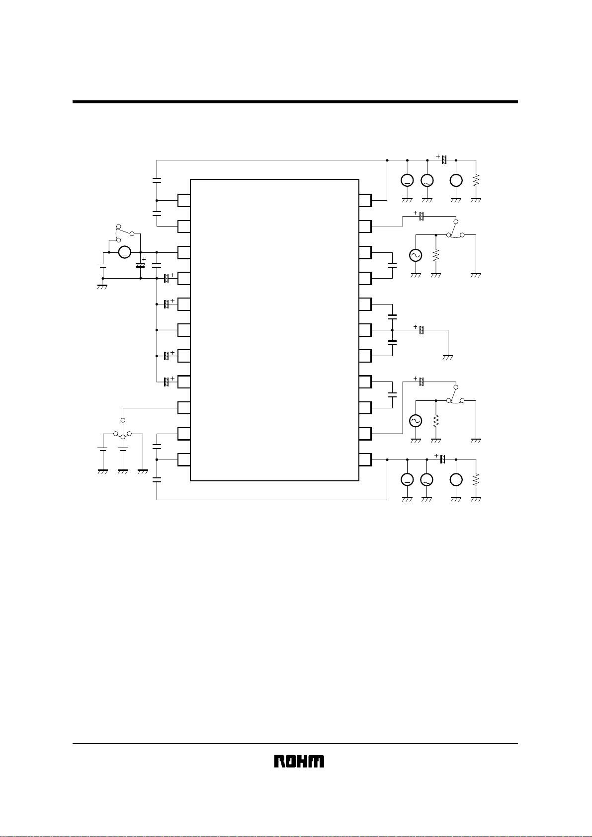
Measurement circuit
!!!!
BA3880AS
470p
6800p
BA3880AS / BA3880AFS
1 22
MIXL
2 21
VCAL
OUTL
INL
4.7µ
V
V
4.7µ
THD
100k
A
9V
9V 4.5V
47µ
3 20
CC
V
0.1µ
4 19
1µ
4.7µ
4.7µ
1µ
470p
6800p
DEFL
DETL
5 18
GND
6 17
7 16
DETR
8 15
DEFR
9 14
CTL
10 13
VCAR
11 12
MIXR
BA3880AS
Fig.1
APFL
HPFL
LPFL
BIASC
LPFR
HPFR
APFR
INR
OUTR
0.01µ
0.068µ
0.068µ
0.01µ
600
47µ
4.7µ
600
4.7µ
V
V
(Units) R : Ω
THD
C : F
100k
Page 4

Audio ICs
BA3880AFS
9V 4.5V
THD
100k
BA3880AS / BA3880AFS
1 24
GND
2 23
4.7µ
1µ
6800p
470p
4.7µ
V
V
DETR
3 22
DEFR
4 21
CTL
VCAR
5 20
6 19
MIXR
OUTR
7 18
INR
8 17
BA3880AFS
DETL
DEFL
V
VCAL
MIXL
OUTL
INL
4.7µ
1µ
0.1µ
CC
6800p
470p
47µ
9V
A
4.7µ
V
V
THD
100k
600
4.7µ
47µ
APFR
9 16
0.01µ
HPFR
10 15
LPFR
11 14
0.068µ
12
BIASC
Fig.2
APFL
HPFL
LPFL
600
0.01µ
13
0.068µ
(Units) R : Ω
C : F
Page 5

BA3880AS / BA3880AFS
Audio ICs
Circuit operation
!!!!
The BA3880AS and BA3880AFS high-definition sound processor system ICs treat the amplifiers and speakers as a total
audio systems, and perform signal processing at the amplifier input stage to accurately reproduce the rise sections of
audio signals that determine the characteristics of sound, and ensure that the replayed audio is as close to the original
sound and as natural sounding as possible.
Problems relating to playback of sound on audio systems.
With naturally-generated sound, high-frequency harmonic components generally occur first, followed by the fundamental
frequency components. This also applies to the attack section of the sound that characterizes many musical instruments.
It is the amplitude component that gives form to the frequency component and envelope at the rising point of sound, and
this expresses the characteristics of the sound. Therefore, when replaying audio on audio playback systems, it is
extremely important that the rise section of the signal be expressed accurately with respect to the original sound.
However, there is inevitable mismatching between the speakers and amplifiers in current audio systems. Solid-state
power amplifiers use negative feedback techniques and operate off a fixed voltage supply, but as speakers are a current
element, mismatching in the system inevitably occurs. In addition, the speaker impedance characteristics are strongly
influenced by the electrical reactance of the voice coil, and the mechanical reactance of the cone assembly. As a result of
this, distortion is generated in the rising sections of audio signals, causing phase shift in the reproduced sound. In addition,
impedance increases in the treble region which reduces the speaker amplitude and reduces the harmonic component,
and as a result there is a tendency to masking of large mid-frequency signal components that follow, and this makes it
difficult to reproduce the rising sections of the sound.
Operating principle
!!!!
To solve the problems described above, the BA3880AS and BA3880AFS perform the audio signal processing described
below.
Phase shift compensation
BASS MIDDLE TREBLE
20 150 2.4k 20k f (Hz)
The input signal is separated into three regions: bass (20Hz to 150Hz), middle (150Hz to 2.4kHz) and treble (2.4kHz to
20kHz). These regions are then joined again with the middle and treble regions phase shifted −180° and −360
respectively with respect to the bass signal. This phase shift adjusts the delay time characteristic for each band and
minimizes the distortion of the rising section of the audio signal.
Amplitude compensation (harmonic compensation)
To maintain appropriate auditory balance for the treble region that is made up of harmonic components, a high-speed
detector and high-performance VCA circuit are used for amplitude control of the treble component. The amount of
compensation is determined from a calculation performed based on the DC level input to the CTL pin, and the DC level
detected from the input signal. The internal control signal obtained from this calculation compensates the amplitude of the
treble component input to the VCA. This amplitude compensation recovers the harmonic component, and improves the
reproduction clarity (definition level) of instruments and vocals.
°
Page 6

BA3880AS / BA3880AFS
Audio ICs
Bass boost
To maintain good balance with the dynamically changing treble component, the bass component is boosted. The bass
boost is fixed at 4dB (typ.) internally, and cannot be adjusted.
Mode switch
The DC voltage on the CTL pin can be used to switch the IC between processing mode and bypass mode. When
processing mode is selected, the audio signal is enhanced using the compensation circuits described above before being
output. When bypass mode is selected, the signal bypasses all of the compensation circuits, and only passes through a
buffer amplifier before output.
External components
The frequency characteristic in processing mode with maximum definition level is given below.
GAIN
C1
C2
C1: External capacitor
connected between the
VCA and MIX pins
(6800pF in the
application circuit).
C2: External capacitor
connected between the
OUT and MIX pins
BASS BOOST
LARGE
SMALL
LARGE SMALL
DEFINITION LEVEL
(470pF in the application
circuit).
FREQUENCY
As indicated in the diagram, capacitors C1 and C2 determine the treble component cutoff frequency. By varying the
values of these components, the frequency characteristic can be changed as indicated by the dotted line in the diagram.
This varies the balance of the harmonic component, and is an important factor in determining the tone quality.
Control table
Item Threshold level Mode setting Definition level
V
CC
0.64 ×
V
CC
V
CTL
0.57 ×
V
CC
0V (GND)
Recommended setting range for bypass mode
0.75 ×
V
CC
0.5 ×
V
CC
Recommended setting range for processor mode
Min. (1dB Typ.)
Max. (11dB Typ.)
Page 7

Audio ICs
Application example
!!!!
BA3880AS
BA3880AS / BA3880AFS
V
CC
GND
V
CTL
47µ
470p
68000p
68000p
470p
0.1µ
1µ
4.7µ
4.7µ
1µ
MIXL
VCAL
V
DEFL
DETL
GND
DETR
DEFR
CTL
VCAR
10
MIXR
11
0.01µ
0.068µ
0.068µ
0.01µ
4.7µ
4.7µ
4.7µ
4.7µ
L−ch
OUTPUT
L−ch
INPUT
47µ
R−ch
INPUT
R−ch
OUTPUT
OUTL
1
2
CC
3
4
5
6
7
8
9
VCA
CTL
CTL
VCA
+
+
+
+
+
HI MID LO
+
+
+
−
−
+
+
+
HI MID LO
+
+
+
+
+
HPF
LPF
LPF
HPF
22
INL
21
APFL
20
HPFL
19
LPFL
18
BIASC
17
LPFR
16
HPFR
15
APFR
14
INR
13
OUTR
12
Fig.3
(Units) R : Ω
C : F
Page 8

Audio ICs
BA3880AFS
BA3880AS / BA3880AFS
V
CTL
R−ch
OUTPUT
R−ch
INPUT
0.068µ
0.01µ
47µ
6800p
470p
4.7µ
4.7µ
4.7µ
1µ
GND
DETR
DEFR
CTL
VCAR
MIXR
OUTR
INR
APFR
HPFR
10
LPFR
11
BIASC
12
DETL
1
24
4.7µ
CTL
2
CTL
3
4
5
6
VCA
LO
−
+
+
+
HI
MID
+
+
+
+
+
VCA
7
8
+
+
+
+
9
HPF
+
HI
MID
LO
+
+
+
−
23
DEFR
22
V
CC
21
VCAL
20
MIXL
19
OUTL
18
INL
17
16
APFL
1µ
0.1µ
6800p
470p
4.7µ
4.7µ
GND
47µ
V
L−ch
OUTPUT
L−ch
INPUT
CC
15
LPF
LPF
HPF
HPFL
14
LPFL
0.01µ
13
0.068µ
Fig.4
(Units) R : Ω
C : F
Page 9

BA3880AS / BA3880AFS
Audio ICs
Operation notes
!!!!
(1) Control pin (CTL)
The level of the DC voltage applied to the control pin should be in the range 0V to V
possible in the region of the threshold voltage. Allow sufficient margin when setting this voltage.
(2) Recommended operating range
Provided the IC is operated within the operating temperature range and within the recommended operating conditions,
the general circuit functions are guaranteed to operate correctly, and there will not be significant changes in the electrical
characteristics.
(3) Application example
Provided the circuit constants in the application example circuit are used, the application circuit should function correctly.
However, we recommend that you confirm the characteristics of the circuit in actual use, and take note of the cautionary
items described above. If you change the circuit constants, check both the static and transient characteristics of the circuit,
and allow sufficient margin to accommodate variations in both the IC and the external components.
(4) License
The ICs are manufactured under license from BBB Sound Inc. (U.S.A.). A license agreement with BBB Sound Inc. is
required to use this component.
Electrical characteristic curves
!!!!
(dB)
DEFINITION LEVEL :
12
10
8
6
4
2
VCC =
=
f
VIN =
9V
10kHz
200mVrms
(dB)
DEFINITION LEVEL :
16
14
12
10
8
6
4
2
V
CC
= 9V
f = 10kHz
CTL
= 0V
V
CC
. Appropriate switching may not be
0 0.5 1.0 1.5 2.0 2.5 3.0 3.5 4.0 4.5
CONTROL VOLTAGE : V
Fig. 3 Definition level vs.
control voltage
External dimensions
!!!!
BA3880AS
19.4±0.3
0.3
±
3.95
0.2
±
3.4
22
1
0.51Min.
1.778
12
11
0.5±0.1
CTL
(V)
(Units : mm)
6.5±0.3
7.62
0°~15°
0.1
±
0.3
−10 −20 −30 −40 −50 −60
0
INPUT VOL TAGE : VIN
Fig. 4 Definition level vs.
input voltage
BA3880AFS
10.0±0.2
24
±0.2
7.8±0.3
5.4
1
±0.1
1.8
0.8
0.11
(dBV)
13
0.36±0.1
SSOP-A24SDIP22
−70 −80
12
0.15±0.1
0.3Min.
0.15
 Loading...