

Page 1
Audio ICs
Preset equalizer sound control
(P.S.C) IC
BA3842F
The BA3842F is a preset graphic equalizer IC with dynamic bass boost which is designed for audio equipment.
Applications
Mini-component stereos
Micro-component stereos
Radio cassette recorders with CD
Features
1) Includes preset equalizer function with five equalizer
positions and a flat mode setting.
2) Built-in dynamic bass boost with gain settings from 0
to 20dB in steps of 5dB.
3) Low distortion and low noise.
4) Built-in dynamic bass boost and interlocked ALC
(Auto Level Control).
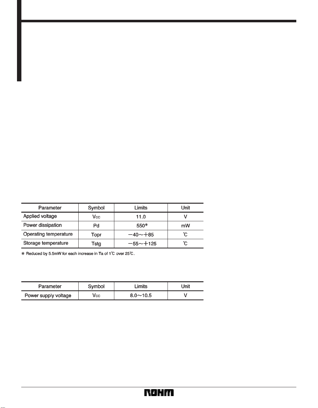
Absolute maximum ratings (Ta = 25C)
Recommended operating conditions
563
Page 2

Audio ICs BA3842F
Block diagram
564
Page 3
Audio ICs BA3842F
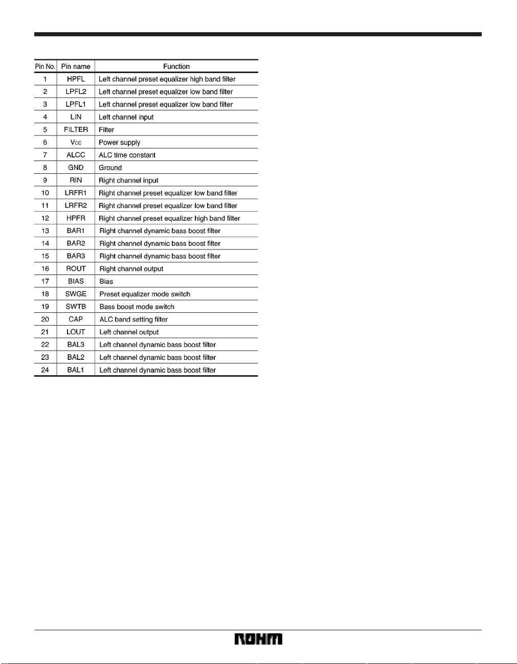
Pin descriptions
565
Page 4
Audio ICs BA3842F
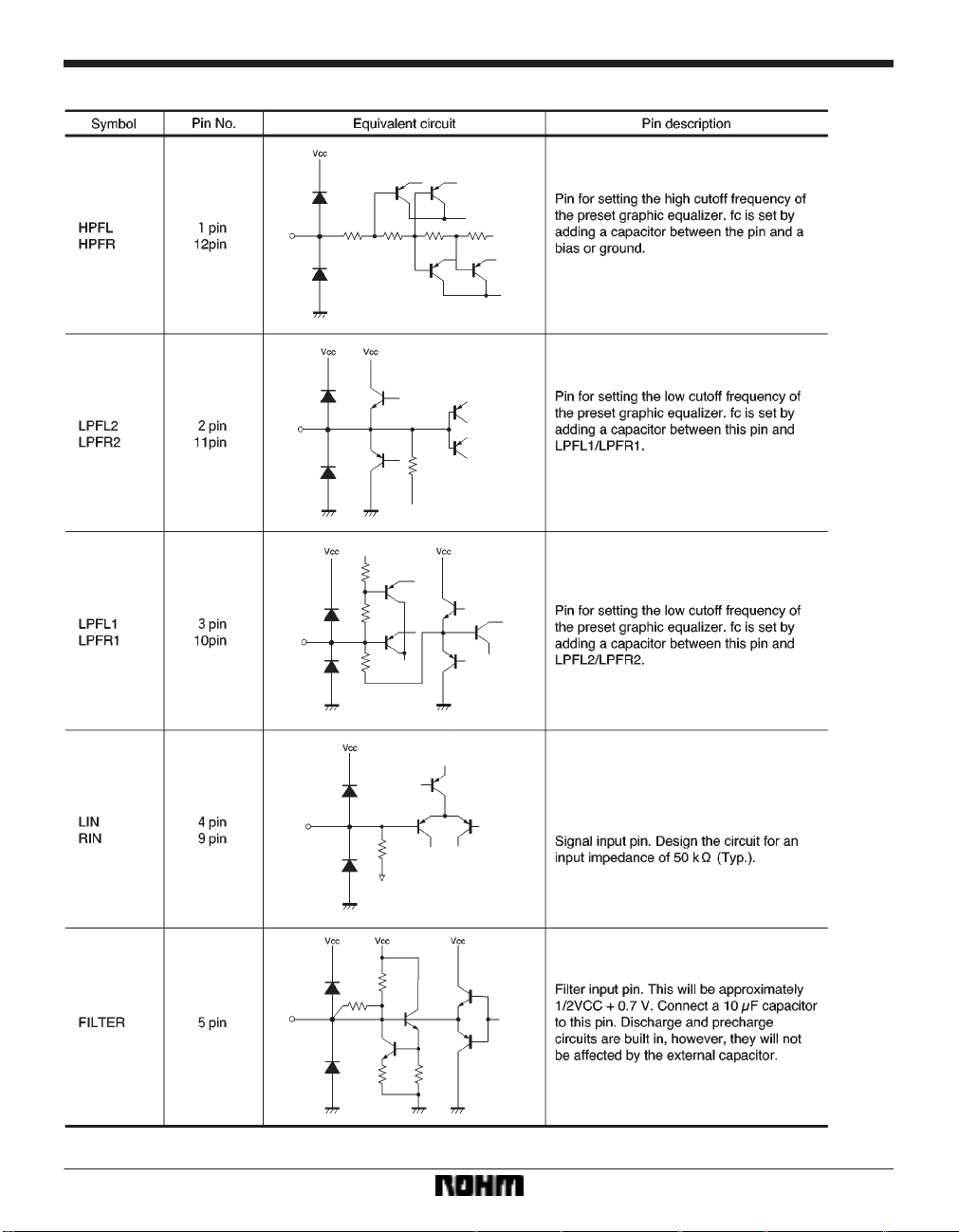
Input / output circuits
566
Page 5

Audio ICs BA3842F
567
Page 6

Audio ICs BA3842F
568
Page 7

Audio ICs BA3842F
Electrical characteristics (unless otherwise noted, Ta = 25C, VCC = 10V, f = 1HZ, VIN = 200mVrms,
preset equalizer normal : R
g = 620Ω, during dynamic bass boost : RL = 10kΩ)
Operating specifications
Input and output signal pins are in phase.
569
Page 8

Audio ICs BA3842F
Reference values for application circuit example (unless otherwise noted, Ta = 25C, VCC = 10V,
V
IN = 200mVrms, preset equalizer normal : Rg = 620Ω, during dynamic bass boost : RL= 10kΩ)
Operating specifications
Input and output signal pins are in phase.
570
Page 9

Audio ICs BA3842F
Measurement circuit
571
Page 10

Audio ICs BA3842F
Circuit operation
(1) Operating power supply voltage range
Within the operating power supply voltage range, circuit
functioning is guaranteed as long as the operating temperature range is not exceeded. However, verify carefully
that the voltage, temperature, and component values are
appropriate.
(2) Control pins and control voltage settings
(1) The DC control range is 0 V to V
CC for the preset
equalizer and the dynamic bass boost control pins (pins
18 and 19). Make sure that the voltage applied to these
control pins does not exceed V
CC.
(2) Mode switch threshold values are determined by di-
viding resistors between V
CC and GND of both the preset
equalizer and bass boost. If the control voltages are divided from the supply voltage of the IC, they will have
greater tolerance with respect to V
CC fluctuations.
(3) During mode switching, an abrupt change in the level
of the DC output may occur, causing a sound. In this
case, add the capacitor and resistor indicated in the application, or only the capacitor as needed.
4) Here is an example of determining the control pin
voltage setting with the input of three values.
(3) Input coupling capacitors
Note that the polarity of the input coupling capacitors will
change depending on the DC voltage to which they are
connected. Set capacitors based on the frequency band
to be used, taking into consideration the fact that the input impedance is 50kΩ.
(4) Load resistances
If the values of the load resistors are too small, the output
gain and total harmonic distortion may fluctuate slightly .
T ake this into consideration when connecting the subsequent stage.
(5) The dynamic bass boost filter is a multi feedback
active filter which forms the B.P.F.
F
O = 1 / [2π{(R1 //R2)R3C1C2}
f
Q = 1 / 2{(R
HO = R3 /{R1(1C1 /C2)
When R
0.22µF,
f
O 61Hz Q 3.8 HO 19
OUT C B A
0 V L L L
1.3 V L L H
3 V L H L
5 V L H H
7 V H L L
9 V H L H
O can be changed with the C value.
3 /(R1 //R2)}
1 = 2.4kΩ, R2 = 4.3kΩ, R3 = 91kΩ, and C1 = C2 =
1/2
1/2
}
1/2
L : 0V
H : V
]
CC
Connect OUT to the control pin.
Regarding the values of the various constants, it is important to consider current dissipation and other such problems. If such a problem should occur, change the
constants and redesign the diode logic.
572
If R
1 and R2 are too small, the bass boost characteristics
such as boost gain and crosstalk may change. Keep this
in mind when setting filter values. Furthermore, design
the application so that the bass boost level increments by
5dB from 5 to 20dB when H
O = 19.
Page 11

Audio ICs BA3842F
(6) Filter for preset equalizer
(1) Low band
The low cutoff frequency fc of each mode is given by the
following equation :
fc = 1 / 2πCR = 1 / (2π C 15.6kΩ)
When C = 0.22µF,
fc
46 (Hz)
The fc value can be changed to make slight changes in
the boost and cutoff gain of each mode.
(2) High band
The high cutoff frequencies fc of each mode are given by
the following equation :
fc = 1 / 2πCR
When C = 2200pF,
ROCK : R = 8.0kΩ fc
JAZZ : R = 10.7kΩ fc
CLASSIC : R = 14.9kΩ fc
BGM. POP : R = 17.4kΩ fc
9.0 (kHz)
6.8 (kHz)
4.8 (kHz)
4.2 (kHz)
The fc values can be changed to make slight changes in
the boost and cutoff gain of each mode.
Note:
If a high or low fc value is changed, the gains of all modes
will change. The gain cannot be changed for only one
mode.
(7) ALC
The band of ALC detection can be changed with the value of C
4. It must be adjusted appropriately for the dynam-
ic bass boost f
0.1µF, thus fc = 1 / 2πC
O. In the example application circuit C4 =
4 (R5 //R6 //R7)
160 (Hz)
The detection wave is dually rectified. In the example application circuit, it is 1.3V
rms, but if the resistors R8 and R9
are connected as shown below, it will lower the ALC level.
Adjust the ALC level as needed. The detection band at
this time is :
fc = 1 / 2πC
4 (R5 //R6 //R7 //R8 ///R9)
(8) Attack time and release time
Adjust the attack and release times with the resistors and
capacitors connected to the ALCC pin. The attack time
is determined by R
is determined by R
10 (1kΩ) and C5, and the release time
11 and C5. If the value set for C5 is below
4.7µF, the ALC level may become unstable.
573
Page 12

Audio ICs BA3842F
Electrical characteristic curves (reference values)
574
Page 13

Audio ICs BA3842F
External dimensions (Units: mm)
575
 Loading...