

Page 1
Alpha Industries, Inc. [781] 935-5150 • Fax [617] 824-4579 • Email sales@alphaind.com • www.alphaind.com 1
Specifications subject to change without notice. 5/00A
25–31 GHz Surface Mount Amplifier
Features
■ Surface Mount Package
■ 13 dB Gain
■ +16 dBm Output Power
■ Single Voltage Operation
■ 100% RF and DC Testing
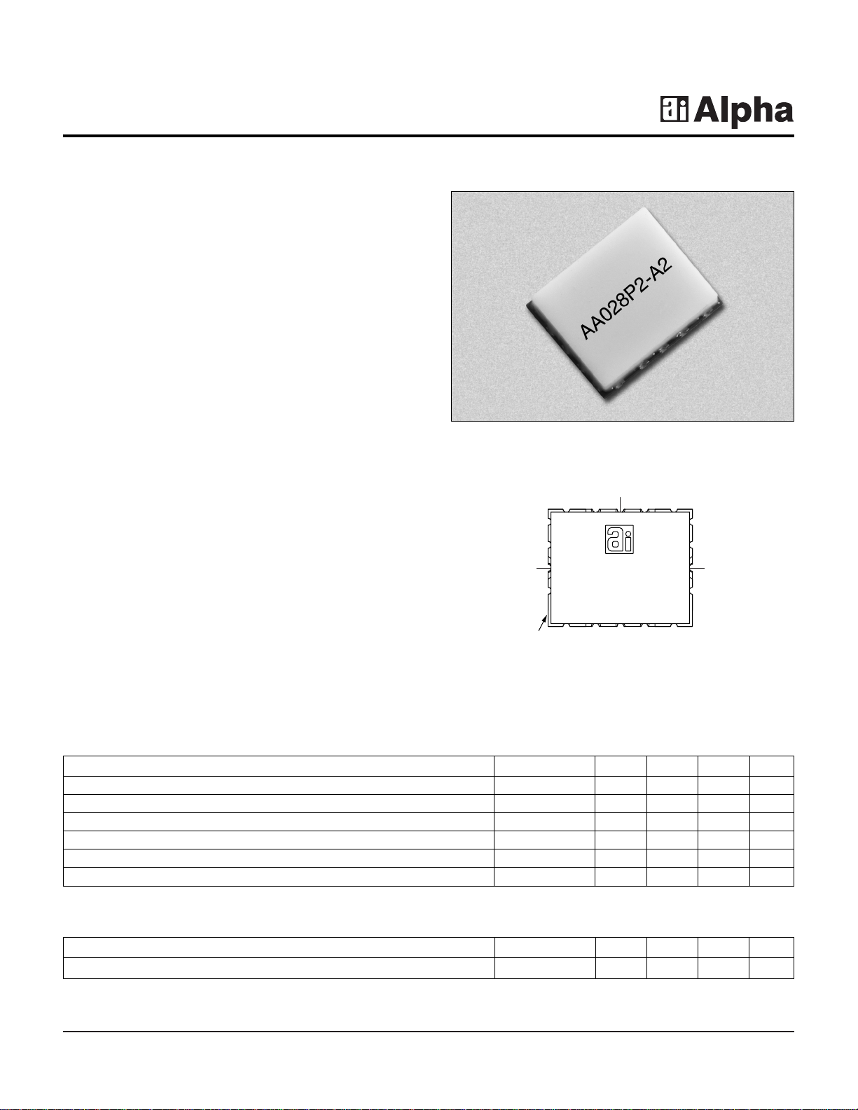
AA028P2-A2
Patent Pending
Description
The AA028P2-A2 is a broadband millimeterwave driver
amplifier in a rugged surface mount package which is
compatible with high volume solder installation. The
amplifier is designed for use in millimeterwave
communication and sensor systems as a gain stage in the
receiver, transmitter, or LO chain when high gain and
linearity are required.The robust cer amic surf ace mount
package provides excellent electrical perf ormance and a
high degree of environmental protection for long-term
reliability. A single supply voltage simplifies bias
requirements.All amplifiers are screened at the operating
frequencies prior to shipment for guaranteed
performance. Amplifier is targeted for high volume
millimeterwave applications such as point-to-point and
point-to-multipoint wireless communications systems.
Parameter Symbol Min. Typ. Max. Unit
Bandwidth BW 25 24–32 31 GHz
Small Signal Gain G1113 dB
Input Return Loss RL
I
7dB
Output Return Loss RL
O
9dB
Output Power at 1 dB Gain Compression P
1 dB
14 16 dBm
Temperature Coefficient of Gain dG/dT -0.025 dB/C
Electrical Specifications at 25°C (VD= 5.5 V)
Parameter Symbol Min. Typ. Max. Unit
Drain Current I
D
70 110 mA
DC
RF
Pin Out
AA028P2-A2
YYWW
RF In RF Out
Orientation
Indicated by
Missing
Castellations
V
D
Page 2
25–31 GHz Surface Mount Amplifier AA028P2-A2
2 Alpha Industries, Inc. [781] 935-5150 • Fax [617] 824-4579 • Email sales@alphaind.com • www.alphaind.com
Specifications subject to change without notice. 5/00A
Characteristic Value
Operating Temperature (TC) -55°C to +90°C
Storage Temperature (TST) -65°C to +150°C
Bias Voltage (VD1)7 V
DC
Power In (PIN) 13 dBm
Absolute Maximum Ratings
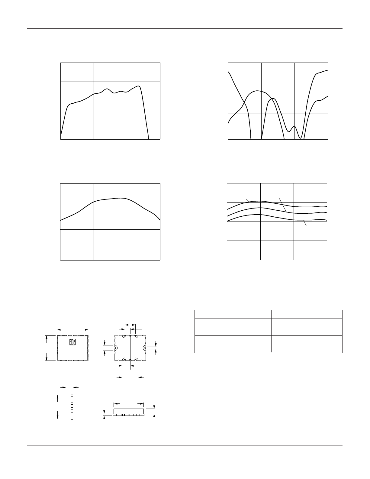
Frequency (GHz)
Gain vs. Frequency
Gain (dB)
0
5
10
15
20
20 25 30 35
Frequency (GHz)
Output Power vs. Frequency
P
1 dB
(dBm)
10
12
14
16
18
20
25 27 29 31
-15
-10
-5
0
20 25 30 35
S
22
S
11
Frequency (GHz)
Return Loss vs. Frequency
Return Loss (dB)
Frequency (GHz)
Gain vs. Frequency
Gain (dB)
0
5
10
15
20
25 27 29 31
+85˚C
-55˚C
+25˚C
Typical Performance Data (VD= 5.5 V)
Outline
0.241
(6.12 mm)
0.040
(1.02 mm)
0.016
(0.41 mm)
0.194
(4.93 mm)
0.056
(1.42 mm)
0.204
(5.18 mm)
0.251
(6.38 mm)
2X 0.044
(1.12 mm)
8X 0.020
(0.51 mm)
2X 0.129
(3.28 mm)
C
L
2X 0.064
(1.63 mm)
2X 0.043
(1.09 mm)
2X 0.085
(2.16 mm)
C
L
Page 3

25–31 GHz Surface Mount Amplifier AA028P2-A2
Alpha Industries, Inc. [781] 935-5150 • Fax [617] 824-4579 • Email sales@alphaind.com • www.alphaind.com 3
Specifications subject to change without notice. 5/00A
Typical S-Parameters at 25°C (VD= 5.5 V)
Frequency
S
11
S
21
S
12
S
22
(GHz) Mag. (dB) Ang. (Deg.) Mag. (dB) Ang. (Deg.) Mag. (dB) Ang. (Deg.) Mag. (dB) Ang. (Deg.)
1 -1.8891 -125.3600 -43.2540 164.3700 -58.670 -88.492 -1.12620 -126.7000
3 -2.4345 175.9900 -35.7840 90.2530 -53.792 -88.848 -3.10970 154.1000
5 -2.8771 99.7540 -29.3650 -42.4260 -66.955 60.394 -3.45190 -165.7400
7 -3.2392 27.9020 -25.1380 -138.9600 -45.067 -77.408 -5.02160 128.2200
9 -3.5435 -34.6070 -45.0210 28.5080 -46.099 -69.574 0.11855 55.1550
11 -3.7858 -83.1640 -44.3000 -80.0050 -41.912 -87.216 -0.33998 -9.6574
13 -4.0416 -122.2800 -42.2600 -73.9500 -46.329 -78.549 -1.22410 -58.8080
15 -4.6036 -159.9000 -32.2730 -110.7900 -43.375 -51.890 -1.80850 -96.3240
17 -6.7582 150.4900 -18.7250 171.5900 -42.826 -60.249 -1.97470 -127.2700
18 -10.4750 109.0100 -11.1660 129.3600 -41.750 -24.941 -1.96860 -142.4000
19 -16.9020 18.9510 -4.4860 77.5880 -37.305 -29.700 -1.81710 -158.8000
20 -11.8620 -131.0900 0.8482 44.5160 -40.473 -57.605 -1.78800 84.9140
21 -10.0930 142.7400 8.3172 -45.1180 -36.456 -119.280 -4.31700 38.4980
22 -8.7935 97.3620 9.4482 -120.5400 -35.487 165.880 -6.84150 3.4238
23 -6.4440 48.8610 9.9504 178.0300 -35.753 105.470 -9.76340 -40.7050
24 -5.5792 -1.6998 10.7623 121.8400 -35.559 42.297 -19.81200 -92.3350
25 -5.6318 -51.0240 11.7960 66.6550 -35.363 -19.760 -14.91000 27.3380
26 -6.2769 -100.3300 12.1690 4.0189 -34.294 -71.223 -7.86290 -34.2280
27 -8.1182 -152.0100 13.1640 -52.5350 -33.817 -128.310 -7.12030 -95.0830
28 -12.4100 161.5400 12.0730 -115.5400 -32.020 178.760 -10.03700 -142.3600
29 -17.1150 147.2600 12.4960 -170.9200 -31.971 121.260 -13.45400 -158.0600
30 -15.6470 120.7500 12.3430 128.7300 -32.153 69.648 -12.44600 -174.4100
31 -16.9560 37.1260 13.3830 62.0720 -30.995 12.728 -14.62300 156.8700
32 -10.9470 -164.3900 13.4400 -40.9440 -30.749 -79.782 -7.19450 -176.2900
33 -7.8258 88.1560 3.2386 -136.7100 -38.601 -171.040 -2.69680 111.5000
34 -7.3537 28.4740 -7.9820 168.9300 -41.455 151.590 -1.89540 56.9890
35 -6.5525 -19.3420 -15.7300 129.1800 -38.996 95.603 -1.47920 6.1703
36 -5.6230 -65.3560 -25.1300 97.3710 -38.487 56.350 -1.16540 -44.0600
38 -3.7803 -160.9200 -31.5360 4.8599 -33.430 -18.492 -0.98473 -148.8900
40 -2.2359 96.8240 -25.9250 -110.9000 -28.181 -125.890 -1.47240 101.8500
Page 4

25–31 GHz Surface Mount Amplifier AA028P2-A2
4 Alpha Industries, Inc. [781] 935-5150 • Fax [617] 824-4579 • Email sales@alphaind.com • www.alphaind.com
Specifications subject to change without notice. 5/00A
“Alpha Two” Surface Mount Package
Handling and Mounting
Millimeterwave components require careful mounting
design to maintain optimal performance.The Alpha Two
surface mount package (patent pending) provides a
rugged and repeatable electrical connection using
standard solder techniques.
Handling
The Alpha Two surface mount package is very rugged.
However, due to ceramic’s brittle nature, one should
exercise care when handling with metal tools .Do not apply
heavy pressure to the lid.Vacuum tools may be used to
pick and place this part.
Only personnel trained in both ESD precautions and
handling precautions should be allowed to handle these
packages.
Package Construction
The Alpha Two surface mount package consists of a base
and a lid.The package base is ceramic with filled vias and
plated castellations.The package lid is unplated alumina.
The lid seal is epoxy.
Mounting Design
The Alpha Two surface mount package is installed on top
of a printed circuit board on a specially designed footprint.
Mounting footprint geometry will be supplied by Alpha
Industries in electronic formats or paper drawing.
Mounting the Package
The Alpha Two surface mount package is compatible with
high-volume surface mount installation using solder.RF
and DC connections are accomplished with metallized
edge castellations that hold solder fillets. Ground
connections are accomplished by both metallized edge
castellations and filled vias to the bottom of the package.
Care should be taken to ensure that there are no voids
or gaps in the solder so that a good RF, DC, and ground
contact is maintained.
Alpha Two Surface Mount Package Installation
Printed Ccircuit Board
Rogers 4003
0.008" (0.20 mm) Thick
Electrically & Thermally
Conductive Ground Plane
RF In
RF Out
DC Lines
Solder Fillets
Footprint Geometry for Alpha Two
Surface Mount Package
RF In RF Out
DC Connections
DC Connections
64 Via Holes
 Loading...