

Page 1

INTEGRATED CIRCUITS
74HC/HCT9323A
Programmable ripple counter with
oscillator (3-State)
Objective specification 1995 Oct 27
IC06 Data Handbook
Page 2
Philips Semiconductors Objective specification
Programmable ripple counter with oscillator
(3-State)
FEATURES
•8-pin space saving package
•Programmable 3-stage ripple counter
•Suitable for over-tone crystal application up to 85MHz
(V
= 5V10%)
CC
•3-State output buffer
•Two internal capacitors
•Recommended operating range for use with third overtone
crystals 3V to 6V
•Oscillator stop function (MR)
•Output capability:
bus driver (15 LSTTL)
•I
category: MSI
CC
APPLICATIONS
•Control counters
•Timers
•Frequency dividers
•Time-delay circuits
•CIO (Compact Integrated Oscillator)
•Third-overtone crystal operation
DESCRIPTION
The 74HC/HCT9323A are high-speed Si-gate CMOS devices. They
are specified in compliance with JEDEC standard no. 7A.
The HC/HCT 9323A are oscillators designed for quartz crystal
combined with a programmable 3-State counter, a 3-State output
buffer and an overriding asynchronous master reset (MR
two select inputs S1 and S2 the counter can be switched in the
divide-1, 2, 4 or 8 mode. If left floating the clock is divided by 8. The
oscillator is designed to operate either in the fundamental or third
overtone mode depending on the crystal and external components
applied. On-chip capacitors minimize external component count for
third overtone crystal applications.
The oscillator may be replaced by an external clock signal at input
X1. In this event the other oscillator pin (X2) must be floating. The
counter advances on the negative-going transition of X1. A LOW
level on MR
output buffer in the 3-State condition. MR
an internal pull-up resistor will make the MR
version, the MR
TTL compatible, but the X1 input has CMOS input switching levels
and may be driven by a TTL output using a pull-up resistor
connected to V
74HC/HCT9323A
). With the
resets the counter, stops the oscillator and sets the
can be left floating since
input and the two mode select pins S1 and S2 are
.
CC
inactive. In the HCT
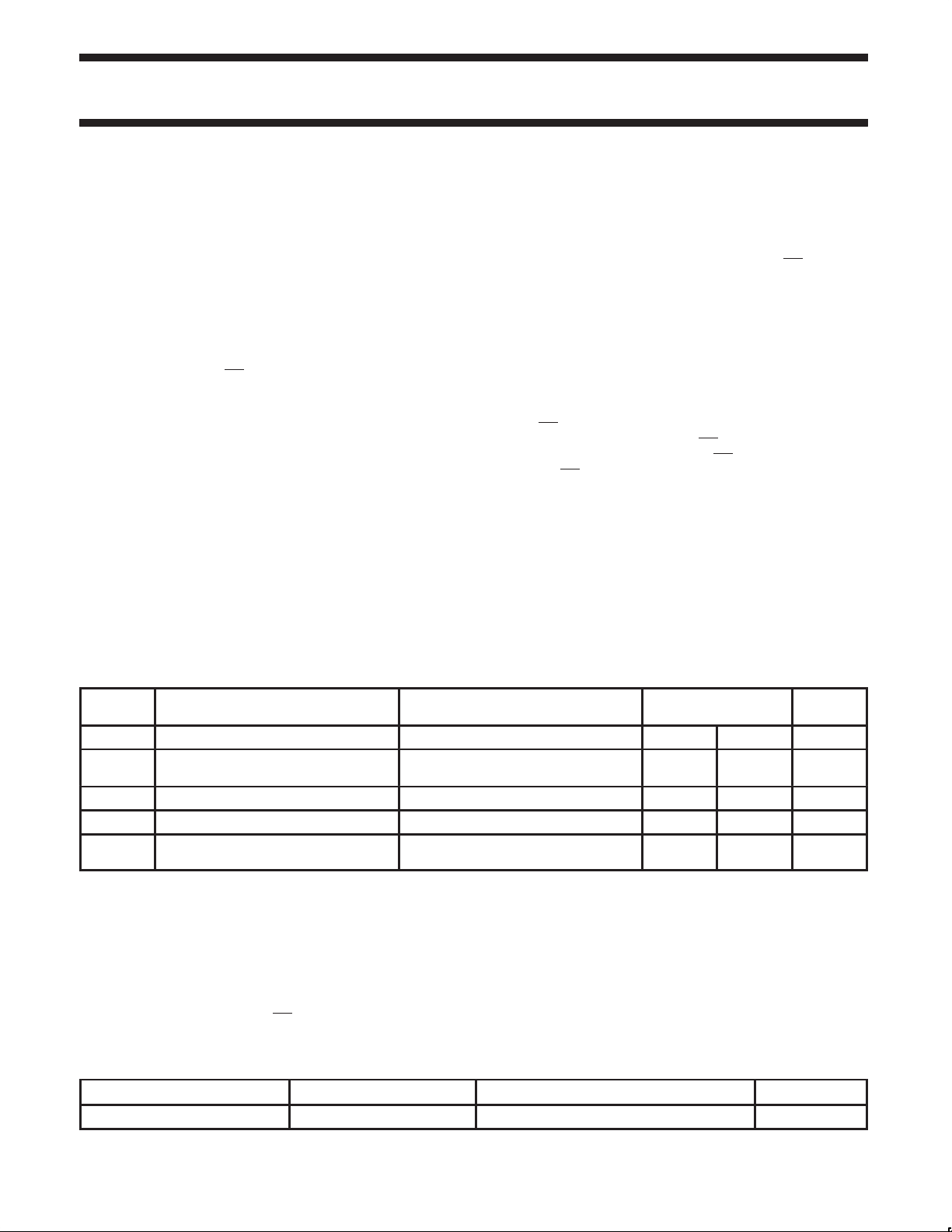
QUICK REFERENCE DATA
GND = 0V; T
SYMBOL
t
PLH
t
PHL
f
max
C
I
C
PD
NOTES:
is used to determine the dynamic power dissipation (PD in µW):
C
PD
P
D
where:
f
I
f
O
V
CC
C
L
I
pull-up
For HC and HCT an external clock is applied to X1 with:
= tf 6ns, VI is GND to VCC, MR = HIGH.
t
r
I
pull-up
= 25°C, tr = tf = 6ns
amb
PARAMETER
Propagation delay
X1 to OUT (S1 = S2 = LOW)
Maximum clock frequency 150 150 MHz
Input capacitance except X1 and X2 3.5 3.5 pF
Power dissipation
capacitance per package
=(CPD V
= inputfrequency in MHz..
= output frequency in MHz.
= Supply voltage in V .
= Output load capacitance in pF.
= Pull-up currents in µA.
is the summation of –II (µA) of S1 and S2 inputs at the LOW state.
2
fI) + (CL + V
CC
2
fO) + (I
CC
pull-up
VCC)
CONDITIONS
= 25°C; GND = 0V
T
amb
CL = 50pF; VCC = 5V 8 8 ns
TYPICAL UNIT
HC HCT
ORDERING INFORMATION
PACKAGES TEMPERATURE RANGE ORDER NUMBER DWG NUMBER
8-Pin Plastic SO 0°C to +70°C 74HC/HCT9323A D SOT96-1
pF
1995 Oct 27
2
Page 3
Philips Semiconductors Objective specification
Programmable ripple counter with oscillator
(3-State)
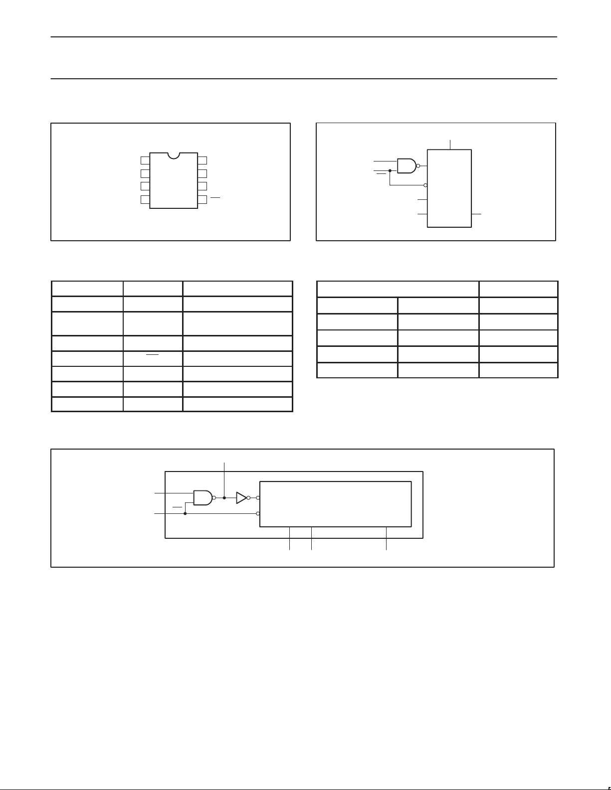
PIN CONFIGURATION
1
OUT
2
S2
3
S1
45
GND
PIN DESCRIPTION
PIN NUMBER SYMBOL FUNCTION
1 OUT Counter output
3, 2 S1-S2
4 GND Ground (0V)
5 MR Master reset (active LOW)
6 X2 Oscillator pin
7 X1 Clock input/oscillator pin
8 V
CC
V
8
CC
7
X1
6
X2
MR
SK00013
Mode select inputs for
divide by 1, 2, 4 or 8
Positive supply voltage
IEC LOGIC SYMBOL
X1
7
5
MR
FUNCTION TABLE
INPUTS OUTPUTS
S1 S2 OUT
0 0 f
0 1 fI/2
1 0 fI/4
1 1 fI/8
74HC/HCT9323A
6
X2
CP
C
D
3
S1
21
S2 OUT
SK00014
I
FUNCTIONAL DIAGRAM
7
5 MR
6
X2
X1
CP
C
D
3-STAGE BINARY COUNTER
AND DECODER
S1 S2 OUT
32 1
SK00015
1995 Oct 27
3
Page 4
Philips Semiconductors Objective specification
Programmable ripple counter with oscillator
(3-State)
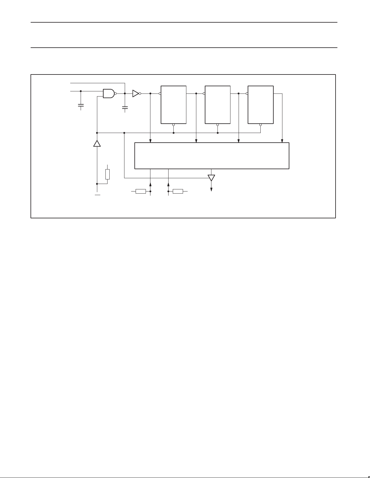
LOGIC DIAGRAM
X2
X1
2pF
V
CC
MR
2pF
V
CC
V
CC
V
CC
CP Q
FF
R
74HC/HCT9323A
CP Q
FF
R
DECODER
V
CC
OUT
CP Q
FF
R
Internal capacitors typical 2pF each, including stray capacitors on pins X1 and X2,
total capacitance will be typical 7pF per pin
SK00016
1995 Oct 27
4
Page 5
Philips Semiconductors Objective specification
Programmable ripple counter with oscillator
74HC/HCT9323A
(3-State)
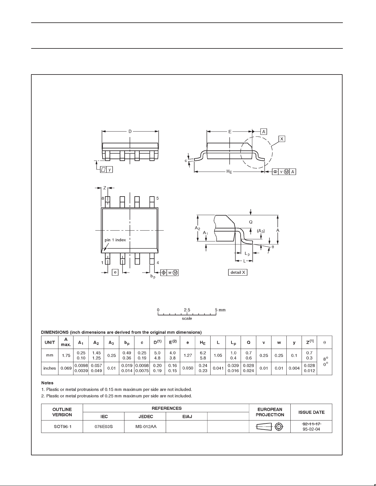
SO8: plastic small outline package; 8 leads; body width 3.9mm SOT96-1
1995 Oct 27
5
Page 6

Philips Semiconductors Objective specification
Programmable ripple counter with oscillator
(3-State)
74HC/HCT9323A
DEFINITIONS
Data Sheet Identification Product Status Definition
Objective Specification
Preliminary Specification
Product Specification
Formative or in Design
Preproduction Product
Full Production
Philips Semiconductors and Philips Electronics North America Corporation reserve the right to make changes, without notice, in the products,
including circuits, standard cells, and/or software, described or contained herein in order to improve design and/or performance. Philips
Semiconductors assumes no responsibility or liability for the use of any of these products, conveys no license or title under any patent, copyright,
or mask work right to these products, and makes no representations or warranties that these products are free from patent, copyright, or mask
work right infringement, unless otherwise specified. Applications that are described herein for any of these products are for illustrative purposes
only. Philips Semiconductors makes no representation or warranty that such applications will be suitable for the specified use without further testing
or modification.
LIFE SUPPORT APPLICA TIONS
Philips Semiconductors and Philips Electronics North America Corporation Products are not designed for use in life support appliances, devices,
or systems where malfunction of a Philips Semiconductors and Philips Electronics North America Corporation Product can reasonably be expected
to result in a personal injury. Philips Semiconductors and Philips Electronics North America Corporation customers using or selling Philips
Semiconductors and Philips Electronics North America Corporation Products for use in such applications do so at their own risk and agree to fully
indemnify Philips Semiconductors and Philips Electronics North America Corporation for any damages resulting from such improper use or sale.
Philips Semiconductors
811 East Arques Avenue
P.O. Box 3409
Sunnyvale, California 94088–3409
Telephone 800-234-7381
This data sheet contains the design target or goal specifications for product development. Specifications
may change in any manner without notice.
This data sheet contains preliminary data, and supplementary data will be published at a later date. Philips
Semiconductors reserves the right to make changes at any time without notice in order to improve design
and supply the best possible product.
This data sheet contains Final Specifications. Philips Semiconductors reserves the right to make changes
at any time without notice, in order to improve design and supply the best possible product.
Philips Semiconductors and Philips Electronics North America Corporation
register eligible circuits under the Semiconductor Chip Protection Act.
Copyright Philips Electronics North America Corporation 1995
All rights reserved. Printed in U.S.A.
 Loading...