

Page 1

INTEGRATED CIRCUITS
DATA SH EET
For a complete data sheet, please also download:
•The IC06 74HC/HCT/HCU/HCMOS Logic Family Specifications
•The IC06 74HC/HCT/HCU/HCMOS Logic Package Information
•The IC06 74HC/HCT/HCU/HCMOS Logic Package Outlines
74HC/HCT9015
Nine wide Schmitt trigger buffer/line
driver
Product specification
Supersedes data of March 1988
File under Integrated Circuits, IC06
December 1990
Page 2

Philips Semiconductors Product specification
Nine wide Schmitt trigger buffer/line driver 74HC/HCT9015
FEATURES
• Schmitt trigger action on all data inputs
• Output capability: standard
• ICCcategory: MSI
The 74HC/HCT9015 are nine wide Schmitt trigger
buffer/line drivers with Schmitt trigger inputs. These inputs
transform slowly changing input signals into sharply
defined jitter-free output signals.
The “9015” is identical to the “9014” but has non-inverting
inputs.
GENERAL DESCRIPTION
The 74HC/HCT9015 are high-speed Si-gate CMOS
devices and are pin compatible with low power Schottky
TTL (LSTTL). They are specified in compliance with
JEDEC standard no. 7A.
QUICK REFERENCE DATA
GND = 0 V; T
=25°C; tr=tf= 6 ns
amb
SYMBOL PARAMETER CONDITIONS
t
PHL
C
C
I
PD
/ t
PLH
propagation delay Anto Y
n
CL= 15 pF; VCC= 5 V 12 13 ns
input capacitance 3.5 3.5 pF
power dissipation capacitance per buffer notes 1 and 2 30 32 pF
Notes
1. C
is used to determine the dynamic power dissipation (PDin µW):
PD
PD=CPD× V
2
× fi+∑(CL× V
CC
2
× fo) where:
CC
fi= input frequency in MHz
fo= output frequency in MHz
∑ (CL× V
2
× fo) = sum of outputs
CC
CL= output load capacitance in pF
VCC= supply voltage in V
2. For HC the condition is VI= GND to V
CC
For HCT the condition is VI= GND to VCC− 1.5 V
TYPICAL
UNIT
HC HCT
ORDERING INFORMATION
“74HC/HCT/HCU/HCMOS Logic Package Information”
See
December 1990 2
.
Page 3
Philips Semiconductors Product specification
Nine wide Schmitt trigger buffer/line driver 74HC/HCT9015
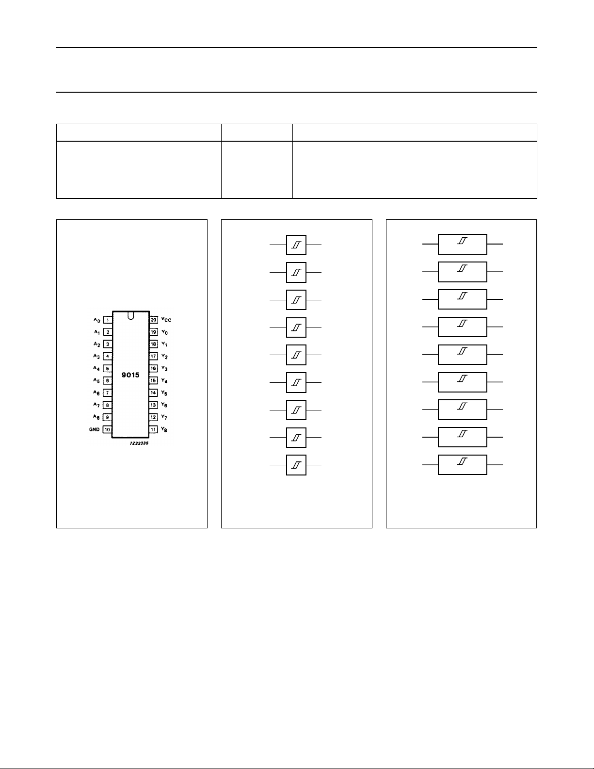
PIN DESCRIPTION
PIN NO. SYMBOL NAME AND FUNCTION
1, 2, 3, 4, 5, 6, 7, 8, 9 A
10 GND ground (0 V)
19, 18, 17, 16, 15, 14, 13, 12, 11 Y
20 V
0
0
CC
to A
to Y
8
8
data inputs
data outputs
positive supply voltage
page
A
0
1
A
1
2
A
2
3
A
3
4
A
4
5
A
5
6
A
6
7
A
7
8
A
8
9
Y
Y
Y
Y
Y
Y
Y
Y
Y
MBA016
0
19
1
18
2
17
3
16
4
15
5
14
6
13
7
12
8
11
Fig.1 Pin configuration. Fig.2 Logic symbol.
age
1
218
3
4
5
6
7
8
9
MBA013
19
17
16
15
14
13
12
11
Fig.3 IEC logic symbol.
December 1990 3
Page 4
Philips Semiconductors Product specification
Nine wide Schmitt trigger buffer/line driver 74HC/HCT9015
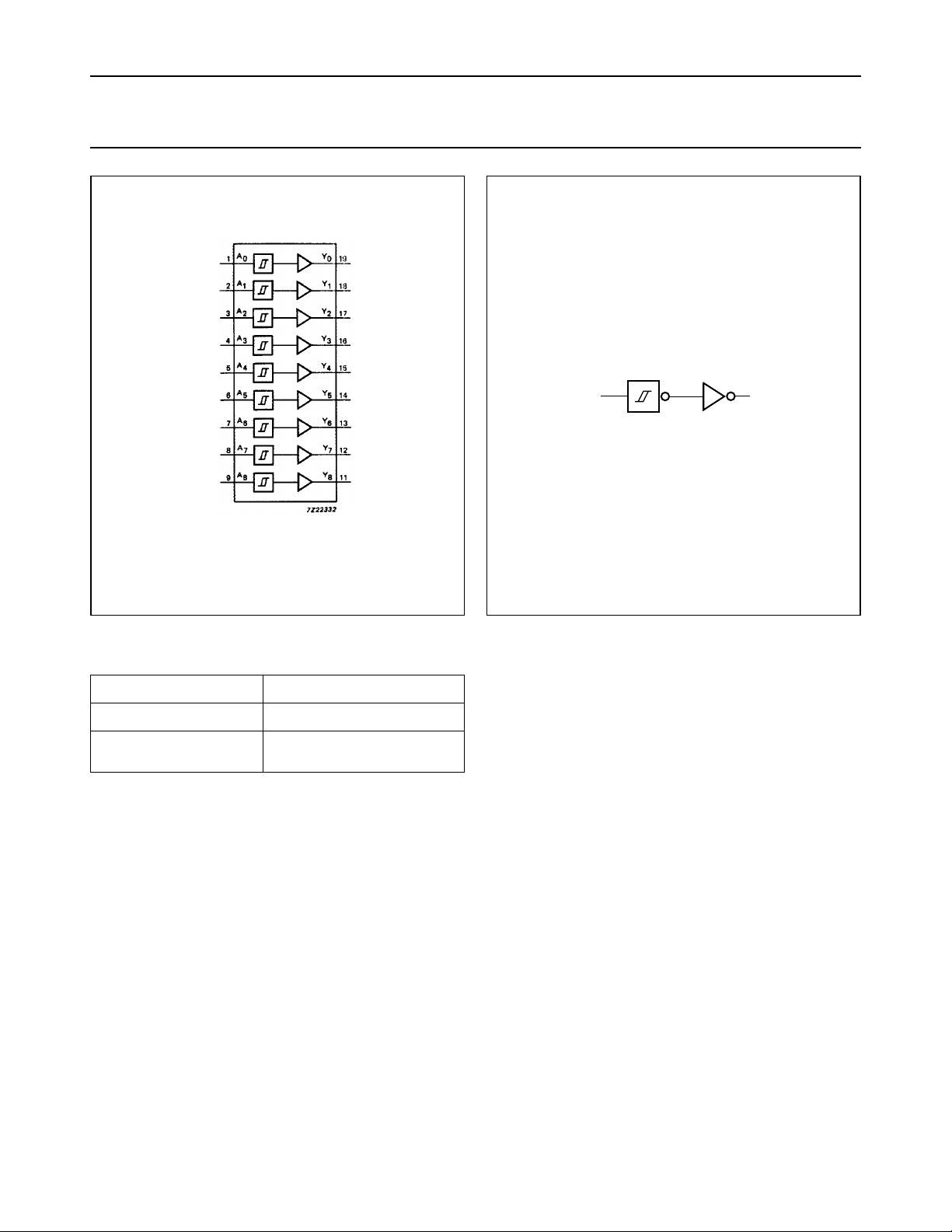
Fig.4 Functional diagram. Fig.5 Logic diagram (one Schmitt trigger).
FUNCTION TABLE
INPUTS OUTPUTS
A
n
L
H
Notes
1. H = HIGH voltage level
L = LOW voltage level
handbook, halfpage
Y
n
A
n
MBA017
Y
n
L
H
December 1990 4
Page 5
Philips Semiconductors Product specification
Nine wide Schmitt trigger buffer/line driver 74HC/HCT9015
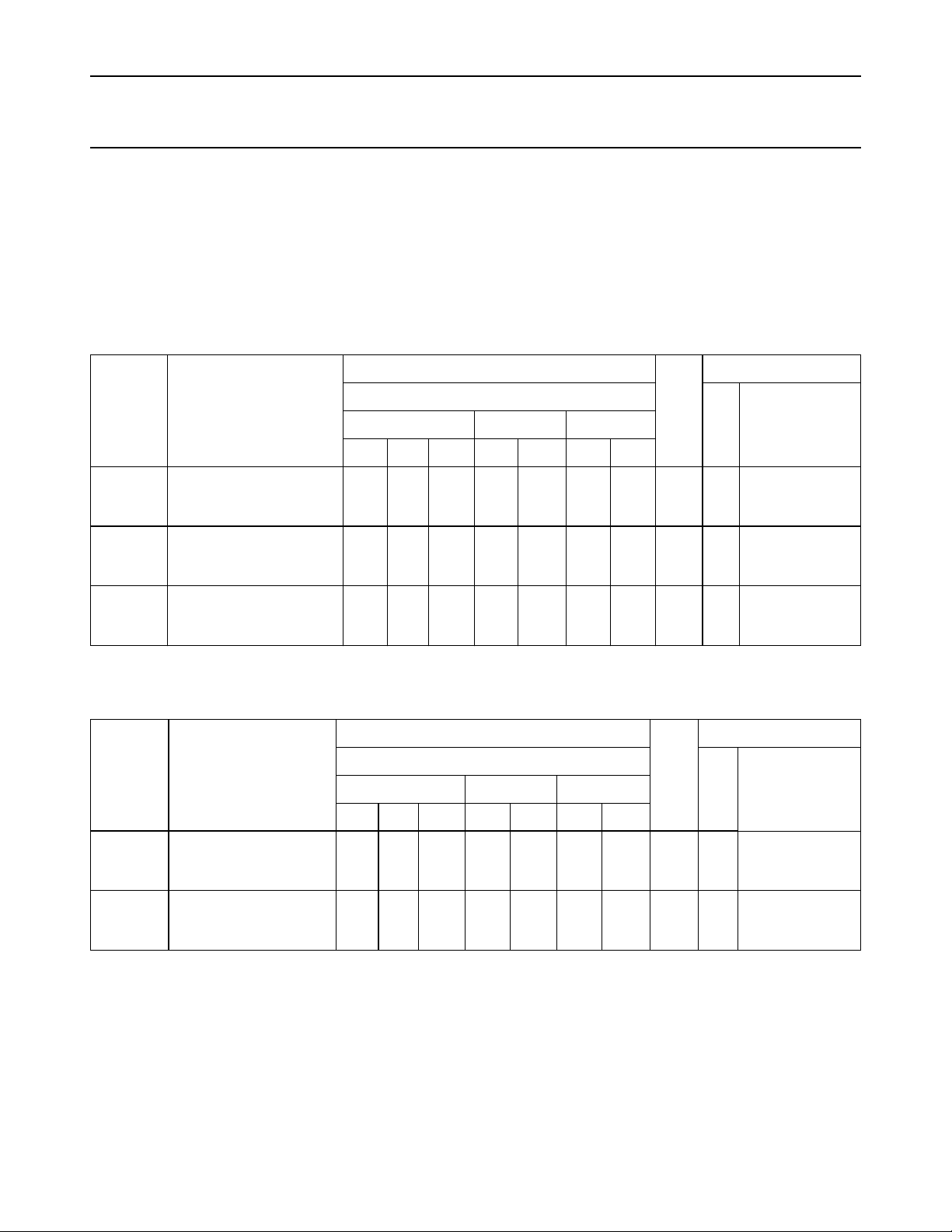
DC CHARACTERISTICS FOR 74HC
For the DC characteristics see
“74HC/HCT/HCU/HCMOS Logic Family Specifications”
Transfer characteristics are given below.
Output capability: standard
ICCcategory: MSI
TRANSFER CHARACTERISTICS FOR 74HC
Voltages are referred to GND (ground = 0 V)
SYMBOL PARAMETER
min. typ. max. min. max. min. max.
V
T+
positive-going threshold 0.70
1.75
2.30
V
T−
negative-going threshold 0.30
1.35
1.80
V
H
hysteresis (VT+− VT−) 0.2
0.4
0.5
1.13
2.37
3.11
0.70
1.80
2.43
0.43
0.57
0.68
1.50
3.15
4.20
1.10
2.40
3.30
0.80
1.00
1.10
T
amb
0.70
1.75
2.30
0.30
1.35
1.80
0.18
0.40
0.50
(°C)
74HC
1.50
3.15
4.20
1.10
2.40
3.30
0.80
1.00
1.10
0.70
1.75
2.30
0.30
1.35
1.80
0.15
0.40
0.50
1.50
3.15
4.20
1.10
2.40
3.30
0.80
1.00
1.10
.
UNIT
V 2.0
V 2.0
V 2.0
TEST CONDITIONS
V
CC
WAVEFORMS+25 −40 to +85 −40 to +125
(V)
Figs 6 and 7
4.5
6.0
Figs 6 and 7
4.5
6.0
Fig.6
4.5
6.0
AC CHARACTERISTICS FOR 74HC
GND = 0 V; t
= 6 ns; CL= 50 pF
r=tf
SYMBOL PARAMETER
t
PHL
t
THL
/ t
/ t
propagation delay
PLH
Anto Y
n
output transition time 19
TLH
(°C)
T
amb
74HC
min. typ. max. min. max. min. max.
33
12
10
7
6
105
21
18
75
15
13
130
26
22
95
19
16
160
32
27
110
22
19
UNIT
V
(V)
ns 2.0
4.5
6.0
ns 2.0
4.5
6.0
TEST CONDITIONS
CC
WAVEFORMS+25 −40 to +85 −40 to +125
Fig.8
Fig.8
December 1990 5
Page 6
Philips Semiconductors Product specification
Nine wide Schmitt trigger buffer/line driver 74HC/HCT9015
DC CHARACTERISTICS FOR 74HCT
For the DC characteristics see
“74HC/HCT/HCU/HCMOS Logic Family Specifications”
.
Transfer characteristics are given below.
Output capability: standard
ICCcategory: MSI
Note to HCT types
The value of additional quiescent supply current (∆ICC) for a unit load of 1 is given in the family specifications.
To determine ∆I
per input, multiply this value by the unit load coefficient shown in the table below.
CC
INPUT UNIT LOAD COEFFICIENT
A
n
0.3
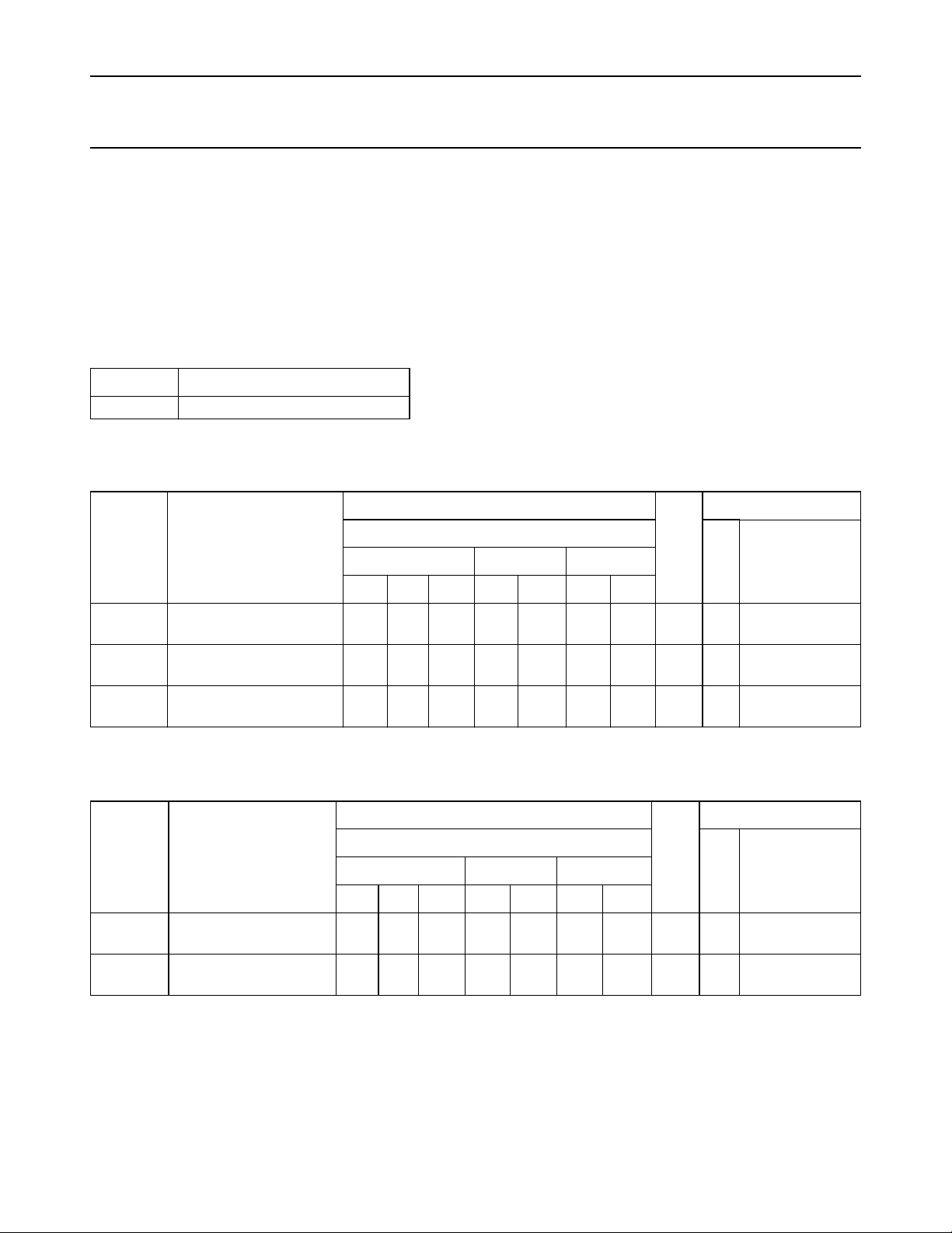
TRANSFER CHARACTERISTICS FOR 74HCT
Voltages are referred to GND (ground = 0 V)
T
amb
(°C)
TEST CONDITIONS
74HCT
SYMBOL PARAMETER
UNIT
V
(V)
CC
WAVEFORMS+25 −40 to +85 −40 to +125
min. typ. max. min. max. min. max.
0.9
1.50
2.0
0.9
V
T+
V
T−
V
H
positive-going threshold
negative-going threshold
hysteresis (VT+− VT−)
1.2
0.7
0.8
0.2
0.2
1.70
1.06
1.27
0.44
0.44
2.1
1.4
1.7
0.8
0.8
1.2
0.7
0.8
0.2
0.2
2.0
2.1
1.4
1.7
0.8
0.8
0.9
1.2
0.7
0.8
0.2
0.2
2.0
2.1
1.4
2.7
0.8
0.8
V
V
V
4.5
5.5
4.5
5.5
4.5
5.5
Figs 6 and 7
Figs 6 and 7
Figs 6 and 7
AC CHARACTERISTICS FOR 74HCT
GND = 0 V; t
= 6 ns; CL= 50 pF
r=tf
T
SYMBOL PARAMETER
min. typ. max. min. max. min. max.
t
PHL
t
THL
/ t
/ t
propagation delay
PLH
Anto Y
output transition time
TLH
n
18 32 40 48 ns 4.5 Fig.8
7 15 19 22 ns 4.5 Fig.8
December 1990 6
(°C)
amb
74HCT
UNIT
TEST CONDITIONS
V
CC
WAVEFORMS+25 −40 to +85 −40 to +125
(V)
Page 7
Philips Semiconductors Product specification
Nine wide Schmitt trigger buffer/line driver 74HC/HCT9015
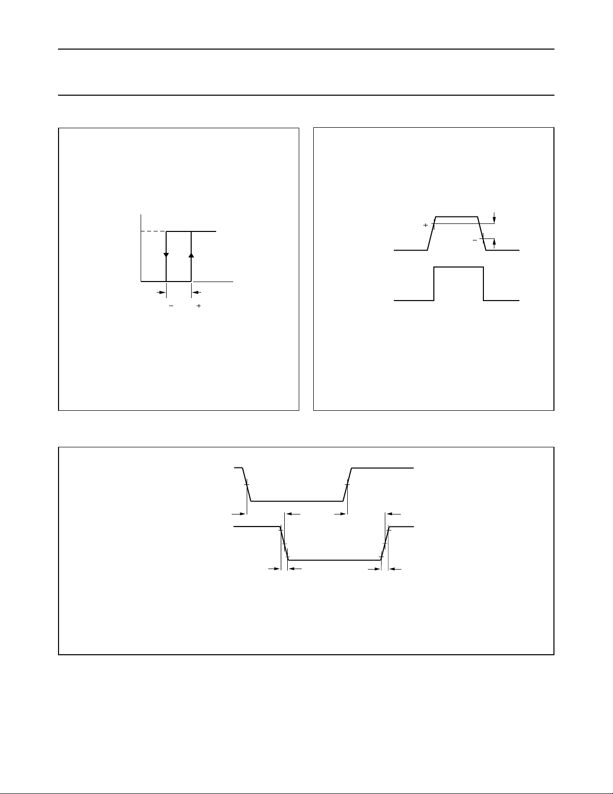
TRANSFER CHARACTERISTIC WAVEFORMS
handbook, halfpage
V
Fig.6 Transfer characteristic.
AC WAVEFORMS
handbook, full pagewidth
O
V
H
V
T
MBA325
V
I
V
T
handbook, halfpage
V
V
I
V
O
T
V
V
H
T
MBA324
Fig.7 Waveforms showing the definition of VT+,
VT−and VH.
(1)
AnINPUT
V
M
t
PLH
t
TLH
YnOUTPUT
MBA019
(1) HC : VM= 50%; VI= GND to VCC.
= 1.3 V; VI= GND to 3 V.
HCT: V
M
t
t
THL
PHL
(1)
V
M
Fig.8 Waveforms showing the input (An) to output (Yn) propagation delays and the output transition times.
PACKAGE OUTLINES
“74HC/HCT/HCU/HCMOS Logic Package Outlines”
See
.
December 1990 7
 Loading...