

Page 1

INTEGRATED CIRCUITS
DATA SH EET
For a complete data sheet, please also download:
•The IC06 74HC/HCT/HCU/HCMOS Logic Family Specifications
•The IC06 74HC/HCT/HCU/HCMOS Logic Package Information
•The IC06 74HC/HCT/HCU/HCMOS Logic Package Outlines
74HC/HCT7404
5-Bit x 64-word FIFO register;
3-state
Product specification
Supersedes data of October 1990
File under Integrated Circuits, IC06
September 1993
Page 2

Philips Semiconductors Product specification
5-Bit x 64-word FIFO register; 3-state 74HC/HCT7404
FEATURES
• Synchronous or asynchronous operation
• 3-state outputs
• 30 MHz (typical) shift-in and shift-out rates
• Readily expandable in word and bit dimensions
• Pinning arranged for easy board layout: input pins
directly opposite output pins
• Output capability: driver (8 mA)
• ICC category: LSI.
GENERAL DESCRIPTION
The 74HC/HCT7404 are high-speed Si-gate CMOS
devices specified in compliance with JEDEC standard
no.7A.
The “7404” is an expandable, First-In First-Out (FIFO)
memory organized as 64 words by 5 bits. A guaranteed
15 MHz data-rate makes it ideal for high-speed
applications. A higher data-rate can be obtained in
applications where the status flags are not used
(burst-mode).
With separate controls for shift-in (SI) and shift-out (
APPLICATIONS
• High-speed disc or tape controller
• Communications buffer.
reading and writing operations are completely
independent, allowing synchronous and asynchronous
data transfers. Additional controls include a master-reset
input (MR), an output enable input (OE) and flags. The
data-in-ready (DIR) and data-out-ready (DOR) flags
indicate the status of the device.
QUICK REFERENCE DATA
GND = 0 V; T
= 25 °C; tr = tf = 6 ns.
amb
SYMBOL PARAMETER CONDITIONS
t
PHL/tPLH
f
max
C
I
C
PD
propagation delay SO, SI to DIR and DOR CL = 15 pF; VCC = 5 V 15 17 ns
maximum clock frequency 30 30 MHz
input capacitance 3.5 3.5 pF
power dissipation capacitance per package note 1 475 490 pF
SO),
TYP.
UNIT
HC HCT
Note
1. For HC the condition is V
= GND to VCC.
I
For HCT the condition is VI = GND to VCC−1.5 V.
ORDERING INFORMATION
EXTENDED
TYPE NUMBER
PINS PIN POSITION MATERIAL CODE
PACKAGE
74HC/HCT7404N 18 DIL plastic SOT102
74HC/HCT7404D 20 SO20 plastic SOT163A
September 1993 2
Page 3

Philips Semiconductors Product specification
5-Bit x 64-word FIFO register; 3-state 74HC/HCT7404
PINNING (SOT102)
SYMBOL PIN DESCRIPTION
OE 1 output enable input (active
LOW)
DIR 2 data-in-ready output
SI 3 shift-in input (active HIGH)
D
to D
O
4, 5, 6, 7, 8 parallel data inputs
4
GND 9 ground
MR 10 asynchronous master-reset
input (active LOW)
Q
to Q
4
0
11, 12, 13,
data outputs
14, 15
DOR 16 data-out-ready output
SO 17 shift-out input (active LOW)
V
CC
18 positive supply voltage
PINNING (SOT163A)
SYMBOL PIN DESCRIPTION
OE 1 output enable input (active
LOW)
DIR 2 data-in-ready output
SI 3 shift-in input (active HIGH)
n.c. 4 not connected
D
to D
0
5, 6, 7, 8, 9 parallel data inputs
4
GND 10 ground
MR 11 asynchronous master-reset
input (active LOW)
Q
to Q
4
0
12, 13, 14,
data outputs
15, 16
n.c. 17 not connected
DOR 18 data-out ready output
n.c. 19 not connected
V
CC
20 positive supply voltage
handbook, halfpage
OE
DIR
D
D
D
D
D
GND
1
2
SI
3
4
0
5
1
2
3
4
7404
6
7
8
9
MGA670
V
18
CC
17
SO
DOR
16
Q
15
0
Q
14
1
Q
13
2
Q
12
3
Q
11
4
10
MR
Fig.1 Pin configuration (SOT102).
handbook, halfpage
OE
DIR
n.c.
D
D
D
D
D
GND
1
2
3
SI
4
5
0
1
2
3
4
7404
6
7
8
9
10
MGA671
V
20
CC
19
SO
18
DOR
n.c.
17
16
Q
0
Q
15
1
Q
14
2
Q
13
3
Q
12
4
11
MR
Fig.2 Pin configuration (SOT163).
September 1993 3
Page 4

Philips Semiconductors Product specification
5-Bit x 64-word FIFO register; 3-state 74HC/HCT7404
D
D
D
D
D
SI
SO
0
1
2
3
4
10 (11)
1 (1)
OE
MR
Q
Q
Q
Q
Q
DOR
DIR
15 (16)
0
14 (15)
1
13 (14)
2
12 (13)
3
11 (12)
4
16 (18)
2 (2)
MGA673
handbook, halfpage
(5) 4
(6) 5
(7) 6
(8) 7
(9) 8
(3) 3
(19) 17
Pin numbers between parentheses refer to the SO package.
Fig.3 Logic symbol.
handbook, halfpage
(1) 1
(3) 3
(11) 10
(19) 17
(5) 4
(6) 5
(7) 6
(8) 7
(9) 8
Pin numbers between parentheses refer to the SO package.
EN4
1Z3
1 ( /C2)
CT = 0
5
5Z6
2D
FIFO 64 x 5
CTR
<
CT 64
CT 0
>
[IR] 3
[OR] 6
G1
G5
4
MGA675
Fig.4 IEC logic symbol.
2 (2)
16 (18)
15 (16)
14 (15)
13 (14)
12 (13)
11 (12)
handbook, full pagewidth
(5) 4
D
0
(6) 5
D
1
(7) 6
D
2
(8) 7
D
INPUT
3
D
MR
4
STAGE
1 x 5 BITS
DIR
(9) 8
(11) 10
Pin numbers between parentheses refer to the SO package.
MAIN FIFO
REGISTER
62 x 5 BITS
CONTROL LOGIC
SI DOR SO
Fig.5 Functional diagram.
September 1993 4
OUTPUT
STAGE
1 x 5 BITS
16 (18)2 (2) 1 (1) 3 (3)
17 (19)
OE
OE
Q
15 (16)
0
14 (15)
Q
1
13 (14)
Q
2
12 (13)
Q
3
11 (12)
Q
4
MGA680
Page 5

Philips Semiconductors Product specification
5-Bit x 64-word FIFO register; 3-state 74HC/HCT7404
DOR
ull pagewidth
SO
FP
(1)
R
SQ
R
61 x
FB
(1)
R
(2)
FF64
R
RQ
to
FF3
FF63
R
RQ
SQ
SQ
SQ
OE
Q0Q
CL CL
CL CL
1
3-STATE
5
5
OUTPUT
LATCHES
LATCHES
Q3Q
BUFFER
4
MSB117
position 64
position 3 to 63
Fig.6 Logic diagram.
(2)
FF2
RQ
SQ
R
(2)
FF1
SQ
RQ
R
FS
MR
(1)
SI
SQ
R
September 1993 5
DIR
5
CL CL
CL CL
D0D1D3D
LATCHES
5
LATCHES
4
position 2
position 1
LOW on R input of FF1 to FF64 will set Q output to LOW independent of state on S input.
(See control flip-flops)
LOW on S input of flip-flops FS, FB and FP will set Q output to HIGH independent of state on R input.
Page 6

Philips Semiconductors Product specification
5-Bit x 64-word FIFO register; 3-state 74HC/HCT7404
FUNCTIONAL DESCRIPTION
The DIR flag indicates the input stage
status, either empty and ready to
receive data (DIR = HIGH) or full and
busy (DIR = LOW). When DIR and SI
are HIGH, data present at D0 to D4 is
shifted into the input stage; once
complete DIR goes LOW. When SI is
set LOW, data is automatically shifted
to the output stage or to the last
empty location. A FIFO which can
receive data is indicated by DIR set
HIGH.
A DOR flag indicates the output stage
status, either data available
(DOR = HIGH) or busy
outputs (Q
new data may be shifted into the
output stage, once complete DOR is
set LOW.
Expanded Format (see Fig.18) The DOR and DIR signals are used to
allow the ‘7404’ to be cascaded. Both
parallel and serial expansion is
possible. Serial expansion is only
possible with typical devices.
Parallel Expansion
Parallel expansion is accomplished
by logically ANDing the DOR and DIR
signals to form a composite signal.
to Q4). When SO is LOW
0
Serial Expansion
Serial expansion is accomplished by:
• tying the data outputs of the first
device to the data inputs of the
second device
• connecting the DOR pin of the first
device to the SI pin of the second
device
• connecting the
device to the DIR pin of the second
device.
(DOR = LOW). When SO and DOR
are HIGH, data is available at the
DC CHARACTERISTICS FOR 74HC
For the DC characteristics see
“74HC/HCT/HCU/HCMOS Logic Family Specifications”
Output capability: parallel outputs, bus driver; serial output, standard ICC category: MSI
SO pin of the first
.
Output capability: driver 8 mA
ICC category: LSI
Voltages are referenced to GND (ground = 0 V).
DC CHARACTERISTICS FOR 74HC
SYMBOL PARAMETER
+25 −40 to +85 −40 to +125
MIN TYP MAX MIN MAX MIN MAX
V
OH
V
OL
HIGH level
output voltage
LOW level
output voltage−−
3.98
5.48
4.32
5.81−−
0.15
0.15
T
0.26
0.26−−
°C
amb
3.84
5.34−−
0.33
0.33−−
3.70
5.20−−
0.4
0.4
UNIT
V
V
V
V
TEST CONDITION
V
CC
V
or
V
or
V
I
IH
IL
IH
IL
IO = −8 mA
IO = −10 mA
IO = 8 mA
IO = 10 mA
(V)
4.56V
4.56V
OTHER
September 1993 6
Page 7

Philips Semiconductors Product specification
5-Bit x 64-word FIFO register; 3-state 74HC/HCT7404
AC CHARACTERISTICS FOR 74HC
GND = 0 V; t
= tf = 6 ns; CL = 50 pF.
r
SYMBOL PARAMETER
t
PHL/tPLH
propagation
delay
MR to DIR,
DOR
t
PHL
propagation
delay
t
PHL/tPLH
MR to Q
propagation
n
delay
SI to DIR
t
PHL/tPLH
propagation
delay
SO to DOR
t
PHL/tPLH
propagation
delay
t
PHL/tPLH
DOR to Q
propagation
n
delay
t
PLH
SO to Q
propagation
n
delay/ripple
through delay
SI to DOR
t
PLH
propagation
delay/bubble-up
delay SO to
DIR
t
PZH/tPZL
3-state output
enable
t
PHZ/tPLZ
OE to Q
3-state output
n
disable
t
THL/tTLH
OE to Q
output transition
n
time
t
W
SI pulse width
HIGH or LOW357
t
W
SO pulse width
HIGH or LOW7014
°C
T
amb
+25 −40 to +85 −40 to +125
MIN TYP MAX MIN MAX MIN MAX
−
−
−
−
−
−
−
−
−
−
−
−
−
−
−
−
−
−
−
−
−
−
−
−
−
−
−
−
−
−
−
−
−
6
12
69
25
20
52
19
15
66
24
19
94
34
27
11
4
3
105
38
30
2.2
0.8
0.6
2.8
1.0
0.8
44
16
13
50
18
14
14
5
4
11
4
3
22
8
6
210
42
36
160
32
27
205
41
35
290
58
49
35
7
6.0
325
65
55
7.0
1.4
1.2
9.0
1.8
1.5
150
30
26
150
30
26
60
12
10
−
−
−
−
−
−
−
−
−
−
−
−
−
−
−
−
−
−
−
−
−
−
−
−
−
−
−
−
−
−
−
−
−
−
−
−
−
−
−
45
9
8
90
18
15
265
53
45
200
40
34
255
51
43
365
73
62
45
9
8
406
81
69
8.8
1.8
1.5
11.2
2.2
1.9
190
38
32
190
38
33
75
15
13
−
−
−
−
−
−
−
−
−
−
−
−
−
−
−
−
−
−
−
−
−
−
−
−
−
−
−
−
−
−
−
−
−
−
−
−
−
−
−
55
11
9
105
21
18
315
63
54
240
48
41
310
62
53
435
87
74
55
11
9
488
98
83
10.5
2.1
1.8
13.5
2.7
2.3
225
45
38
225
45
38
90
18
15
−
−
−
−
−
−
UNIT
ns
ns
ns
ns
ns
ns
ns
ns
ns
ns
ns
ns
ns
ns
ns
ns
ns
ns
µs
µs
µs
µs
µs
µs
ns
ns
ns
ns
ns
ns
ns
ns
ns
ns
ns
ns
ns
ns
ns
TEST CONDITION
V
CC
(V)
2.0
WAVEFORMS
Fig.9
4.5
6.0
2.0
Fig.9
4.5
6.0
2.0
Fig.7
4.5
6.0
2.0
Fig.10
4.5
6.0
2.0
Fig.11
4.5
6.0
2.0
Fig.15
4.5
6.0
2.0
Fig.16
4.5
6.0
2.0
Fig.8
4.5
6.0
2.0
Fig.17
4.5
6.0
2.0
Fig.17
4.5
6.0
2.0
Fig.17
4.5
6.0
2.0
Fig.7
4.5
6.0
2.0
Fig.10
4.5
6.0
September 1993 7
Page 8

Philips Semiconductors Product specification
5-Bit x 64-word FIFO register; 3-state 74HC/HCT7404
T
SYMBOL PARAMETER
t
W
DIR pulse width
HIGH
t
W
DOR pulse
width HIGH
t
W
MR pulse
width LOW
t
rem
removal time
MR to SI
t
su
set-up time
Dn to SI
t
h
hold time
Dn to SI
f
max
maximum clock
pulse frequency
SI, SO burst
mode
f
max
maximum clock
pulse frequency
SI, SO using
flags
f
max
maximum clock
pulse frequency
SI, SO
cascaded
°C
amb
+25 −40 to +85 −40 to +125
MIN TYP MAX MIN MAX MIN MAX
10
5
4
14
7
6
120
24
20
80
16
14
−8
−4
−3
135
27
23
3.6
18
21
3.6
18
21
−
−
−
41
15
12
52
19
15
39
14
11
24
8
7
−36
−13
−10
44
16
13
9.9
30
36
9.9
30
36
7.6
23
27
130
26
22
160
32
27
−
−
−
−
−
−
−
−
−
−
−
−
−
−
−
−
−
−
−
−
−
8
4
3
12
6
5
150
30
26
100
20
17
−6
−3
−3
170
34
29
2.8
14
16
2.8
14
16
−
−
−
165
33
28
200
40
34
−
−
−
−
−
−
−
−
−
−
−
−
−
−
−
−
−
−
−
−
−
8
4
3
12
6
5
180
36
31
120
24
20
−6
−3
−3
205
41
35
2.4
12
14
2.4
12
14
−
−
−
195
39
33
240
48
41
−
−
−
−
−
−
−
−
−
−
−
−
−
−
−
−
−
−
−
−
−
UNIT
ns
ns
ns
ns
ns
ns
ns
ns
ns
ns
ns
ns
ns
ns
ns
ns
ns
ns
MHz
MHz
MHz
MHz
MHz
MHz
MHz
MHz
MHz
TEST CONDITION
V
CC
(V)
2.0
WAVEFORMS
Fig.8
4.5
6.0
2.0
Fig.11
4.5
6.0
2.0
Fig.9
4.5
6.0
2.0
Fig.16
4.5
6.0
2.0
Fig.14
4.5
6.0
2.0
Fig.14
4.5
6.0
2.0
4.5
Fig.12 and
Fig.13
6.0
2.0
4.5
Fig.7 and
Fig.10
6.0
2.0
4.5
Fig.7 and
Fig.10
6.0
September 1993 8
Page 9

Philips Semiconductors Product specification
5-Bit x 64-word FIFO register; 3-state 74HC/HCT7404
DC CHARACTERISTICS FOR 74HCT
For the DC characteristics see
“74HC/HCT/HCU/HCMOS Logic Family Specifications”
, except that VOH and VOL are not
valid for driver output. They are replaced by the values given below.
Output capability: driver 8 mA
ICC category: LSI.
Voltages are referenced to GND (ground = 0 V).
DC CHARACTERISTICS FOR 74HCT
T
SYMBOL PARAMETER
V
OH
HIGH level
output voltage
V
OL
LOW level
output voltage
°C
amb
+25 −40 to +85 −40 to +125
UNIT
MIN TYP MAX MIN MAX MIN MAX
3.98 4.32 − 3.84 − 3.7 − V 4.5 V
− 0.15 0.26 − 0.33 − 0.40 V 4.5 V
TEST CONDITION
V
CC
V
(V)
IH
or
V
IL
IH
or
V
IL
Note to HCT types
The value of additional quiescent supply current (∆I
) for a unit load of 1 is given in the family specifications.
CC
To determine ∆ICC per input, multiply this value by the unit load coefficient shown in the table below.
I
IO = −8 mA
IO = 8 mA
OTHER
UNIT LOAD COEFFICIENT
INPUT UNIT LOAD COEFFICIENT
OE 1
SI 1.5
D
n
0.75
MR 1.5
SO 1.5
September 1993 9
Page 10
Philips Semiconductors Product specification
5-Bit x 64-word FIFO register; 3-state 74HC/HCT7404
AC CHARACTERISTICS FOR 74HCT
GND = 0 V; t
= tf = 6 ns; CL = 50 pF.
r
SYMBOL PARAMETER
t
PHL/tPLH
propagation
delay
MR to DIR,
DOR
t
PHL
propagation
delay
t
PHL/tPLH
MR to Q
propagation
n
delay
SI to DIR
t
PHL/tPLH
propagation
delay
SO to DOR
t
PHL/tPLH
propagation
delay
t
PHL/tPLH
SO to Q
propagation
n
delay
t
PLH
DOR to Q
propagation
n
delay/ripple
through delay
SI to DOR
t
PLH
propagation
delay/bubbleup delay
SO to DIR
t
PZH/tPZL
3-state output
enable
t
PHZ/tPLZ
OE to Q
3-state output
n
disable
t
THL/tTLH
OE to Q
output
n
transition time
t
W
SI pulse width
HIGH or LOW
t
W
SO pulse width
HIGH or LOW
t
W
DIR pulse width
HIGH
°C
T
amb
+25 −40 to +85 −40 to +125
MIN TYP MAX MIN MAX MIN MAX
UNIT
TEST CONDITION
V
CC
(V)
WAVEFORMS
− 30 51 − 53 − 63 ns 4.5 Fig.9
− 22 38 − 48 − 57 ns 4.5 Fig.9
− 25 43 − 54 − 65 ns 4.5 Fig.7
− 36 61 − 76 − 92 ns 4.5 Fig.10
− 42 72 − 90 − 108 ns 4.5 Fig.15
− 712−15 − 18 ns 4.5 Fig.11
− 0.8 1.4 − 1.75 − 2.1 µs 4.5 Fig.11
− 1 1.8 − 2.25 − 2.7 µs 4.5 Fig.8
− 16 30 − 38 − 45 ns 4.5 Fig.17
− 19 30 − 38 − 45 ns 4.5 Fig.17
− 512−15 − 18 ns 4.5 Fig.17
95−6−8−ns 4.5 Fig.7
14 8 − 18 − 21 − ns 4.5 Fig.10
5 17 29 4 36 4 44 ns 4.5 Fig.8
September 1993 10
Page 11
Philips Semiconductors Product specification
5-Bit x 64-word FIFO register; 3-state 74HC/HCT7404
T
SYMBOL PARAMETER
t
W
DOR pulse
width HIGH
t
W
MR pulse
width LOW
t
rem
removal time
MR to SI
t
su
set-up time
Dn to SI
t
h
hold time
Dn to SI
f
max
maximum
clock pulse
frequency
SI, SO burst
mode
f
max
maximum
clock pulse
frequency
SI, SO using
flags
f
max
maximum
clock pulse
frequency
SI, SO
cascaded
°C
amb
+25 −40 to +85 −40 to +125
UNIT
MIN TYP MAX MIN MAX MIN MAX
7 21 36 6 45 6 54 ns 4.5 Fig.11
26 15 − 33 − 39 − ns 4.5 Fig.9
18 10 − 23 − 27 − ns 4.5 Fig.16
−5 −16 −−4−−4−ns 4.5 Fig.14
30 18 − 38 − 45 − ns 45 Fig.14
18 30 − 14 − 12 − MHz 4.5 Fig.12 and Fig.13
18 30 − 14 − 12 − MHz 4.5 Fig.7 and Fig.10
− 23 −−−−−MHz 4.5 Fig.7 and Fig.10
TEST CONDITION
V
CC
(V)
WAVEFORMS
September 1993 11
Page 12

Philips Semiconductors Product specification
5-Bit x 64-word FIFO register; 3-state 74HC/HCT7404
AC WAVEFORMS
Shifting in sequence FIFO empty to FIFO full
handbook, full pagewidth
SI INPUT
DIR OUTPUT
Dn INPUT
(1) HC : VM= 50%; VI= GND to VCC.
HCT : V
= 1.3 V; VI= GND to 3 V.
M
1st word 2nd word 64th word
1/ f max
(1)
t
V
PLH
M
t
W
2
t
PHL
15
(1)
V
M
64
73
MGA659
Fig.7 Waveforms showing the SI input to DIR output propagation delay, the SI pulse width and SI maximum
pulse frequency.
Notes to Fig.7
1. DIR initially HIGH; FIFO is prepared for valid data
2. SI set HIGH; data loaded into input stage
3. DIR goes LOW, input stage “busy”
4. SI set LOW; data from first location “ripple through”
5. DIR goes HIGH, status flag indicates FIFO prepared for additional data
6. Repeat process to load 2nd word through to 64th word into FIFO
DIR remains LOW; with attempt to shift into full FIFO, no data transfer occurs.
September 1993 12
Page 13
Philips Semiconductors Product specification
5-Bit x 64-word FIFO register; 3-state 74HC/HCT7404
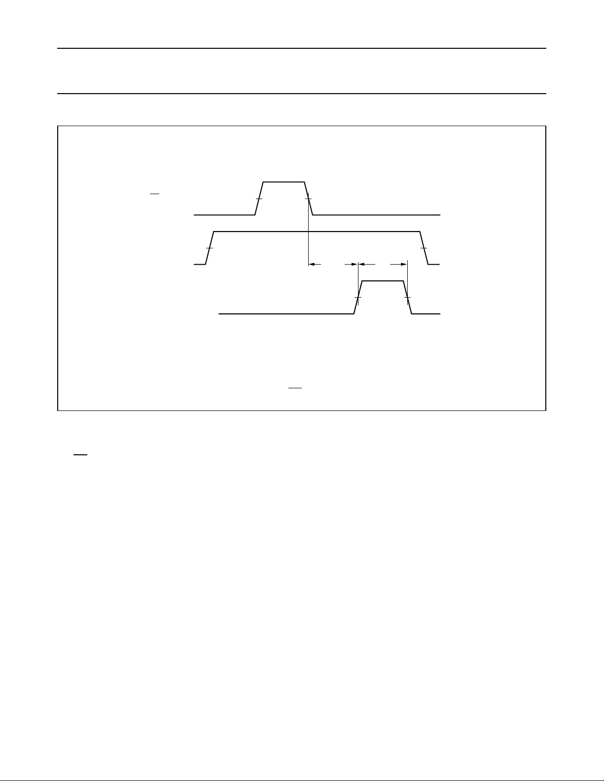
With FIFO full; SI held HIGH in anticipation of empty location
handbook, full pagewidth
SO INPUT
SI INPUT
DIR OUTPUT
(1) HC : VM= 50%; VI= GND to VCC.
HCT : V
= 1.3 V; VI= GND to 3 V.
M
(1)
1
V
M
(1)
2
V
M
t
PLH
bubble - up
delay
t
W
(1)
V
M
34
5
MGA660
Fig.8 Waveforms showing bubble-up delay, SO input to DIR output and DIR output pulse width.
Notes to Fig.8
1. FIFO is initially full, shift-in is held HIGH
2. SO pulse; data in the output stage is unloaded, “bubble-up” process of empty location begins
3. DIR HIGH; when empty location reaches input stage, flag indicates FIFO is prepared for data input
4. DIR returns to LOW; data shift-in to empty location is complete, FIFO is full again
5. SI set LOW; necessary to complete shift-in process, DIR remains LOW, because FIFO is full.
September 1993 13
Page 14
Philips Semiconductors Product specification
5-Bit x 64-word FIFO register; 3-state 74HC/HCT7404
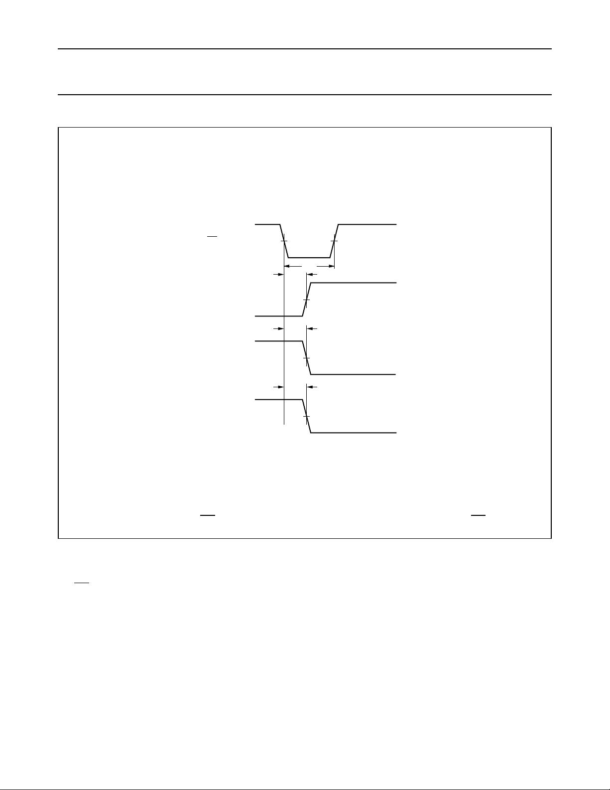
Master reset applied with FIFO full
handbook, halfpage
t
t
M
PLH
PHL
(1)
t
W
(1)
V
M
3
MR INPUT V
DIR OUTPUT
2
1
t
PHL
4
(1)
V
M
5
MGA668
(1) HC : VM= 50%; VI= GND to VCC.
HCT : V
= 1.3 V; VI= GND to 3 V.
M
DOR OUTPUT
Qn OUTPUT
Fig.9 Waveforms showing the MR input to DIR, DOR and Qn output propagation delays and the MR pulse width.
Notes to Fig.9
1. DIR LOW, output ready HIGH; assume FIFO is full
MR pulse LOW; clears FIFO
2.
3. DIR goes HIGH; flag indicates input prepared for valid data
4. DOR goes LOW; flag indicates FIFO empty
5. Qn outputs go LOW (only last bit will be reset).
September 1993 14
Page 15
Philips Semiconductors Product specification
5-Bit x 64-word FIFO register; 3-state 74HC/HCT7404
handbook, full pagewidth
SO INPUT
DOR OUTPUT
Qn OUTPUT
(1) HC : VM= 50%; VI= GND to VCC.
HCT : V
= 1.3 V; VI= GND to 3 V.
M
1st SO pulse 2nd SO pulse 64th SO pulse
1/ f
max
(1)
t
V
PLH
M
t
W
(1)
V
M
2
t
PHL
15
1st word 2nd word 64th word
(1)
V
M
64
73
MGA661
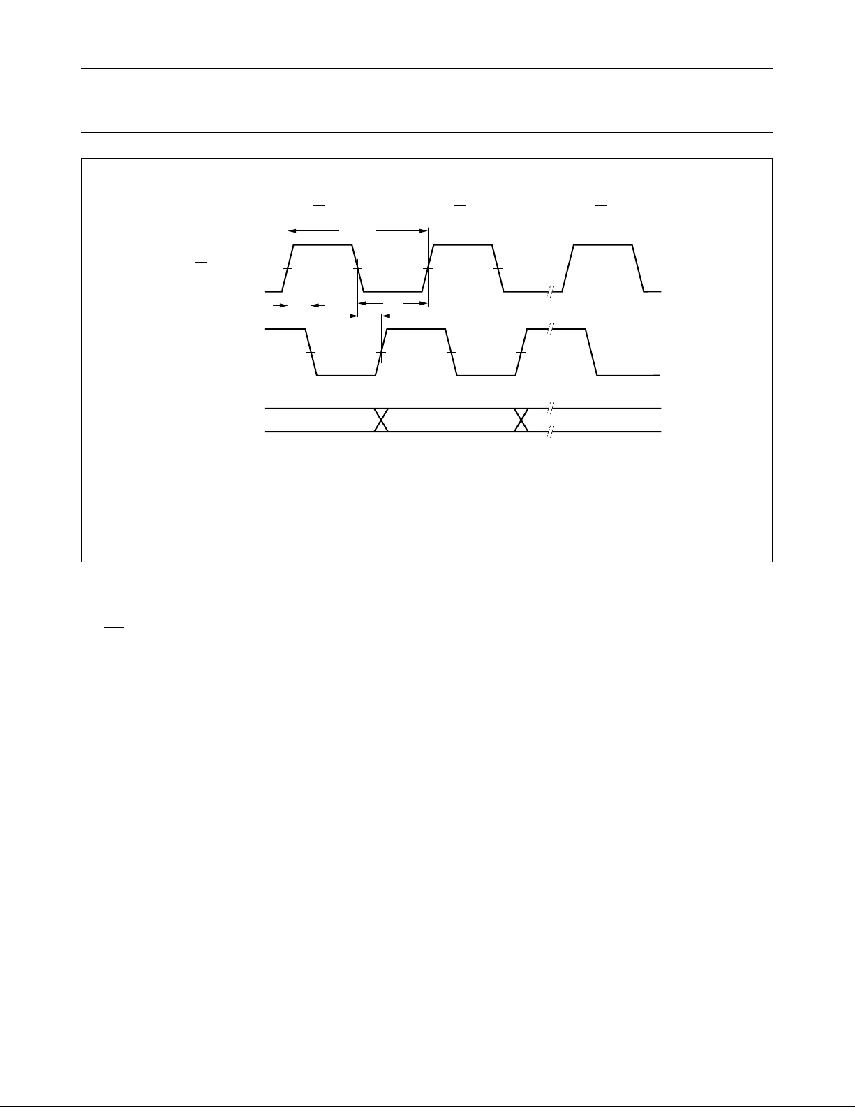
Fig.10 Waveforms showing the SO input to DOR output propagation delay, the SO pulse widths and maximum
pulse frequency.
Notes to Fig.10
1. DOR HIGH; no data transfer in progress, valid data is present at output stage
2. SO set HIGH; results in DOR going LOW
3. DOR goes LOW; output stage “busy”
4. SO set LOW; data in the input stage is unloaded, and new data replaces it as empty location “bubbles-up” to input
stage
5. DOR goes HIGH; transfer process completed, valid data present at output after the specified propagation delay
6. Repeat process to unload the 3rd through to the 64th word from FIFO.
7. DOR remains LOW; FIFO is empty.
September 1993 15
Page 16
Philips Semiconductors Product specification
5-Bit x 64-word FIFO register; 3-state 74HC/HCT7404
With FIFO empty; SO is held HIGH in anticipation
handbook, full pagewidth
(1)
SI INPUT
2
V
M
SO INPUT
DOR OUTPUT
Q
OUTPUT
n
(1) HC : VM= 50%; VI= GND to VCC.
HCT : V
= 1.3 V; VI= GND to 3 V.
M
(1)
1
V
M
t
ripple through
PLH
delay
35
t
W
(1)
V
M
t
PHL
4
t
PLH
6
MGA669
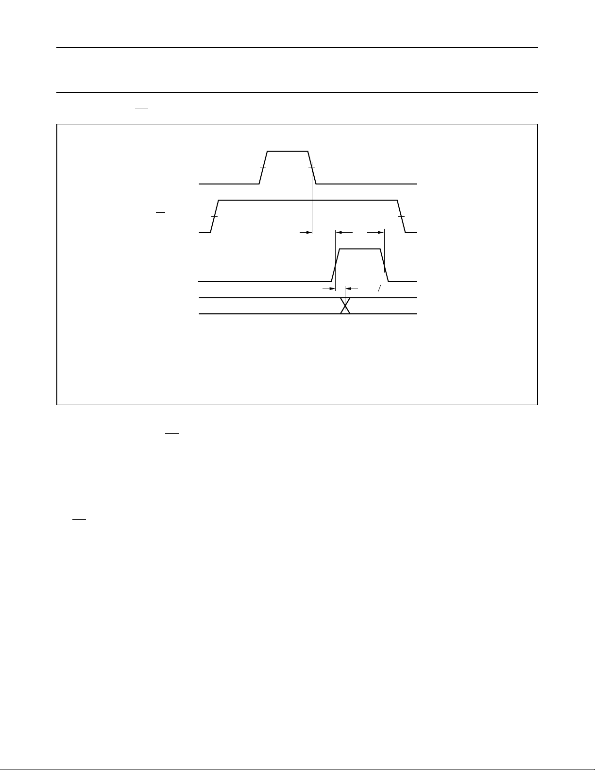
Fig.11 Waveforms showing ripple through delay SI input to DOR output, DOR output pulse width and propagation
delay from the DOR pulse to the Qn output.
Notes to Fig.11
1. FIFO is initially empty, SO is held HIGH
2. SI pulse; loads data into FIFO and initiates ripple through process
3. DOR flag signals the arrival of valid data at the output stage
4. Output transition; data arrives at output stage after the specified propagation delay between the rising edge of the
DOR pulse to the Qn output
5. DOR goes LOW; data shift-out is complete, FIFO is empty again
6. SO set LOW; necessary to complete shift-out process. DOR remains LOW, because FIFO is empty.
September 1993 16
Page 17
Philips Semiconductors Product specification
5-Bit x 64-word FIFO register; 3-state 74HC/HCT7404
Shift-in operation; high-speed burst mode
1/ f
handbook, full pagewidth
SI INPUT
Dn INPUT
DIR OUTPUT
(1)
V
M
max
t
W
MGA662
(1) HC : VM= 50%; VI= GND to VCC.
HCT : V
= 1.3 V; VI= GND to 3 V.
M
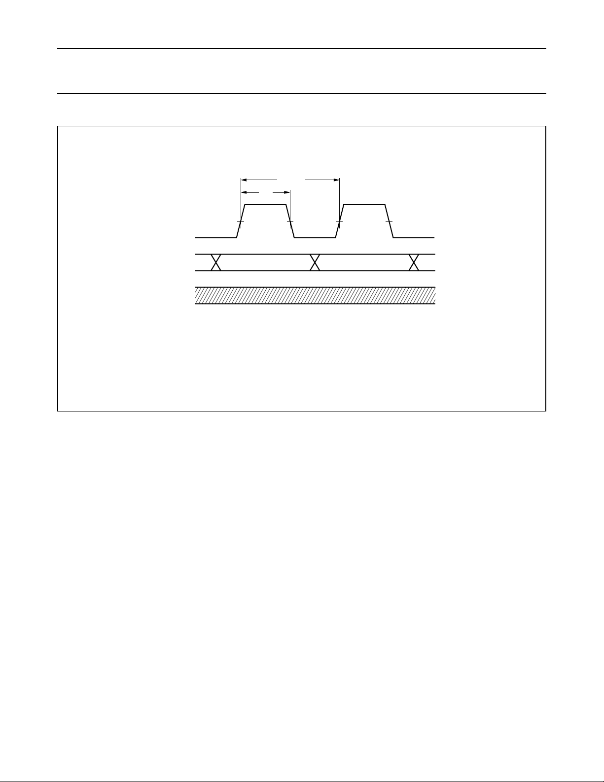
Fig.12 Waveforms showing SI minimum pulse width and maximum pulse frequency, in high-speed shift-in burst
mode.
Note to Fig.12
In the high-speed mode, the burst-in rate is determined by the minimum shift-in HIGH and shift-in LOW specifications.
The DIR status flag is a don't care condition, and a shift-in pulse can be applied regardless of the flag. A SI pulse which
would overflow the storage capacity of the FIFO is ignored.
September 1993 17
Page 18
Philips Semiconductors Product specification
5-Bit x 64-word FIFO register; 3-state 74HC/HCT7404
Shift-out operation; high-speed burst mode
1/ f
handbook, full pagewidth
SO INPUT
Qn OUTPUT
DOR OUTPUT
(1)
V
M
max
t
W
MGA663
(1) HC : VM= 50%; VI= GND to VCC.
HCT : V
= 1.3 V; VI= GND to 3 V.
M
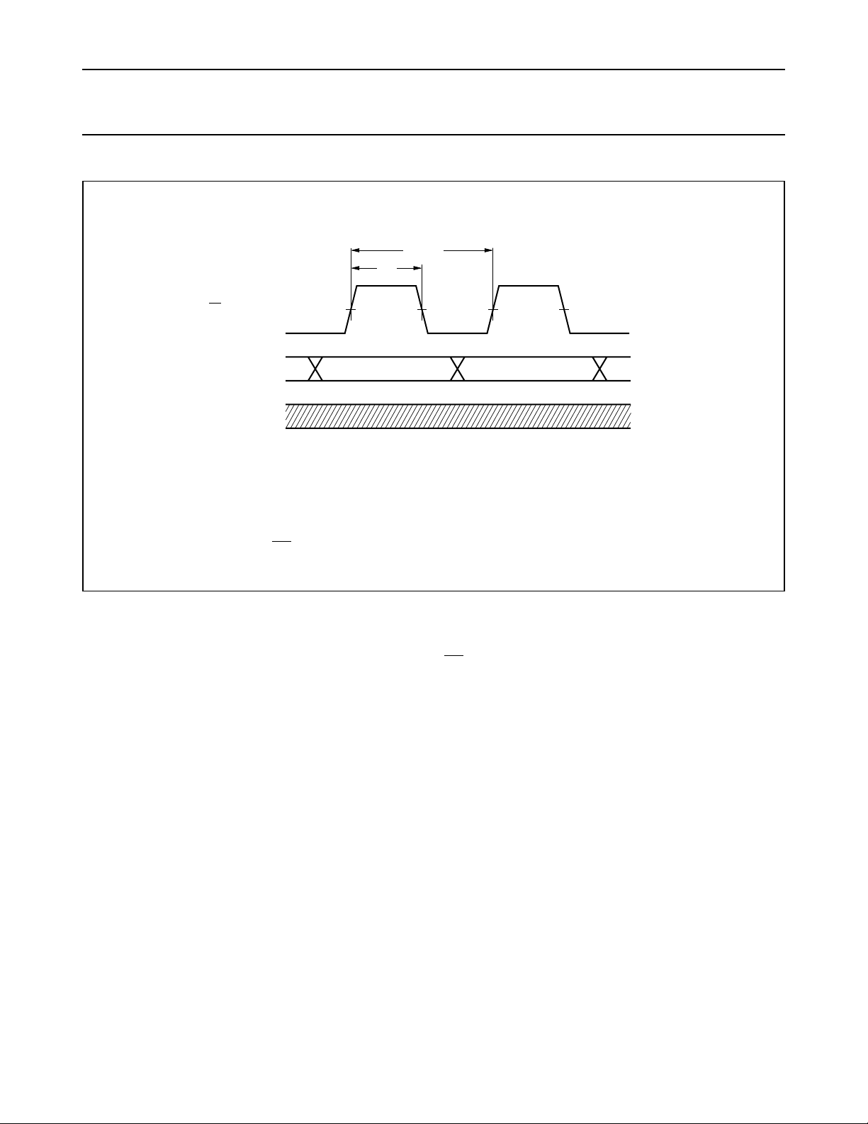
Fig.13 Waveforms showing SO minimum pulse width and maximum pulse frequency, in high-speed shift-out
burst mode.
Note to Fig.13
In the high-speed mode, the burst-out rate is determined by the minimum shift-out HIGH and shift-out LOW
specifications. The DOR flag is a don't care condition and an
SO pulse can be applied without regard to the flag.
September 1993 18
Page 19
Philips Semiconductors Product specification
5-Bit x 64-word FIFO register; 3-state 74HC/HCT7404
handbook, full pagewidth
Dn INPUT
SI INPUT
(1)
V
M
t
su
t
h
(1)
V
M
(1) HC : VM= 50%; VI= GND to VCC.
HCT : V
= 1.3 V; VI= GND to 3 V.
M
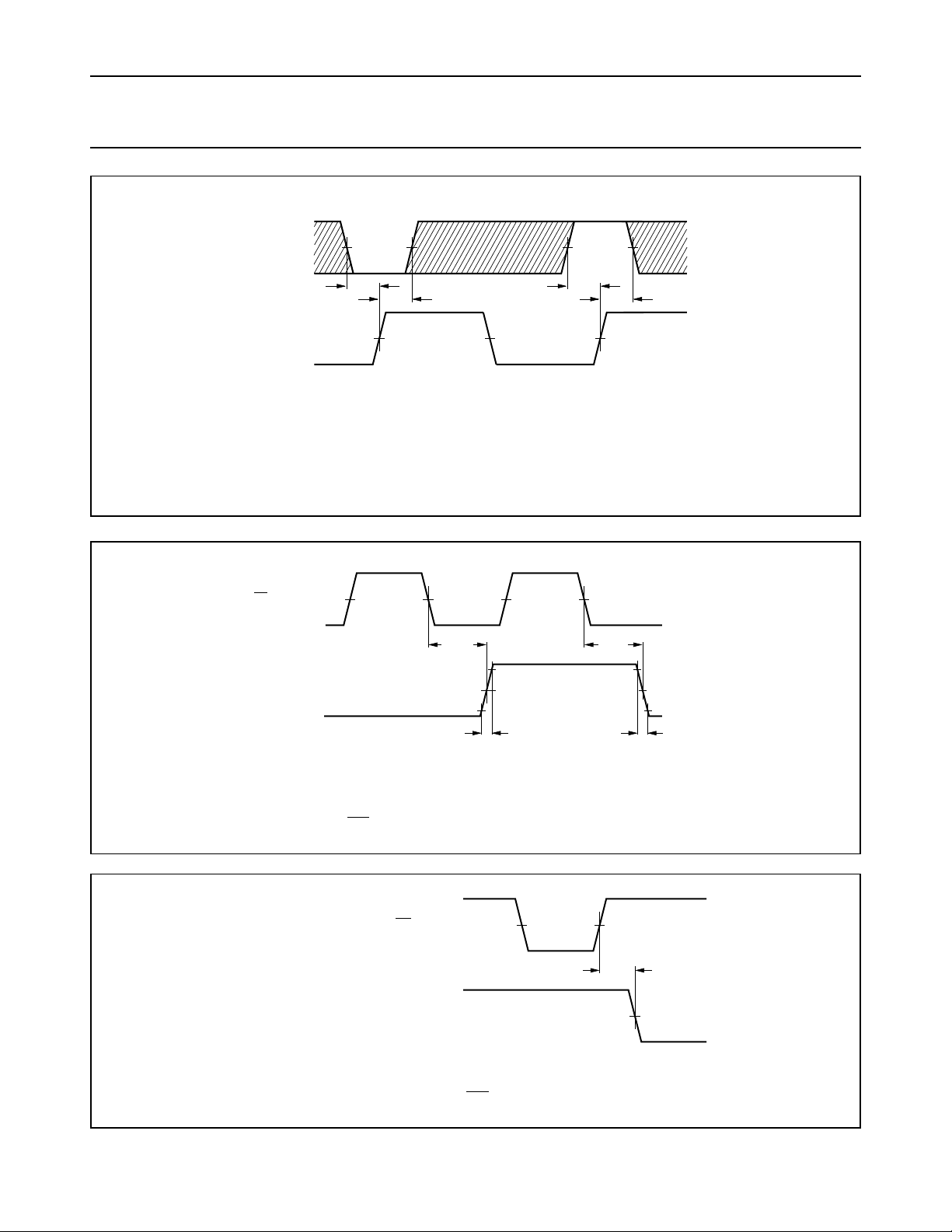
The shaded areas indicate when the input is permitted to change for predictable output performance.
Fig.14 Waveforms showing hold and set-up times for Dn input to SI input.
handbook, full pagewidth
SO INPUT
(1)
V
M
t
PLH
t
su
t
h
MGA657
t
PHL
Qn OUTPUT
MGA664
(1) HC : VM= 50%; VI= GND to VCC.
HCT : V
= 1.3 V; VI= GND to 3 V.
M
Fig.15 Waveforms showing SO input to Qn output propagation delays and output transition time.
(1) HC : VM= 50%; VI= GND to VCC.
HCT : V
= 1.3 V; VI= GND to 3 V.
M
Fig.16 Waveform showing the MR input to SI input removal time.
t
TLH
handbook, halfpage
MR INPUT
SI INPUT
(1)
V
M
t
THL
(1)
V
M
t
rem
(1)
V
M
MGA665
September 1993 19
Page 20
Philips Semiconductors Product specification
5-Bit x 64-word FIFO register; 3-state 74HC/HCT7404
handbook, full pagewidth
OE INPUT
Q OUTPUT
LOW - to - OFF
OFF - to - LOW
Q OUTPUT
HIGH - to - OFF
OFF - to - HIGH
MGA656
(1) HC : VM= 50%; VI= GND to VCC.
HCT : V
= 1.3 V; VI= GND to 3 V.
M
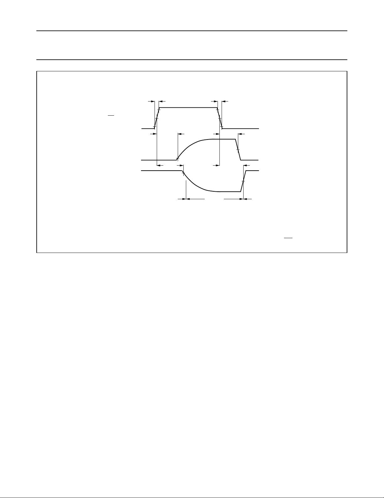
Fig.17 Waveforms showing the 3-state enable and disable times for input OE.
t
r
90 %
(1)
V
10 %
n
n
M
t
PLZ
t
PHZ
outputs
enabled
10 %
90 %
t
outputs
disabled
f
t
PZL
(1)
V
M
t
PZH
(1)
V
M
outputs
enabled
September 1993 20
Page 21
Philips Semiconductors Product specification
5-Bit x 64-word FIFO register; 3-state 74HC/HCT7404
APPLICATION INFORMATION
handbook, full pagewidth
10-bit
data
OE
DIR
MR
10-bit
data
SO
DOR
SI
OE
SI DOR
D
0
D
1
D
7404
2
D
3
D
4
DIR
OE
SI DOR
D
0
D
1
D
7404
2
D
3
D
4
DIR
Q
0
Q
1
Q
2
Q
3
Q
4
SOMR
Q
0
Q
1
Q
2
Q
3
Q
4
SOMR
OE
SI DOR
D
0
D
1
D
7404
2
D
3
D
4
DIR
OE
SI DOR
D
0
D
1
D
7404
2
D
3
D
4
DIR
Q
0
Q
1
Q
2
Q
3
Q
4
SOMR
Q
0
Q
1
Q
2
Q
3
Q
4
SOMR
MGA686
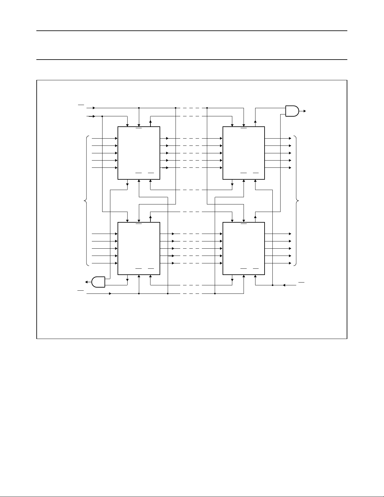
Fig.18 Expanded FIFO (parallel and serial) for increased word length; 10 bits wide × 64 n-bits.
September 1993 21
Page 22
Philips Semiconductors Product specification
5-Bit x 64-word FIFO register; 3-state 74HC/HCT7404
handbook, full pagewidth
DATA INPUT
COMPOSITE
DIR
FLAG
DATA INPUT DATA OUTPUT
SI
MR
5 5
5 5
D
DIR
SI
MR
DIR
SI
MR
D
n
n
7404
7404
Q
DOR
SO
OE
DOR
SO
OE
Q
MGA681
n
n
DATA OUTPUT
COMPOSITE
DOR
FLAG
SO
OE
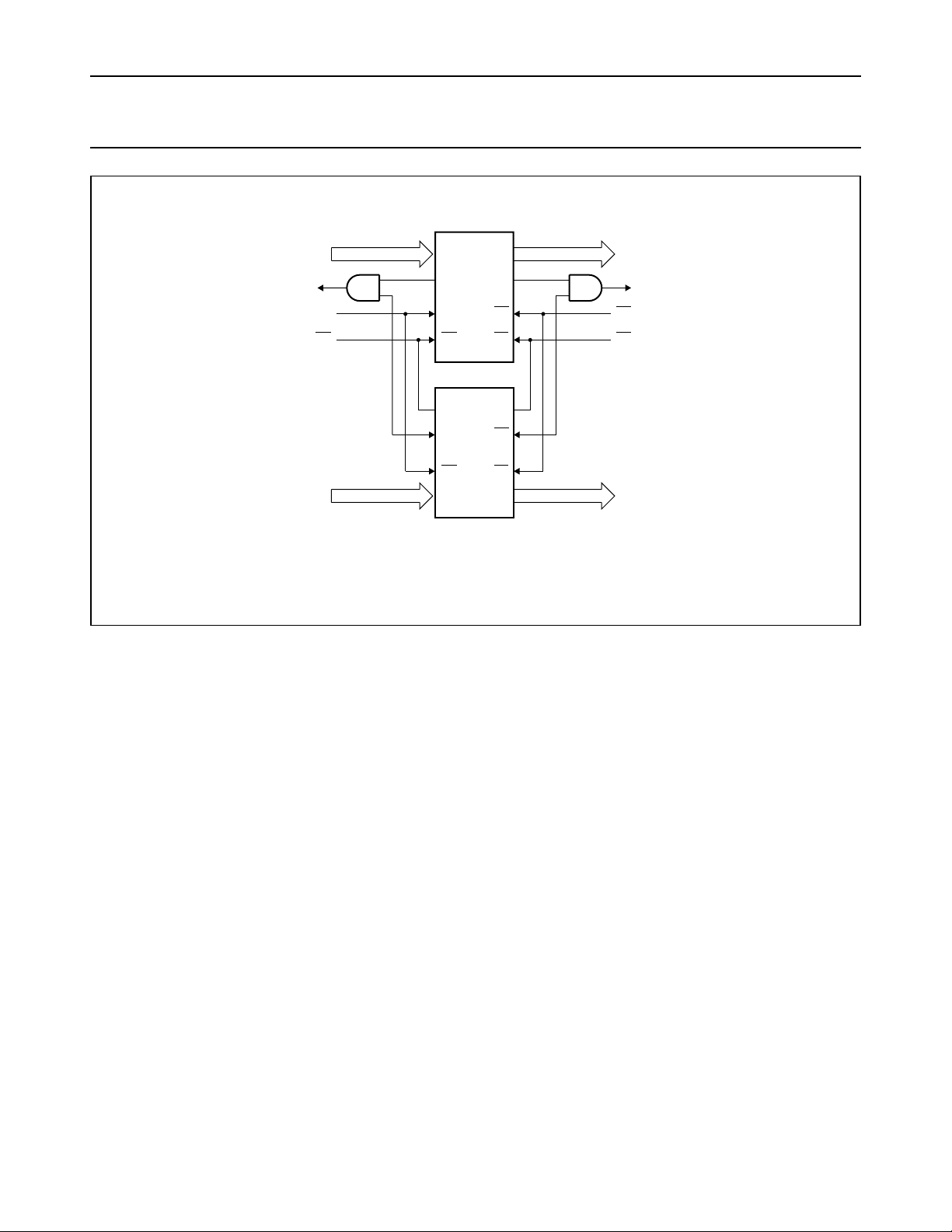
Fig.19 Expanded FIFO for increased word length; 64 words × 10 bits.
Note to Fig.19
The ”7404” is easily expanded to increase word length. Composite DIR and DOR flags are formed with the addition of
an AND gate. The basic operation and timing are identical to a single FIFO, with the exception of an added gate delay
on the flags.
September 1993 22
Page 23
Philips Semiconductors Product specification
5-Bit x 64-word FIFO register; 3-state 74HC/HCT7404
handbook, full pagewidth
composite
DIR
D
5
DIR
DQ
74
CP
Q
DQ
CP
Q
R
SI
MR
SI
MR
DIR
SI
MR
5 5
D
n
n
7404
7404
Q
DOR
SO
OE
DOR
SO
OE
Q
5
n
DQ
74
CP
Q
DQ
CP
SO
OE
n
Q
R
MGA685
composite
DOR
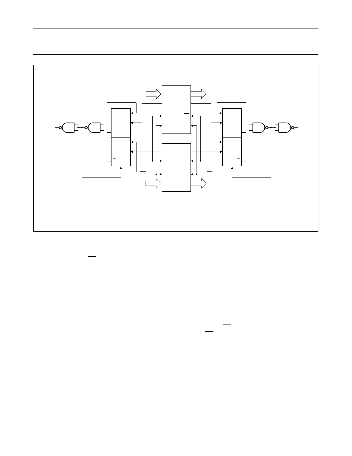
Fig.20 Expanded FIFO for increased word length.
Note to Fig.20
This circuit is only required if the SI input is constantly held HIGH, when the FIFO is empty and the automatic shift-in
cycles are started or if SO output is constantly held HIGH, when the FIFO is full and the automatic shift-out cycles are
started (see Fig.8 and Fig.10).
Expanded format
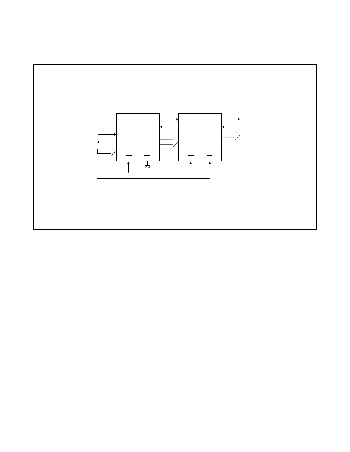
Figure 21 shows two cascaded FIFOs providing a capacity of 128 words x 5 bits. Figure 22 shows the signals on the
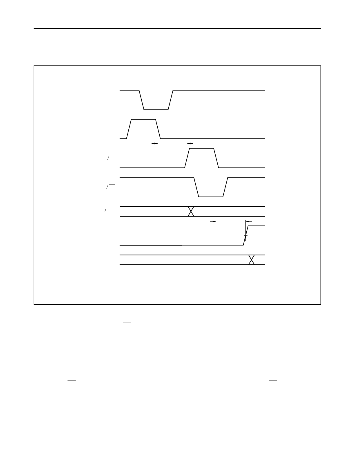
nodes of both FIFOs after the application of a SI pulse, when both FIFOs are initially empty. After a ripple through delay,
data arrives at the output of FIFO
. Due to SOA being HIGH, a DORA pulse is generated. The requirements of SIB and
A
DnB are satisfied by the DORA pulse width and the timing between the rising edge of DORA and QnA. After a second ripple
through delay, data arrives at the output of FIFOB.
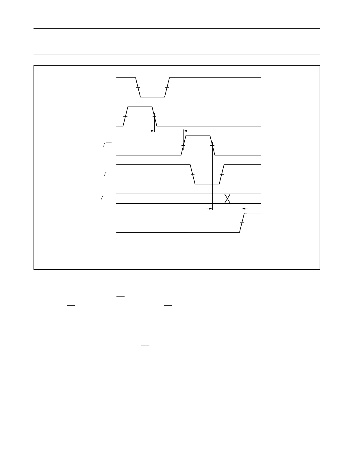
Figure 23 shows the signals on the nodes of both FIFOs after the application of aSOB pulse, when both FIFOs are initially
full. After a bubble-up delay a DIRB pulse is generated, which acts as a SOA pulse for FIFOA. One word is transferred
from the output of FIFOA to the input of FIFOB. The requirements of the SOA pulse for FIFOA is satisfied by the pulse
width of DORB. After a second bubble-up delay an empty space arrives at DnA, at which time DIRA goes HIGH.
Figure 24 shows the waveforms at all external nodes of both FIFOs during a complete shift-in and shift-out sequence.
September 1993 23
Page 24
Philips Semiconductors Product specification
5-Bit x 64-word FIFO register; 3-state 74HC/HCT7404
handbook, full pagewidth
DIR
DATA INPUT
MR
OE
DOR
A
SO
A
SI
SI
7404
A
FIFO A
DIR
A
D
5
nA
MR
OE
Q
nA
SI
B
DIR
B
5
D
nB
MR
7404
FIFO B
DOR
OE
SO
Q
B
B
nB
MGA682
5
DOR
SO
DATA OUTPUT
Fig.21 Cascading for increased word capacity; 128 word × 5 bits.
Note to Fig.21
The “7404” is easily cascaded to increase word capacity without any external circuitry. In cascaded format, all necessary
communications are handled by the FIFOs. Figures 22 and 23 demonstrate the intercommunication timing between
FIFOA and FIFOB. Figure 24 provides an overview of pulses and timing of two cascaded FIFOs, when shifted full and
shifted empty again.
September 1993 24
Page 25
Philips Semiconductors Product specification
5-Bit x 64-word FIFO register; 3-state 74HC/HCT7404
handbook, full pagewidth
DIR
SI
A
DOR
DIR
Q
nA nB
DOR
Q
nB
(1)
A
SI
B
A
SO
1
A
B
D
B
V
M
(1)
V
M
2
ripple through
delay
4
(1)
V
M
(1)
56
V
M
3
ripple through
delay
7
V
(1)
M
MGA666
Fig.22 FIFO to FIFO communication; input timing under empty condition.
Notes to Fig.22
1. FIFOA and FIFOB initially empty, SOA held HIGH in anticipation of data
2. Load one word into FIFOA; SI pulse applied, results in DIR pulse
3. Data-outA/data-inB transition; valid data arrives at FIFOA output stage after a specified delay of the DOR flag,
meeting data input set-up requirements of FIFO
B
4. DORA and SIB pulse HIGH; (ripple through delay after SIA LOW) data is unloaded from FIFOA as a result of the data
output ready pulse, data is shifted into FIFO
B
5. DIRB and SOA go LOW; flag indicates input stage of FIFOB is busy, shift-out of FIFOA is complete
6. DIRB and SOA go HIGH automatically; the input stage of FIFOB is again able to receive data, SO is held HIGH in
anticipation of additional data
7. DORB goes HIGH; (ripple through delay after SIB LOW) valid data is present one propagation delay later at the FIFO
output stage.
September 1993 25
B
Page 26
Philips Semiconductors Product specification
5-Bit x 64-word FIFO register; 3-state 74HC/HCT7404
handbook, full pagewidth
DOR
SO
DIR
DOR
Q
nA nB
DIR
(1)
V
B
B
SO
A
B
SI
1
B
A
D
A
M
(1)
V
M
2
bubble - up
delay
3
(1)
V
M
(1)
4
V
M
5
bubble - up
delay
V
M
MGA667
6
(1)
Fig.23 FIFO to FIFO communication; output timing under full condition.
Notes to Fig.23
1. FIFOA and FIFOB initially full, SIB held HIGH in anticipation of shifting in new data as an empty location bubbles-up
2. Unload one word from FIFOB; SO pulse applied, results in DOR pulse
3. DIRB and SOA pulse HIGH; (bubble-up delay after SOB LOW) data is loaded into FIFOB as a result of the DIR pulse,
data is shifted out of FIFO
A
4. DORA and SIB go LOW; flag indicates the output stage of FIFOA is busy, shift-in to FIFOB is complete
5. DORA and SIB go HIGH; flag indicates valid data is again available at FIFOA output stage, SIB is held HIGH, awaiting
bubble-up of empty location
6. DIRA goes HIGH; (bubble-up delay after SOA LOW) an empty location is present at input stage of FIFOA.
September 1993 26
Page 27
Philips Semiconductors Product specification
5-Bit x 64-word FIFO register; 3-state 74HC/HCT7404
handbook, full pagewidth
SO INPUT
B
DORB OUTPUT
Q OUTPUT
nB
DIRB OUTPUT
DORA OUTPUT
QnA OUTPUT
DIRA OUTPUT
SI INPUT
A
sequence 1 sequence 2 sequence 3 sequence 4 sequence 5 sequence 6
(8)
(3) (4)
(13)
(12)
(1)
(2)
(5)
(9)
(6)
(10)
(7)
(11)
(14)
D INPUT
nA
MR INPUT
MGA687
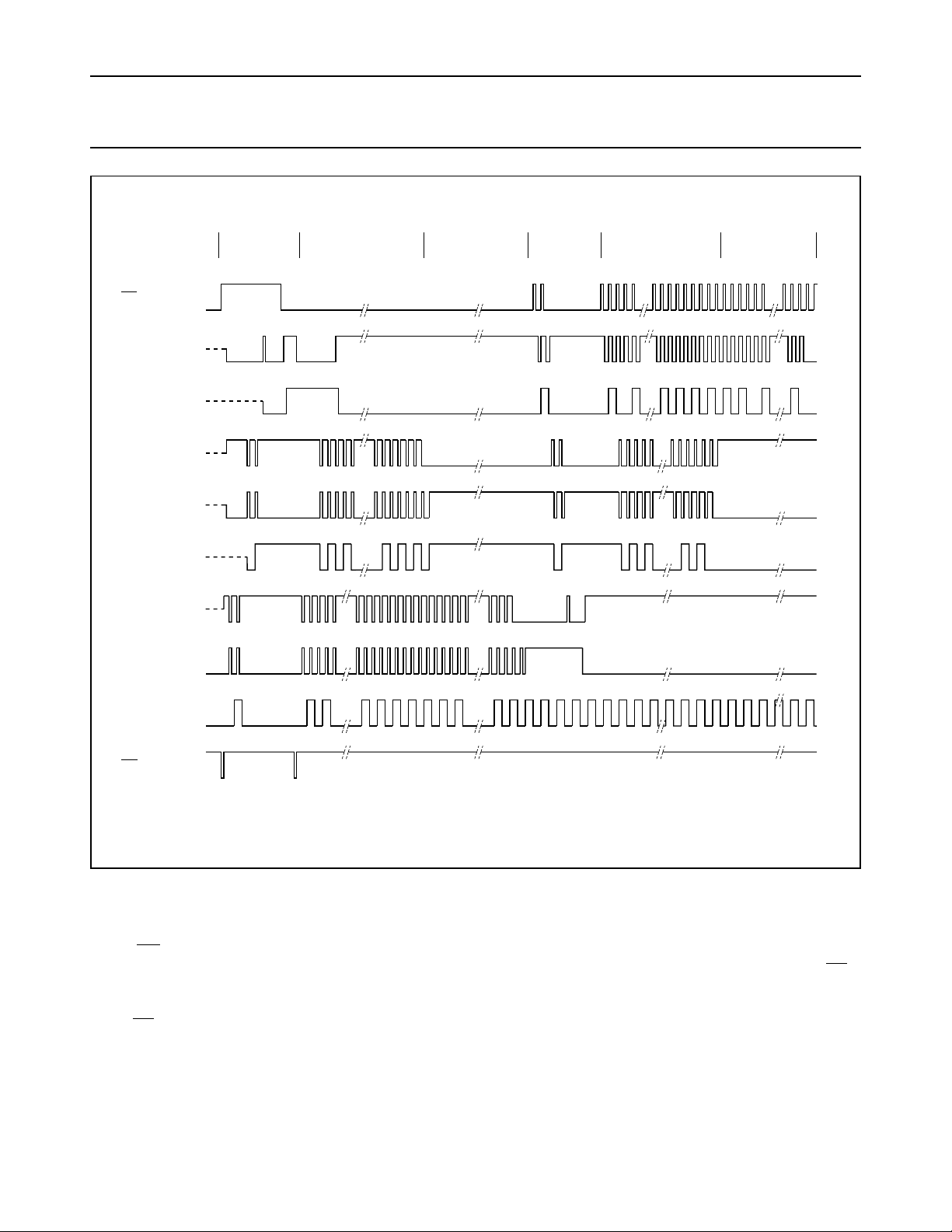
Fig.24 Waveforms showing the functionality and intercommunication between two FIFOs (refer to Fig.19).
Note to Fig.24 Sequence 1 (both FIFOS empty, starting SHIFT-IN process)
After a MR pulse has been applied FIFOA and FIFOB are empty. The DOR flags of FIFOA and FIFOB go LOW due to no
valid data being present at the outputs. The DIR flags are set HIGH due to the FIFOs being ready to accept data. SO
is held HIGH and two SIA pulses are applied (1). These pulses allow two data words to ripple through to the output stage
of FIFOA and to the input stage of FIFOB (2). When data arrives at the output of FIFOB, a DORB pulse is generated (3).
When SOB goes LOW, the first bit is shifted out and a second bit ripples through to the output after which DORB goes
HIGH (4).
B
September 1993 27
Page 28

Philips Semiconductors Product specification
5-Bit x 64-word FIFO register; 3-state 74HC/HCT7404
Sequence 2 (FIFOB runs full)
After the
MR pulse, a series of 64 SI
pulses are applied. When 64 words
are shifted in, DIRB remains LOW due
to FIFOB being full (5). DORA goes
LOW due to FIFOA being empty.
Sequence 3 (FIFO
runs full)
A
When 65 words are shifted in, DOR
remains HIGH due to valid data
remaining at the output of FIFOA. Q
nA
remains HIGH, being the polarity of
the 65th data word (6). After the 128th
SI pulse, DIR remains LOW and both
FIFOs are full (7). Additional pulses
have no effect.
Sequence 4 (both FIFOs full, starting SHIFT-OUT process)
SI
is held HIGH and two SOB pulses
A
are applied (8). These pulses shift out
two words and thus allow two empty
locations to bubble-up to the input
stage of FIFOB, and proceed to FIFO
(9). When the first empty location
arrives at the input of FIFOA, a DIR
A
pulse is generated (10) and a new
word is shifted into FIFOA. SIA is
made LOW and now the second
empty location reaches the input
stage of FIFOA, after which DIR
remains HIGH (11).
Sequence 5 (FIFO
At the start of sequence 5 FIFO
runs empty)
A
A
contains 63 valid words due to two
words being shifted out and one word
being shifted in, in sequence 4. An
additional series of SOB pulses are
applied. After 63 SOB pulses, all
A
words from FIFOA are shifted into
FIFOB. DORA remains LOW (12).
A
Sequence 6 (FIFO
After the next
A
remains HIGH due to the input stage
of FIFOB being empty. After another
runs empty)
B
SOB pulse, DIR
B
63 SOB pulses, DORB remains LOW
due to both FIFOs being empty (14).
AdditionalSOB pulses have no effect.
The last word remains available at the
output Qn.
PACKAGE OUTLINES
See
“74HC/HCT/HCU/HCMOS Logic
Package Outlines”
.
September 1993 28
 Loading...