

Page 1

INTEGRATED CIRCUITS
DATA SH EET
For a complete data sheet, please also download:
•The IC06 74HC/HCT/HCU/HCMOS Logic Family Specifications
•The IC06 74HC/HCT/HCU/HCMOS Logic Package Information
•The IC06 74HC/HCT/HCU/HCMOS Logic Package Outlines
74HC/HCT4510
BCD up/down counter
Product specification
File under Integrated Circuits, IC06
December 1990
Page 2

Philips Semiconductors Product specification
BCD up/down counter 74HC/HCT4510
FEATURES
• Output capability: standard
• ICC category: MSI
parallel load input (PL), four parallel inputs (D0 to D3), four
parallel outputs (Q0 to Q3), an active LOW terminal count
output (TC), and an overriding asynchronous master reset
input (MR).
Information on D0 to D3 is loaded into the counter while PL
GENERAL DESCRIPTION
The 74HC/HCT4510 are high-speed Si-gate CMOS
devices and are pin compatible with the “4510” of the
“4000B” series. They are specified in compliance with
JEDEC standard no. 7A.
The 74HC/HCT4510 are edge-triggered synchronous
up/down BCD counters with a clock input (CP), an
up/down count control input (UP/
DN), an active LOW
is HIGH, independent of all other input conditions except
the MR input, which must be LOW. With PL LOW, the
counter changes on the LOW-to-HIGH transition of CP if
CE is LOW. UP/DN determines the direction of the count,
HIGH for counting up, LOW for counting down. When
counting up,TC is LOW when Q0 and Q3 are HIGH andCE
is LOW. When counting down, TC is LOW when Q0 to Q
and CE are LOW. A HIGH on MR resets the counter (Q0 to
Q3= LOW) independent of all other input conditions.
count enable input (CE), an asynchronous active HIGH
Logic equation for terminal count:
TC = CE . {(UP/DN).Q0.Q3+(UP/DN). Q0.Q1.Q2.Q3}
QUICK REFERENCE DATA
GND = 0 V; T
=25°C; tr=tf= 6 ns
amb
SYMBOL PARAMETER CONDITIONS
t
/ t
PHL
PLH
f
max
C
I
C
PD
propagation delay CP to Q
n
CL= 15 pF; VCC=5 V2123ns
maximum clock frequency 57 58 MHz
input capacitance 3.5 3.5 pF
power dissipation capacitance per package notes 1 and 2 50 53 pF
3
TYPICAL
UNIT
HC HCT
Notes
1. C
is used to determine the dynamic power dissipation (PD in µW):
PD
PD=CPD× V
2
× fi + ∑ (CL× V
CC
2
× fo) where:
CC
fi= input frequency in MHz
fo= output frequency in MHz
∑ (CL× V
2
× fo) = sum of outputs
CC
CL= output load capacitance in pF
VCC= supply voltage in V
2. For HC the condition is VI= GND to VCC. For HCT the condition is VI= GND to VCC− 1.5 V
ORDERING INFORMATION
“74HC/HCT/HCU/HCMOS Logic Package Information”
See
.
December 1990 2
Page 3

Philips Semiconductors Product specification
BCD up/down counter 74HC/HCT4510
PIN DESCRIPTION
PIN NO. SYMBOL NAME AND FUNCTION
1 PL parallel load input (active HIGH)
4, 12, 13, 3 D
5
6, 11, 14, 2 Q
7
8 GND ground (0 V)
9 MR asynchronous master reset input (active HIGH)
10 UP/
15 CP clock input (LOW-to-HIGH, edge-triggered)
16 V
to D
0
3
parallel inputs
CE count enable input (active LOW)
to Q
0
3
parallel outputs
TC terminal count output (active LOW)
DN up/down control input
CC
positive supply voltage
Fig.1 Pin configuration. Fig.2 Logic symbol. Fig.3 IEC logic symbol.
December 1990 3
Page 4

Philips Semiconductors Product specification
BCD up/down counter 74HC/HCT4510
FUNCTION TABLE
Fig.4 Functional diagram.
MR PL UP/
L
L
L
L
H
Notes
1. H = HIGH voltage level
H
L
L
L
X
L = LOW voltage level
X = don’t care
↑ = LOW-to-HIGH clock transition
DN CE CP MODE
X
X
L
H
X
X
X
H
X
L
L
X
↑
↑
X
parallel load
no change
count down
count up
reset
Fig.5 Timing diagram.
December 1990 4
Page 5
Philips Semiconductors Product specification
BCD up/down counter 74HC/HCT4510
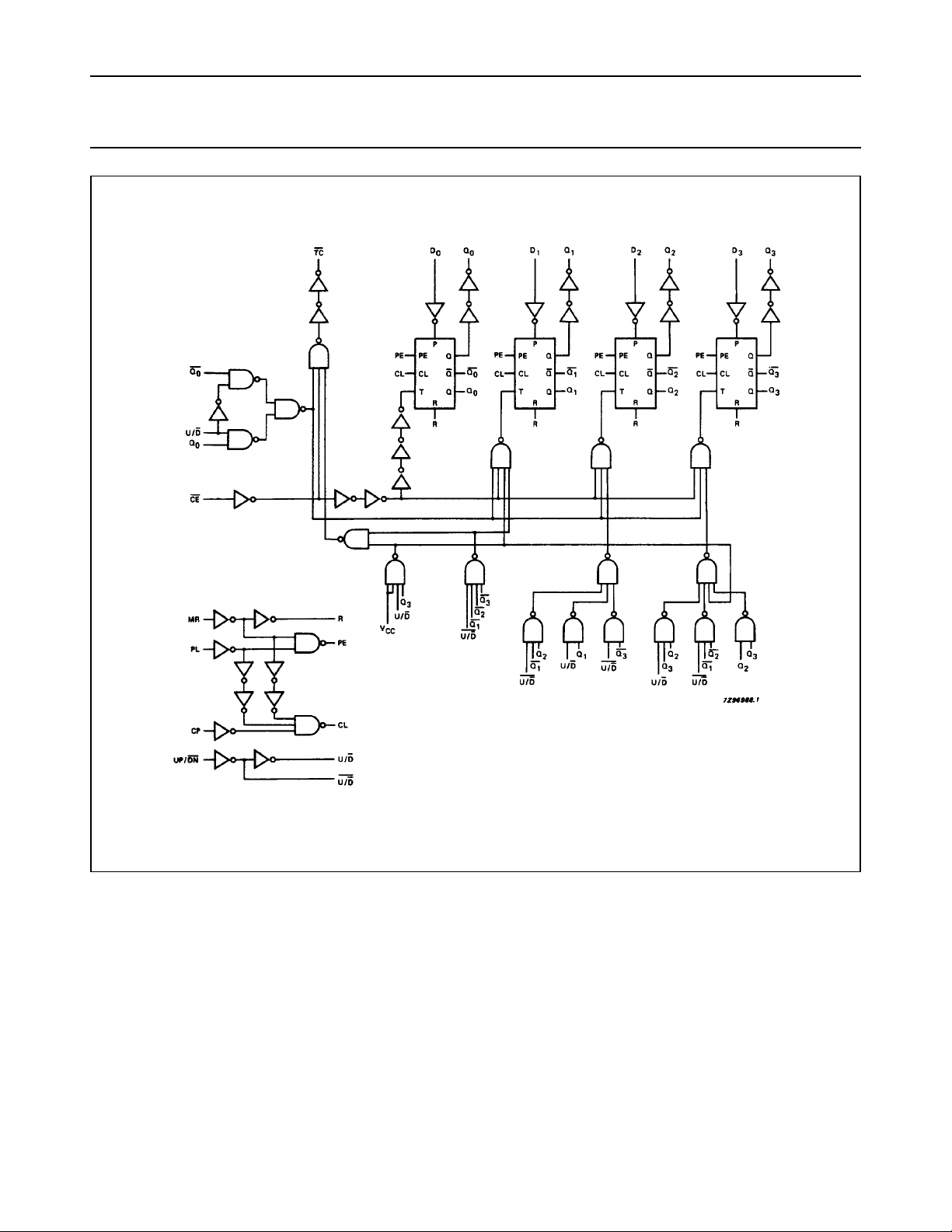
Fig.6 Logic diagram.
December 1990 5
Page 6
Philips Semiconductors Product specification
BCD up/down counter 74HC/HCT4510
DC CHARACTERISTICS FOR 74HC
For the DC characteristics see
“74HC/HCT/HCU/HCMOS Logic Family Specifications”
Output capability: standard
ICC category: MSI
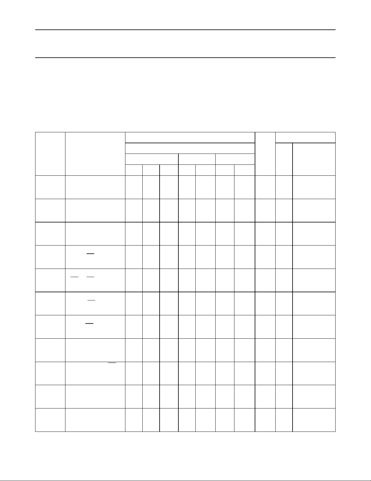
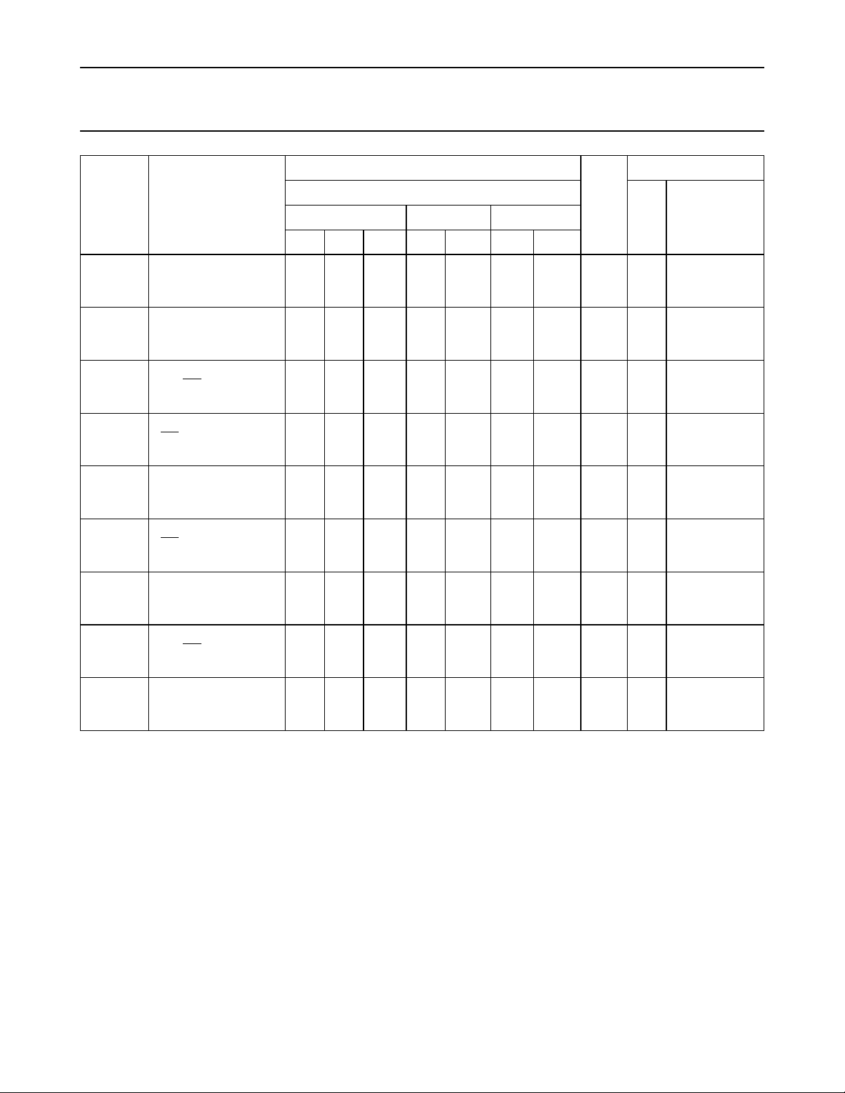
AC CHARACTERISTICS FOR 74HC
GND = 0 V; t
= 6 ns; CL= 50 pF
r=tf
SYMBOL PARAMETER
t
PHL
t
PHL
t
PLH
t
PHL
/ t
/ t
/ t
propagation delay
PLH
CP to Q
propagation delay
MR to Q
propagation delay
PHL
PL to Q
propagation delay
PLH
n
n
n
CP to TC
t
PHL
/ t
propagation delay
PLH
CE to TC
t
PLH
propagation delay
MR to TC
t
PHL
/ t
propagation delay
PLH
PL to TC
t
THL
t
W
/ t
output transition time 19
TLH
pulse width CP, CE
HIGH or LOW
t
W
parallel load pulse
width
HIGH
t
W
master reset pulse
width
HIGH
(°C)
T
amb
74HC
+25 −40 to +85 −40 to +125
min. typ. max. min. max. min. max.
69
80
16
14
80
16
14
100
20
17
25
20
63
23
18
77
28
22
74
27
22
36
13
10
69
25
20
91
33
26
7
6
25
9
7
22
8
7
19
7
6
220
44
37
210
42
36
250
50
43
260
52
44
125
25
21
235
47
40
300
60
51
75
15
13
100
20
17
100
20
17
125
25
21
275
55
47
265
53
45
315
63
54
325
65
55
155
31
26
295
59
50
375
75
64
95
19
16
330
66
56
315
63
54
375
75
64
395
78
66
190
38
32
355
71
60
450
90
77
110
22
19
120
24
20
120
24
20
150
30
26
.
UNIT
ns 2.0
ns 2.0
ns 2.0
ns 2.0
ns 2.0
ns 2.0
ns 2.0
ns 2.0
ns 2.0
ns 2.0
ns 2.0
TEST CONDITIONS
WAVEFORMS
V
CC
(V)
Fig.7
4.5
6.0
Fig.10
4.5
6.0
Fig.9
4.5
6.0
Fig.7
4.5
6.0
Fig.8
4.5
6.0
Fig.10
4.5
6.0
Fig.9
4.5
6.0
Fig.9
4.5
6.0
Fig.7
4.5
6.0
Fig.10
4.5
6.0
Fig.10
4.5
6.0
December 1990 6
Page 7
Philips Semiconductors Product specification
BCD up/down counter 74HC/HCT4510
T
SYMBOL PARAMETER
t
rem
removal time
MR to CP
t
rem
removal time
PL to CP
t
su
set-up time
UP/DN to CP
t
su
set-up time
CE to CP
t
su
set-up time
Dn to PL
t
h
hold time
CE to CP
t
h
hold time
Dn to PL
t
h
hold time
UP/DN to CP
f
max
maximum clock pulse
frequency
(°C)
amb
74HC
+25 −40 to +85 −40 to +125
min. typ. max. min. max. min. max.
80
16
14
80
16
14
100
20
17
100
20
17
100
20
17
5
5
5
3
3
3
0
0
0
6.0
30
35
28
10
8
14
5
4
30
11
9
19
7
6
17
6
5
0
0
0
−6
−2
−2
−19
−7
−6
17
52
62
100
20
17
100
20
17
125
25
21
125
25
21
125
25
21
5
5
5
3
3
3
0
0
0
4.8
24
28
120
24
20
120
24
20
150
30
26
150
30
26
150
30
26
5
5
5
3
3
3
0
0
0
4.0
20
24
UNIT
ns 2.0
ns 2.0
ns 2.0
ns 2.0
ns 2.0
ns 2.0
ns 2.0
ns 2.0
MHz 2.0
TEST CONDITIONS
WAVEFORMS
V
CC
(V)
Fig.10
4.5
6.0
Fig.10
4.5
6.0
Fig.8
4.5
6.0
Fig.8
4.5
6.0
Fig.11
4.5
6.0
Fig.8
4.5
6.0
Fig.11
4.5
6.0
Fig.8
4.5
6.0
Fig.7
4.5
6.0
December 1990 7
Page 8
Philips Semiconductors Product specification
BCD up/down counter 74HC/HCT4510
DC CHARACTERISTICS FOR 74HCT
For the DC characteristics see
“74HC/HCT/HCU/HCMOS Logic Family Specifications”
.
Output capability: standard
ICC category: MSI
Note to HCT types
The value of additional quiescent supply current (∆ICC) for a unit load of 1 is given in the family specifications.
To determine ∆I
per input, multiply this value by the unit load coefficient shown in the table below
CC
INPUT UNIT LOAD COEFFICIENT
D
n
PL, CE
UP/DN
CP
MR
0.75
1.00
1.00
1.25
1.50
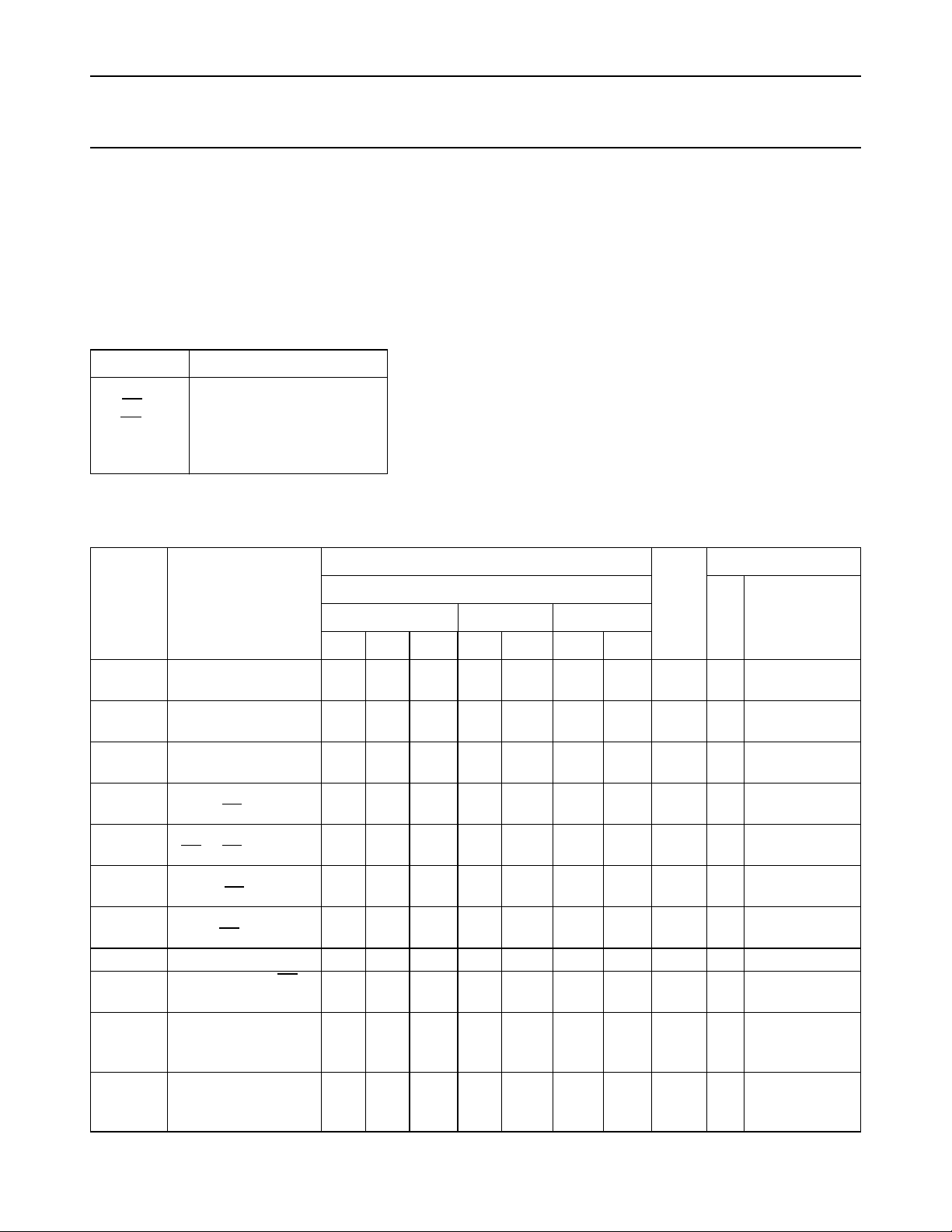
AC CHARACTERISTICS FOR 74HCT
GND = 0 V; t
= 6 ns; CL= 50 pF
r=tf
T
amb
(°C)
TEST CONDITIONS
74HCT
SYMBOL PARAMETER
+25 −40 to +85 −40 to +125
UNIT
V
CC
(V)
WAVEFORMS
min. typ. max. min. max. min. max.
t
PHL
t
PHL
t
PLH
t
PHL
/ t
/ t
/ t
propagation delay
PLH
CP to Q
propagation delay
MR to Q
propagation delay
PHL
PL to Q
propagation delay
PLH
27 50 63 75 ns 4.5 Fig.7
n
25 42 53 63 ns 4.5 Fig.10
n
28 53 66 80 ns 4.5 Fig.9
n
29 58 73 87 ns 4.5 Fig.7
CP to TC
t
PHL
/ t
propagation delay
PLH
17 31 39 47 ns 4.5 Fig.8
CE to TC
t
PLH
propagation delay
31 50 63 75 ns 4.5 Fig.10
MR to TC
t
PHL
/ t
propagation delay
PLH
35 68 85 102 ns 4.5 Fig.10
PL to TC
t
THL
t
W
/ t
output transition time 7 15 19 22 ns 4.5 Fig.9
TLH
pulse width CP, CE
16 9 20 24 ns 4.5 Fig.7
HIGH or LOW
t
W
parallel load pulse
16 6 20 24 ns 4.5 Fig.10
width
HIGH
t
W
master reset pulse
20 4 25 30 ns 4.5 Fig.10
width
HIGH
December 1990 8
Page 9
Philips Semiconductors Product specification
BCD up/down counter 74HC/HCT4510
T
SYMBOL PARAMETER
t
rem
removal time
MR to CP
t
rem
removal time
PL to CP
t
su
set-up time
UP/DN to CP
t
su
set-up time
CE to CP
t
su
set-up time
Dn to PL
t
h
hold time
CE to CP
t
h
hold time
Dn to PL
t
h
hold time
UP/DN to CP
f
max
maximum clock pulse
frequency
(°C)
amb
74HCT
UNIT
+25 −40 to +85 −40 to +125
min. typ. max. min. max. min. max.
23 13 29 35 ns 4.5 Fig.10
17 10 21 26 ns 4.5 Fig.10
20 12 25 30 ns 4.5 Fig.8
20 6 25 30 ns 4.5 Fig.8
20 6 25 30 ns 4.5 Fig.11
5 0 5 5 ns 4.5 Fig.8
5 0 5 5 ns 4.5 Fig.11
0 −5 0 0 ns 4.5 Fig.8
30 53 24 20 MHz 4.5 Fig.7
TEST CONDITIONS
WAVEFORMS
V
CC
(V)
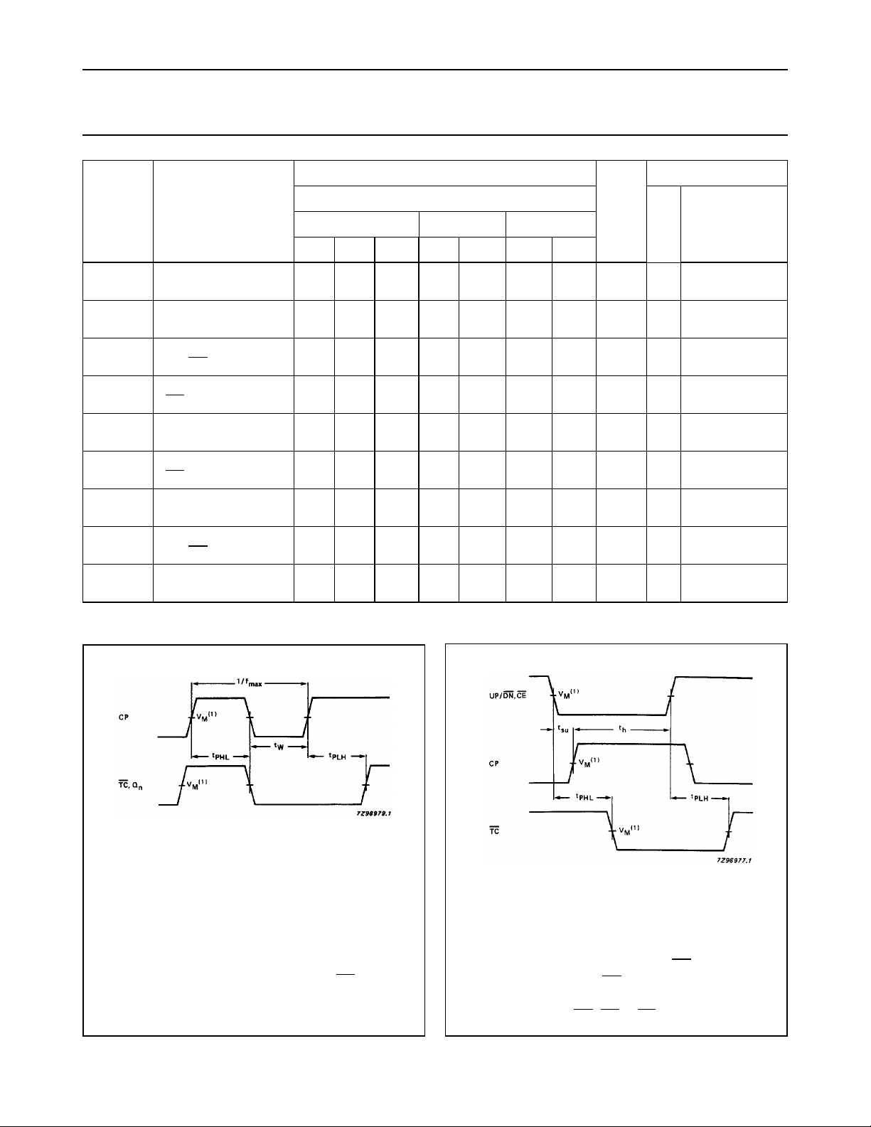
AC WAVEFORMS
(1) HC : VM= 50%; VI= GND to VCC.
HCT: V
= 1.3 V; VI= GND to 3 V.
M
Fig.7 Waveforms showing the clock (CP) to
output (Qn) and terminal count (TC)
propagation delays, the clock pulse width
and the maximum clock pulse frequency.
(1) HC : VM= 50%; VI= GND to VCC.
= 1.3 V; VI= GND to 3 V.
HCT: V
M
Fig.8 Waveforms showing the set-up and hold
times from count enable (CE) and
up/down (UP/DN) control inputs to the
clock pulse (CP), the propagation delays
from UP/DN, CE to TC.
December 1990 9
Page 10
Philips Semiconductors Product specification
BCD up/down counter 74HC/HCT4510
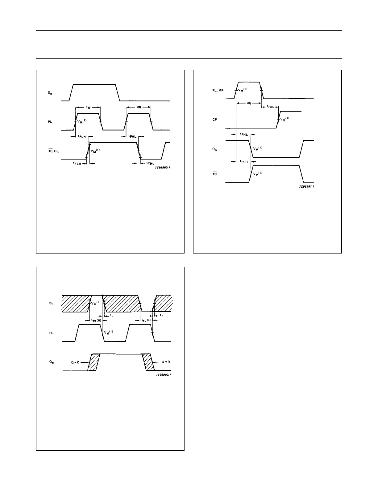
(1) HC : VM= 50%; VI= GND to VCC.
= 1.3 V; VI= GND to 3 V.
HCT: V
M
Fig.9 Waveforms showing the preset enable
pulse width, preset enable to output
delays and output transition times.
(1) HC : VM= 50%; VI= GND to VCC.
= 1.3 V; VI= GND to 3 V.
HCT: V
M
Fig.10 Waveforms showing the master reset pulse,
master reset to terminal count and Qn delay
and master reset to clock removal time.
(1) HC : VM= 50%; VI= GND to VCC.
HCT: V
= 1.3 V; VI= GND to 3 V.
M
Fig.11 Waveforms showing the data set-up and
hold times to parallel load (PL).
December 1990 10
Page 11
Philips Semiconductors Product specification
BCD up/down counter 74HC/HCT4510
APPLICATION INFORMATION
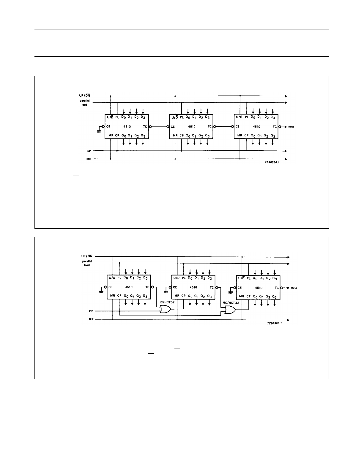
Terminal count (TC) lines at the 2nd, 3rd, etc. stages may have a negative-going
glitch pulse resulting from differential delays of different 4510s. These
negative-going glitches do not affect proper 4510 operation. However, if the
terminal count signals are used to trigger other edge sensitive logic devices, such
as flip-flops or counters, the terminal count signals should be gated with the clock
signal using a 2-input OR gate such as HC/HCT32.
Fig.12 Cascading counter packages (parallel clocking).
Ripple clocking mode: the UP/DN control can be changed at any count. The only
restriction on changing the UP/
stage must be “HIGH”. For cascading counters operating in a fixed up-count or
down-count mode, the OR gates are not required between stages and
connected directly to the CP input of the next stage with
DN control is that the clock input to the first counting
TC is
CE grounded.
Fig.13 Cascading counter packages (ripple clocking).
December 1990 11
Page 12
Philips Semiconductors Product specification
BCD up/down counter 74HC/HCT4510
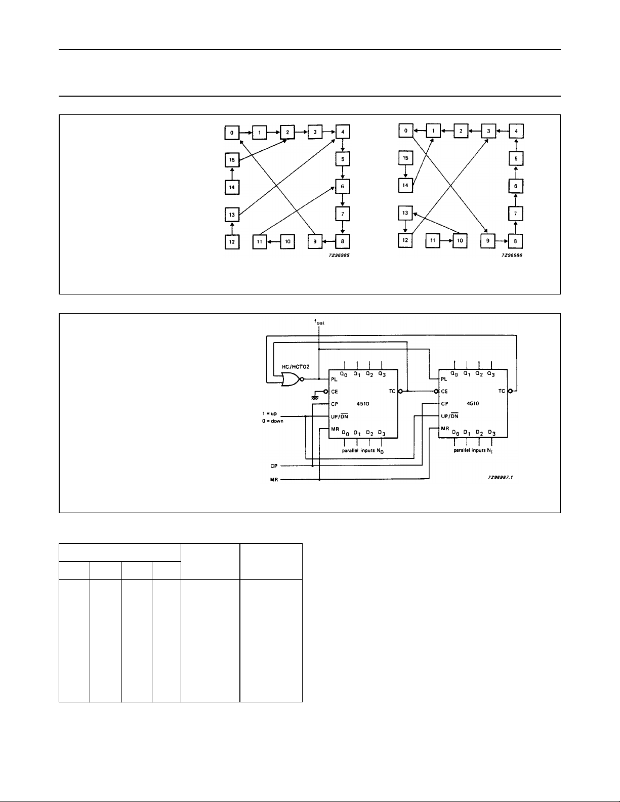
Count-up mode: illegal states in
BCD counters corrected in one count.
Count-down mode: illegal states in
BCD counters corrected in one or
two counts.
Count-up mode. Count-down mode.
Fig.14 State diagram.
Use the following formulae to calculate N
i
N
total
=
f
------------- -
out
N
Formulae are only applicable if legal data is
provided to the parallel inputs.
×()
N
i
+=
0
10 N
π
1
f
in
total
parallel inputs
D
D
3
0
0
0
0
0
0
0
0
1
1
D
2
0
0
0
0
1
1
1
1
0
0
D
1
0
0
0
0
1
1
0
1
1
0
0
0
1
1
0
1
1
0
0
0
1
:
total
Fig.15 Programmable cascaded frequency divider.
PACKAGE OUTLINES
See
count-upncount-down
“74HC/HCT/HCU/HCMOS Logic Package Outlines”
n
9
8
7
6
5
4
3
2
1
(1)
(1)
1
2
3
4
5
6
7
8
9
.
Note
1. no count; f
is HIGH.
out
December 1990 12
 Loading...