

Page 1

INTEGRATED CIRCUITS
74F777
Triple bidirectional latched bus
transceiver (3-State + open collector)
Product specification
IC15 Data Handbook
1992 May 19
Page 2

Philips Semiconductors Product specification
Triple bidirectional latched bus transceiver (3–State +
Open Collector)
FEA TURES
•Latching transceiver
•High drive Open Collector output current with minimum output
swing
•Compatible with Test Mode (TM) bus specification
•Controlled output ramp
•Multiple package options
•Industrial temperature range available (–40°C to +85°C)
DESCRIPTION
The 74F777 is a triple bidirectional latched bus transceiver and is
intended to provide the electrical interface to a high performance
wired–OR bus. This bus has a loaded characteristics impedance
ORDERING INFORMATION
DESCRIPTION COMMERCIAL RANGE INDUSTRIAL RANGE PKG DWG #
VCC = 5V ±10%, T
20–pin plastic DIP (300 mil) N74F777N I74F777N SOT146-1
20–pin PLCC N74F777A I74F777A SOT380-1
= 0°C to +70°C
amb
range of 20 to 50 ohms and is terminated on each end with a 30 to
40 ohm resistor.
The 74F777 is a triple bidirectional transceiver with Open Collector
B and 3–State A port output drivers. A latch function is provided for
the A port signals. The B port output driver is designed to sink
100mA from 2 volts to minimize crosstalk and ringing on the bus.
A separate output threshold clamp voltage (V
prevent the A port output High level from exceeding future high
density processor supply voltage levels. For 5 volt systems, V
simply tied to V
TYPE TYPICAL
74F777 7.0ns 45mA
ORDER CODE
CC.
PROPAGATION DELAY
VCC = 5V ±10%,
T
= –40°C to +85°C
amb
TYPICAL SUPPL Y CUR-
74F777
) is provided to
X
RENT( TOTAL)
is
X
INPUT AND OUTPUT LOADING AND FAN OUT TABLE
PINS DESCRIPTION 74F (U.L.)
A0 – A2 PNP latched inputs 3.5/0.1 17 70µA/70µA
B0 – B2 Data inputs with threshold circuitry 5.0/0.167
OEA0 – OEA2 A output enable inputs (active–High) 1.0/0.033
OEB0 – OEB2 B output enable inputs (active–Low) 1.0/0.033
LE0 – LE2 Latch enable inputs (active–Low) 1.0/0.033
A0 – A2 3–State outputs 150/40 3mA/24mA
B0 – B2 Open Collector outputs OC/166.7 OC/100mA
Note to input and output loading and fan out table
One (1.0) FAST unit load is defined as: 20µA in the High state and 0.6mA in the Low state.
OC = Open Collector.
HIGH/LOW
LOAD VALUE
HIGH/LOW
100µA/100µA
20µA/20µA
20µA/20µA
20µA/20µA
May 19, 1992 853–1645 06772
2
Page 3
Philips Semiconductors Product specification
Triple bidirectional latched bus transceiver (3–State +
Open Collector)
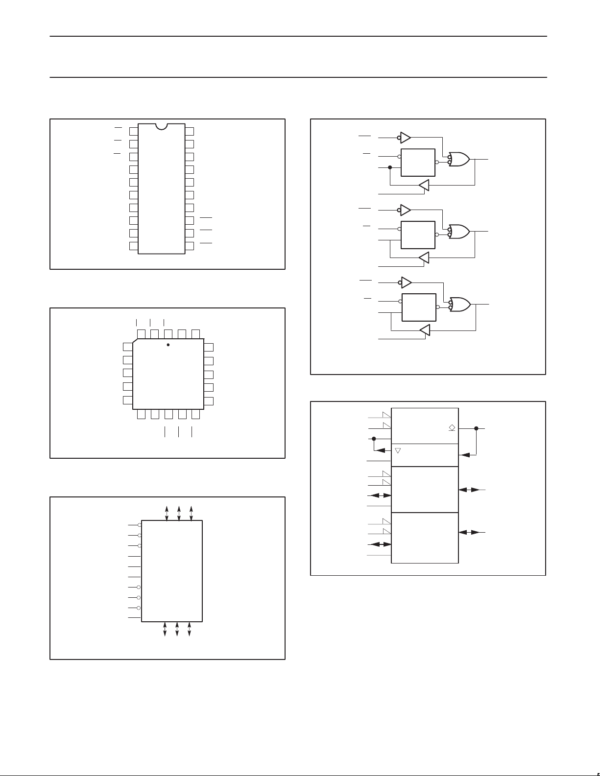
PIN CONFIGURATION
LE
0
1
1
LE
2
LE2
3
OEA0
4
A0
5
OEA1
6
A1
7
OEA2
8
A2
9
10 11
GND
PIN CONFIGURA TION PLCC
LE1
LE0
LE2
3212019
4
OEA0
5
A0
OEA1
OEA2
6
7
A1
8
PLCC
A2
GND
OEB2
LOGIC SYMBOL
5 7 9
20
19
18
17
16
15
14
13
12
SF00432
Vcc
131211109
OEB1
V
CC
V
X
GND
B0
B1
B2
GND
OEB
OEB
OEB
Vx
18
17
16
15
14
OEB0
SF00433
0
1
2
GND
B0
B1
B2
GND
LOGIC DIAGRAM
= Pin 20, VX = Pin 19,
V
CC
GND = Pin 10, 14, 18
IEC/IEEE SYMBOL
OEB
LE0
A0
OEA0
OEB
LE1
A1
OEA1
OEB
LE2
A2
OEA2
74F777
13
0
1
LE
5
4
12
1
2
7
6
11
2
3
9
8
13
EN
1
C1
5
4
EN
12
2
7
6
Q
Data
LE
Q
Data
LE
Q
Data
ID
17
16
15
SF00436
17
16
B0
B1
B2
V
= Pin 20, V
CC
GND = Pin 10, 14, 18
May 19, 1992
13
12
11 OEB2
19
= Pin 19,
X
LE0
LE1
LE2
OEA0
OEA1
OEA2
OEB0
OEB1
V
X
A0 A1 A2
B0 B1 B2
17 16 15
SF00434
1
2
3
4
6
8
11
3
9
8
15
SF00435
3
Page 4
Philips Semiconductors Product specification
Triple bidirectional latched bus transceiver (3–State +
Open Collector)
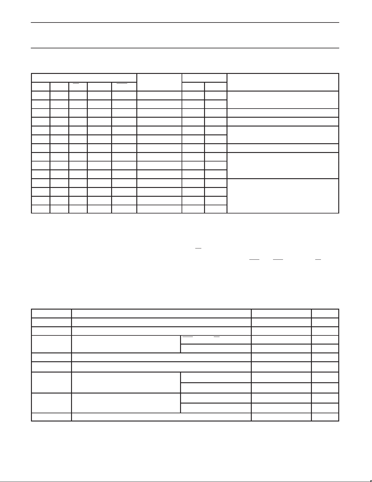
FUNCTION TABLE
INPUTS LATCH OUTPUTS OPERATING MODE
An Bn* LEn OEAn OEBn STATE An Bn
H X L L L H Z H** A 3-State, data from A to B
L X L L L L Z L
X X H L L Qn Z Qn A 3-State, latched data to B
– – L H L (1) (1) (1) Feedback: A to B, B to A
– H H H L H (2) H Z(2) Preconditioned latch enabling
– L H H L H (2) L Z(2) data transfer from B to A
– – H H L Qn Qn Qn Latch state to A and B
H X L L H H Z Z
L X L L H L Z Z B and A 3–State
X X H L H Qn Z Z
– H L H H H H Z
– L L H H L L Z B 3-State, data from B to A
– H H H H Qn H Z
– L H H H Qn
Notes to function table
H = High voltage level
L = Low voltage level
X = Don’t care
– = Input not externally driven
Z = High impedance (off) state
Q
= High or Low voltage level one setup time prior to the Low–to–High LE transition.
n
(1) = Condition will cause a feedback loop path: A to B and B to A.
(2) = The latch must be preconditioned such that B inputs may assume a High or Low level while OEB
* =Precaution should be taken to insure the B inputs do not float. If they do they are equal to Low state.
B
n
H**= Goes to level of pull-up voltage.
Each latch is independent. The latches may be run in any combination of modes.
Qn
L Z
0 and OEB1 are Low and LE is High.
74F777
ABSOLUTE MAXIMUM RATINGS
(Operation beyond the limit set forth in this table may impair the useful life of the device. Unless otherwise noted these limits are over the
operating free air temperature range.)
SYMBOL PARAMETER RATING UNIT
V
V
V
I
IN
V
I
OUT
T
T
CC
X
IN
OUT
amb
stg
Supply voltage –0.5 to +7.0 V
Threshold control –0.5 to +7.0 V
Input voltage OEBn, OEAn, LEn –0.5 to +7.0 V
A0 – A2, B0 – B2 –0.5 to +5.5 V
Input current –30 to +5 mA
Voltage applied to output in High output state –0.5 to V
Current applied to output in A0 – A2 48 mA
Low output state B0 – B2 200 mA
Operating free air Commercial range 0 to +70
temperature range Industrial range –40 to +85
Storage temperature range –65 to +150
CC
V
°C
°C
°C
May 19, 1992
4
Page 5
Philips Semiconductors Product specification
Triple bidirectional latched bus transceiver (3–State +
Open Collector)
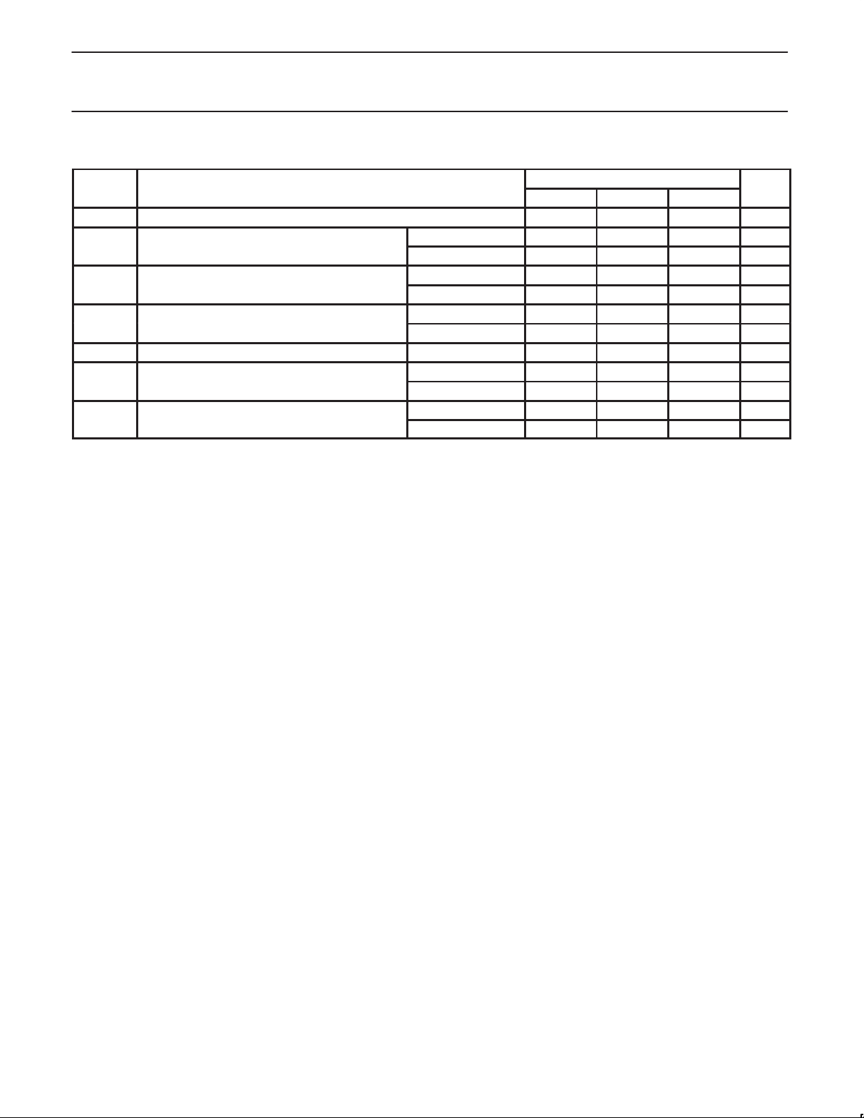
RECOMMENDED OPERATING CONDITIONS
SYMBOL
V
CC
V
IH
V
IL
I
Ik
I
OH
I
OL
T
amb
Supply voltage
High–level input voltage
Low–level input voltage
Input clamp current
High–level output current
Low–level output current A0 – A2
Operating free–air temperature range Commercial range 0 +70
PARAMETER
Except B0 – B2 2.0 V
B0 – B2 1.6 V
Except B0 – B2 0.8 V
B0 – B2 1.43 V
Except A0 – A2 –18 mA
A0 – A2
Except A0 – A2 –3 mA
B0 – B2
Industrial range –40 +85
74F777
LIMITS UNIT
MIN NOM MAX
4.5 5.0 5.5 V
–40 mA
24 mA
100 mA
°C
°C
May 19, 1992
5
Page 6
Philips Semiconductors Product specification
Triple bidirectional latched bus transceiver (3–State +
Open Collector)
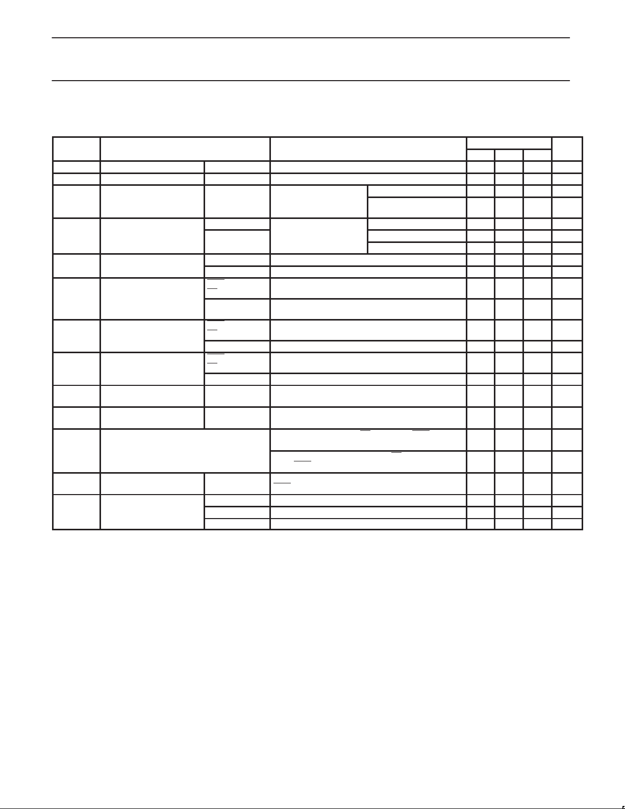
DC ELECTRICAL CHARACTERISTICS
(Over recommended operating free-air temperature range unless otherwise noted.)
SYMBOL
I
OH
I
OFF
V
V
V
I
I
I
IH
I
IL
I
OZH
I
OZL
I
X
I
OS
I
CC
OH
OL
IK
High–level output current B0 – B2 VCC = MAX, VIL = MAX, VIH = MIN, VOH = 2.1V 100 µA
Power–off output current B0 – B2 VCC = 0.0V, VIL = MAX, VIH = MIN, VOH = 2.1V 100 µA
High-level output voltage A0 – A2
Low-level output voltage B0 – B2 VIL = MAX, I
Input clamp voltage A0 – A2 VCC = MIN, II = I
Input current at
maximum input voltage
High–level input current
Low–level input current
Off–state output current,
+ I
IH
High level voltage applied
Off–state output current,
+ I
IL
Low level voltage applied
High level control current
Short circuit output
current
Supply current (total) I
Notes to DC electrical characteristics
1. For conditions shown as MIN or MAX, use the appropriate value specified under recommended operating conditions for the applicable type.
Unless otherwise specified, V
2. All typical values are at V
3. Not more than one output should be shorted at a time. For testing I
techniques are preferable in order to minimize internal heating and more accurately reflect operational values. Otherwise, prolonged shorting
of a high output may raise the chip temperature well above normal and thereby cause invalid readings in other parameter tests. In any
sequence of parameter tests, I
4. Due to test equipment limitations, actual test conditions are for V
PARAMETER TEST LIMITS UNIT
1
= –3mA, VX =V
OH
I
= –4mA, VX = 3.13V
OH
and 3.47V
= 20mA, VX = V
OL
= 100mA 1.15 V
OL
= 4mA 0.40 V
OL
CC
MIN TYP2MAX
2.5 V
2.5 V
cc
4
VIL = MAX,
VIH = MIN
VCC = MIN, I
4
A0 – A2
VCC = MIN, I
VIH = MIN I
Except A0 – A2 VCC = MIN, II = I
OEBn, OEAn,
LEn
VCC = MAX, VI = 7.0V
CONDITIONS
IK
IK
A0 – A2,
B0 – B2
OEBn, OEAn,
LEn
VCC = MAX, VI = 5.5V 1 mA
VCC = MAX, VI = 2.7V, Bn – An = 0V
B0 – B2 VCC = MAX, VI = 2.1V 100 µA
OEBn, OEAn
LEn
,
VCC = MAX, VI = 0.5V
B0 – B2 VCC = MAX, VI = 0.3V –100 µA
A0 – A2 VCC = MAX, V
= 2.7V 70
O
A0 – A2 VCC = MAX, VI = 0.5V –70
VCC = MAX, V
A0 – A2 = 2.7V, B0 – B2 = 2.0V,
VCC = MAX, V
2.7V, OEBn = A0 – A2 = 2.7V, B0 – B2 = 2.0V
3
=VCC for all test condition.
X
= 5V, T
CC
OS
A0 – A2 only
I
CCH
CCL
I
CCZ
= 25°C.
amb
tests should be performed last.
VCC = MAX, Bn = 1.8V, OEAn = 2.0V,
OEBn = 2.7V
VCC = MAX 40 60 mA
VCC = MAX, VIL = 0.5V 55 80 mA
VCC = MAX, VIL = 0.5V 45 67 mA
IH
= VCC, LE = OEAn = OEBn = 2.7V ,
X
= 3.13 & 3.47V , LE = OEAn =
X
–100 100 µA
–10 10 µA
-60 -150 mA
, the use of high-speed test apparatus and/or sample-and-hold
OS
=1.8v and VIL = 1.3V.
74F777
CC
X
0.50 V
-0.5 V
-1.2 V
100 µA
20 µA
–20 µA
V
V
µA
µA
May 19, 1992
6
Page 7
Philips Semiconductors Product specification
Triple bidirectional latched bus transceiver (3–State +
Open Collector)
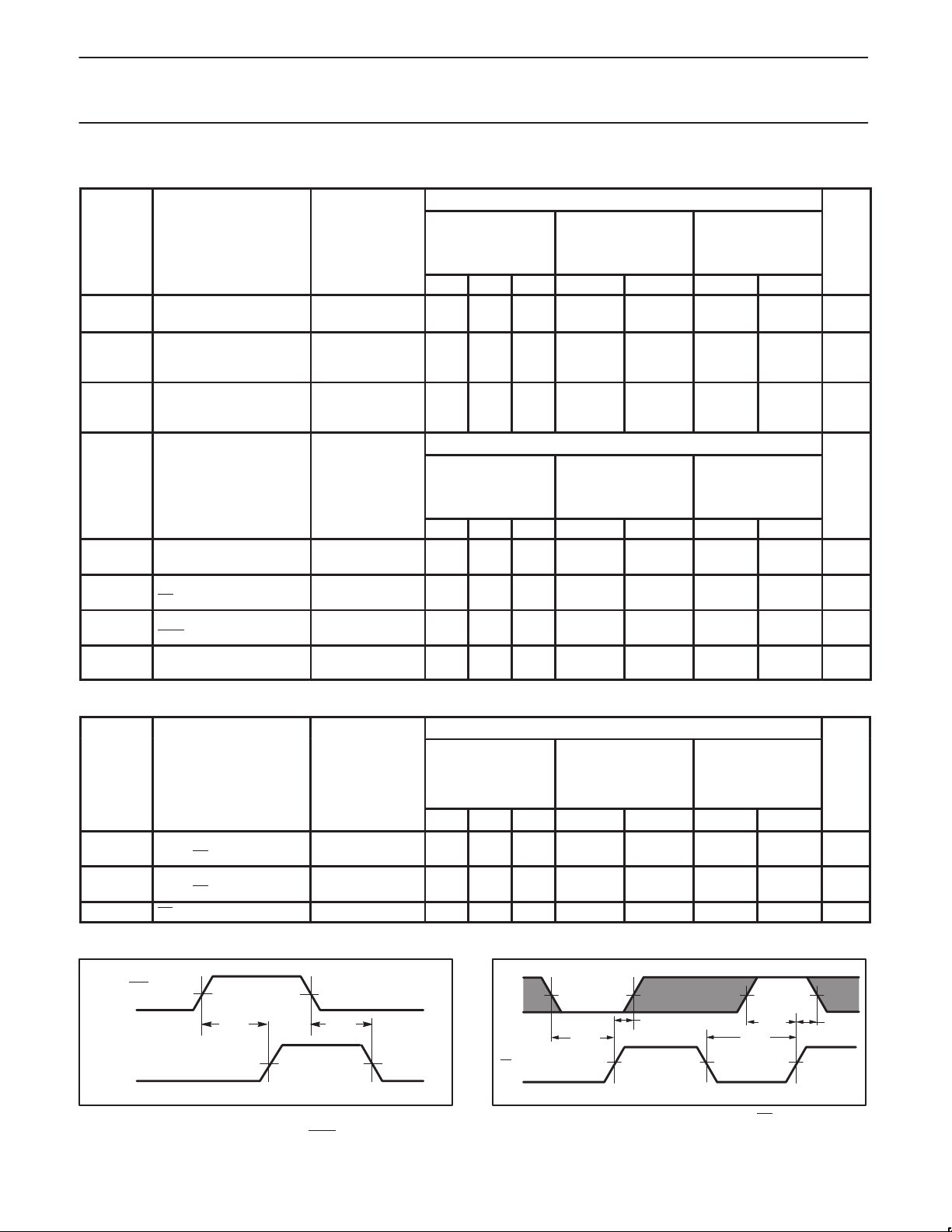
AC ELECTRICAL CHARACTERISTICS
SYMBOL PARAMETER
t
PLH
t
PHL
t
PZH
t
PZL
t
PHZ
t
PLZ
Propagation delay
Bn to An
Output enable time to
High or Low
OEAn
to An
Output Disable time from
High or Low
OEAn to An
SYMBOL PARAMETER
t
PLH
t
PHL
t
PLH
t
PHL
t
PLH
t
PHL
t
TLH
t
THL
Propagation delay
An
to Bn
Propagation delay
LEn to Bn
Enable/disable time
OEBn to An
Transition time, B port
1.3V to 1.7V , 1.7V to 1.3V
TEST
CONDITION
Waveform 1
Waveform 3, 4
Waveform 3, 4
TEST
CONDITION
Waveform 1
Waveform 1
Waveform 1
Test Circuits and
Waveforms
T
= +25°C
amb
VCC = +5.0V
CL = 30pF, RL = 9Ω
MIN TYP MAX MIN MAX MIN MAX
8.5
10.5
7.5
9.5
8.0
10.0
9.0
11.0
1.5
3.0
1.5
3.0
T
= +25°C
amb
VCC = +5.0V
CD= 30pF, RU = 9Ω
MIN TYP MAX MIN MAX MIN MAX
3.0
4.5
5.0
6.5
3.5
5.5
5.5
7.5
3.0
5.0
6.0
8.0
0.5
4.0
0.5
2.0
T
13.0
12.0
13.0
14.0
6.0
6.0
T
7.0
9.0
8.0
10.5
7.5
10.5
4.5
4.5
A PORT LIMITS
= 0°C to +70°C
amb
V
= +5.0V ±10%
CC
= 30pF, RL = 9Ω
C
L
8.0
7.5
7.0
8.0
1.0
1.0
14.5
12.5
14.5
15.5
6.5
6.0
B PORT LIMITS
= 0°C to +70°C
amb
VCC = +5.0V ± 10%
= 30pF, RU = 9Ω
C
D
2.5
4.5
3.0
5.0
3.0
5.5
0.5
0.5
8.0
10.0
9.0
11.5
8.0
12.0
7.0
4.5
T
= –40°C to
amb
+85°C
= +5.0V ±10%
V
CC
= 30pF, RL = 9Ω
C
L
8.0
7.5
7.0
8.0
1.0
1.0
T
= –40°C to
amb
+85°C
= +5.0V ±10%
V
CC
= 30pF, RU = 9Ω
C
D
2.5
4.5
3.0
5.0
3.0
5.5
0.5
0.5
74F777
UNIT
14.5
12.5
14.5
15.5
6.5
6.0
UNIT
8.0
10.0
9.0
11.5
8.0
12.0
7.0
4.5
ns
ns
ns
ns
ns
ns
ns
AC SETUP REQUIREMENTS
LIMITS
T
= –40°C to
amb
+85°C
= +5.0V ±10%
V
CC
= 30pF, RU = 9Ω
C
D
SYMBOL PARAMETER
TEST
CONDITION
T
= +25°C
amb
VCC = +5.0V
CD= 30pF, RU = 9Ω
T
= 0°C to +70°C
amb
V
= +5.0V ± 10%
CC
= 30pF, RU = 9Ω
C
D
MIN TYP MAX MIN MAX MIN MAX
t
(H)
su
t
(L)
su
t
(H)
h
t
(L)
h
t
(L) LEn pulse width, Low Waveform 2 5.5 6.5 6.5 ns
w
Setup time
An to LEn
Hold time
An to LEn
Waveform 2
Waveform 2
4.0
4.5
0.0
0.0
4.5
4.5
0.0
0.0
4.5
4.5
0.0
0.0
AC WAVEFORMS
An, Bn
n
V
M
t
PLH
V
M
t
PHL
V
M
V
M
Waveform 1. Propagation delay, data to output and
enable/disable time OEBn to Bn
SF00437
An
LEn
V
M
tsu(L)
V
M
th(L)
V
M
VMV
M
(H)
t
su
tw(L)
V
M
Waveform 2. Data set-up and hold times and LE pulse width
An, Bn, OEB
V
M
UNIT
ns
ns
th(H)
SF00438
May 19, 1992
7
Page 8
Philips Semiconductors Product specification
Triple bidirectional latched bus transceiver (3–State +
Open Collector)
OEAn
V
M
t
PZH
An
V
V
M
t
PHZ
M
VOH -0.3V
0V
SF00439
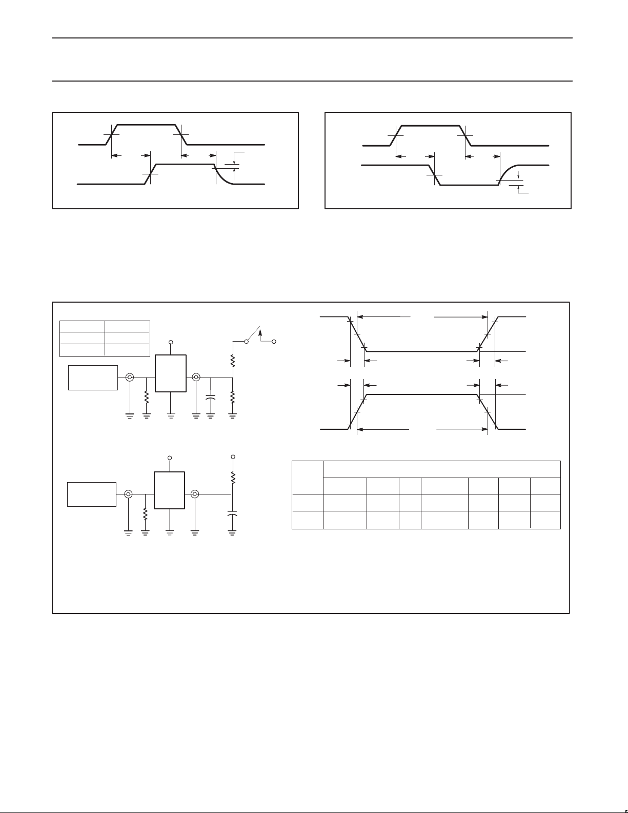
Waveform 3. 3-State output enable time to High level and
output disable time from High level
Notes to AC waveforms
For all waveforms, V
The shaded areas indicate when the input is permitted to change for predictable output performance.
= 1.5V.
M
TEST CIRCUITS AND WAVEFORMS
SWITCH POSITION
TEST SWITCH
, t
t
PLZ
PZL
closed
V
CC
openAll other
PULSE
GENERATOR
V
IN
R
T
D.U.T.
V
OUT
Test circuit for 3–State outputs on A port
V
CC
PULSE
GENERATOR
V
IN
R
T
D.U.T.
V
OUT
R
L
C
R
L
L
7.0V
R
U
C
D
7.0V
NEGATIVE
PULSE
POSITIVE
PULSE
family
A port
OEAn
An
Waveform 4. 3-State output enable time to Low level and output
90%
V
M
10%
t
THL (tf
t
TLH (tr
90%
V
10%
M
Input pulse definition
INPUT PULSE REQUIREMENTS
amplitude
3.0V
Low V
0.0V
1.0V
V
M
t
PZL
V
M
t
PLZ
V
M
disable time from Low level
t
w
V
M
10%
)
)
V
M
1.5V
t
w
rep. rate
)
t
TLH (tr
t
)
THL (tf
90%
V
M
t
w
1MHz 500ns 2.5ns
1MHz 500nsB port 2.0V 1.0V
74F777
AMP (V)
90%
low V
10%
low V
t
TLHtTHL
4.0ns
VOL +0.3V
SF00440
AMP (V)
2.5ns
4.0ns
Test circuit for outputs on B port
DEFINITIONS:
= Load resistor; see AC electrical characteristics for value.
R
L
CL= Load capacitance includes jig and probe capacitance; see AC electrical characteristics for value.
RU= Pull up resistor; see AC electrical characteristics for value.
C
= Load capacitance includes jig and probe capacitance; see AC electrical characteristics for value.
D
RT= Termination resistance should be equal to Z
May 19, 1992
of pulse generators.
OUT
8
SF00431
Page 9
Philips Semiconductors Product specification
Triple bidirectional latched bus transceiver
(3-State + open collector)
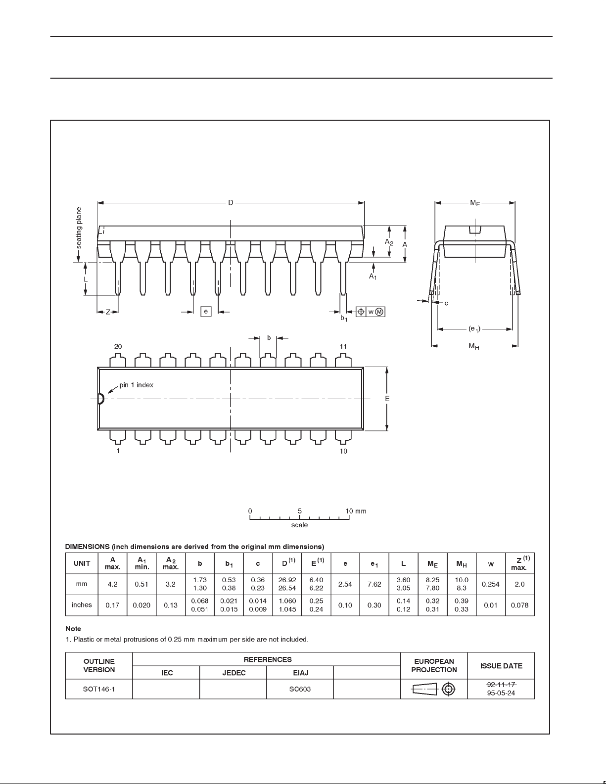
DIP20: plastic dual in-line package; 20 leads (300 mil) SOT146-1
74F777
1992 May 19
9
Page 10
Philips Semiconductors Product specification
Triple bidirectional latched bus transceiver
(3-State + open collector)
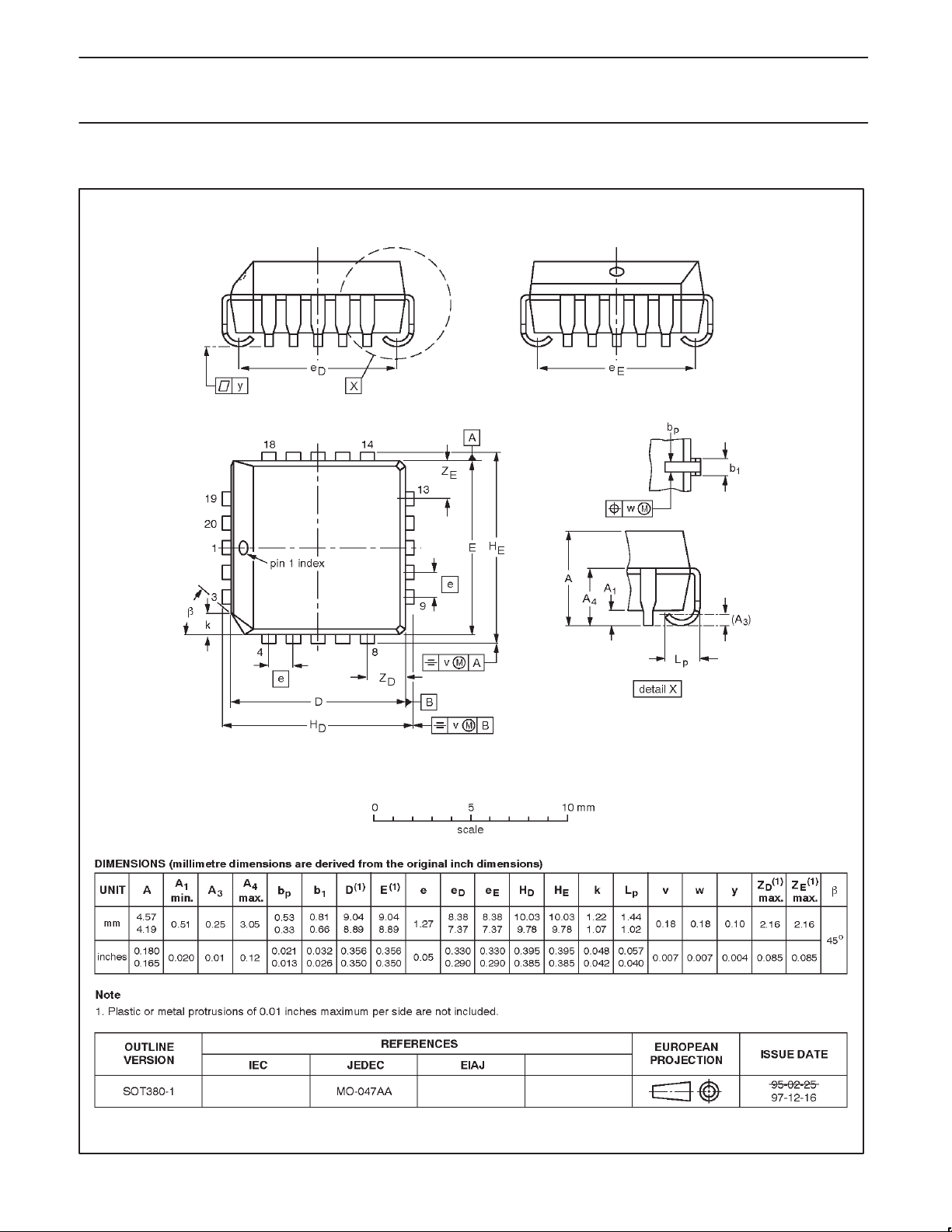
PLCC20: plastic leaded chip carrier; 20 leads SOT380-1
74F777
1992 May 19
10
Page 11

Philips Semiconductors Product specification
Triple bidirectional latched bus transceiver
(3-State + open collector)
NOTES
74F777
1992 May 19
11
Page 12

Philips Semiconductors Product specification
Triple bidirectional latched bus transceiver
(3-State + open collector)
Data sheet status
Data sheet
status
Objective
specification
Preliminary
specification
Product
specification
Product
status
Development
Qualification
Production
Definition
This data sheet contains the design target or goal specifications for product development.
Specification may change in any manner without notice.
This data sheet contains preliminary data, and supplementary data will be published at a later date.
Philips Semiconductors reserves the right to make chages at any time without notice in order to
improve design and supply the best possible product.
This data sheet contains final specifications. Philips Semiconductors reserves the right to make
changes at any time without notice in order to improve design and supply the best possible product.
[1]
74F777
[1] Please consult the most recently issued datasheet before initiating or completing a design.
Definitions
Short-form specification — The data in a short-form specification is extracted from a full data sheet with the same type number and title. For
detailed information see the relevant data sheet or data handbook.
Limiting values definition — Limiting values given are in accordance with the Absolute Maximum Rating System (IEC 134). Stress above one
or more of the limiting values may cause permanent damage to the device. These are stress ratings only and operation of the device at these or
at any other conditions above those given in the Characteristics sections of the specification is not implied. Exposure to limiting values for extended
periods may affect device reliability.
Application information — Applications that are described herein for any of these products are for illustrative purposes only. Philips
Semiconductors make no representation or warranty that such applications will be suitable for the specified use without further testing or
modification.
Disclaimers
Life support — These products are not designed for use in life support appliances, devices or systems where malfunction of these products can
reasonably be expected to result in personal injury . Philips Semiconductors customers using or selling these products for use in such applications
do so at their own risk and agree to fully indemnify Philips Semiconductors for any damages resulting from such application.
Right to make changes — Philips Semiconductors reserves the right to make changes, without notice, in the products, including circuits, standard
cells, and/or software, described or contained herein in order to improve design and/or performance. Philips Semiconductors assumes no
responsibility or liability for the use of any of these products, conveys no license or title under any patent, copyright, or mask work right to these
products, and makes no representations or warranties that these products are free from patent, copyright, or mask work right infringement, unless
otherwise specified.
Philips Semiconductors
811 East Arques Avenue
P.O. Box 3409
Sunnyvale, California 94088–3409
Telephone 800-234-7381
Copyright Philips Electronics North America Corporation 1998
All rights reserved. Printed in U.S.A.
print code Date of release: 10-98
Document order number: 9397-750-05178
yyyy mmm dd
12
 Loading...