

Page 1
查询60CPF10供应商
FAST SOFT RECOVERY
RECTIFIER DIODE
Bulletin I2130 rev. B 01/01
QUIETIR Series
60EPF.. 60CPF.. HV
V
< 1.2V @ 30A
F
Description/Features
The 60EPF.. & 60CPF.. fast soft recovery QUIETIR
rectifier series has been optimized for combined short
reverse recovery time and low forward voltage drop.
The glass passivation ensures stable reliable
operation in the most severe temperature and power
cycling conditions.
Typical applications are both:
output rectification and freewheeling in
inverters, choppers and converters
and input rectifications where severe
restrictions on conducted EMI should be met.
Major Ratings and Characteristics
Characteristics 60EPF.. Units
60CPF..
I
Sinusoidal waveform 60 A
F(AV)
V
range 1000 to 1200 V
RRM
I
FSM
VF@ 30 A, TJ = 25°C 1.2 V
trr@ 1A, - 100A/µs 95 ns
700 A
t
V
Package Outline
60CPF..
= 95 ns
rr
1000 to 1200V
RRM
60EPF..
TJrange - 40 to 15 0 °C
TO-247AC (Modified)
1
Page 2
60EPF.. 60CPF.. HV QUIETIR Series
Bulletin I2130 rev. B 01/01
Voltage Ratings
V
, maximum V
RRM
Part Number
60EPF10, 60CPF10 1000 1100 8
60EPF12, 60CPF12 1200 1300
peak reverse voltage peak reverse voltage 150°C
VVmA
Absolute Maximum Ratings
Parameters 60.PF.. Units Conditions
I
Max. Average Forward Current 60 A @ TC = 103° C, 180° conduction half sine wave
F(AV)
I
Max. Peak One Cycle Non-Repetitive 700 10ms Sine pulse, rated V
FSM
Surge Current 830 10ms Sine pulse, no voltage reapplied
I2t Max. I2t for fusing 2450 10ms Sine pulse, rated V
3460 10ms Sine pulse, no voltage reapplied
2
I
√t Max. I2√t for fusing 34600 A2√s t = 0.1 to 10ms, no voltage reapplied
A
A2s
Electrical Specifications
Parameters 60.PF.. Units Conditions
VFMMax. Forward Voltage Drop 1.4 V @ 60A, TJ = 25°C
r
Forward slope resistance 4.6 mΩ
t
V
Threshold voltage 0.9 V
F(TO)
IRMMax. Reverse Leakage Current 0.1 TJ = 25 °C
8T
mA
TJ = 125°C
= 150 °C
J
, maximum non repetitive I
RSM
RRM
RRM
VR = rated V
applied
applied
RRM
RRM
Recovery Characteristics
Parameters 60.PF.. Units
trrReverse Recovery Time 480 ns IF @ 60Apk
IrrReverse Recovery Current 8 A @ 25A/ µs
QrrReverse Recovery Charge 2.7 µC @ 25°C
S Snap Factor 0.6
Conditions
Thermal-Mechanical Specifications
Parameters 60.PF.. Units Conditions
TJMax. Junction Temperature Range - 40 to 15 0 °C
T
Max. Storage Temperature Range - 40 to 150 °C
stg
R
Max. Thermal Resistance Junction 0.4 °C/W DC operation
thJC
to Case
R
Max. Thermal Resistance Junction 40 °C/W
thJA
to Ambient
R
Typical Thermal Resistance, Case to 0.2 °C/W Mounting surface , smooth and greased
thCS
Heatsink
wt Approximate Weight 6 (0.21) g (oz.)
T Mounting Torque Min. 6 (5)
Max. 12 (10)
Case Style TO-247AC JEDEC (Modified)
2
Kg-cm
(Ibf-in)
www.irf.com
Page 3
150
140
60.PF.. Series
R (D C) = 0.4 C/W
thJC
60EPF.. 60CPF.. HV QUIETIR Series
Bulletin I2130 rev. B 01/01
150
140
60.PF.. Series
R (D C) = 0.4 C/W
thJC
130
120
110
100
90
Maximum Allowable Case Temperature ( C)
0 10203040506070
Average Forward Current (A)
30
Conduction Angle
90
120
60
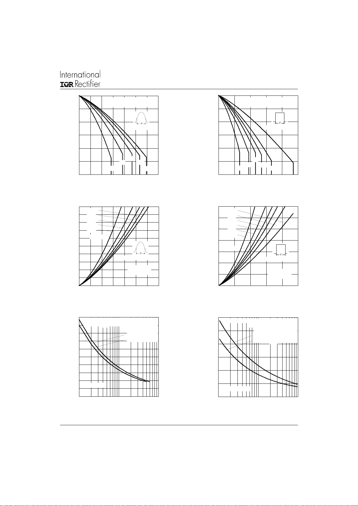
Fig. 1 - Current Rating Characteristics
100
180
90
120
90
80
60
30
70
RMS Limit
60
50
40
30
20
10
0
Ma xim um Average Forward Power Loss (W)
0 10203040506070
Average Forward Current (A)
Conduction Angle
60.PF.. Series
T = 150 C
J
Fig. 3 - Forward Power Loss Characteristics
180
130
120
110
100
30
90
Maximum Allowable Case Temperature ( C)
0 20406080100
Average Forward Current (A)
90
60
Conduction Period
120
180
DC
Fig. 2 - Current Rating Characteristics
140
120
100
DC
180
120
90
60
30
80
RMS Limit
60
40
20
0
Maximum Average Forward Power Loss (W)
020406080100
Conduction Period
60.PF.. Series
T = 150 C
J
Average Forward Current (A)
Fig. 4 - Forward Power Loss Characteristics
800
At Any Rated Load C ondit ion An d W ith
Rate d V A pplie d F ollo win g Surg e.
RRM
700
Initial T = 150 C
J
@ 60 Hz 0.0083 s
@ 50 Hz 0.0100 s
600
500
400
60.P F.. Serie s
Peak Half Sine Wave Forward Current (A)
300
110100
Num ber Of Equal Amplitude Half Cycle Current Pulses (N)
Fig. 5 - Maximum Non-Repetitive Surge Current
www.irf.com
900
800
Maximum Non Repetitive Surge Current
Versus Pulse Train Duration.
Initia l T = 15 0 C
No Voltage Reapplied
Rated V Reapplied
700
RRM
600
500
400
60.PF.. Series
Peak Half Sine Wave Forward Current (A)
300
0.01 0.1 1
Pulse Train Duration (s)
Fig. 6 - Maximum Non-Repetitive Surge Current
J
3
Page 4

60EPF.. 60CPF.. HV QUIETIR Series
Bulletin I2130 rev. B 01/01
1000
60.PF.. Series
100
10
Instantaneous Forward Current (A)
1
00.511.522.53
Instantan eous Forward Voltage (V)
Fig. 7 - Forward Voltage Drop Characteristics
T = 25 C
J
T = 150 C
J
600
n
500
400
300
200
100
Maximum Reverse Recovery Tim e - Trr ( s)
0
04080120160200
60.PF.. Series
T = 25 C
J
I = 60 A
FM
30 A
10 A
5 A
1 A
Rate Of Fall Of Forward Current - di/dt (A/ s)
Fig. 8 - Recovery Time Characteristics, TJ = 25°C
12000
10000
60.PF.. Series
T = 25 C
J
I = 60 A
FM
8000
6000
4000
2000
0
0 40 80 120 160 200
Maximum Reverse Recovery Charge - Qrr ( C)
Rate Of Fall Of Forward Current - di/dt (A/ s)
30 A
10 A
5 A
1 A
Fig. 10 - Recovery Charge Characteristics, TJ = 25°C
1200
n
1000
60.PF.. Series
T = 150 C
J
800
I = 60 A
600
400
200
Ma ximum Reverse Rec overy Time - Trr ( s)
0
0 40 80 120 160 200
FM
30 A
10 A
5 A
1 A
Rate Of Fall Of Forward Current - di/dt (A/ s)
Fig. 9 - Recovery Time Characteristics, TJ = 150°C
25000
60.PF.. Series
20000
T = 150 C
J
I = 60 A
FM
15000
30 A
10000
10 A
5000
0
0 40 80 120 160 200
M aximum Reverse Re covery Charge - Qrr ( C)
Rate Of Fall Of Forward Current - di/dt (A/ s)
5 A
1 A
Fig. 11 - Recovery Charge Characteristics, TJ = 150°C
4
www.irf.com
Page 5

45
60.PF.. Series
40
T = 25 C
J
I = 60 A
FM
35
30
30 A
25
20
15
10
10 A
5 A
1 A
5
0
Maximum Reverse Recovery Current - Irr (A)
0 40 80 120 160 200
Rate Of Fall Of Forward Current - di/dt (A/ s)
Fig. 12 - Recovery Current Characteristics, TJ = 25°C
1
60EPF.. 60CPF.. HV QUIETIR Series
Bulletin I2130 rev. B 01/01
60
60.PF.. Series
T = 150 C
J
50
40
30
20
10
0
Maxim um Reverse Recovery Current - Irr (A)
04080120160200
Rate Of Fall Of Forward Current - di/dt (A/ s)
Fig. 13 - Recovery Current Characteristics, TJ = 150°C
I = 60 A
FM
30 A
10 A
5 A
1 A
thJC
Transient Thermal Impedance Z ( C/W )
0.001
D = 0.50
D = 0.33
0.1
D = 0.25
D = 0.17
D = 0.08
0.01
Single Pulse
0.0001 0.001 0.01 0.1 1 10
Square Wave Pulse Duration (s)
Fig. 14 - Thermal Impedance Z
thJC
Steady State Value
(DC Opera tion )
60.PF.. Se ries
Characteristics
www.irf.com
5
Page 6

60EPF.. 60CPF.. HV QUIETIR Series
Bulletin I2130 rev. B 01/01
Outline Table
15.90 (0 .626)
15.30 (0 .602)
20.30 (0.800)
19.70 (0.775)
1 3
14. 80 (0.583)
14.20 (0. 559)
1.40 (0.05 6)
1.00 (0.03 9)
10.94 ( 0.430)
10.86 (0.427)
Ordering Information Table
Device Code
3.65 ( 0.144)
3.55 ( 0.139)
5. 70 (0.225)
5.30 ( 0.208)
4.30 (0.170)
3.70 (0.145)
2. 20 (0 .087)
MAX.
DIA.
5.50 ( 0.217)
4.50 (0.177)
(2 PLCS.)
Dimensions in millimeters and inches
5. 30 (0.209)
4.70 ( 0.185)
0.80 ( 0.032)
0. 40 (0.213)
2.5 ( 0.098)
1.5 ( 0.059)
2.40 ( 0.095)
MAX.
60 E P F 12
24
1
1 - Current Rating
2 - Circuit Configuration:
3
5
CATHODE
1
CATHODE
BASE
2
3
ANODE
E = Single Diode
3 - Package:
P = TO-247AC (Modified)
4 - Type of Silicon:
F = Fast Recovery
5 - Voltage code: Code x 100 = V
RRM
6
6
10 = 1000V
12 = 1200V
www.irf.com
Page 7

Outline Table
60EPF.. 60CPF.. HV QUIETIR Series
Bulletin I2130 rev. B 01/01
20.30 (0 .800)
19.70 (0 .775)
14.80 ( 0.583)
14.20 (0 .559)
1.40 ( 0.056)
1.00 (0 .039)
10. 94 (0.430)
10.86 (0.427)
15.90 (0 .626)
15.30 (0 .602)
12 3
4.30 (0 .170)
3.70 (0 .145)
Dimensions in millimeters and inches
3. 65 (0.144)
3. 55 (0.139)
5.70 (0.225)
5.30 (0.208)
2. 20 (0.087)
MAX.
DIA.
5.50 ( 0.217)
4. 50 (0.177)
(2 PLCS.)
5. 30 (0.209)
4.70 ( 0.185)
0.80 ( 0.032)
0. 40 (0.213)
2.5 ( 0.098)
1.5 ( 0.059)
2. 40 (0.095)
MAX.
Ordering Information Table
Device Code
60 C P F 12
24
1
1 - Current Rating
2 - Circuit Configuration:
C = Single Diode, 3 pins
3 - Package:
P = TO-247AC (Modified)
4 - Type of Silicon:
F = Fast Recovery
5 - Voltage code: Code x 100 = V
6
www.irf.com
Base Cathode
BASE
2
CATHODE
3
5
CATHODE
Anode
ANODE
1
3
Anode
10 = 1000V
RRM
12 = 1200V
7
Page 8

60EPF.. 60CPF.. HV QUIETIR Series
Bulletin I2130 rev. B 01/01
IR WORLD HEADQUARTERS: 233 Kansas St., El Segundo, California 90245, USA Tel: (310) 252-7105
TAC Fax: (310) 252-7309
Visit us at www.irf.com for sales contact information. 01/01
8
www.irf.com
 Loading...