

Page 1
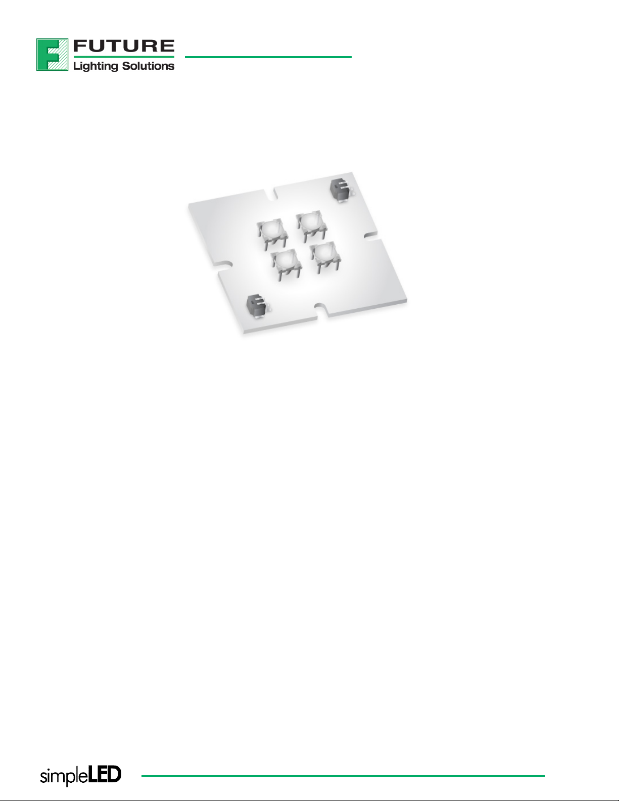
SQUARE LIGHT ENGINE
DATA SHEET
05707 Series
Part of the simpleLED® program
®
2010v1
Page 2
SQUARE LIGHT ENGINE
simpleLED 05707 SERIES
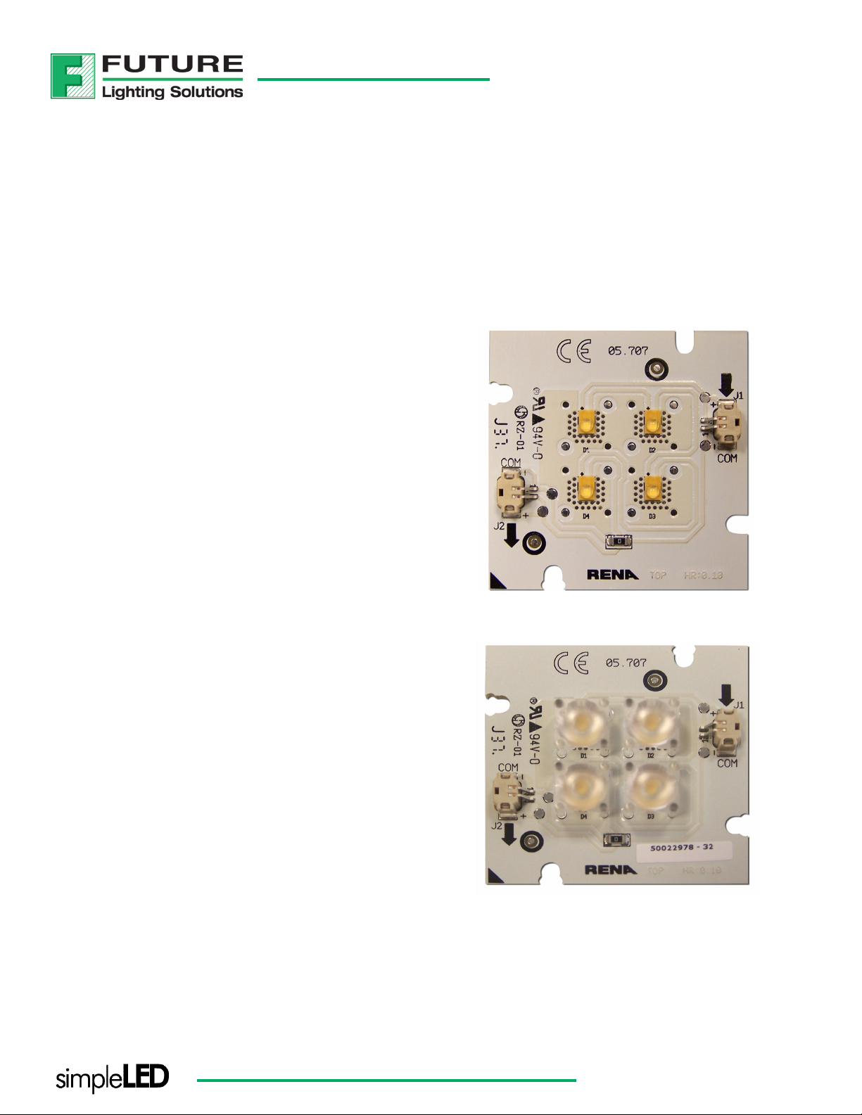
The light engine series consist of 4 high power LUXEON Rebel LEDs. It is engineered to provide customers with the exibility to select the
optimal light source for the applications. Customers can modify the simpleLED light source by selecting the LUXEON Rebel LED, optic and
connector to best suit their needs.
FEATURES & BENEFITS
3 Year Manufacturer (Rena) Warranty
High-Reliability LED Sources
Rugged Construction
Wide Operational Temperature Range
Multiple Congurable Options
Flexible Optic Options
Wide Range Drive Current
Multiple White CCT’s Available
Short Lead Time
CE certied, UL recognized
TYPICAL APPLICATIONS
Under Cabinet Lighting
Cove Lighting
Accent Lighting
Display Case Lighting
Display Lighting
Note: All specications are subject to change without notice.
®
www.FutureLightingSolutions.com
2
Page 3
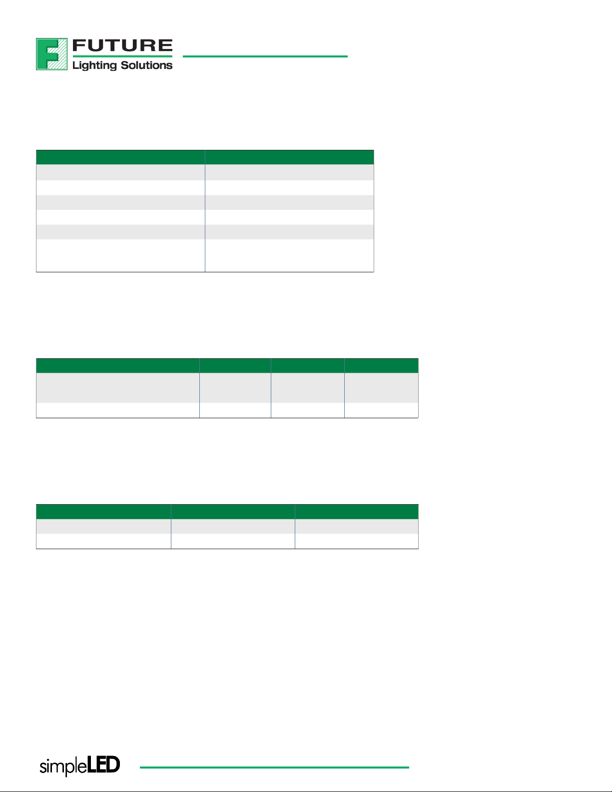
MECHANICAL CHARACTERISTICS
PARAMETER CONDITIONS
PCB FR-4
Finish White
Size 50 x 50 mm
Source Type LUXEON Rebel
Connector Tyco Mini-CT (2106091-1)
Thermal Resistance
(p-n junction to bottom of PCB)
Rth= 21 K/W
ELECTRICAL CHARACTERISTICS
SQUARE LIGHT ENGINE
PARAMETER MIN NOM MAX
Forward Voltage (V)
@350mA & Tj=25 °C
Power Consumption @350mA (W) 3.6 4.2 5.6
10.2 12.0 16.0
ENVIRONMENTAL CHARACTERISTICS
PARAMETER MIN MAX
Storage Temperature (°C) -40 +70
PCB temperature (°C) -20 +80
Note: All specications are subject to change without notice.
®
www.FutureLightingSolutions.com
3
Page 4

SQUARE LIGHT ENGINE
THERMAL STATEMENT & ASSEMBLY INSTRUCTIONS
The light engines must operate under proper environmental conditions and the operating ambient air temperature must not exceed a
certain maximum which cause the LEDs to exceed the maximum junction temperature as stated in Philips Lumileds datasheet. A heat sink
must always be used when operating the light engines. The size of the heat sink depends on the amount of power consumed by the LEDs.
The objective is to maintain the junction temperature below the maximum rating in Philips Lumileds datasheet while also not exceeding
the maximum PCB temperature.
The light engine must be mounted on a at heat sink using M3 screws. All screw holes must be used to attach the light engine to the heat
sink in order to provide proper heat transfer. Also a thermal conductive interface must be used between the heat sink and light engine.
This thermal conductive interface could be a thermal conductive paste such as AmasanT12 from Armack Lottechnik or a thermal interface
material such as T-PCM 585 from Laird.
Note that the bottom of the PCB is not at, since the PCB contains 2 thru board connectors. In order to have a proper heat transfer to the
heat sink, 2 holes at the position of the connector have to be made in the heat sink. A smaller heat sink may be used and therefore may not
require any drilling.
The light engine must not be bent to avoid damaging the LED and/or dislodging the optics. All above specications must be met in order
to qualify for the 3 year warranty.
THERMAL MANAGEMENT
The graphs below show the required thermal resistance of the heat sink based on the maximum operating ambient temperature, the drive
current and the maximum allowable PCB temperature. The maximum allowable Tj is a function of the target lifetime of the light engine
and the LED current. This information can be found in the Philips Lumileds reliability datasheet RD07.
For example, if the maximum ambient temperature is 35°C and the drive current is 500 mA, the heat sink should have a Rth of 5.3 K/W to
meet the max PCB temperature requirement. This is shown in gure 1. With the known Rth of the heat sink, the delta T from junction to
ambient can be determined in gure 2. A Rth of 5.3 K/W has a delta T of 68 °C, which means that the LED has a Tj of 103 °C.
With the same graphs the max operating ambient temperature and the junction temperature can also be determined if the thermal
resistance of the chosen heat sink is known.
Note; the graphs show that not all combinations of Tj and max ambient are possible.
Figure 1 Figure 2
Note: All specications are subject to change without notice.
®
www.FutureLightingSolutions.com
4
Page 5
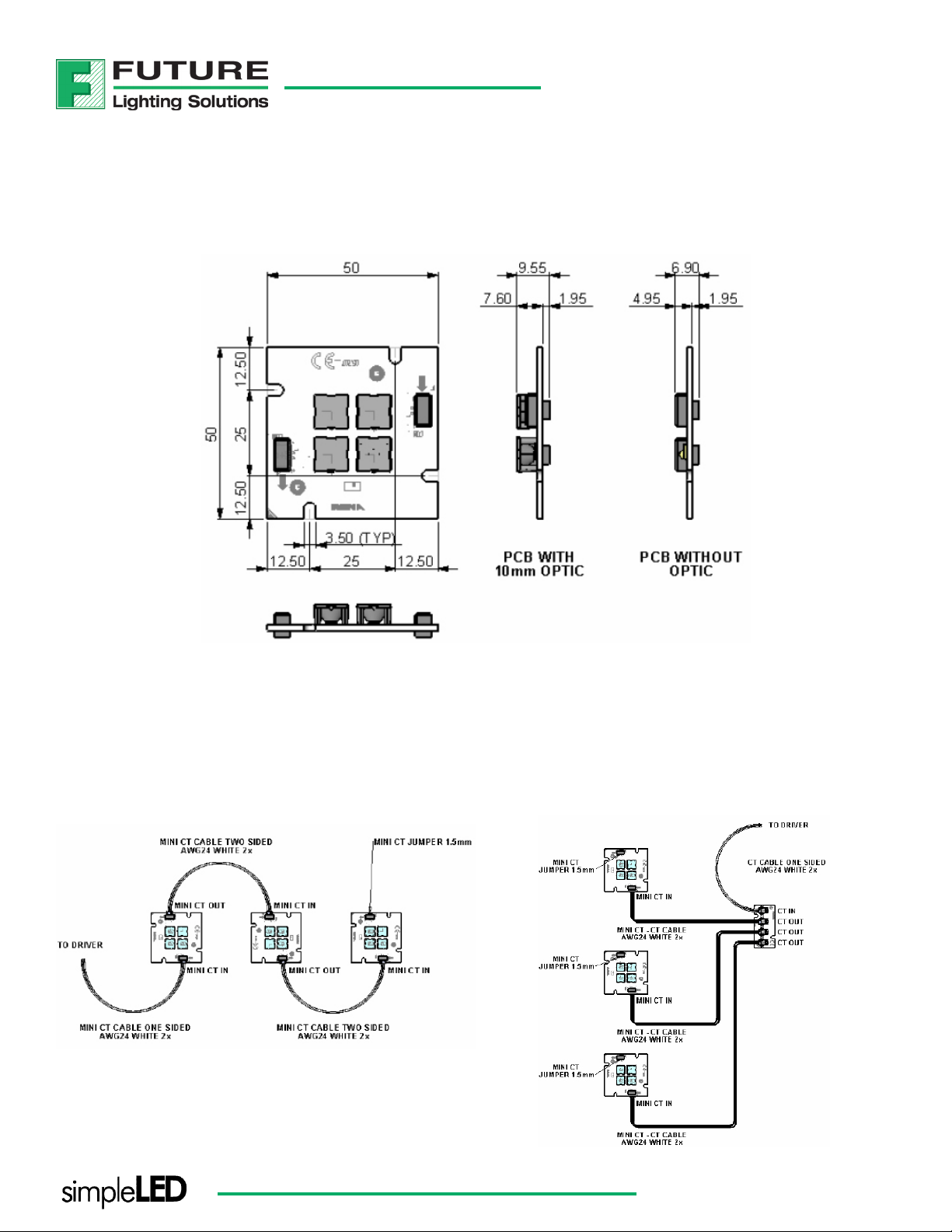
MECHANICAL DRAWINGS
2D drawings with dimensions in mm
SQUARE LIGHT ENGINE
INTERCONNECTIVITY OPTIONS
Board-to-board wiring options and drawings
Boards connected in series:
Note: All specications are subject to change without notice.
®
Boards connected in parallel:
www.FutureLightingSolutions.com
5
Page 6

ACCESSORIES FOR INTERCONNECTIONS
Cable options for board to board connection and for driver connection
(depending on selected driver)
SQUARE LIGHT ENGINE
Part number
Mini CT-Mini CT cable
1969342-6 300 white
1969342-5 150 white
1969342-4 50 white
1969342-3 300 red & black
1969342-2 150 red & black
1969342-1 50 red & black
Part number
CT-Mini CT cable
1969328-6 300 white
1969328-5 150 white
1969328-4 50 white
1969328-3 300 red & black
1969328-2 150 red & black
1969328-1 50 red & black
Cable length (mm)
Cable length (mm)
Wire
colors
Wire
colors
Part number
single Mini CT cable
1969341-6 300 white
1969341-5 150 white
1969341-4 50 white
1969341-3 300 red & black
1969341-2 150 red & black
1969341-1 50 red & black
* Please refer to www.FutureLightingSolutions.com for a detailed explanation on choosing the correct cable assembly.
Note: All specications are subject to change without notice.
Cable length (mm)
®
Wire
colors
www.FutureLightingSolutions.com
6
Page 7

ACCESSORIES FOR INTERCONNECTIONS
Interconnection board for parallel assembly
Part number 57011121
2D drawings with dimensions in mm
SQUARE LIGHT ENGINE
Note: All specications are subject to change without notice.
®
www.FutureLightingSolutions.com
7
Page 8

SQUARE LIGHT ENGINE
PART NUMBERING & ORDERING INFORMATION
1. PRODUCT SERIES
05707
square board with 4 LEDs in series
1. LED TYPE
R = LUXEON Rebel
Part Number:
2. COLOR TEMP
AAAA
7777 = Neutral White
8888 = Warm White
9999 = Cool White
3. MINIMUM CRI*
BB
XX = No Min CRI
55 = Min 55
60 = Min 60
65 = Min 65
70 = Min 70
75 = Min 75
80 = Min 80
85 = Min 85
90 = Min 90
05707RAAAABBCCCDEFG
4. MINIMUM FLUX*
LM CCC
065 = Min 65
066 = Min 66
067 = Min 67
075 = Min 75
080 = Min 80
100 = Min 100
5. CONNECTOR D
C = Connector
N = No Connector
1 2 3 4 5 6 7 8
6. SUPPLIER COLLIMATOR E
X = No Optics
A = Carclo 10mm
* According to Lumileds datasheet
Special congurations available upon request
Contact your local sales representative
Note: All specications are subject to change without notice.
7. OPTIC HOLDER F
X = No Holder
®
8. COLLIMATOR G
X = No Lens
E = Medium Beam
F = Medium Beam Frosted
H = Wide Beam Frosted
K = Elliptical Beam
www.FutureLightingSolutions.com
8
Page 9

SQUARE LIGHT ENGINE
COMPANY INFORMATION
About Future Lighting Solutions
Future Lighting Solutions (www.futurelightingsolutions.com) is a leading provider of LED lighting components and support
services for solid-state lighting products and installations, including engineering expertise, concept development, full
system solutions and online tools that accelerate quality application development. The company is a division of Future
Electronics.
About simpleLED®
Future Lighting Solutions simpleLED program has over 500 combinations of LUXEON® LED & Optic congurations, enabling
you to select the right Light Engine for your application, eliminate prototyping delays and accelerating time to market.
Additional benets include UL recognized quality and a 3 year warranty. Visit our website and start innovating.
CONTACT DETAILS
In North America:
1-888-LUXEON2
Americas@futurelightingsolutions.com
In Europe:
00-800-44FUTURE
Europe@futurelightingsolutions.com
In Asia:
+800-LUMILEDS
Asia@futurelightingsolutions.com
In Japan:
+81-0120-667-013
Japan@futurelightingsolutions.com
Note: All specications are subject to change without notice.
®
Warranty provided by the manufacturer, Rena Electronica BV.
www.FutureLightingSolutions.com
9
 Loading...