

SAFETY PRECAUTIONS
SERVICE WARNING
Only qualified service technicians who are familiar with safety checks
and guidelines should perform service work. Before replacing parts,
disconnect power source to protect electrostatically sensitive parts. Do
not attempt to modify any circuit unless so recommended by the
manufacturer. When servicing the receiver, use an isolation transformer
between the line cord and power receptacle.
SERVICING THE HIGH VOLTAGE AND CRT
Use EXTREME CAUTION when servicing the high voltage circuits. To
discharge static high voltage, connect a 10K ohms resistor in series with a
test lead between the receiver ground and CRT anode lead. DO NOT lift
the CRT by the neck. Always wear shatterproof goggles when handling
the CRT to protect eyes in case of implosion.
X-RAY RADIATION AND HIGH VOLTAGE LIMITS
Be aware of the instructions and procedures covering X-ray radiation. In
solid-state receivers and monitors, the CRT is the only potential source of
X-rays. Keep an accurate high voltage meter available at all times. Check
meter calibration periodically. Whenever servicing a receiver, check the
high voltage at various brightness levels to be sure it is regulating
properly. Keep high voltage at rated value, NO HIGHER. Excessive high
voltage may cause X-ray radiation or failure of associated components.
DO NOT depend on protection circuits to keep voltage at rated value.
When troubleshooting a receiver with excessive high voltage, avoid close
contact with the CRT. DO NOT operate the receiver longer than
necessary. To locate the cause of excessive high voltage, use a variable
AC transformer to regulate voltage. In present receivers, many electrical
and mechanical components have safety related characteristics which are
not detectable by visual inspection. Such components are identified by a
# on both the schematic and the parts list. For SAFETY, use only
equivalent replacement parts when replacing these components.
GENERAL GUIDELINES
Perform a final SAFETY CHECK before returning receiver to customer.
Check repaired area for poorly soldered connections, and check entire
circuit board for solder splashes. Check board wiring for pinched wires or
wires contacting any high wattage resistors. Check that all control knobs,
shields, covers, grounds, and mounting hardware have been replaced. Be
sure to replace all insulators and restore proper lead dress.
SAFETY CHECKS FIRE AND SHOCK HAZARD
Cold Leakage Checks for Receivers with Isolated Ground
Unplug the AC cord, connect a jumper across the plug prongs, and turn
the power switch on (if applicable). Use an ohmmeter to measure the
resistance between the jumped AC plug and any exposed metal cabinet
parts such as antenna screw heads, control shafts, or handle brackets.
Exposed metal parts with a return path should measure between 1M
ohms and 5.2M ohms. Parts without a return path must measure infinity.
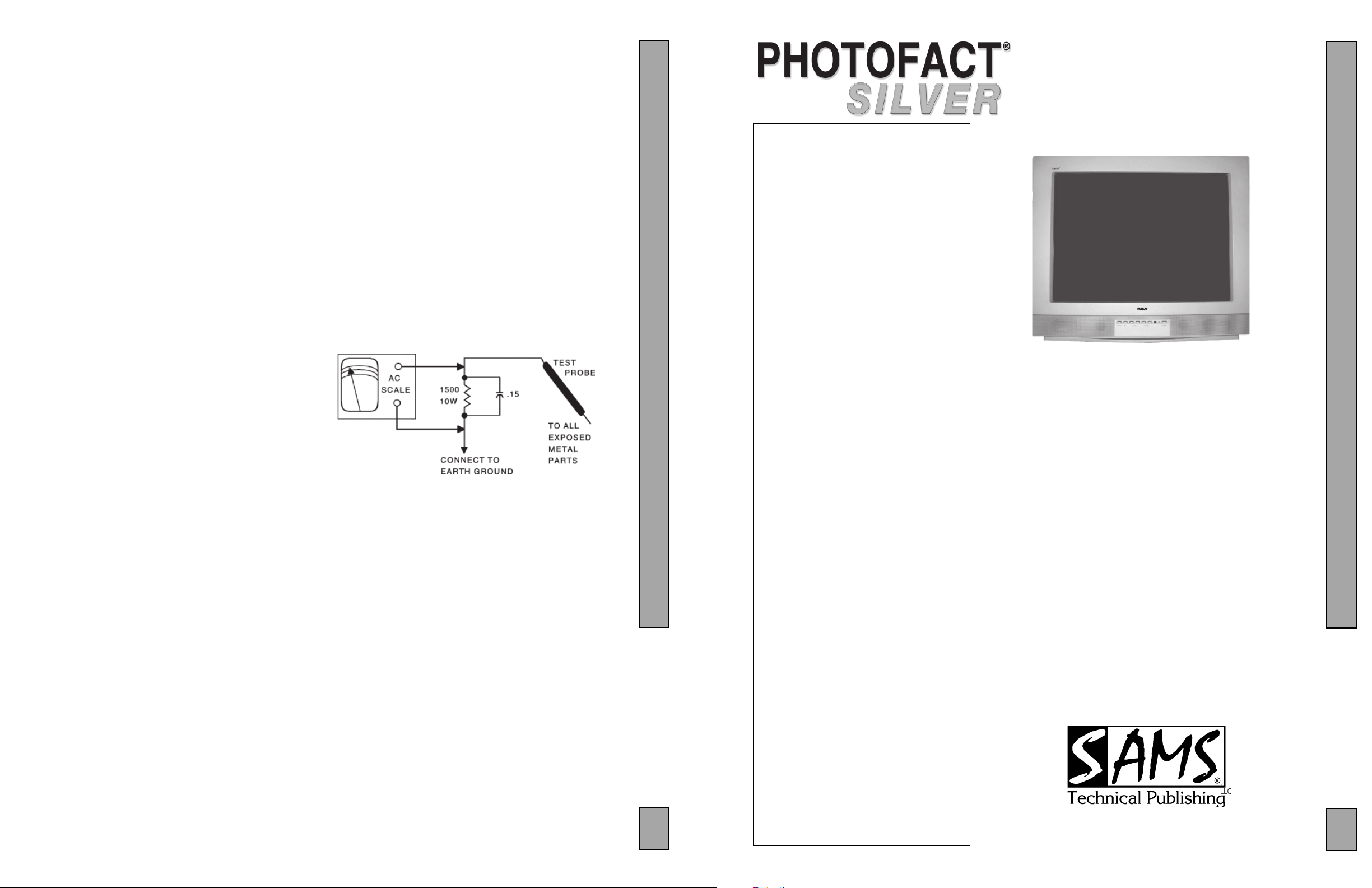
Hot Leakage Current Check
Plug the AC cord directly into an AC outlet. DO NOT use an isolation
transformer. Use a 1500 ohms, 10W resistor in parallel with a .15µF
capacitor to connect between any exposed metal parts on the receiver and
a good earth ground. (See figure below.) Use an AC voltmeter with at
least 5000 ohms per volt sensitivity to measure the voltage across the
resistor. Check all exposed metal parts and measure voltage at each point.
Voltage measurements should not exceed .75VAC, 500µA. Any value
exceeding this limit constitutes a potential shock hazard and must be
corrected. If the AC plug is not polarized, reverse the AC plug and repeat
exposed metal part voltage measurement at each point.
INDEXINDEX
INDEX
INDEXINDEX
SET 5335
GridTrace Location
Main Board ....................................... 3
CRT Board ........................................ 3
Important Parts Information ..................... 3
Miscellaneous Adjustments ..................... 1
Parts List ...................................................4
Placement Chart ....................................... 3
Safety Precautions .................................... 1
Schematic Component Location ..............1
Schematic Notes ....................................... 3
Schematics
Audio/Video Selector........................ 3
Power Supply .................................... 2
Rotation .............................................3
System Control .................................. 2
Television .......................................... 2
Test Equipment ......................................... 3
Tuner Information ....................................1
5335
Technical Service Data
RCA
Model 32V434TYX1 (Chassis ATC010A)
Essential coverage
for servicing a television receiver...
Schematics
The listing of any available replacement part herein in no case constitutes a recommendation, warranty, or guarantee by
SAMS Technical Publishing, LLC as to the quality and suitability of such replacement part. The numbers of the listed parts
have been compiled from information furnished to SAMS Technical Publishing, LLC by the manufacturers of the specific
type of replacement part listed.
Reproduction or use, without express permission, of editorial or pictorial content, in any manner, is prohibited. No patent
liability is assumed with respect to the use of the information contained herein.
© 2008 SAMS Technical Publishing, LLC
9850 E. 30th St.
Indianapolis IN 46229
www.samswebsite.com
Printed in the United States of America 5 4 3 2 1 08PF03438
Page 1 SET 5335
!IBCGC|05335R
5335
MODEL 32V434TYX1 (CHASSIS ATC010A)
RCA
Component locations
Parts list
Coverage includes these additional models and chassis:
Models Chassis
32V434TYX5 ATC010A
32V434TYX6 ATC010A
5335
4
For a Complete List of Manuals,
Visit www.samswebsite.com
JANUARY 2008 SET 5335

Page 1 SET 5335
MISCELLANEOUS ADJUSTMENTS
B+ ADJUSTMENT
1. Tune the set to receive a crosshatch signal.
2. Set the preset picture in the normal mode.
3. Check for 130VDC +/- 1.0V at C828.
RF AGC ADJUSTMENT
The RF AGC is preset at the factory for optimum operation over a wide
range of RF signal input conditions. Readjustment should not be required,
unless the tuner has been repaired or replaced.
Adjustment of the RF AGC parameters may not be apparent, adjusting the
RF AGC from one extreme of its limits to another will render a poor signal
to noise ratio on one end, while adjustments to the other end of its limits
may cause degradation or overload conditions, adjacent channel interference. Use the weakest local signal when adjusting the RF AGC if adjustments are made check all local channels for proper operation.
Input 60db gray scale signal at 100% modulation through the tuner from
the RF-IF output of a video generator, enter the service mode and press 4
on the remote control to select the RF AGC adjustment. Press the INFO
key on the remote control to auto adjust the RF AGC. The status will
change to ‘active’ when the adjustment is complete. The value can be
changed by using the left and right navigation arrows on the remote
control.
SCREEN ADJUSTMENT
Tune the set to receive a crosshatch signal, set the picture color temperature
to normal, set picture brightness and contrast controls to midrange. Enter
the service mode and press the go back button on the remote control, this
will collapse the vertical to a horizontal line. Adjust the screen control to
produce a dim horizontal line, then press the GO Back button on the
remote control to restore the picture.
FOCUS ADJUSTMENT
Tune the set to receive a crosshatch signal adjust the focus control for the
best overall focus.
COLOR TEMPERATURE ADJUSTMENT
Perform the screen adjustment, set the picture color temperature to normal
set picture brightness and contrast controls to midrange. Tune the set to
receive a gray scale stair-step test pattern. Enter the service mode to menu
1 and adjust the value of the high and low controls to proper color tracking
no tinting only black and white and shades of gray the correct color
temperature is 9300 degrees, check the low light to hi light for gray scale
tracking.
SUB BRIGHTNESS ADJUSTMENT
Tune the set to receive a gray scale stair-step test pattern using the A/V
inputs set the picture temperature to ‘normal’ using the customer menu, set
picture brightness and contrast controls to midrange. Enter the service
mode to select Menu 6 with the remote control. Adjust the value of BRTC
Sub-brightness to just lighten the second bar making sure the first bar
remains black.
X-RAY PROTECTION TEST
Tune the set to receive a crosshatch signal. Apply an external power supply
voltage to C417 observe polarity slowly increase the voltage from the
power supply. The set must shut down and remain off when the voltage
reaches 30 volts DC.
ENTERING THE INITIAL SCREEN
To view the initial screen, press the volume down button on the set to
decrease the volume.
to a minimum and while holding the volume down on the set, press the 0
key on the remote two times. Press 0 once again to enter the service mode.
The (example) screen below will be displayed.
VOC300C 2.0.3.2.1 06.08.18 VR4.1D
ADRO 01010000
ADR1 0111000
ADR2 11100111
ADR3 0001111
AFC 00000000
RG 01000000
GG 11000000
BG 01000000
DELF 11001111(varying)
DISC 127(varying)
LAST NV: 6607
ERR: 00000000
REV: 402114
ENTERING SERVICE MODE
To enter the service mode from power on, press the volume down button
on the set to decrease the volume to a minimum and while holding the
volume down on the set, press the 0 key on the remote three times to enter
the service mode.
Press 0 key
VOC300C 2.0.3.2.1 06.08.18 VR4.1D
DEC LVL 0
MONO LVL 0
NIC LVL 0
SAP LVL 0
ADC LVL 0
DCXO CAP 57 57
DISC: 91 TO 255 (Varying)
NICLPINV Inverted
PSCALE 0.375
DCXO: 64
PLIM 96
PCENTER 0
LOUDNESS 6
Press #1 key
VOC300C 2.0.3.2.1 06.08.18 VR4.1D
WPR 19
RED 38
WPG 14
GRN 33
WPB 14
Press #2 key
VOC300C 2.0.3.2.1 06.08.18 VR4.1D
VPOS 48
VAM 30
VSL 26
VL 32
VSC 31
SCL 21
WBR 7
WBF 7
BSWBR 6
BSWBF 6
PRESS #3 key
VOC300C 2.0.3.2.1 06.08.18 VR4.1D
HSH 47
PAR 34
BOW 36
EWW 56
EWP 31
VCR 44
LCR 38
EWT 32
PRESS #4 key
VOC300C 2.0.3.2.1 06.08.18 VR4.1D
RF AGC 20 Active
CEPK PAL 32
CFPEKPAL 3.5+143
CFPEKNTS 3.1+160
CFPEKYUV 4.0+125
IFPL 32
BBTC 32
PGR 64
PGG 64
PGB 64
VG2BRI 20
HDOL 3
PRESS #5 key
VOC300C 2.0.3.2.1 06.08.18 VR4.1D
CNTX 50
CNTN 8
BRTX 40
BRTN 10
COLX 13
COLN 2
TNTX 20
TNTN 20
PRESS #6 key
VOC300C 2.0.3.2.1 06.08.18 VR4.1D
CNTC 11
BRTC 20
COLC 23
TNTCT 31
TNTCA 32
COLP 0
COLS 0
BRTS 0
BUSSTAT 2
RECOVER 6
PRESS #7 key
VOC300C 2.0.3.2.1 06.08.18 VR4.1D
SHPAV4 31
SHPX 31
SHPN 31
OSD BRI 9
CC BRI 10
CCDH 10
CCDV 30
OSD H 13
OSD V 30
MENU V 30
MENU H 7
PRESS #8 key
VOC300C 2.0.3.2.1 06.08.18 VR4.1D
00P1 00001010
0P02 10000001
0P03 00010011
0P04 00100000
0P05 00100100
0P06 00001010
0P07 01000000
0P08 00000101
0P09 10000000
PRESS #9 key
VOC300C 2.0.3.2.1 06.08.18 VR4.1D
MODE 1 01110111
MODE 2 00111111
MODE 3 00001000
MODE 4 11010111
MODE 5 00011101
MODE 6 00110010
MODE 7 00100010
MODE 8 11100010
MODE 9 00100000
MISCELLANEOUS ADJUSTMENTS
(11)
(12)
(9)
(10)
(7)
(8)
(5)
(6)
(3)
(4)
(1)
(2)
SET 5335 Page 1
PRESS Preset key 1 time
BASS M 6
TREBLE M 10
100Hz M 7
300Hz M 9
1Khz M 6
3Khz M 8
8Khz M 10
PRESS Preset key 2 times
BASS S 22
TREBLE S 13
100Hz S 6
300Hz S 9
1Khz S 9
3Khz S 9
8Khz S 6
PRESS Preset key 3 times
BASS T 13
TREBLE T 22
100Hz T 7
300Hz T 8
1Khz T 6
3Khz T 6
8Khz T 9
PRESS Preset key 4 times
BASS STD 28
TREBLE STD 26
100Hz STD 6
300Hz STD 9
1Khz STD 8
3Khz STD 6
8Khz STD 7
PRESS Sleep key
VOC300C 2.0.3.2.1 06.08.18 VR4.1D
Warm R 18
Warm G 11
Warm B 4
Cool R 8
Cool G 10
Cool B 4
exc R 32
exc G 38
exc WR 32
exc WG 32
exc WB 32
PRESS CC key
VOC300C 2.0.3.2.1 06.08.18 VR4.1D
Vol 01 60
Vol 10 92
Vol 90 183
Vol 100 190
YD Av 15
Use the up down arrows to navigate up and down and the left right arrows to change the values.
Menus up to 13 can be selected directly using the remote control buttons 0~9 preset button, sleep
button, CC button. Press the antenna button to save the settings and exit the service mode.
Several factor alignments appear in the menus but only the ones listed should be changed in some
cases the value (hex number) can be changed but the actual value the set is using cannot be changed
except at the factory using factory equipment.
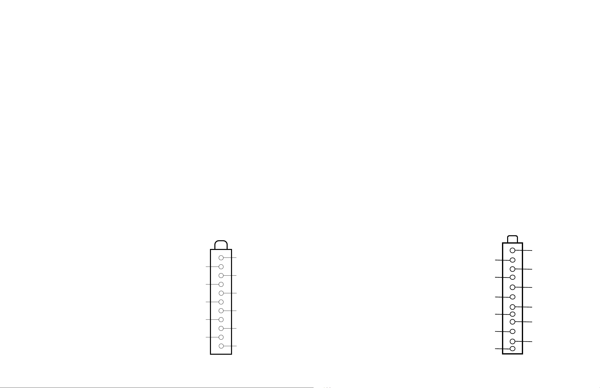
TUNER INFORMATION
ANALOG TUNER VOLTAGE CHART
ANALOG TUNER TERMINAL GUIDE
Pin VHF Low Band VHF High Band UHF Band
(1) AGC 4.3V 4.3V 4.3V
(2) NC - - (3) GND 0V 0V 0V
(4) SCL 2.2V 2.2V 2.2V
(5) SDA 3.6V 3.6V 3.6V
(6) VCC 4.9V 4.9V 4.9V
(7) VCC 4.9V 4.9V 4.9V
(8) NC - - (9) +33V 33.0V 33.0V 33.0V
(10) NC - - (11) IF 0V 0V 0V
NOTE: VHF Low Band voltages taken on channel 2.
VHF High Band voltages taken on channel 7.
UHF Band voltages taken on channel 14.
NO Change between channels.
(2)
(4)
(6)
(8)
(10)
(1)
(3)
(5)
(7)
(9)
(11)
DIGITAL TUNER VOLTAGE CHART
Pin DIGITAL
(1) RF AGC .04V
(2) BC 0V
(3) +5V 5.0V
(4) VT 1.0V
(5) SDA 4.9V
(6) SCL 4.9V
(7) +5V 4.9V
(8) IF OUT 0V
(9) NC
(10) IF AGC .76V
(11) IF1 0V
(12) IF2 0V
NO Change between channels.
DIGITAL TUNER TERMINAL GUIDE

SCHEMATIC COMPONENT LOCATION GUIDE
(P905) D33
C003 C31
C004 D31
C005 C31
C017 E36
C018 B30
C019 E36
C021 C35
C022 A37
C023 A37
C026 B31
C027 A31
C029 C37
C081 D23
C082 D24
C083 D24
C090 C23
C091 C23
C092 C23
C093 C23
C094 C22
C095 C24
C100 C2
C102 B1
C103 B1
C105 A24
C106 A23
C107 B2
C108 C3
C109 B4
C110 C4
C200 D35
C201 D35
C203 D36
C204 D1
C205 C4
C206 B5
C207 D5
C208 D37
C209 D5
C210 D37
C211 B7
C212 C5
C213 E4
C214 C6
C215 C7
C216 C9
C217 C5
C218 E21
C219 E21
C222 D35
C223 D36
C224 D35
C225 D36
C227 E36
C228 B7
C229 C6
C231 D34
C232 D34
C233 A34
C234 B6
C235 C7
C236 E34
C237 E34
C238 D37
C239 D37
C240 E35
C241 C7
C242 C7
C243 B36
C244 A36
C245 A36
C246 D34
C247 B36
C248 C34
C249 C34
C250 C9
C251 C9
C252 C10
C253 C10
C254 A12
C255 C8
C256 C8
C257 E35
C258 E35
C259 B12
C260 C11
C261 C29
C262 C29
C264 C9
C265 B36
C266 B36
C267 B36
C268 C12
C270 C12
C271 E35
C272 C7
C281 B30
C282 D21
C283 E31
C284 A30
C300 E7
C307 E6
C308 C27
C313 D7
C323 D6
C324 D27
C325 D7
C334 D6
C337 C7
C342 D8
C350 D6
C351 D6
C360 C28
C400 A26
C401 B26
C402 E7
C404 E6
C405 E5
C406 E8
C407 E4
C408 E8
C410 E10
C411 E5
C412 E5
C413 E10
C414 D10
C415 C27
C416 D26
C417 E2
C418 C27
C419 D26
C420 E2
C421 E13
C503 A27
C504 A28
C505 D15
C511 B13
C512 A14
C521 C13
C522 C14
C531 C13
C532 B14
C540 C15
C600 D38
C601 D39
C604 D38
C605 D39
C606 E38
C614 E38
C615 E39
C616 E38
C070A A29
C801 A17
C802 A18
C803 A18
C804 A19
C805 A19
C806 A20
C807 A20
C809 C18
C810 C19
C811 C19
C812 C19
C813 C18
C814 C19
C815 C20
C816 C19
C820 B21
C821 B21
C822 B22
C823 A23
C824 B23
C825 D22
C826 A21
C827 A22
C828 A21
C829 B23
C831 B22
C832 B21
C835 C17
C836 C17
C837 D22
C838 B21
C839 D22
C840 B20
C841 B22
C842 B22
C860 D18
C861 D18
C862 E17
C863 E17
C864 E18
C865 D31
C866 D20
C867 D21
C868 D20
C890 E18
C891 D17
C892 D17
C893 E17
C894 D18
C895 E20
C902 B38
C903 B38
C904 B37
C905 B37
C906 B34
C907 B34
C908 B34
C909 B34
C910 A34
C911 A34
C912 B34
C914 C34
C915 B34
C917 C34
C918 B34
C919 B34
C920 A34
C922 D33
C923 C33
C926 C34
C927 C34
C928 D34
C929 D34
C930 D34
C960 E34
C961 E34
C1301 C24
C1302 B43
C1303 C43
C1304 C43
C230A C7
C235A C7
C804A B18
C805A A18
CRT500 C16
D003 C36
D006 B29
D008 C38
D010 E3
D080 E23
D100 C2
D102 A23
D204 C12
D226 E1
D280 D2
D281 E2
D282 E3
D283 E3
D300 E7
D304 E14
D305 E14
D306 D7
D307 D7
D308 D7
D309 D7
D400 A26
D401 E9
D402 E9
D404 C27
D405 D26
D406 E2
D408 E4
D409 E5
D411 E7
D412 E8
D413 E2
D511 B13
D521 C13
D531 C13
D540 C15
D600 E38
D621 E40
D622 E38
D623 D37
D810 C19
D811 C19
D812 C19
D813 C18
D820 B21
D821 D22
D822 A21
D823 B21
D824 C18
D860 D18
D861 D17
D862 D17
D863 D17
D864 D17
D865 E18
D866 E17
D867 D32
D868 D19
D869 E20
D900 A33
D901 B33
D902 A33
D903 C33
D904 D33
D905 C33
D906 D33
D907 D34
D1001A E31
DB801 A19
DEGAUSS B18
F800 A17
IC001 C31
IC090 C23
IC091 C23
IC200 A30
IC200 B5
IC200 B9
IC200 C35
IC200 D3
IC301 D6
IC601 D39
IC801 B19
IC802 B18
IC803 B17
IC804 D19
IC860 D18
IR001 A29
K802 A18
K802 D32
L001 E36
L002 A37
L101 B1
L102 C3
L200 C5
L201 D36
L202 D36
L203 E35
L204 C7
L205 C7
L206 C8
L207 C10
L208 C8
L209 C8
L210 C11
L211 D30
L400 D10
L403 E5
L404 D10
L501 A16
L801 A22
L802 D22
L803 B20
L804 D22
L805 D24
L806 A20
L807 B22
L808 A21
L861 D20
P601 C40
P602 D40
P800 A17
P900 A39
P900 B39
P900 B39
P901 A33
P901 B33
P901 B33
P902 B33
P902 B33
P902 C33
P903 A33
P904 C33
P904 C33
P904 D33
P961 D33
P952L E33
P952R E33
P953V D33
Q001 C35
Q080 D23
Q101 B3
Q200 E23
Q201 E22
Q202 E21
Q203 E21
Q204 C10
Q205 C38
Q206 A12
Q207 C12
Q208 B12
Q211 E35
Q280 E2
Q281 E3
Q402 E6
Q403 E5
Q405 E8
Q407 E4
Q408 E13
Q511 A13
Q512 A14
Q513 B14
Q521 C13
Q522 C14
Q523 C14
Q531 B13
Q532 B14
Q533 C14
Q601 E38
Q602 D38
Q860 E20
Q861 D31
Q900 A38
Q901 A38
Q902 B37
Q903 B37
Q1301 A41
Q1302 A42
Q1303 A43
Q1304 B43
Q1305 C43
Q1306 C43
R009 C31
R010 D31
R011 C31
R014 C35
R015 C35
R016 C35
R017 C35
R018 E31
R022 C37
R023 C37
R024 B30
R025 A30
R026 A30
R027 A31
R028 D35
R029 B31
R030 E3
R031 D3
R033 B29
R034 A30
R035 D35
R036 E30
R039 C30
R042 D34
R045 D35
R047 D31
R048 C30
R049 D31
R050 C37
R051 C37
R052 C38
R081 D23
R090 C22
R100 C3
R101 C3
R103 C2
R104 B1
R109 C1
R111 C3
R114 B2
R115 C3
R116 B3
R117 B2
R118 B3
R130 A31
R131 B31
R200 D1
R201 D1
R202 B37
R203 B37
R204 D1
R205 C5
R206 B5
R207 D5
R208 D5
R209 E4
R210 C7
R211 E22
R212 E22
R213 E22
R214 E21
R215 E21
R216 D21
R217 D4
R218 E35
R219 E35
R220 E34
R221 D2
R222 D4
R223 D4
R225 A37
R226 E1
R227 C9
R228 C10
R229 C11
R230 A12
R231 C11
R232 B12
R234 E1
R235 E1
R236 D1
R237 C8
R238 C8
R023A B29
R240 C10
R241 B6
R244 C9
R245 C9
R024A B29
R250 B36
R251 B36
R252 B36
R253 B36
R255 A12
R256 C12
R257 B12
R025A B29
R260 B36
R261 A36
R262 A36
R026A C29
R270 C11
R271 C11
R027A C29
R282 E3
R283 E3
R284 E2
R285 D2
R300 E7
R313 D7
R314 D5
R315 D7
R316 D6
R321 D8
R324 D8
R0333 C29
R033A E31
R350 D5
R401 D10
R406 E6
R407 E2
R409 E7
R410 E8
R411 E6
R412 E5
R413 E5
R418 E4
R419 D10
R420 E5
R421 A16
R422 A16
R424 E1
R425 E1
R426 C26
R427 D25
R428 E14
R429 E13
R433 E1
R435 A27
R501 D14
R505 A27
R511 A13
R512 A13
R513 A13
R514 A13
R515 B14
R516 A14
R517 A14
R518 B14
R519 A14
R521 C13
R522 C13
R523 C13
R524 C13
R525 C14
R526 C14
R527 C14
R528 C14
R529 C14
R531 B13
R532 B13
R533 B13
R534 B13
R535 B14
R536 B14
R537 B14
R538 C14
R539 B14
R540 C16
R541 C16
R542 C16
R600 D38
R601 D38
R602 D38
R603 D38
R606 D39
R607 D39
R608 D37
R609 E37
R610 E38
R611 E39
R612 D39
R613 E38
R622 D40
R070A A29
R801 A17
R810 B19
R811 B18
R812 C18
R813 C20
R814 C19
R815 C19
R816 C20
R818 C19
R820 B21
R822 B21
R823 D21
R826 A22
R830 C18
R832 C18
R833 C17
R835 C17
R839 C17
R840 B20
R841 C17
R842 B17
R849 E17
R860 D18
R861 E18
R862 E18
R863 E17
R864 E17
R865 E18
R867 E20
R868 E20
R869 E20
R890 D20
R893 D31
R900 B33
R901 B33
R902 B38
R903 B38
R904 B38
R905 B38
R906 A33
R907 B34
R908 A38
R909 B34
R910 A38
R911 A34
R912 A38
R913 C33
R914 B33
R915 C34
R916 B34
R917 B33
R918 A33
R919 B34
R920 A34
R921 C33
R922 D33
R923 C33
R924 D33
R925 D33
R926 C34
R927 C34
R928 D34
R929 D34
R932 D34
R960 E33
R961 E33
R962 E34
R963 E34
R1301 C23
R1302 B43
R1303 A43
R1304 B42
R1305 C43
R1306 A42
R1307 A41
RF IN A1
RT801 A18
RT802 A20
RT860 D17
S008 C29
S001A B29
S002A B29
S003A B29
S004A C29
S005A C29
S006A C29
T401 D7
T402 B26
T402 D12
T801 A17
T802 A18
T803 A20
T860 D19
TU100 B2
Z100 B4
Z101 B4
Z200 C36
RCA MODEL 32V434TYX1 (Chassis ATC010A)
SET 5335 Page 1
Page 2 SET 5335

SET 5335 Page 2

Page 2 SET 5335
PHILIPS MODEL 32PT5441/37 (CHASSIS L04.1UAA)

RCA MODEL 32V434TYX1 (Chassis ATC010A)
PHILIPS MODEL 32PT5441/37 (CHASSIS L04.1UAA)
SET 5335 Page 2

Page 3 SET 5335

CRT BOARD
SET 5335 Page 3
CRT BOARD, GRIDTRACE LOCATION GUIDE
C503 A5
C504 A3
C505 F4
C511* H3
C512* F3
C521* E1
C522* F1
C531* H4
C532* F4
C540 A2
D511* G2
D521* E1
D531* G4
D540 A2
L501 B4
P500 D3
P502 B4
P503 G1
P504 B3
Q511 G3
Q512 G3
Q513 F3
Q521 F1
Q522 E1
Q523 E2
Q531 G5
Q532 G5
Q533 F5
R501 F2
R505 B5
R511* H3
R512* H3
R513* G3
R514* H3
R515 G2
R516 G2
R517* F3
R518 F4
R519 E4
R521* G1
R522* G1
R523* E1
R524* E1
R525 G2
R526 G1
R527* F1
R528 F2
R529 E2
R531* H5
R532* H5
R533* G4
R534* H4
R535 G4
R536 G4
R537* F4
R538 G4
R539 D5
R540 A3
R541 B1
R542 A4
* Located on
other side of
board.

SET 5335 Page 3SET 5335 Page 3

TEST EQUIPMENT
Test equipment listed by participating manufacturer illustrates
typical or equivalent equipment used by Sams engineers to obtain
measurements. This equipment is compatible with most types used
by field service technicians.
Equipment Sencore No.
Oscilloscope SC3100
Generators
RGB CM2125
Multiburst Signal VG91
Color Bar VG91
TV Stereo VG91
Digital VOM SC3100
Frequency Meter SC3100
Hi-Voltage Probe HP200
Accessory Probes TP212
Isolation Transformer PR570
Capacitance Analyzer LC102
CRT Analyzer CR7000
AC Leakage Tester PR570
Inductance Analyzer LC102
Flyback Yoke Tester TVA92
Field Strength Meter SL753
Transistor Tester TF46
Horizontal Analyzer HA-2500
Video Analyzer VG91, TVA92
RCA
MODEL 32V434TYX1 (Chassis ATC010A)
Important Parts Information
n Parts not listed in the parts list are commonly available at your local electronics parts retailer.
n The parts listed here are those not usually available from a well-stocked supply cabinet or bin.
n Where items may be replaced with equivalent parts, several alternates are shown from participating vendors.
n On the parts lists, safety items are marked with a # to remind you that only exact replacements are recommended for
these items.
n When ordering parts, state the model number, part number, and description.
Obtaining Parts
Many of these parts are available from your local Sams authorized distributor or the manufacturer of the equipment. Call
Sams for the name of your nearest distributor:
800-428-7267
Participating Vendors
Information on test equipment and replacement parts is listed in these pages for the following participating vendors.
n NTE Electronics, Inc. (NTE) n Sencore, Inc.
BRAND NAME MODEL XXXX (CHASSIS XXXX)
SET 5335 Page 3

Page 4 SET 5335
MAIN BOARD TOP
MAIN BOARD TOP, GRIDTRACE LOCATION GUIDE
C019 C6
C021 C5
C029 F7
C081 E4
C083 E4
C090 A4
C093 A4
C094 D4
C095 D4
C100 C11
C103 A11
C105 A10
C200 B9
C203 B8
C206 B7
C208 B7
C212 B6
C215 B6
C219 B6
C223 C6
C225 C6
C227 C6
C228 B9
C230A B10
C231 D9
C234 B9
C235A C10
C236 C9
C237 C9
C238 D9
C239 D9
C240 F9
C241 E9
C250 E8
C253 E8
C257 E8
C262 E7
C265 B8
C266 B8
C300 H9
C307 H9
C308 H8
C313 I10
C323 I10
C324 H9
C325 J10
C334 I9
C342 K9
C360 H10
C400 O12
C401 N12
C402 J12
C404 I12
C406 H12
C408 L12
C410 L11
C411 J11
C412 J11
C413 L11
C414 K10
C415 N8
C416 L8
C417 P12
C418 N8
C419 M8
C420 P8
C421 O11
C600 I5
C601 I5
C604 G5
C605 H5
C606 H5
C615 H5
C616 I6
C801 I1
C802 L1
C803 L1
C804 O3
C804A K3
C805 O2
C805A J3
C806 O3
C807 N3
C809 I4
C810 O5
C811 O5
C812 N5
C813 O5
C814 O5
C815 N6
C816 N4
C820 K4
C821 K4
C822 K4
C823 K8
C824 I7
C825 L5
C826 L7
C827 K6
C828 L6
C829 I7
C831 J6
C832 K5
C837 L5
C838 J5
C839 K6
C840 M3
C841 J5
C842 J6
C860 E1
C861 G1
C864 G2
C866 F3
C867 F4
C868 F4
C890 F2
C891 H1
C892 H2
C893 F1
C894 E2
C904 B9
C905 B9
C908 F11
C909 F11
C911 F11
C917 D11
C918 C11
C919 D11
C1301 G4
C1302 H4
C1303 G4
C1304 H3
D003 C6
D006 D4
D008 F7
D010 F6
D080 E4
D100 A12
D102 C10
D204 F9
D226 A8
D280 G12
D281 G12
D282 G12
D283 G10
D300 H10
D304 G9
D305 G9
D306 H10
D307 I10
D308 I10
D309 H10
D400 N12
D401 K10
D402 K11
D404 N8
D405 M8
D406 O11
D408 G10
D409 I12
D411 J11
D412 H12
D413 O7
D600 I6
D621 H7
D622 I6
D623 G6
D810 O4
D811 O5
D812 O5
D813 P4
D820 K4
D821 L5
D822 L7
D823 K5
D824 J4
D860 F2
D861 H1
D862 H2
D863 H2
D864 H1
D865 G2
D866 G2
D867 L3
D868 F3
D869 G3
D900 F12
D901 D11
D902 F12
D903 D11
D904 D11
D905 E11
D906 D10
D907 D10
DB801 O2
F800 I2
IC001 A4
IC090 B4
IC091 C4
IC301 I10
IC601 H5
IC801 O6
IC802 M4
IC803 J3
IC804 G2
IC860 F1
K802 L2
L001 D6
L002 E5
L101 B10
L102 A9
L200 A6
L201 C5
L202 C5
L203 C6
L204 B9
L205 B9
L206 E9
L207 F8
L208 F8
L209 F8
L210 F8
L211 F7
L400 K9
L403 I11
L404 J9
L801 K7
L802 K5
L803 N6
L804 K5
L805 K5
L806 N3
L807 J6
L808 L7
L861 F4
P001 E6
P003 A5
P008 E6
P130 A12
P200 C10
P202 E10
P203 E10
P209 B9
P400 L10
P402 H12
P403 N12
P600 I5
P601 H5
P802 I1
P803 M1
P807 K6
P900 B12
P1301 H3
Q080 E4
Q101 A9
Q201 A5
Q203 B6
Q211 F3
Q402 I12
Q405 L12
Q407 G11
Q861 L3
Q1303 I4
Q1304 H3
Q1305 H3
Q1306 G3
R009 A5
R022 D4
R023 E4
R024 D5
R030 F6
R031 D5
R033 D4
R081 F4
R090 C9
R111 A9
R115 A9
R213 A6
R216 A6
R218 F9
R237 E9
R255 F9
R256 F9
R257 F10
R271 F9
R282 G12
R313 J9
R315 J9
R321 I9
R324 L9
R401 L10
R406 I1
R407 O11
R409 J11
R410 J11
R411 I12
R413 I12
R419 J9
R420 H11
R421 O11
R422 O11
R424 O8
R425 O8
R426 N8
R427 M8
R428 O8
R429 O11
R433 O8
R435 N12
R606 H6
R608 H6
R609 H6
R611 J4
R801 I1
R810 P3
R811 O4
R812 O5
R813 N5
R814 O5
R815 O6
R816 P6
R818 N5
R820 L4
R822 L4
R823 L5
R826 J8
R830 L4
R835 J7
R839 I4
R840 M3
R841 I4
R842 J3
R849 G1
R860 E1
R861 G2
R862 F2
R865 G2
R868 G3
R869 G3
R890 G3
R1301 G5
RT801 N1
RT802 N3
RT860 H1
T401 J12
T402 N11
T801 J2
T802 O1
T803 M5
T860 F2
TU100 A11
Z100 B7
Z101 B8
Z200 C7

MAIN BOARD BOTTOM
MAIN BOARD BOTTOM, GRIDTRACE LOCATION GUIDE
C003 A8
C004 A7
C005 A8
C017 C7
C018 D6
C022 D7
C023 D7
C026 E7
C027 E7
C082 E9
C091 A9
C092 B9
C102 A2
C106 C3
C107 B3
C108 A4
C109 A6
C110 B6
C201 C5
C204 B5
C205 B5
C207 B6
C209 B6
C210 C6
C211 C6
C213 B6
C214 C6
C216 C7
C217 C6
C218 C7
C222 C7
C224 C7
C229 C4
C232 D4
C233 C3
C235 C3
C242 D4
C243 D4
C244 D4
C245 D4
C246 D4
C247 E4
C248 D4
C249 E4
C251 D4
C252 F4
C254 F3
C255 F5
C256 F5
C258 E5
C259 F3
C260 E5
C261 E5
C264 C7
C267 D4
C268 F3
C270 F5
C271 C7
C272 B4
C281 E7
C282 E7
C283 E7
C284 E7
C337 I4
C350 I4
C351 I4
C405 H1
C407 G2
C614 H8
C835 J10
C836 J10
C862 F12
C863 F12
C865 K10
C895 G10
C902 B2
C903 B3
C906 F2
C907 F1
C910 F2
C912 D2
C914 C2
C915 C2
C920 E2
C922 D1
C923 D1
C926 E2
C927 E2
C928 E2
C929 D3
C930 D4
C960 C3
C961 D4
IC200 C6
Q001 D7
Q200 B7
Q202 B7
Q204 E4
Q205 F6
Q206 F4
Q207 F3
Q208 F3
Q280 G1
Q281 G2
Q403 I1
Q408 P2
Q601 I7
Q602 I7
Q860 G10
Q900 C2
Q901 C2
Q902 B2
Q903 B3
Q1301 H9
Q1302 H9
R010 A7
R011 A8
R014 D7
R015 D7
R016 D7
R017 D7
R018 C8
R025 E7
R026 E7
R027 E7
R028 E7
R029 E7
R034 E6
R035 E6
R036 E6
R039 D7
R042 E7
R350 I4
R412 H1
R418 G2
R600 I8
R601 I8
R602 G8
R603 G8
R607 H8
R610 I7
R612 H8
R613 I7
R622 H7
R832 M9
R833 J10
R863 F12
R864 F12
R867 G10
R893 K10
R900 E1
R901 E1
R902 B2
R903 B3
R904 B2
R905 B2
SET 5335 Page 4
R906 E1
R907 F2
R908 B2
R909 F1
R910 B2
R911 F2
R912 C2
R913 C1
R914 C1
R915 C2
R916 C2
R917 C1
R918 F1
R919 C2
R920 E2
R921 D1
R922 D1
R923 D1
R924 D3
R925 D3
R926 E2
R927 E2
R928 E2
R929 D3
R932 D3
R960 C3
R961 C3
R962 C3
R963 D4
R1302 H9
R1303 H9
R1304 H9
R1305 G9
R1306 H9
R1307 G9

PARTS LIST
Item No. Type No. Mfr. Part No. Notes
D006, 08 1N4148 266885 -
D010, 80 - 266888 -
D100 1N4148 266885 -
D226 1N4148 266885 -
D280 - 268336 -
D281, 82, 83 1N4148 266885 -
D300 1N4148 266885 -
D304 - 268335 -
D305 1N4148 266885 -
D306 - 266888 -
D307, 08 1N4148 266885 -
D309 1N4001 266883 -
D400 FR104 266880 -
D401 RS4FS 271995 -
D402 FR104 266880 -
D404 FR105 270850 -
D405, 06 FR104 266880 -
D409 1N4148 266885 -
D411, 12 1N4001 266883 -
D511, 21, 31 LL4148 270874 -
D540 1N4004 270875 -
D600, 23 1N4148 266885 -
D810, 11, 12 FR104 266880 -
D813 - 266890 -
D822 RU4AM 268339 -
D823 RU4YX 268338 -
D824 1N4148 266885 -
D860 1H8 270877 -
D861 Thru
D864 1N4007 270832 -
D865 FR102 270844 -
D867 1N4148 266885 -
D868 UF4004 270846 -
D880 - - -
# DB801 D5SBA60 271994 -
IC090 L7805CV 270856 -
IC301 STV8172 270381 -
IC601 TDA7266SA 268347 -
IC801 STRW6735 268348 -
IC802 PS2561L1-1V 268349 -
IC803 TL431ACLP 270859 -
Q101 2SC3779D 266902 -
Q200, 02 BC847A 270785 -
Item No. Type No. Mfr. Part No. Notes
Q204 Thru
Q208 BC857A 270816 -
Q211 BC847A 270785 -
Q280 BC857A 270816 -
Q281 BC847A 270785 -
Q402 BC639 270817 -
Q403 BC846B 270818 -
# Q405 3DD3402 268428 -
Q407 IRF630MFP 268367 -
Q408 BC847A 270785 -
Q511 2SC4544 208434 -
Q512 BF422 270819 -
Q513 BF423 270820 -
Q521 2SC4544 208434 -
Q522 BF422 270819 -
Q523 BF423 270820 -
Q531 2SC4544 208434 -
Q532 BF422 270819 -
Q533 BF423 270820 -
Q601 BC857A 270816 -
Q602 BC847A 270785 -
Q860 BC847A 270785 -
Q861 2SC1815Y 26657 -
Q880 - - -
Q900 BC847A 270785 -
Q901 BC857A 270816 -
Q902, 03 BC847A 270785 -
Q1301, 02 BC847A 270785 -
Q1303 2SC1815Y 266579 -
Q1304 2SA1015Y 266899 -
Q1305 2SC1815Y 266579 -
Q1306 2SA1015Y 266899 -
Item No. Function/Rating Mfr. Part No. Notes
C408 .0033 5% 1.6kV 268449 -
C410 .0082 5% 1.6kV 270396 -
C413 .0082 5% 1.6kV 270740 -
C505 .001 10% 2kV - -
# C801, 02 .22 275VAC 270379 -
C804 .0047 +80%-20% 250VAC 266984 -
# C804A 470pF 10% 400V 266983 -
C805 .0047 +80%-20% 250VAC 266984 -
# C805A 470pF 10% 400V 266983 -
Page 4 SET 5335

PARTS LIST continued
Item No. Type No. Mfr. Part No. Notes
C815 .0015 10% 2kV 268330 -
C826 470pF 2kV 273497 -
# C840 .001 20% 400V 270724 -
C894 .001 20% 400VAC 270729 -
CH012 Ferrite Bead 263529 -
# CRT500 CRT - A80AEJ10X09
DEGAUSS Degaussing 271951 -
# F800 Fuse 273739 5A
IR001 HRM557AA5100 270382 Remote
K002 Switch 273384 Search
K003 Switch 267136 P+
K004 Switch 267136 P-
K005 Switch 267136 Volume +
K006 Switch 267136 Volume -
K007 Switch 267136 Menu
K008 Switch 267136 TV/AV
# K801 Degaussing Coil 271951 -
# K802 Relay 270860 Power
L001, 02 10µH 267006 -
L101 10µH 267006 -
L102 1µH 267007 -
L200 10µH 267006 -
L201, 02 1µH 267007 -
L203 Thru
L207 10µH 267006 -
L208 Thru
L211 Ferrite Bead 270823 -
L400 21µH 268354 -
L403 600µH 268353 -
L404 Horizontal Width 271991 -
L501 10µH 267011 -
L801 100µH 267012 -
L802 10µH 270709 -
L803 Ferrite Bead 270823 -
L804, 05 - 270824 -
L806 Ferrite Bead 270823 -
L807 10µH 270709 -
L808 Ferrite Bead 270823 -
L861 100µH 267012 -
P601, 02 Speaker 271958 2.5” X 5”
# P800 Line Cord 268457 AC, Polarized
P900 Jack 268360 Assembly
P902 Jack 268360 Assembly
P904 Jack 268361 Assembly
Item No. Function/Rating Mfr. Part No. Notes
P1101 Jack 266589 Assembly
P1102 Jack 266587 Assembly
P1103 Jack 266585 Assembly
R407 1 5% 1/2W Fusible 266321 -
R419 68 5% 2W Fusible 272021 -
# R421, 22 3.3 1/2W Fusible 272016 -
R426, 27 .47 5% 1/2W Fusible 270801 -
# R801 1M 20% 1/2W 266940 -
R810 47K 5% 3W 270865 -
# R820 Fuse 268410 5A
# R822, 23 Fuse 268411 3A
R835 120K 1% 1/2W 268414 -
R839 120K 1% 1/4W 270836 -
# R840 8.2M 1% 1W 266941 -
# RT801 9 PTC Cold 268418 -
# RT802 2.5 NTC Cold 270409 -
# RT860 5 NTC Cold 270878 -
# T401 Horizontal Drive 270864 -
T402 (1) Horizontal Output 270879 -
# T801, 02 Line Filter 268420 -
# T803 Power 274220 -
# T860 Power 274219 -
TU100 Tuner 270388 TEDH9-251A
Z100 Filter 270854 SAW
Z101 Filter 270829 SAW
Z200 Crystal 270830 24576MHz
ZH101 Tuner 272024 Digital
Fuse Holder 267064 For F800 (2 Used)
PC Board 271976 ADM1 Tuner
PC Board 271974 CRT
PC Board 274296 Keyboard
Socket 270814 CRT
# Transmitter 271706 Remote, R130TA1 RC
# For SAFETY use only equivalent replacement part.
(1) Screen and focus controls are part of T402.
RCA MODEL 32V434TYX1 (Chassis ATC010A)
SET 5335 Page 4
 Loading...