

Page 1

INTEGRATED CIRCUITS
DATA SH EET
HT2 DC20 S20
HITAG
Product specification
Revision 2.0
TM
2 Transponders
March 1998
Page 2

Philips Semiconductors Product specification Revision 2.0
HITAGTM2 Transponders
CONTENTS
1 FEATURES
2 GENERAL DESCRIPTION
3 ORDERING INFORMATION
4 QUICK REFERENCE DATA
5 BLOCK DIAGRAM
6 GENERAL FUNCTIONAL DESCRIPTION
6.1 Memory Organization
6.2 Operation Modes and Configuration
6.2.1 Modes of Operation
6.2.2 Status Flow
6.2.3 Configuration
6.3 Configuration of Delivered Transponders
6.4 Definition of Passwords and Keys
7 LIMITING VALUES
8 ELECTRICAL CHARACTERISTICS
9 MECHANICAL CHARACTERISTICS
10 DEFINITIONS
11 LIFE SUPPORT APPLICATIONS
HT2 DC20 S20
March 1998 2
Page 3

Philips Semiconductors Product specification Revision 2.0
HITAGTM2 Transponders
1 FEATURES
• Identification Transponder for use in contactless
applications
• Operating frequency 125 kHz
• Data transmission and supply energy via RF link, no
internal battery
• Reading distance same as writing distance
• Non volatile memory of 256 bits (128 bits user data,
128 bits control data/secret memory) organized in
8 pages, 4 bytes each
• 10 years non-volatile data retention
• >100000 erase/write cycles
• Selective read/write protection of memory content
• Two coding schemes for read operation:
Biphase and Manchester coding
• Effective communication protocol with outstanding data
integrity check
• Mutual authentication function
• Read/write mode allows:
– plain data transmission (password check)
– encrypted data transmission (crypto mode)
• In read/write mode multi-tag operation possible because
of special HALT-function
• Emulation of standard industrial read-only transponders:
– Public Mode A
(MIRO and transponders from µEM (H400x))
– Public Mode B
(according to ISO 11784 and ISO 11785 for animal
identification)
– Public Mode C (PIT compatible mode)
HT2 DC20 S20
2 GENERAL DESCRIPTION
The HT2DC20S20 is a high performance transponder for
bi-directional transmission in half duplex mode between
read/write device and transponder.
Data are stored in the transponder in a non-volatile
memory (EEPROM). The transponder requires no internal
power supply; it derives its power from the magnetic
component of the RF carrier frequency generated by the
reader. Data are transmitted by modulating this carrier.
The HT2DC20S20 is dedicated for use in secure access
systems where the transponder and the reader have to
identify each other. The choosable use of cryptography
enables highest data security. Providing several operating
modes (password, crypto, standard read only modes) the
versatile transponder can be used in various applications.
The possible use of an installed reader base for read only
transponders makes the additional use of HT2DC20S20 or
the replacement of read only transponders by
HT2DC20S20 very easy.
The HALT-command can be used after finishing data
exchange to reach the halt-state. In this state the
transponder is muted. This feature can be used to have
steady RF field where single transponders are collected
one by one. Each transponder is operated and then
disabled so it does not interfere with the next transponder.
The halt-state can only be exited by switching off/removing
the magnetic field.
The EEPROM has a capacity of 256 bits and is organized
in 8 pages of 4 bytes. The 8 pages are split up into 4 pages
containing user data and into 4 pages for control of the
memory access and for authentication purposes.
The pages of the transponder memory can be protected
against read or write access by setting corresponding
memory flags.
March 1998 3
Absorption modulation is used to transmit data from the
transponder to the reader. The transponder absorbs the
magnetic field which hence modulates the current in the
reader antenna. Data transmission to the HT2DC20S20
uses binary pulse length modulation (BPLM).
Page 4

Philips Semiconductors Product specification Revision 2.0
HITAGTM2 Transponders
3 ORDERING INFORMATION
EXTENDED TYPE NUMBER IC VERSION PACKAGE DRAWING
HT2 DC20 S20/F VLOCS1 V0 SOT385-1 SOT385BA3 −40 to +85
4 QUICK REFERENCE DATA
PARAMETER VALUE UNIT
Carrier frequency 125 kHz (typical)
Data transmission mode half-duplex
Transfer rate
• transponder -> reader
• reader -> transponder
Coding
• transponder -> reader
• reader -> transponder
Modulation ASK (amplitude shift keying)
Memory size 256 byte
Memory organization 8 (blocks) page (each 16 byte)
Encrypted mutual authentication
• Serial Number
• Secret Key
• Duration
4.0
5.2
Manchester / Biphase
BPLM (binary pulse length modulation)
32
48
36
kbit/s
kbit/s
bit
bit
ms
HT2 DC20 S20
TEMPERATURE
RANGE (°C)
Special features • user defined write protection
• unique 32 bit serial number for each transponder
• read only emulation function
(µEM H400x family, ISO 11784 and 11785, PIT compatibility)
• encrypted data transmission possible
March 1998 4
Page 5

Philips Semiconductors Product specification Revision 2.0
HITAGTM2 Transponders
5 BLOCK DIAGRAM
CONTACTLESS INTERFACE
HT2 DC20 S20
RECTIFIER
VOLTAGE LIMITER
POWER-ON
RESET
HT2 DC20 S20
CONTROL LOGIC
DATA
ACQUISITION
EEPROM
ACCESS CONTROL
CLOCK
RECOVERY
L
C
MODULAT OR
DEMODULAT OR
TRANSPONDER IC
CALCULATION UNIT
EEPROM
Fig.1 Blockdiagram transponder.
March 1998 5
Page 6

Philips Semiconductors Product specification Revision 2.0
HITAGTM2 Transponders
6 GENERAL FUNCTIONAL DESCRIPTION
6.1 Memory Organization
The memory of the transponder consists of 256 bits
EEPROM memory and is organized in 8 pages with 32 bits
each.
Depending on the operation mode the EEPROM is
organized as described in the following.
Table 1 Memory organization
PAGE CONTENT
Crypto Mode:
0 Serial Number
1 32 LSBs of 48 bit key
2 16 MSBs of 48 bit Key, 16 bit reserved
3 8 bit Configuration, 24 Bit Password TAG
4 read/write page
5 read/write page
6 read/write page
7 read/write page
Password Mode:
0 Serial Number
1 Password RWD
2 reserved
3 8 bit Configuration, 24 bit Password TAG
4 read/write page
5 read/write page
6 read/write page
7 read/write page
HT2 DC20 S20
6.2.1 MODES OF OPERATION The HT2DC20S20 can be operated in several modes.
Crypto Mode:
Mode for writing or reading the transponder with encrypted
data transmission.
Password Mode:
Mode for writing or reading the transponder with plain data
transmission.
Public Mode A (Manchester):
Read only mode emulating Philips MIRO transponders
resp. mEM H400x transponders. The 64 bits of the user
Pages 4 and 5 are cyclically transmitted to the read/write
device.
Public Mode B (Biphase):
Read only mode according to ISO standards 11784 and
11785 for animal identification.
The 128 bits of the user Pages 4 to 7 are cyclically
transmitted to the read/write device.
Public Mode C (Biphase):
Read only mode emulating the read operation of the
PCF793X (with a slightly different Program Mode Check).
In the Public Mode C the 128 bits of the user Pages 4 to 7
are cyclically transmitted to the read/write device.
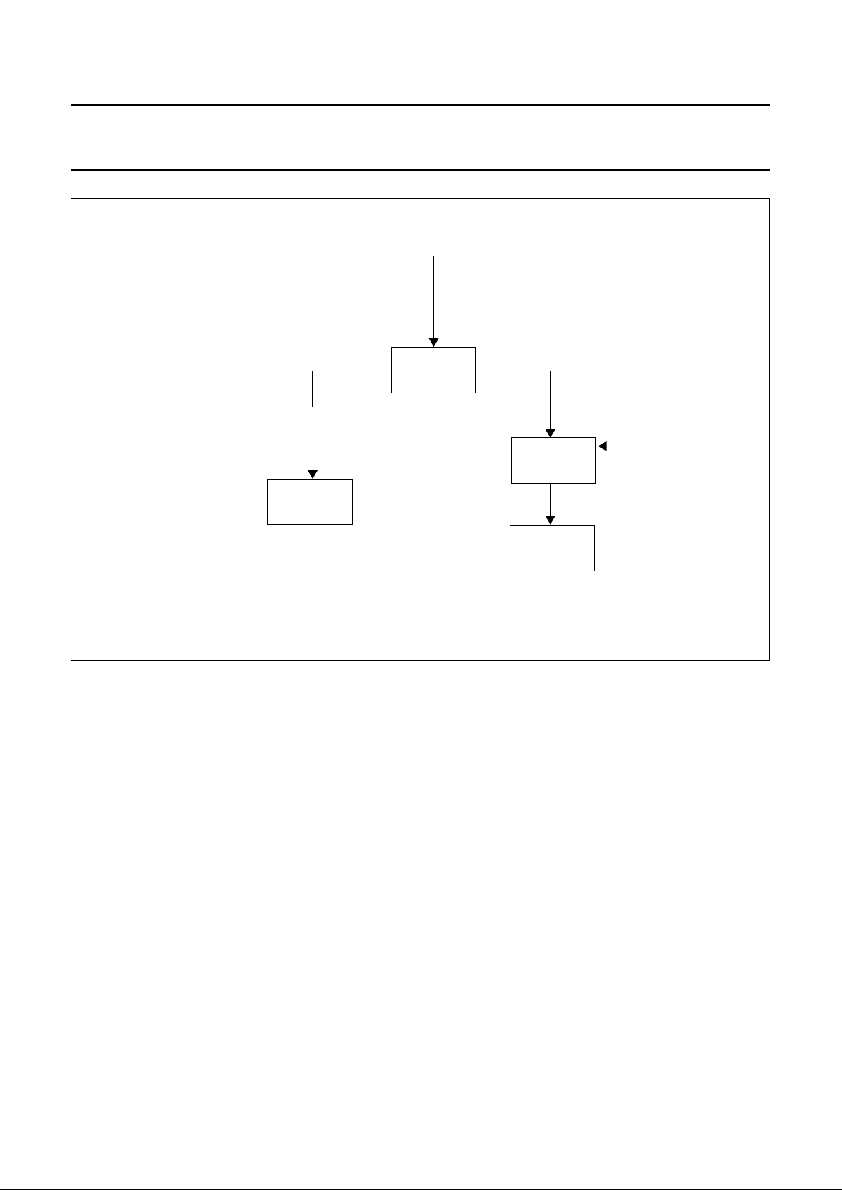
6.2.2 S
After entering the RF-field the transponder waits for a
command to start the authentication.
After issuing this command the mutual authentication
takes place, followed by read- and write commands.
TATUS FLOW
6.2 Operation Modes and Configuration
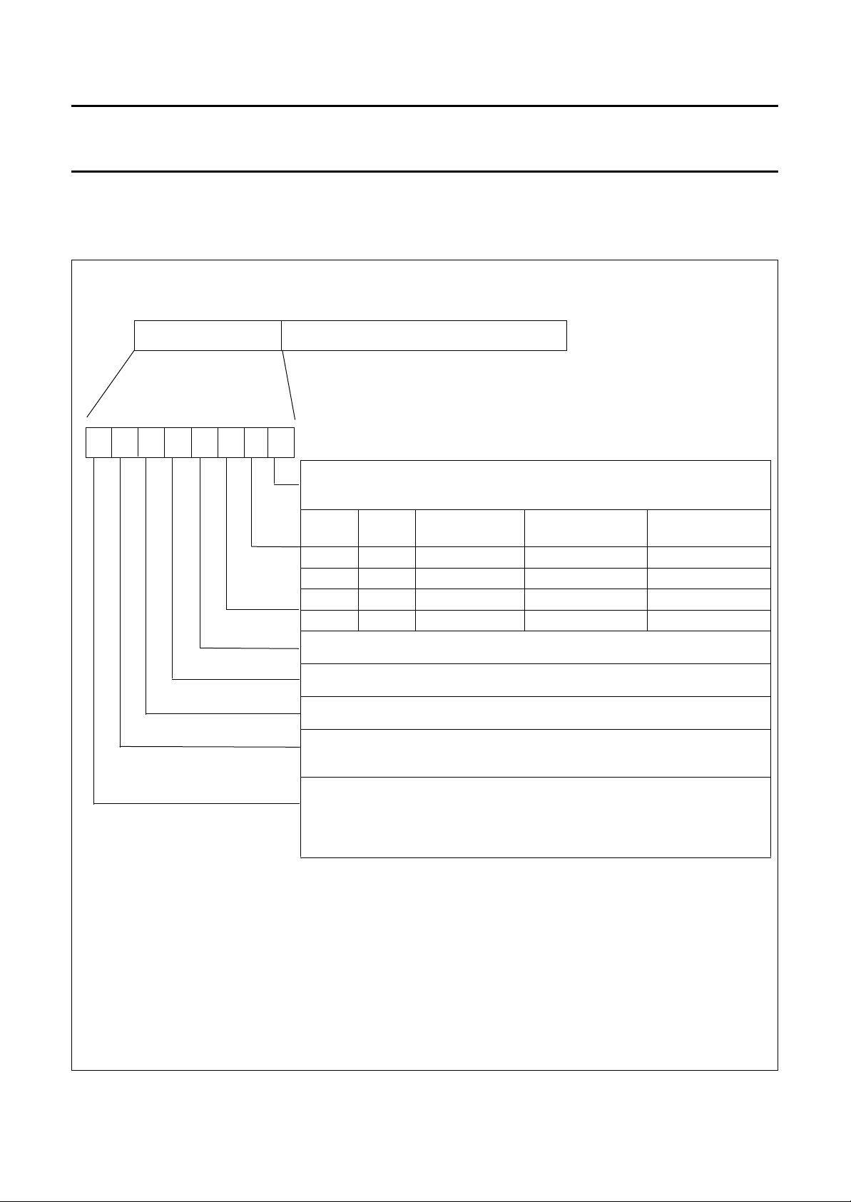
With the Configuration Byte the operation mode and the
access rights to the memory can be selected. During
Power-Up of the transponder the Configuration Byte is
read from the EEPROM of the transponder.
If you change the configuration, keys or passwords, you
have to place the transponder directly on the antenna
(0-distance)! In order to avoid any errors do not move the
transponder during this write process and be sure that you
are in a safe environment without electrical noise.
March 1998 6
In password mode the data transfer occurs plain, in crypto
mode data are encrypted.
The halt mode can be entered for muting a transponder.
If the transponder is configured in one of the public modes,
these modes are entered automatically after a certain
waiting time and data pages are sent cyclically to the
read/write device.
By issuing the command to start the authentication during
the waiting time also public mode transponders can be
brought into the authorized state.
Page 7
Philips Semiconductors Product specification Revision 2.0
HITAGTM2 Transponders
ENTERING PUBLIC MODES
(if configured)
READ-ONLY
RF-FIELD APPLIED
WAIT
START AUTHENTICATION
AUTHORIZED
HALT
HT2 DC20 S20
READ, WRITE
COMMANDS
Fig.2 Status flow.
March 1998 7
Page 8
Philips Semiconductors Product specification Revision 2.0
HITAGTM2 Transponders
6.2.3 CONFIGURATION The Configuration Byte is represented by the first 8 bits of Page 3 of the transponder memory.
PAGE 3
7
BIT 31 BIT 24
CONFIGURATION BYTE
6
5 4 3 2 1 0
BIT 23 BIT0
PASSWORD TAG (24-BIT)
0: Manchester Code (does effect HITAG 2 Operation only)
1: Biphase Code (does effect HITAG 2 Operation only)
BIT 2 BIT 1 VERSION CODING
00
01
10
11
0: password mode
1: crypto mode
0: PAGE 6 and 7 read/write
1: PAGE 6 and 7 read only
0: PAGE 4 and 5 read/write
1: PAGE 4 and 5 read/write
THE SETTING OF THIS BIT IS OTP (One Time Programmable)!
0: PAGE 3 read/write
1: PAGE 3 read only; Configuration Byte and Password TAG fixed
THE SETTING OF THIS BIT IS OTP!
0: PAGE 1 and 2 read/write
1: PAGE 1 no read/no write
PAGE 2 read only (when transponder is in password mode)
PAGE 2 no read/no write (when transponder is in crypto mode)
Public Mode B biphase depending on bit 0
Public Mode A manchester depending on bit 0
Public Mode C biphase depending on bit 0
HITAG 2 depending on bit 0 depending on bit 0
(2)
HT2 DC20 S20
CODING IN HITAG
2- OPERATION
(1)
(1) Do not set Bit 6 of the Configuration Byte to 1 before having written the final data into Page 3
(including the Configuration Byte and Password TAG) of the transponder.
(2) Do not set Bit 7 of the Configuration Byte to 1 before having written the final data into Pages 1
and 2 of the transponder.
Fig.3 Description of configuration byte.
March 1998 8
Page 9

Philips Semiconductors Product specification Revision 2.0
HITAGTM2 Transponders
Table 2 Standard values for the Configuration Byte
NAME VALUE
Password Mode 0x06
Crypto Mode 0x0E
Public Mode A 0x02
Public Mode B 0x00
Public Mode C 0x04
6.3 Configuration of Delivered Transponders
Table 3 Configuration of Delivered Transponders
HT2DC20S20 transponders are delivered with the following configuration:
NAME DESCRIPTION REMARK
Unique Serial Number:
Serial Number Read Only fixed
Configuration Byte:
0x06: Password Mode (Manchester Code) can be changed
Page 6 and 7 read/write
Page 4 and 5 read/write
Page 3 read/write
Page 1 and 2 read/write
HT2 DC20 S20
Values for Transport Passwords, Transport Keys:
Password RWD: 0x4D494B52 (= “MIKR”)
Password TAG: 0xAA4854
Key Low: 0x4D494B52 (= “MIKR”)
Key High: 0x4F4E (= “ON”)
Note
1. Before delivering transponders to end users, Pages 1 to 3 should be locked (set Configuration Byte / Bit 6 to 1 for
Page 3 and set Configuration Byte / Bit 7 to 1 for Pages 1 and 2).
March 1998 9
Page 10

Philips Semiconductors Product specification Revision 2.0
HITAGTM2 Transponders
6.4 Definition of Passwords and Keys
Keys are cryptographic codes, which determine data
encryption during data transfer between read/write device
and transponder. They are used to select a HT2DC20S20
transponder in Crypto Mode. The 16 bit KEY HIGH and 32
bit KEY LOW form one 48 bit key which has to be identical
on both the transponder and the read/write device.
Passwords are needed to select a HT2DC20S20
transponder in Password Mode. There is one pair of
passwords (Password TAG, Password RWD) which has to
be identical both on the transponder and the read/write
device.
• Password TAG:
– Password that the transponder sends to the
read/write device and which may be verified by the
latter (depending on the configuration of the
read/write device).
• Password RWD:
– Password that the read/write device sends to the
transponder and which is checked for identity by the
latter.
HT2 DC20 S20
The passwords and keys are predefined by Philips by
means of defined Transport Passwords and a Transport
Key. They can be written to, which means that they can be
changed (see also Chapter Configuration of Delivered
HT2DC20S20 Transponders).
Note: Passwords and Keys only can be changed if their
current values are known!
It is important that the following values are in accordance
with each other, i.e. the respective data on the read/write
device and on the transponder have to be identical pairs.
Table 4 HT2DC20S20 in Password mode:
ON THE READ/WRITE
DEVICE
Password RWD ⇔ Password RWD
As an option (depending on the configuration of the
read/write device):
Password TAG ⇔ Password TAG
Table 5 HT2DC20S20 in Crypto mode:
ON THE
READ/WRITE
DEVICE
KEY LOW ⇔ KEY LOW
KEY HIGH ⇔ KEY HIGH
As an option (depending on the configuration of the
read/write device):
Password TAG ⇔ Password TAG
ON THE
TRANSPONDER
ON THE
TRANSPONDER
March 1998 10
Page 11

Philips Semiconductors Product specification Revision 2.0
HITAGTM2 Transponders
7 LIMITING VALUES
All values are in accordance with the Absolute Maximum Rating System (IEC 134).
PARAMETER MIN. MAX. UNIT
number of erase/write cycles of the EEPROM 100000
data retention time of the EEPROM 10 years
• @ 55 °C
operating temperature range −40 85 °C
storage temperature range −55 125 °C
magnetic flux density (resistivity against
magnetic pulses)
vibration 10 g
• 10 − 2000 Hz
• 3-axis
• IEC 68-2-6, Test Fc
shock 1500 g
• 3-axis
• IEC 68-2-27, Test Ea
0.2 T
HT2 DC20 S20
March 1998 11
Page 12
Philips Semiconductors Product specification Revision 2.0
HITAGTM2 Transponders
HT2 DC20 S20
8 ELECTRICAL CHARACTERISTICS
T0 = 8 ms (period length for f0 = 125 kHz). All parameters are guaranteed within the temperature range from
= −40°C to +85°C.
T
amb
All parameters are characterized with the SCEMTEC test equipment (STM-1), available from SCEMTEC,
Reichshof-Wenrath, Germany.
SYMBOL PARAMETER CONDITION MIN. MAX. UNIT
f
RES
B
B
W
THR
resonance frequency 121.0 129.0 kHz
bandwidth 2.3 kHz
magnetic flux density,
f
CARRIER
= 125 kHz 35 400
(1)
data transmission from transponder
B
B
B
M
PRG
AUTH
READ
IPRG
magnetic flux density for programming
the EEPROM
magnetic flux density for mutual
authentication
field absorption due to the modulation
of the transponder
modulation index (m) of the base
station for programming and
authentication
m = 0.95
f0 = 125 kHz
t
= 8 T
LOW
0
m = 0.95
f0 = 125 kHz
t
= 8 T
LOW
f
CARRIER
B
FIELD
f
CARRIER
B
FIELD
0
= 125 kHz
=35µT
= 125 kHz
=35µWb/m
pulse width 8 T
35 400
35 400
8 µT
pp
95 100 %
2
0
(1)
(1)
µT
µT
µT
pp
pp
pp
pp
Note
1. Maximum available field strength of the test equipment. Transponder limit has not been characterized.
–()
B
maxBmin
=
m
max
B
B
min
-------------------------------------B
+()
maxBmin
B
readBmaxBmin
–=
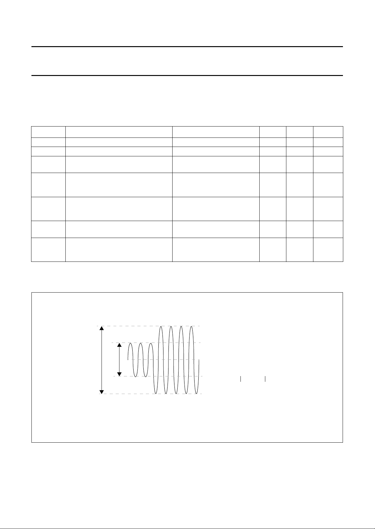
Fig.4 Definition of modulation index.
March 1998 12
Page 13
Philips Semiconductors Product specification Revision 2.0
HITAGTM2 Transponders
HT2 DC20 S20
9 MECHANICAL CHARACTERISTICS
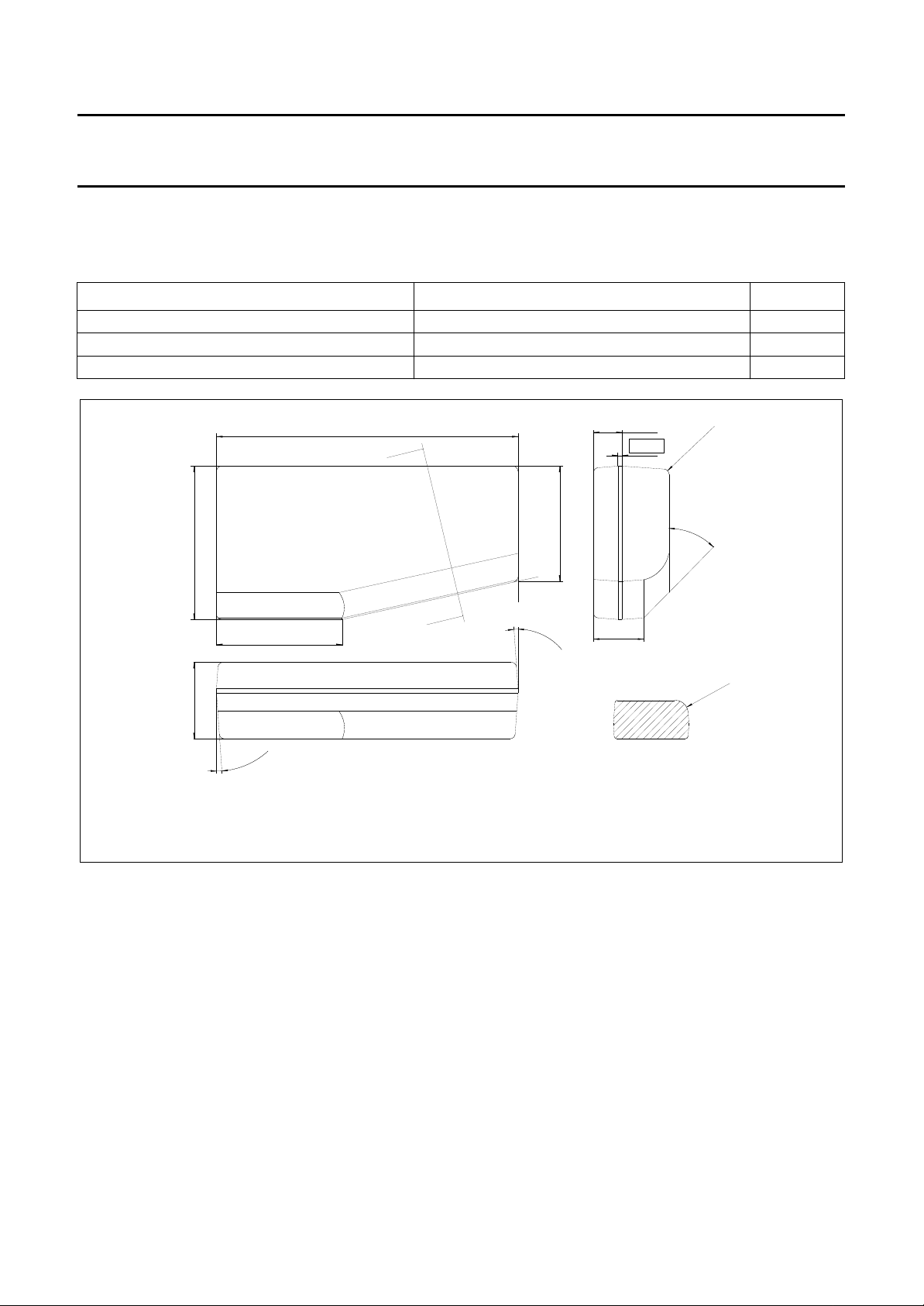
The transponder is sealed in epoxy resin moulding compound. The outline of the package is given in Fig.4. The
designation of the package is SOT385-1.
PARAMETER VALUE UNIT
mechanical dimensions 12 x 6 x 3 mm
protection class IP67
casting material epoxy resin
11.9-12.1
A
4.4 - 4.6
5.9-6.1
1.1-1.2
0.165
R 0.5 max.
all Radii, if not
otherwise specified
44˚-46˚
4.9-5.1
2.9-3.05
0-7˚ (5x)
Protruding plastic must not exceed
specified dimension by more than 0.2 mm
A
0-7˚ (5x)
Fig.5 Package outlines SOT385-1.
1.9-2.1
Cross Section A-A
( without Scale )
R 0.9-1.0
March 1998 13
Page 14

Philips Semiconductors Product specification Revision 2.0
HITAGTM2 Transponders
10 DEFINITIONS
Data sheet status
Objective specification This data sheet contains target or goal specifications for product development.
Preliminary specification This data sheet contains preliminary data; supplementary data may be published later.
Product specification This data sheet contains final product specifications.
Limiting values
Limiting values given are in accordance with the Absolute Maximum Rating System (IEC 134). Stress above one or
more of the limiting values may cause permanent damage to the device. These are stress ratings only and operation
of the device at these or at any other conditions above those given in the Characteristics sections of the specification
is not implied. Exposure to limiting values for extended periods may affect device reliability.
Application information
Where application information is given, it is advisory and does not form part of the specification.
11 LIFE SUPPORT APPLICATIONS
These products are not designed for use in life support appliances, devices, or systems where malfunction of these
products can reasonably be expected to result in personal injury. Philips customers using or selling these products for
use in such applications do so on their own risk and agree to fully indemnify Philips for any damages resulting from such
improper use or sale.
HT2 DC20 S20
March 1998 14
Page 15

Philips Semiconductors Product specification Revision 2.0
HITAGTM2 Transponders
HT2 DC20 S20
NOTES
March 1998 15
Page 16

Philips Semiconductors – a worldwide company
Argentina: see South America
Australia: 34 Waterloo Road, NORTH RYDE, NSW 2113,
Tel. +61 2 9805 4455, Fax. +61 2 9805 4466
Austria: Computerstr. 6, A-1101 WIEN, P.O. Box 213, Tel. +43 160 1010,
Fax. +43 160 101 1210
Belarus: Hotel Minsk Business Center, Bld. 3, r. 1211, Volodarski Str. 6,
220050 MINSK, Tel. +375 172 200 733, Fax. +375 172 200 773
Belgium: see The Netherlands
Brazil: seeSouth America
Bulgaria: Philips Bulgaria Ltd., Energoproject, 15thfloor,
51 James Bourchier Blvd., 1407 SOFIA,
Tel. +359 2 689 211, Fax. +359 2 689 102
Canada: PHILIPS SEMICONDUCTORS/COMPONENTS,
Tel. +1 800 234 7381
China/Hong Kong: 501 Hong Kong Industrial Technology Centre,
72 Tat Chee Avenue, Kowloon Tong, HONG KONG,
Tel. +852 2319 7888, Fax. +852 2319 7700
Colombia: see South America
Czech Republic: see Austria
Denmark: Prags Boulevard 80, PB 1919, DK-2300 COPENHAGEN S,
Tel. +45 32 88 2636, Fax. +45 31 57 0044
Finland: Sinikalliontie 3, FIN-02630 ESPOO,
Tel. +358 9 615800, Fax. +358 9 61580920
France: 4 Rue du Port-aux-Vins, BP317, 92156 SURESNES Cedex,
Tel. +33 1 40 99 6161, Fax. +33 1 40 99 6427
Germany: Hammerbrookstraße 69, D-20097 HAMBURG,
Tel. +49 40 23 53 60, Fax. +49 40 23 536 300
Greece: No. 15, 25th March Street, GR 17778 TAVROS/ATHENS,
Tel. +30 1 4894 339/239, Fax. +30 1 4814 240
Hungary: seeAustria
India: Philips INDIA Ltd, Band Box Building, 2nd floor,
254-D, Dr. Annie Besant Road, Worli, MUMBAI 400 025,
Tel. +91 22 493 8541, Fax. +91 22 493 0966
Indonesia: see Singapore
Ireland: Newstead, Clonskeagh, DUBLIN 14,
Tel. +353 1 7640 000, Fax. +353 1 7640 200
Israel: RAPAC Electronics, 7 Kehilat SalonikiSt, PO Box 18053,
TEL AVIV 61180, Tel. +972 3 645 0444, Fax. +972 3 649 1007
Italy: PHILIPS SEMICONDUCTORS, Piazza IV Novembre 3,
20124 MILANO, Tel. +39 2 6752 2531, Fax. +39 2 6752 2557
Japan: Philips Bldg 13-37, Kohnan 2-chome, Minato-ku, TOKYO 108,
Tel. +81 3 3740 5130, Fax. +81 3 3740 5077
Korea: Philips House, 260-199 Itaewon-dong, Yongsan-ku, SEOUL,
Tel. +82 2 709 1412, Fax. +82 2 709 1415
Malaysia: No. 76 Jalan Universiti, 46200 PETALING JAYA, SELANGOR,
Tel. +60 3 750 5214, Fax. +60 3 757 4880
Mexico: 5900 Gateway East, Suite 200, EL PASO, TEXAS 79905,
Tel. +9-5 800 234 7381
Middle East: see Italy
Netherlands: Postbus 90050, 5600PB EINDHOVEN, Bldg. VB,
Tel. +31 40 27 82785, Fax. +31 40 27 88399
New Zealand: 2 Wagener Place, C.P.O. Box1041, AUCKLAND,
Tel. +64 9 849 4160, Fax. +64 9 849 7811
Norway: Box 1, Manglerud 0612, OSLO,
Tel. +47 22 74 8000, Fax. +47 22 74 8341
Philippines: Philips Semiconductors Philippines Inc.,
106 Valero St. Salcedo Village, P.O. Box2108 MCC, MAKATI,
Metro MANILA, Tel. +63 2 816 6380, Fax. +63 2 817 3474
Poland: Ul. Lukiska 10, PL 04-123 WARSZAWA,
Tel. +48 22 612 2831, Fax. +48 22 612 2327
Portugal: see Spain
Romania: see Italy
Russia: Philips Russia, Ul. Usatcheva 35A, 119048 MOSCOW,
Tel. +7 095 755 6918, Fax. +7 095 755 6919
Singapore: Lorong 1, Toa Payoh, SINGAPORE 1231,
Tel. +65 350 2538, Fax. +65 251 6500
Slovakia: see Austria
Slovenia: see Italy
South Africa: S.A. PHILIPS Pty Ltd., 195-215 Main Road Martindale,
2092 JOHANNESBURG, P.O. Box 7430 Johannesburg 2000,
Tel. +27 11 470 5911, Fax. +27 11 470 5494
South America: Rua do Rocio 220, 5th floor, Suite 51,
04552-903 São Paulo, SÃO PAULO - SP, Brazil,
Tel. +55 11 821 2333, Fax. +55 11 829 1849
Spain: Balmes 22, 08007 BARCELONA,
Tel. +34 3 301 6312, Fax. +34 3 301 4107
Sweden: Kottbygatan 7, Akalla, S-16485 STOCKHOLM,
Tel. +46 8 632 2000, Fax. +46 8 632 2745
Switzerland: Allmendstrasse 140, CH-8027 ZÜRICH,
Tel. +41 1 488 2686, Fax. +41 1 481 7730
Taiwan: Philips Semiconductors, 6F, No. 96, Chien Kuo N. Rd., Sec. 1,
TAIPEI, Taiwan Tel. +886 2 2134 2865, Fax. +886 2 2134 2874
Thailand: PHILIPS ELECTRONICS (THAILAND) Ltd.,
209/2 Sanpavuth-Bangna Road Prakanong, BANGKOK 10260,
Tel. +66 2 745 4090, Fax. +66 2 398 0793
Turkey: Talatpasa Cad. No. 5, 80640 GÜLTEPE/ISTANBUL,
Tel. +90 212 279 2770, Fax. +90 212 282 6707
Ukraine: PHILIPS UKRAINE, 4 Patrice Lumumba str., Building B, Floor 7,
252042 KIEV, Tel. +380 44 264 2776, Fax. +380 44 268 0461
United Kingdom: Philips Semiconductors Ltd., 276 Bath Road, Hayes,
MIDDLESEX UB3 5BX, Tel. +44 181 730 5000, Fax. +44 181 754 8421
United States: 811 East Arques Avenue, SUNNYVALE, CA 94088-3409,
Tel. +1 800 234 7381
Uruguay: see South America
Vietnam: see Singapore
Yugoslavia: PHILIPS, Trg N. Pasica 5/v, 11000 BEOGRAD,
Tel. +381 11 625 344, Fax.+381 11 635 777
For all other countries apply to: Philips Semiconductors, Marketing & Sales Communications,
Building BE-p, P.O. Box 218, 5600 MD EINDHOVEN, The Netherlands, Fax. +31 40 27 24825
© Philips Electronics N.V. 1997 SCA55
All rights are reserved. Reproduction in whole or in part is prohibited without the prior written consent of the copyright owner.
The information presented in this document does not form part of any quotation or contract, is believed to be accurate and reliable and may be changed
without notice. No liability will be accepted by the publisher for any consequence of its use. Publication thereof does not convey nor imply any license
under patent- or other industrial or intellectual property rights.
Internet: http://www.semiconductors.philips.com
 Loading...