

Page 1

Am29F800B
8 Megabit (1 M x 8-Bit/512 K x 16-Bit)
CMOS 5.0 Volt-only, Boot Sector Flash Memory
DISTINCTIVE CHARACTERISTICS
■ Single power supply operation
— 5.0 Volt-only operation for read, erase, and
program operations
— Minimizes system level requirements
■ Manufactured on 0.32 µm process technology
— Compatible with 0.5 µm Am29F800 device
■ High performance
— Access times as fast as 55 ns
■ Low power consumption (typical values at
5MHz)
— 1 µA standby mode current
— 20 mA read current (byte mode)
— 28 mA read current (word mode)
— 30 mA program/erase current
■ Embedded Al gorithms
— Embedded Erase algorithm automatically
preprograms and erases the entire chip or any
combination of designated sectors
— Embedded Program algorithm automatically
writes and verifies data at specified addresses
■ Minimum 1,000,000 progr am/erase cycles per
sector guaranteed
■ 20-year data retention at 125°C
— Reliable operation for the life of the system
■ Package option
— 48-pin TSOP
— 44-pin SO
— Known Good Die (KGD)
(see publication number 21631)
■ Flexible sector architecture
— One 16 Kbyte, two 8 Kbyte, one 32 Kbyte, and
fifteen 64 Kbyte sectors (byte mode)
— One 8 Kword, two 4 Kword, one 16 Kword, and
fifteen 32 Kword sectors (word mode)
— Supports full chip erase
— Sector Protection features:
A hardware method of locking a sector to
prevent any program or erase operations within
that sector
— Sectors can be locked via programming
equipment
T emporary Sector Unprotect feat ure allows code
changes in previously locked sectors
■ Top or bottom boot block configurations
available
■ Compatibility with JEDEC standards
— Pinout and software compatible with single-
power-supply Flash
— Superior inadvertent write protection
■ Data# Polling and toggle bits
— Provides a software method of detecting
program or erase operation completion
■ Ready/Busy# pin (RY/BY#)
— Provides a hardware method of detecting
program or erase cycle completion
■ Erase Suspend/Erase Resume
— Suspends an erase operati on to read dat a from,
or program data to, a sector that is not being
erased, then resumes the erase operation
■ Hardware reset pin (RESET#)
— Hardware method to reset the de vice t o reading
array data
This Data Sheet states AMD’s current technical specifications regarding the Product described herein. This Data
Sheet may be revised by subsequent versions or modifications due to changes in technical specifications.
Publication# 21504 Rev: D Amendment/+2
Issue Date: July 2, 1999
Page 2

GENERAL DESCRIPTION
The Am29F800B is an 8 Mbit, 5.0 volt-only Flas h
memory organized as 1,048,576 bytes or 524,288
words. The device is offered in 44-pin SO and 48-pin
TSOP packages. The device is also available in Known
Good Die (KGD) form. For more infor mation, refer to
publication number 21631. T he word-wide data (x16 )
appears on DQ 15–DQ0; the byte-wide (x8) data
appears on DQ7–DQ0. This device is designed to be
programmed in-system with the standard system 5.0
volt V
or erase operations . The device can also be programmed in standard EPROM programmers.
This device is manufactured using AMD’s 0.32 µm
process technology, and offers all the f eatures and benefits of the Am29F800, which was manufactured using
0.5 µm process technology.
The standard device offers access times of 55, 70, 90,
120, and 150 ns, allowing high speed microprocessors
to operate without wai t states . To eliminate b us contention the device has separate chip enable (CE#), write
enable (WE#) and output enable (OE#) controls.
The device requires only a single 5. 0 v o lt po wer sup-
ply for both read and write functions. Internally generated and regulated voltages are provided for the
program and erase operations.
The device is entirely command set compatible with the
JEDEC single-power-supply Flash standard. Commands are written to the command register using standard microproc essor write timing s. Register contents
serve as input to an internal sta te-machine that co ntrols the erase and programming circuit ry. Write cycles
also internally latch addresses and data needed f or the
programming and erase operations. Reading data out
of the device is similar to reading from other Flash or
EPROM devices.
Device programming occurs by executing the program
command sequence. This initiates the Embedded
Program algorithm—an internal algorithm that automatically times the program pulse widths and verifies
proper cell margin.
Device erasure occurs by executing the erase command sequence. This initiates the Embedded Erase
supply. A 12.0 V VPP is not required for write
CC
algorithm—an in ternal algorithm that auto matically
preprograms the arra y (if it is not already progr ammed)
before e xecuting the er ase operation. During erase, the
device automatically tim es the erase pulse widths and
verifies proper cell margin.
The host system can detect whether a program or
erase operation is complete by observing the RY/BY#
pin, or by reading the DQ7 (Data# Polling) and DQ6
(toggle) status bits. After a program or erase cycle has
been completed, the device is ready to read array data
or accept another command.
The sector erase archite cture allo ws m emory sect ors
to be erased and reprogrammed without affecting the
data contents of other sectors. The device is fully
erased when shipped from the factory.
Hardware data protection meas ures include a low
detector that automatically in hibits write opera-
V
CC
tions during power transitions. The hardware sector
protection feature disables both program and erase
operations in any combination of the sectors of memory . This can be achie v ed via prog ramming equipment.
The Erase Suspend feature enables the user to put
erase on hold for any period of time to read data from,
or program data to, any sector that is not selected for
erasure. True background erase can thus be achieved.
The hardware RESET# pi n terminates any operation
in progress and resets the internal state machine to
reading array dat a. The RESET# pin ma y be tied to the
system reset circuitry. A system reset would thus also
reset the device, enabling the system microprocessor
to read the boot-up firmware from the Flash memory.
The system can place the device into the standby
mode. Power consumption is greatly reduced in
this mode.
AMD’s Flash technology combines years of Flash
memory manufacturing experience to produce the
highest levels of quality, reliability and cost effectiveness. The device electrically erases all bi t s w i th i n a
s ect or simultaneously via Fowler-Nordh eim tunneling.
The data is programmed using hot electron injection.
2 Am29F800B
Page 3
PRODUCT SELECTOR GUIDE
Family Part Number Am29F800B
Speed Option V
Max access time, ns (t
ACC
Max CE# access time, ns (t
Max OE# access time, ns (t
= 5.0 V ± 10% -55 -70 -90 -120 -150
CC
) 55 70 90 120 150
) 55 70 90 120 150
CE
) 3030355055
OE
Note: See “AC Characteristics” for full specifications.
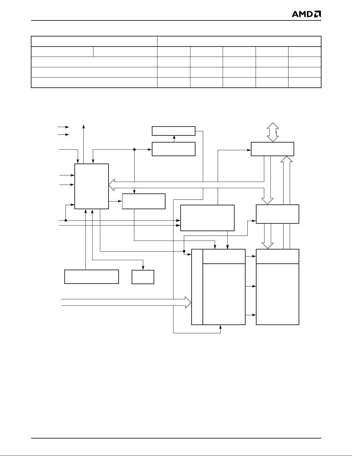
BLOCK DIAGRAM
RY/BY#
V
CC
V
SS
RESET#
WE#
BYTE#
CE#
OE#
State
Control
Command
Register
PGM Voltage
Generator
Sector Switches
Erase Voltage
Generator
Chip Enable
Output Enable
Logic
STB
–
DQ15 (A-1)
DQ0
Input/Output
Buffers
Latch
Data
A0–A18
VCC Detector
Timer
STB
Address Latch
Y-Decoder
X-Decoder
Y-Gating
Cell Matrix
21504D-1
Am29F800B 3
Page 4
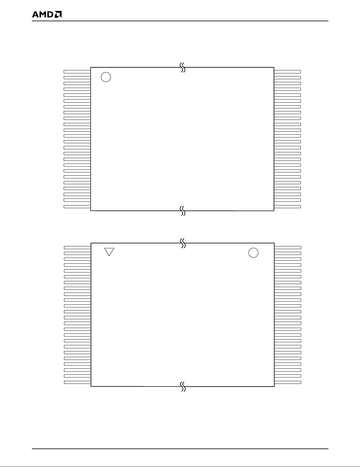
CONNECTION DIAGRAMS
This device is also available in Known Good Die (KGD) form. Refer to publication number 21631 for
more information.
A15
A14
A13
A12
A11
A10
A9
A8
NC
NC
WE#
RESET#
NC
NC
RY/BY#
A18
A17
A7
A6
A5
A4
A3
A2
A1
A16
BYTE#
V
SS
DQ15/A-1
DQ7
DQ14
DQ6
DQ13
DQ5
DQ12
DQ4
V
CC
DQ11
DQ3
DQ10
DQ2
DQ9
DQ1
DQ8
DQ0
OE#
V
SS
CE#
A0
1
2
3
4
5
6
7
8
9
10
11
12
13
14
15
16
17
18
19
20
21
22
23
24
1
2
3
4
5
6
7
8
9
10
11
12
13
14
15
16
17
18
19
20
21
22
23
24
48-Pin TSOP—Standard Pinout
48-Pin TSOP—Reverse Pinout
48
47
46
45
44
43
42
41
40
39
38
37
36
35
34
33
32
31
30
29
28
27
26
25
48
47
46
45
44
43
42
41
40
39
38
37
36
35
34
33
32
31
30
29
28
27
26
25
A16
BYTE#
V
SS
DQ15/A-1
DQ7
DQ14
DQ6
DQ13
DQ5
DQ12
DQ4
V
CC
DQ11
DQ3
DQ10
DQ2
DQ9
DQ1
DQ8
DQ0
OE#
V
SS
CE#
A0
A15
A14
A13
A12
A11
A10
A9
A8
NC
NC
WE#
RESET#
NC
NC
RY/BY#
A18
A17
A7
A6
A5
A4
A3
A2
A1
4 Am29F800B
21504D-2
Page 5
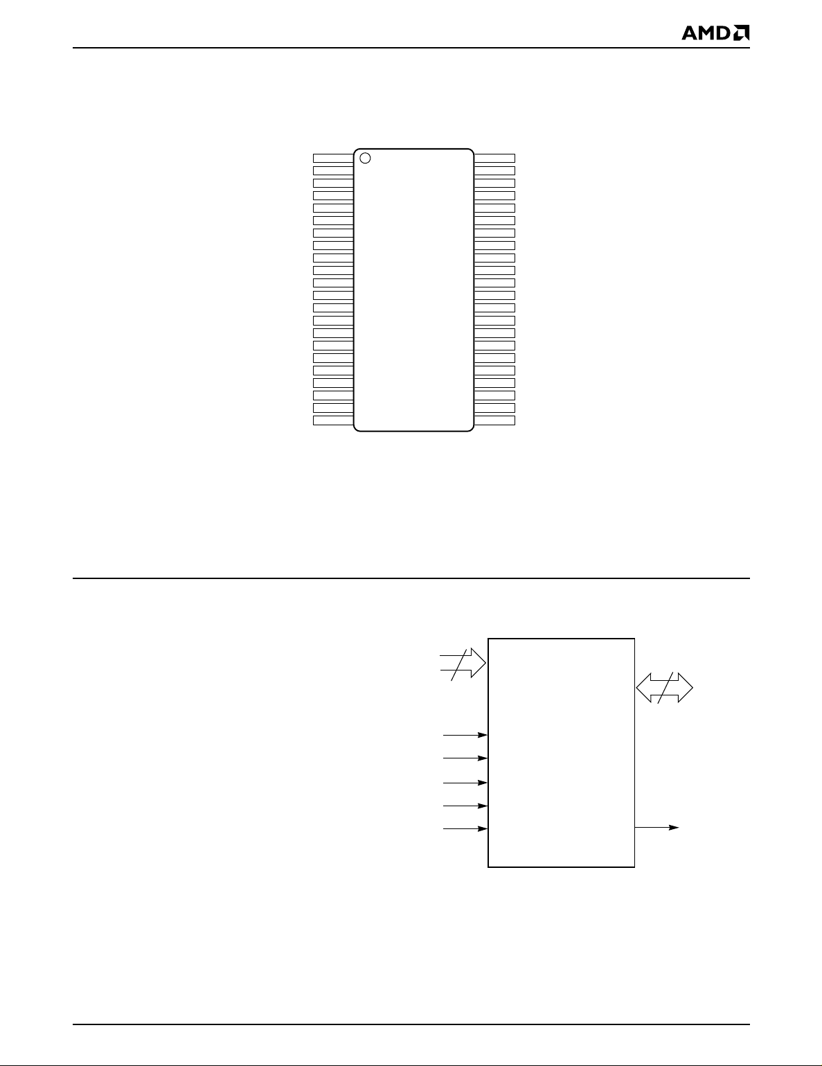
CONNECTION DIAGRAMS
This device is also available in Known Good Die (KGD) form. Refer to publication number 21631 for
more information.
RY/BY#
A18
A17
A7
A6
A5
A4
A3
A2
A1
A0
CE#
V
SS
OE#
DQ0
DQ8
DQ1
DQ9
DQ2
DQ10
DQ3
DQ11
10
11
12
13
14
15
16
17
18
19
20
21
22
1
2
3
4
5
6
7
8
9
SO
44
43
42
41
40
39
38
37
36
35
34
33
32
31
30
29
28
27
26
25
24
23
RESET#
WE#
A8
A9
A10
A11
A12
A13
A14
A15
A16
BYTE#
V
SS
DQ15/A-1
DQ7
DQ14
DQ6
DQ13
DQ5
DQ12
DQ4
V
CC
21504D-3
PIN CONFIGURATION
A0–A18 = 19 addresses
DQ0–DQ14 = 15 data inputs/outputs
DQ15/A-1 = DQ15 (data input/output, word mode),
A-1 (LSB address input, byte mode)
BYTE# = Selects 8-bit or 16-bit mode
CE# = Chip enable
OE# = Output enable
WE# = Write enable
RESET# = Hardware reset pin, active low
RY/BY# = Ready/Busy# output
= +5.0 V single power supply
V
CC
V
SS
NC = Pin not connected internally
(see Product Selector Guide for
device speed ratings and voltage
supply tolerances)
= Device ground
LOGIC SYMBOL
19
A0–A18
CE#
OE#
WE#
RESET#
BYTE# RY/BY#
16 or 8
DQ0–DQ15
(A-1)
21504D-4
Am29F800B 5
Page 6
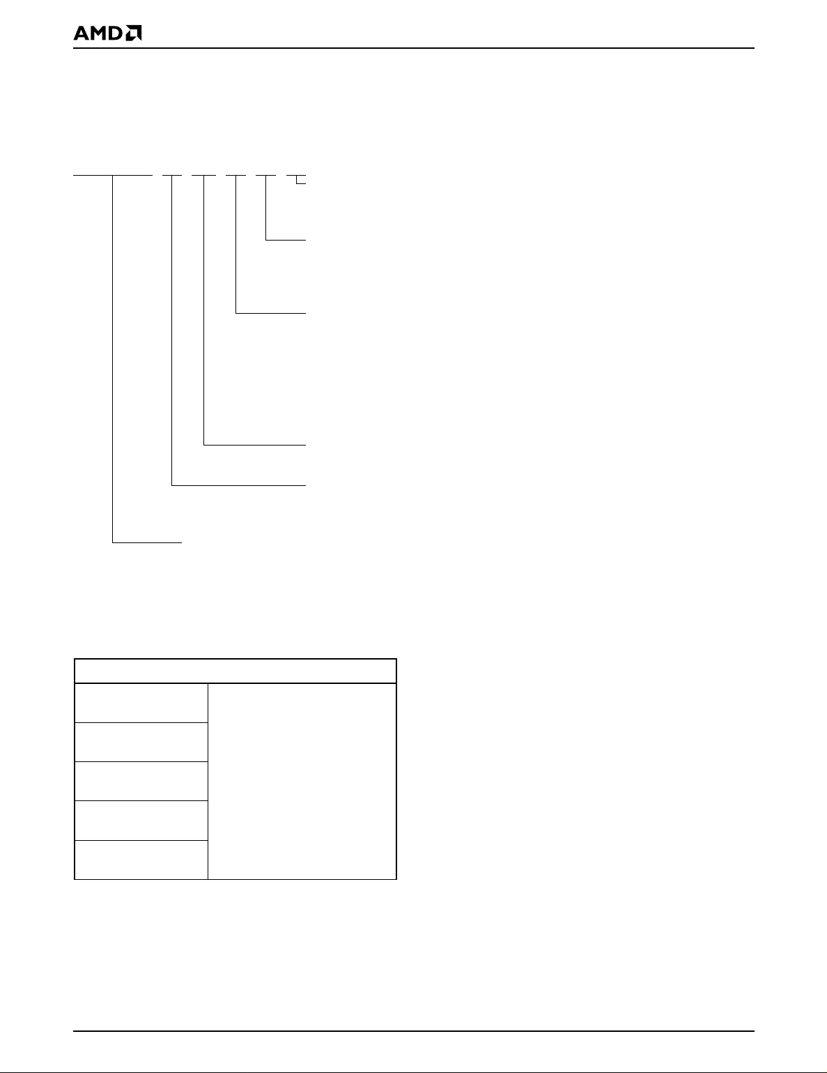
ORDERING INFORMATION
Standard Pr od ucts
AMD standard products are available in several packages and operating ranges. The order number (Valid Combination) is formed
by a combination of the elements below.
Am29F800B T -70 E C
OPTIONAL PROCESSING
Blank = Standard Processing
(Contact an AMD representative for more information)
TEMPERATURE RANGE
C=Commercial (0°C to +70°C)
I = Industrial (–40
E = Extended (–55
PACKAGE TYPE
E = 48-Pin Thin Small Outline Package (TSOP)
Standard Pinout (TS 048)
F = 48-Pin Thin Small Outline Package (TSOP)
Reverse Pinout (TSR048)
S = 44-Pin Small Outline Package (SO 044)
This device is also available in Known Good Die (KGD) form. See publication number
21536 for more information.
SPEED OPTION
See Product Selector Guide and Valid Combinations
°C to +85°C)
°C to +125°C)
AM29F800BT-55,
AM29F800BB-55
AM29F800BT-70,
AM29F800BB-70
AM29F800BT-90,
AM29F800BB-90
AM29F800BT-120,
AM29F800BB-120
AM29F800BT-150,
AM29F800BB-150
BOOT CODE SECTOR ARCHITECTURE
T = Top sector
B = Bottom sector
DEVICE NUMBER/DESCRIPTION
Am29F800B
8 Megabit (1 M x 8-Bit/512K x 16-Bit) CMOS Flash Memory
5.0 Volt-only Read, Program and Erase
Valid Combinations
Valid Combinations list configurations planned to be supported in volume for this device. Consult the local AMD sales
office to confirm availability of specific valid combinations and
to check on newly released combinations.
EC, EI, EE,
FC, FI, FE,
SC, SI, SE
Valid Combinations
6 Am29F800B
Page 7
DEVICE BUS OPERATIONS
This section describes the requirements and use of the
device bus operations, which are initiated through the
internal c ommand register. The command register itself does not occupy any addressable memory location. The register is composed of l atches that store the
commands, along with the address and data information needed to execute the command. The contents of
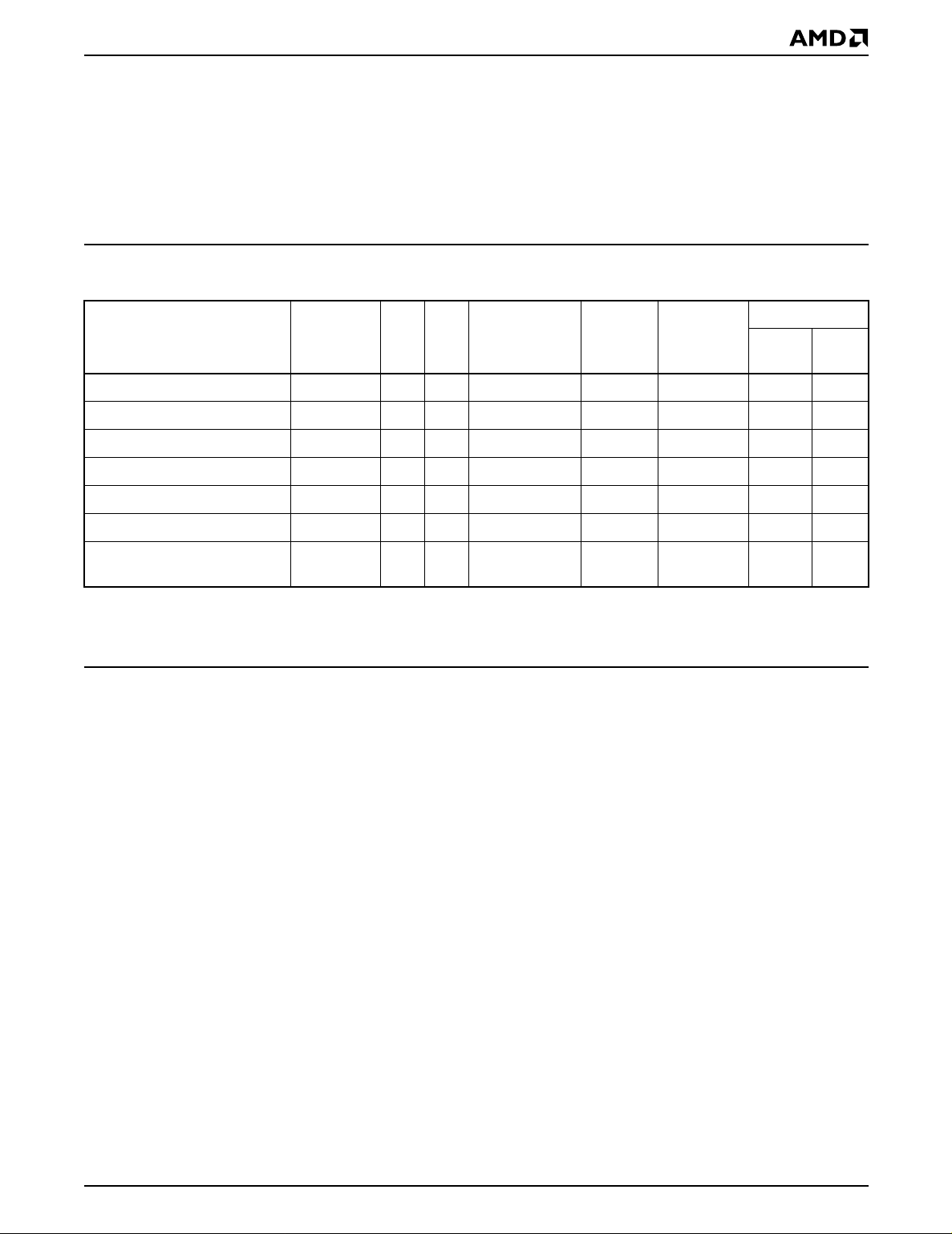
Table 1. Am29F800B Device Bus Operations
the register serve as inputs to the internal state machine. The state machine outputs dictate the function of
the device. The appropriate device bus operations
table lists the inputs and control le vels requ ired, and the
resulting output. The following subsections describe
each of these operations in further detail.
DQ8–DQ15
OUT
D
D
BYTE#
= V
IH
High-Z
High-Z
IN
IN
X
BYTE#
Operation CE# OE# WE# RESET# A0–A18 DQ0–DQ7
Read L L H H A
Write L H L H A
CMOS Standby V
TTL Standby H X X H X High-Z High-Z High-Z
Output Disable L H H H X High-Z High-Z High-Z
Hardware Reset X X X L X High-Z High-Z High-Z
Temporary Sector Unprotect
(See Note)
Legend:
L = Logic Low = V
Note: See the sections on Sector Group Protection and Temporary Sector Unprotect for more information.
, H = Logic High = VIH, VID = 12.0 ± 0.5 V, X = Don’t Care, DIN = Data In, D
IL
Word/Byte Configuration
The BYTE# pin controls whether the device data I/O
pins DQ15–DQ0 operate in the by te or word configur ation. If the BYTE# pin is set at logic ‘1’, the device is in
word configuration, DQ15–DQ0 are active and controlled by CE# and OE#.
If the BYTE# pin is set at logic ‘0’, the device is in byte
configuration, and only data I/O pins DQ0–DQ7 are active and controlled by CE# and OE#. The data I/O pins
DQ8–DQ14 are tri-stated, and the DQ15 pin is used as
an input for the LSB (A-1) address function.
± 0.5 V X X VCC ± 0.5 V X High-Z High-Z High-Z
CC
XXX V
ID
command is necessar y in this mode to obtain array
data. Standard microprocessor read cycles that assert valid addresses on the device address inputs
produce valid data on the device data outputs. The
device remains enabled for read access until the
command register contents are altered.
See “Reading Array Data” for more information. Refer
to the AC Read Operations table for timing specifications and to the Read Operations Timings diagram for
the timing waveforms. I
table represents the active current specification for
reading array data.
IN
IN
A
IN
D
OUT
D
IN
D
IN
= Data Out, AIN = Address In
OUT
in the DC Characteristics
CC1
= V
D
IL
Requirements for Reading Array Data
To read array data from the outputs, the system must
drive the CE# and OE# pins to V
control and selects the device. OE# is the output control
and gates array data to the output pins. WE# should remain at V
.
IH
The internal state machin e is set for reading array
data upon device power-up, or after a hardware reset.
This ensures that no spurious alteration of the memory content occurs during the power transition. No
. CE# is the power
IL
Am29F800B 7
Writing Commands/Command Sequences
To write a command or command sequence (which includes programming data to the device and erasing
sectors of memory), the system must drive WE# and
CE# to V
An erase operation can erase one sect or, multiple sectors, or the entire de vice. The Sector Address Tables indicate the address space that each sector occupies. A
“sector address” consists of the address bits required
to uniquely select a sector. See the “Command Defini-
, and OE# to VIH.
IL
Page 8

tions” section for details on erasing a sector or the en-
tire chip, or suspending/resuming the erase operation.
In the DC Characteristics tables, I
standby current specification.
represents the
CC3
After the system writes the autoselect command sequence, the device enters the autoselect mode. The
system can then read autoselect codes from the internal register (which is separate from the memory array)
on DQ7–DQ0. Standard read cycle timings apply in this
mode. Refer to the “Autoselect Mode” and “Autoselect
Command Sequence” sections for more information.
in the DC Characteristics table represents the ac-
I
CC2
tive current specification for the write mode. The “AC
Characteristics” section contains timing specification
tables and timing diagrams for write operations.
Program and Erase Operation Status
During an erase or program operation, the system ma y
check the status of the operation by reading the status
bits on DQ7–DQ0. Standard read cycle timings and I
CC
read specifications apply. Refer to “Write Operation
Status” for more information, and to each AC Characteristics section for timing diagrams.
Standby Mode
When the system is not reading or writing to the device ,
it can place the device in the standby mode. In this
mode, current consumption is great ly reduc ed, and the
outputs are placed in the high impedance state, independent of the OE# input.
The device enters the CMOS standby mode when CE#
and RESET# pins are both held at V
that this is a more restrict ed voltage range than V
The device enters the TTL standby mode when CE#
and RESET# pins are both held at V
quires standard access time (t
) for read access when
CE
the device is in either of these standb y modes, bef ore it
is ready to read data.
The device also enters the standb y mode when the RESET# pin is driven low. Refer to the next section, “RESET#: Hardware Reset Pin”.
If the device is deselected during erasure or programming, the device draws active current until the
operation is completed.
± 0.5 V. (Note
CC
. The device re-
IH
IH
RESET#: Hardware Reset Pin
The RESET# pin provides a hardw are method of resetting the device to readin g arr ay data. When the system
drives the RESET# pin low for at least a period of t
the device immediately terminates any operation in
progress, tristates all data output pins, and ignores all
read/write attempts for the duration o f the RESET#
pulse. The device also resets the inter nal state machine to reading array data. The operation that was interrupted should be reinitiated once the device is ready
to accept another command sequence, to ensure data
integrity.
Current is reduced for the duration of the RESET#
pulse. When RESET# is held at V
, the device enters
IL
the TTL standby mode; if RESET# is held at V
0.5 V, the device enters the CMOS standby mode.
The RESET# pin may be tied to the system reset cir-
cuitry. A system reset would thus also reset the Flash
memory, enabling the system to read the boot-up firmware from the Flash memory.
If RESET# is asserted during a program or erase operation, the RY/BY# pin remains a “0” (busy) until the internal reset operatio n is complete, which requires a
time of t
(during Embedded Algorithms). The
READY
system can thus monitor RY/BY# to determine whether
the reset operation is complete. If RESET# is asserted
when a program or erase operation is not executing
(RY/BY# pin is “1”), the reset operation is completed
.)
within a time of t
rithms). The system can read data t
SET# pin returns to V
(not during Embe dded Algo-
READY
.
IH
RH
Refer to the AC Characteristics tables for RESET# parameters and timing diagram.
Output Disable Mode
When the OE# input is at VIH, output from the device is
disabled. The output pins are placed in t he high impedance state.
RP
SS
after the RE-
,
±
8 Am29F800B
Page 9
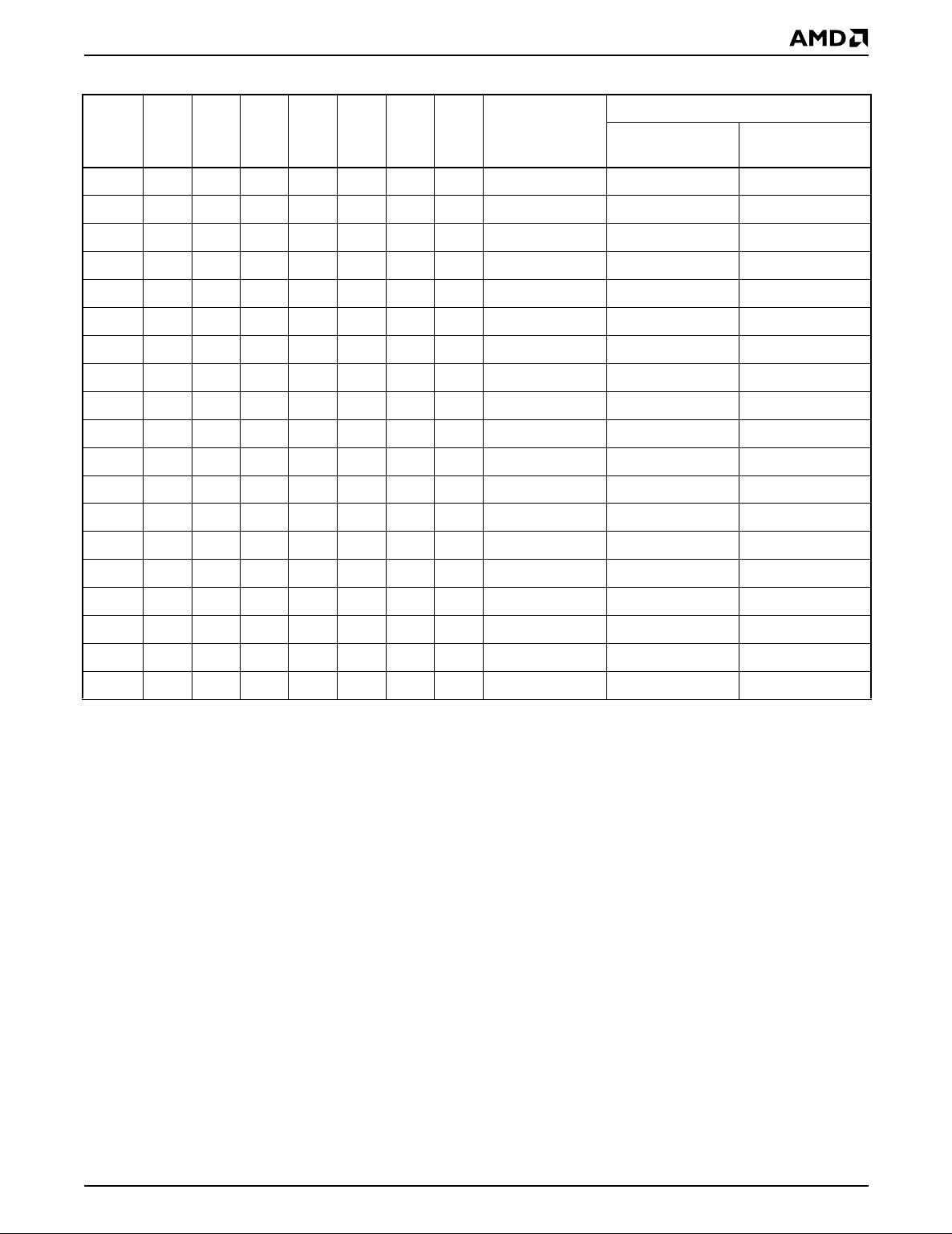
Table 2. Am29F800BT Top Boot Block Sector Address Table
Sector Size
(Kbytes/
Sector A18 A17 A16 A15 A14 A13 A12
SA0 0 0 0 0 X X X 64/32 00000h–07FFFh 00000h–0FFFFh
SA1 0 0 0 1 X X X 64/32 08000h–0FFFFh 10000h–1FFFFh
SA2 0 0 1 0 X X X 64/32 10000h–17FFFh 200 00h –2F FF Fh
SA3 0 0 1 1 X X X 64/32 18000h–1FFFFh 30000h–3FFFFh
SA4 0 1 0 0 X X X 64/32 20000h–27FFFh 400 00h –4F FF Fh
SA5 0 1 0 1 X X X 64/32 28000h–2FFFFh 50000h–5FFFFh
SA6 0 1 1 0 X X X 64/32 30000h–37FFFh 600 00h –6F FF Fh
SA7 0 1 1 1 X X X 64/32 38000h–3FFFFh 70000h–7FFFFh
SA8 1 0 0 0 X X X 64/32 40000h–47FFFh 800 00h –8F FF Fh
SA9 1 0 0 1 X X X 64/32 48000h–4FFFFh 90000h–9FFFFh
SA10 1 0 1 0 X X X 64/32 50000h–57FFFh A 00 00h –A FFF Fh
SA11 1 0 1 1 X X X 64/32 58000h–5FFFFh B0000h–BFFF Fh
SA12 1 1 0 0 X X X 64/32 60000h–67FFFh C0000h–CFFF Fh
SA13 1 1 0 1 X X X 64/32 68000h–6FFFFh D 00 00h –D FFF Fh
Kwords)
Address Range (in hexadecimal)
(x16)
Address Range
(x8)
Address Range
SA14 1 1 1 0 X X X 64/32 70000h–77FFFh E 00 00h –E FFF Fh
SA15 1 1 1 1 0 X X 32/16 78000h– 7B FFF h F0000h–F7FFFh
SA16 1 1 1 1 1 0 0 8/4 7C000h–7CFFFh F8000h–F9FFFh
SA17 1 1 1 1 1 0 1 8/4 7D000h–7DFFFh FA000h–FBFFFh
SA18 1 1 1 1 1 1 X 16/8 7E000h–7F FFF h FC000h–FFFFFh
Note:
Address range is A18:A-1 in byte mode and A18:A0 in word mode. See the “Word/Byte Configuration” section for more
information.
Am29F800B 9
Page 10
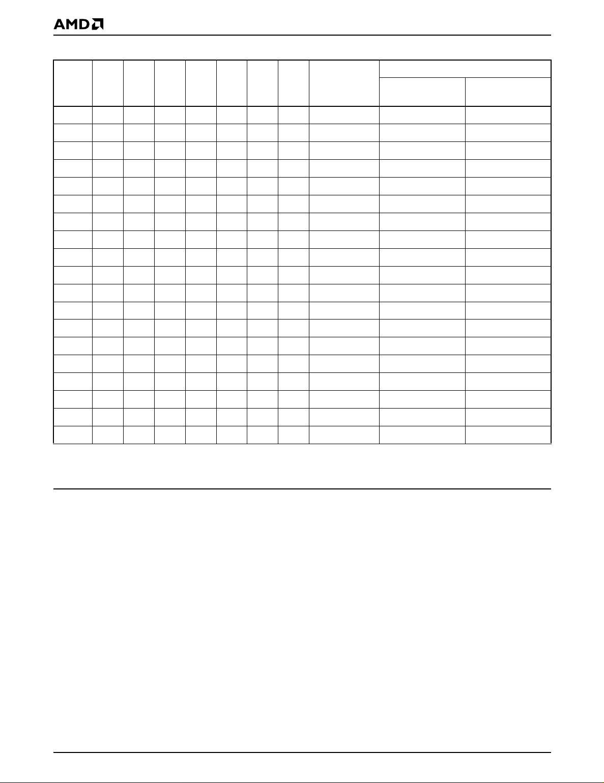
Table 3. Am29F800BB Bottom Boot Block Sector Address Table
Sector Size
(Kbytes/
Sector A18 A17 A16 A15 A14 A13 A12
SA0000000X 16/8 00000h–01FFFh 00000h–03FFFh
SA1 0 0 0 0 0 1 0 8/4 02000h–02FFFh 04000h–05FFFh
SA2 0 0 0 0 0 1 1 8/4 03000h–03FFFh 06000h–07FFFh
SA3 0 0 0 0 1 X X 32/16 04000h–07FFFh 08000h–0FFFFh
SA4 0 0 0 1 X X X 64/32 08000h–0FFFFh 10000h–1FFFFh
SA5 0 0 1 0 X X X 64/32 10000h–17FFFh 20000h–2FFFFh
SA6 0 0 1 1 X X X 64/32 18000h–1FFFFh 30000h–3FFFFh
SA7 0 1 0 0 X X X 64/32 20000h–27FFFh 40000h–4FFFFh
SA8 0 1 0 1 X X X 64/32 28000h–2FFFFh 50000h–5FFFFh
SA9 0 1 1 0 X X X 64/32 30000h–37FFFh 60000h–6FFFFh
SA10 0 1 1 1 X X X 64/32 38000h–3FFFFh 70000h–7FFFFh
SA11 1 0 0 0 X X X 64/32 40000h–47FFFh 80000h–8FFFFh
SA12 1 0 0 1 X X X 64/32 48000h–4FFFFh 90000h–9FFFFh
SA13 1 0 1 0 X X X 64/32 50000h–57FFFh A0000h–AFFFFh
Kwords)
Address Range (in hexadecim al )
(x16)
Address Range
(x8)
Address Range
SA14 1 0 1 1 X X X 64/32 58000h–5FFFFh B0000h–BFFFFh
SA15 1 1 0 0 X X X 64/32 60000h–67FFFh C0000h–CFFFFh
SA16 1 1 0 1 X X X 64/32 68000h–6FFFFh D0000h–DFFFFh
SA17 1 1 1 0 X X X 64/32 70000h–77FFFh E0000h–EFFFFh
SA18 1 1 1 1 X X X 64/32 78000h–7FFFFh F0000h–FFFFFh
Note:
Address range is A18:A-1 in byte mode and A18:A0 in word mode. See the “Word/Byte Configuration” sectionfor more
information.
Autoselect Mode
The autoselect mode provides manufacturer and device identification, and sector protection verification,
through identifier codes output on DQ7–DQ0. This
mode is primarily intended for progr amming equipment
to automatically match a device to be progr ammed with
its correspondi ng programming al gorithm. However,
the autoselect codes can also be accessed in-system
through the command register.
When using programming equipment, the autoselect
mode requires V
(11.5 V to 12.5 V) on address pin
ID
A9. Address pins A6, A1, and A0 must be as shown in
Autoselect Codes (High Voltage Method) table. In addition, when verifying sector protection, the sector ad-
dress must appear on the appropriate highest order
address bits. Refer to the corresponding Sector Address Tables. The Com mand Definitions ta ble shows
the remaining address bits that are don’t c are. When all
necessary bits have been set as required, the programming equipment may then read the corresponding
identifier code on DQ7–DQ0.
To access the autoselect codes in-system, the host
system can issue the autoselect command via the
command register, as shown in the Command Definitions table. This method does not require V
“Command Definitions” for details on using the autoselect mode.
. See
ID
10 Am29F800B
Page 11
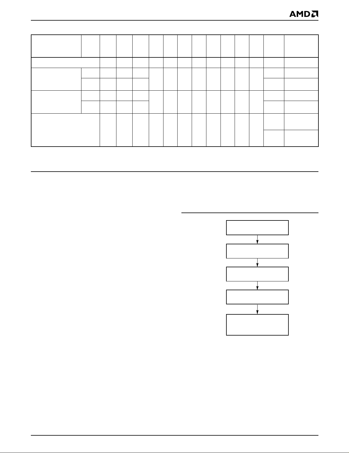
Table 4. Am29F800B Autoselect Codes (High Voltage Method)
Description Mode CE# OE# WE#
A18
to
A12
A11
to
A10 A9
A8
to
A7 A6
A5
to
A2 A1 A0
DQ8
to
DQ15
DQ7
to
DQ0
Manufacturer ID: AMD L L H X X V
Device ID:
Am29F800B
(Top Boot Block)
Device ID:
Am29F800B
(Bottom Boot Block)
Sector Protection Verification L L H SA X V
L = Logic Low = VIL, H = Logic High = VIH, SA = Sector Address, X = Don’t care.
Word L L H
XXVIDXLXLH
Byte L L H X D6h
Word L L H
XXVIDXLXLH
Byte L L H X 58h
Sector Protection/Unprotection
The hardware sector protection feature disables both
program and erase operations in any sector. The
XLXLL X 01h
ID
XLXHL
ID
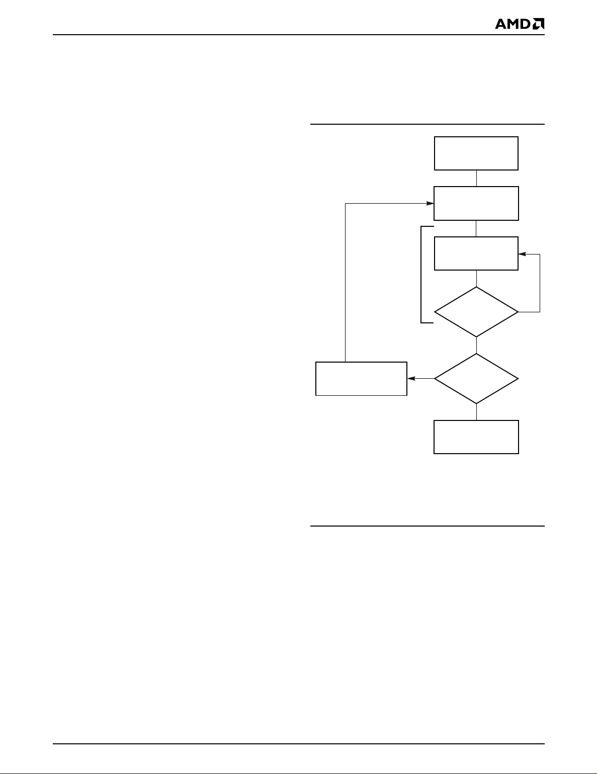
sectors are protected again. Figure 1 shows the algorithm, and the Temporar y Sector Unprotect diagram
shows the tim ing waveforms, for this feature.
hardware sector unprotection feature re-enables both
program and erase operations in previously protected sectors.
Sector protection/unprotection must be implemented
using programming equipment. The procedure requires a high voltage (V
) on address pin A9 and the
ID
control pins. Details on this method are provided in a
supplement, publication number 20374. Contact an
AMD representative to obtain a cop y of the appropriate
document.
22h D6h
22h 58h
X
X
START
RESET# = V
(Note 1)
Perform Erase or
Program Operations
ID
01h
(protected)
00h
(unprotected)
The device is shipped with all s ectors unprotected.
AMD offers the option of programming and protecting
sectors at its factory prior to shipping the device
through AMD’s ExpressFlash™ Servic e. Contact an
AMD representative for details.
It is possible to determine whether a sector is protected
or unprotected. See “Autoselect Mode” for details.
Temporary Sector Unprotect
This feature allows temporary unprotection of previously protected sectors to change data in-system.
The Sector Unprotect mode is acti v ated b y setti ng the
RESET# pin to V
tected sectors can be programmed or erased by selecting the sector addresses. Once V
from the RESET# pin, all the previously protected
. During this mode, formerly pro-
ID
is removed
ID
Am29F800B 11
RESET# = V
Temporary Sector
Unprotect
Completed (Note 2)
Notes:
1. All protected sectors unprotected.
2. All previously protected sectors are protected once
again.
IH
21504D-5
Figure 1. Temporary Sector Unprotect Operation
Page 12

Hardware Data Protection
The command sequence requirement of unlock cycles
for programming or erasing provides data protection
against inadvertent writes (refer to the Command Definitions table). In addition, the following hardware data
protection measures pre vent accidental eras ure or programming, which might otherwise be caused by spurious system level signals during V
power-up and
CC
power-down transitions, or from system noise.
Low V
When V
cept any write cycles. This protects data during V
Write Inhibit
CC
is less than V
CC
, the device does not ac-
LKO
CC
power-up and power-down. The command register and
all internal program/erase circuits are disabled, and the
device resets. Subsequent writes are ignored until V
is greater than V
. The system must provide the
LKO
CC
COMMAND DEFINITIONS
Writing specific addre ss and data commands or sequences into the command register initiates device operations. The Command Definitions table defines the
valid register command sequences. Writing incorrect
address and data values or writing them in the im-
proper sequence resets the device to reading array
data.
All addresses are latched on the falling edge of WE# or
CE#, whichever happens later. All data is latched on
the rising edge of WE# or CE#, whichever happens
first. Refer to the appropriate timing diagrams in the
“AC Characteristics” section.
Reading Array Data
The device is automatically set to reading array data
after device power-up. No commands are required to
retrieve data. The device is also ready to read array
data after comp leting an Embe dded Program or Embedded Erase algorithm.
After the device accepts an Er ase Suspend command,
the device enters the Erase Suspend mode. The system can read array data using the standard read timings, except that if it reads at an address within erasesuspended sectors, the device outputs status data.
After completing a programming operation in the Erase
Suspend mode, the system may once agai n read arra y
data with the same exception. See “Erase Suspend/Erase Resume Commands” for more information
on this mode.
must
The system
able the dev ice f or reading arra y data if DQ5 goes high,
or while in the autoselect mode. See the “Reset Command” section, next.
issue the reset command to re-en-
proper signals to the control pins to prevent unintentional writes when V
is greater than V
CC
LKO
.
Write Pulse “Glitch” Protection
Noise pulses of less than 5 ns (typical) on OE#, CE# or
WE# do not initiate a write cycle.
Logical Inhibit
Write cycles are inhibited by holding any one of OE# =
, CE# = VIH or WE# = VIH. To initiate a write cycle,
V
IL
CE# and WE# must be a logical zero while OE# is a
logical one.
Power-Up Write Inhibit
If WE# = CE# = V
and OE# = VIH during power up , the
IL
device does not accept commands on the rising edge
of WE#. The internal state mac hine is automatically
reset to reading array data on power-up.
See also “Requirements f o r Reading A rr ay Data” in the
“Device Bus Operations” section for more infor mation.
The Read Operations table provides the read parameters, and Read Operation Timings diagram shows the
timing diagram.
Reset Command
Writing the reset command to the devi ce resets the device to reading array data. Address bits are don’t care
for this command.
The reset command may be written between the sequence cycles in an erase command sequence before
erasing begins. This resets the device to reading array
data. Once erasure begins, however, the device ignores reset commands until the operation is complete.
The reset command may be written between the sequence cycles in a program command sequence before programming begins. This resets the device to
reading array data (also applies to programming in
Erase Suspend mode). Once programming begins,
howeve r, the device ignores reset commands until the
operation is complete.
The reset command may be written between the sequence cycles in an autoselect command sequence.
Once in the autoselect mode, t he reset c ommand
be written to return to reading array data (also applies
to autoselect during Erase Suspend).
If DQ5 goes high during a program or erase operation,
writing the reset command returns the device to reading array data (a lso applies during Erase Suspend).
must
12 Am29F800B
Page 13
Autoselect Command Sequence
The autoselect command sequence allows the host
system to access the manufacturer and devices codes,
and determine whether or not a sector is protected.
The Command Definitions table shows the address
and data requirements. This method is an alternative to
that shown in the Autoselect Codes (High Voltage
Method) table, which is intended for PROM programmers and requires V
The autoselect command sequence is initiated by
writing two unlock cycles, followed by the autoselect
command. The device then en ters the autoselect
mode, and the system may read at any address any
number of times, without initiating another command
sequence.
on address bit A9.
ID
from a “0” back to a “1”. Attempting to do so may halt
the operation and set DQ5 to “1”, or cause the Data#
Polling algorithm to indic ate the operation was successful. However, a succeeding read will show that the
data is still “0”. Only erase operations can convert a “0”
to a “1”.
START
Write Program
Command Sequence
A read cycle at address XX00h or retrieves the manufacturer code. A read cycle at address XX01h in word
mode (or 02h in byte mode) returns the device code.
A read cycle containing a sector address (SA) and the
address 02h in word mode (or 04h in byte mode) returns 01h if that sector is protected, or 00h if it is unprotected. Ref e r t o the Se cto r Ad dre ss tables for valid
sector addresses.
The system must write the reset command to exit the
autoselect mode and return to reading array data.
Word/Byte Program Command Sequence
The system may program the device by byte or word,
on depending on the state of the BYTE# pin. Programming is a four-bus-cycle operation. The program command sequence is initiated by writing two unlock write
cycles, followed by the program set-up command. The
program address and data are written next, which in
turn initiate the Embedded Program algorithm. The
not
system is
ings. The device automatically provides internally generated program pulses and verify the programmed cell
margin. The Command Definitions take shows the address and data requirements f or the byte prog ram command sequence.
When the Embedded Program algorithm is complete,
the device then returns to reading array data and addresses are no longer latched. The system can determine the status of the program operation by using DQ7,
DQ6, or RY/BY#. See “Write Operation Status” for information on these status bits.
Any commands written to the device during the Embedded Program Algorithm are ignored. Note that a
hardware reset immediately terminates the programming operation. The program command sequence
should be reinitiated once the de vi ce has reset t o reading array data, to ensure data integrity.
Programming is allowed in any sequence an d across
sector boundaries. A bit cannot be programmed
required to provide further controls or tim-
Data Poll
Embedded
Program
algorithm
in progress
Increment Address
Note: See the appropriate Command Definitions table for
program command sequence.
No
from System
Verify Data?
Yes
Last Address?
Yes
Programming
Completed
No
21504D-5
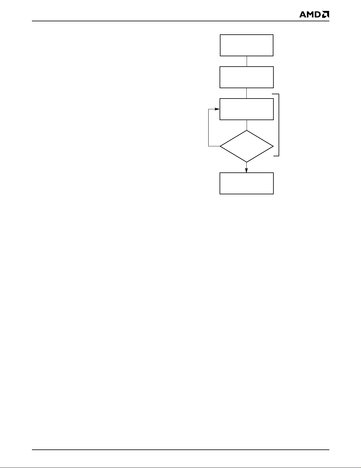
Figure 2. Program Operation
Chip Erase Command Sequence
Chip erase is a six-bu s-cycle oper ation. The chip er ase
command sequence is initiated by writing two unlock
cycles, followed by a set-up command. Two additional
unlock write cycles are then followed by the chip erase
command, which in turn invokes the Embedded Erase
not
algorithm. The device does
preprogram prior to erase. The Embedded Erase algorithm automatically preprograms and verifies the entire
memory for an all zero data patter n prior to electr ical
erase. The system is not required to provide any controls or timings during these operations. The Command
Definitions table shows the address and data requirements for the chip erase command sequence.
require the system to
Am29F800B 13
Page 14

Any commands written to the chip during the Embedded Erase algorithm are ignored. Note that a har dware
reset during the chip erase operation immediately terminates the operation. The Chip Erase command sequence should be reinitiated once the device has
returned to reading array data, t o ensure data int eg rity.
The system can deter mine the status of the erase
operation by using DQ7, DQ6, DQ2, or RY/BY#. See
“Write Operation Status” for inform ation on these
status bits. When the Embedded Erase algorithm is
complete, the device returns to reading array data
and addresses are no longer latc hed.
Figure 3 illustrates the algorithm for the erase operation. See the Erase/Program Operations tables in “AC
Characteristics” for parameters , and to the Chip/Sector
Erase Operation Timings for timing waveforms.
Sector Erase Command Sequence
Sector erase is a six bus cycle operation. The sector
erase command sequence is initiated by writing two unlock cycles, followed by a set-up command. Two additional unlock write cycles are then followed by the
address of the sector to be erased, and the sector
erase command. The Command Definitions table
shows the address and data requirements for the sector erase command sequence.
not
The device does
the memory prior to erase. The Embedded Erase algorithm automatically programs and verifies the sector f or
an all zero data pattern prior to electrical erase. The
system is not required to provide a ny controls or timings during these operations.
After the command sequence is written, a sector erase
time-out of 50 µs begi ns. During the time-out per iod,
additional sector addresses and sector erase commands may be written. Loading the sector erase buffer
may be done in any sequence, and the number of sectors may be from one sector to all secto rs. The time between these additional cycl es must be less than 50 µs,
otherwise the last address and command might not be
accepted, and erasure may begin. It is recommended
that processor interrupts be disab led during this time to
ensure all commands are accepted. The interrupts can
be re-enabled after the last Sector Erase command is
written. If the time between additional sector erase
commands can be assumed to be less than 50 µs, the
system need not monitor DQ3. Any command other
than Sector Erase or Erase Suspend during the
time-out period resets the device to reading array
data. The system must rewrite the command sequence
and any additional sector addresses and commands.
require the system to preprogram
Once the sector erase operation has begun, on ly the
Erase Suspend command is valid. All other commands
are ignored. Note that a hardware reset during the
sector erase operation immediately terminates the operation. The Sector Erase command sequence should
be reinitiated once the device has returned to reading
array data, to ensure data integrity.
When the Embedded Erase algorithm is complete, the
device returns to reading arra y data and addr esses are
no longer latched. The system can determine the status of the erase operation b y using DQ7, DQ6, DQ2, or
RY/BY#. Refer to “Write Operation Status” for information on these status bits.
Figure 3 illustrates the algorithm for the erase operation. Refer to the Erase/Program Operations tables in
the “AC Characteristics” section for parameters, and to
the Sector Erase Operations Timing diagr am for timing
waveforms.
Erase Suspend/Erase Resume Commands
The Erase Suspend command allows t he syste m to interrupt a sector erase ope ration and then read data
from, or program data to, any sector not selected for
erasure. This command is valid only during the sector
erase operation, including the 50 µs time-out period
during the sector erase c ommand sequence. The
Erase Suspend command is ignored if written during
the chip erase operation or Embedded Program algorithm. Writing the Erase Suspend command during the
Sector Erase time-out immediately terminates the
time-out period and suspends the er ase oper at ion. Addresses are “don’t-cares” when writing the Erase Suspend command.
When the Erase Suspend command is written during a
sector erase operation, the de vice requires a maximum
of 20 µs to suspend the erase operation. However,
when the Erase Suspend command is written during
the sector erase time-out, the device immediately terminates the time-out period and suspends the erase
operation.
After the erase operation has been suspended, the
system can read array data from or program data to
any sector not selected for erasu re. (The de vice “er ase
suspends” all sectors selected for erasure.) Normal
read and write timings and command definitions apply.
Reading at any address within erase-suspended sectors produces status data on DQ7–DQ0. The system
can use DQ7, or DQ6 and DQ2 together, to determine
if a sector is actively erasing or is erase-suspended.
See “Write Operation Status” for information on these
status bits.
The system can monitor DQ3 to determine if the sector
erase timer has timed out. (See the “DQ3: Sec tor Erase
Timer” section.) The time-out be gins from the rising
edge of the final WE# pulse in the command sequence .
14 Am29F800B
After an erase-suspended program operation is complete, the system c an once again r ead arra y d ata within
non-suspended sectors. The system can determine
the status of the program operation using the DQ7 or
Page 15
DQ6 status bits, just as in the standard program oper-
ation. See “Write Operation Status” for more infor mation.
The system may also write the autoselect command
sequence when the device is in the Erase Suspend
mode. The device allows reading autoselect codes
even at addresses within erasing sectors, since the
codes are not stored in the memory array. When the
device exits the autoselect mode, the device reverts to
the Erase Suspend mode, and is ready for another
valid operation. See “Autoselect Command Sequence”
for more information.
The system must write the Erase Resume command
(address bits are “don’t care”) to exit the erase suspend
mode and continue the sector erase operat ion. Further
writes of the Resume command are ignored. Another
Erase Suspend command can be written after the device has resumed erasing.
START
Write Erase
Command Sequence
Data Poll
from System
No
Data = FFh?
Erasure Completed
Embedded
Erase
algorithm
in progress
Yes
21504D-6
Notes:
1. See the appropriate Command Definitions table for erase
command sequence.
2. See “DQ3: Sector Erase Timer” for more information.
Figure 3. Erase Operation
Am29F800B 15
Page 16
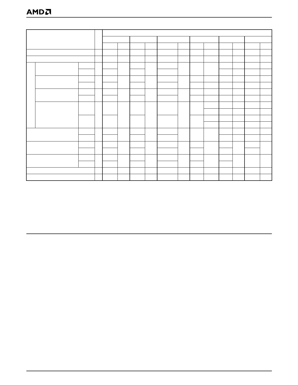
Table 5. Am29F800B Command Definitions
Command
Sequence
(Note 1)
Read (Note 6) 1 RA RD
Reset (Note 7) 1 XXX F0
Manufacturer ID
Device ID,
Top Boot Block
Device ID,
Bottom Boot Block
Autoselect (Note 8)
Sector Protect Verify
(Note 9)
Program
Chip Erase
Sector Erase
Erase Suspend (Note 10) 1 XXX B0
Erase Resume (Note 11) 1 XXX 30
Word
Byte AAA 555 AAA
Word
Byte AAA 555 AAA
Word
Byte AAA 555 AAA
Word
Byte AAA 555 AAA
Word
Byte AAA 555 AAA
Word
Byte AAA 555 AAA AAA 555 AAA
Word
Byte AAA 555 AAA AAA 555
First Second Third Fourth Fifth Sixth
Addr Data Addr Data Addr Data Addr Data Addr Data Addr Data
Cycles
555
4
4
4
4
4
6
6
555
555
555
555
555
555
AA
AA
AA
AA
AA
AA
AA
2AA
2AA
2AA
2AA
2AA
2AA
2AA
55
55
55
55
55
55
55
Bus Cycles (Notes 2–5)
555
555
555
555
555
555
555
90 X00 01
X01 22D6
90
X02
X01 2258
90
X02
XX00
(SA)
X02
90
A0 PA PD
80
80
XX01
(SA)
X04
555
555
D6
58
00
01
AA
AA
2AA
2AA
555
55
55 SA 30
10
Legend:
X = Don’t care
RA = Address of the memory location to be read.
RD = Data read from location RA during read operation.
PA = Address of the memory location to be programmed.
Addresses latch on the falling edge of the WE# or CE# pulse,
whichever happens later.
Notes:
1. See Table 1 for description of bus operations.
2. All values are in hexadecimal.
3. Except when reading array or autoselect data, all bus cycles
are write operations.
4. Data bits DQ15–DQ8 are don’t ca res for unlock and
command cycles.
5. Address bits A18–A11 are don’t cares for unlock and
command cycles, unless SA or PA required.
6. No unlock or command cy cles r equired when reading array data.
7. The Reset command is required to return to reading array
data when device is in the autoselect mode, or if DQ5 goes
high (while the device is providing status da ta).
PD = Data to be programmed at location PA. Data latches on the
rising edge of WE# or CE# pulse, whichever happens first.
SA = Address of the sector to be verified (in autoselect mode) or
erased. Address bits A18–A12 uniquely select any sector.
8. The fourth cycle of the autose lect command sequence is a
read cycle.
9. The data is 00h for an unprotected sector and 01h for a
protected sector. See “Autoselect Command Sequence” See
“Autoselect Command Sequence” for more information.
10. The system may read and program in non-erasing sectors, or
enter the autoselect mode, when in the Erase Suspend
mode. The Erase Suspend command is valid only during a
sector erase operation.
11. The Erase Resume command is valid only during the Erase
Suspend mode.
16 Am29F800B
Page 17
WRITE OPERATION STATUS
The device provides several bits to determine the status of a write operation: DQ2, DQ3, DQ5, DQ6, DQ7,
and RY/BY#. Table 6 and t he f ollowing s ubsections describe the functions of these bits. DQ7, RY/BY#, and
DQ6 each offer a method for determining whether a
program or erase operation is complete or in progress.
These three bits are discussed first.
DQ7: Data# Polling
The Data# Polling bit, DQ7, in dicates to the host
system whether an Embedded Algorithm is in
progress or completed, or whether the device is in
Erase Suspend. Data# P olling is v alid after the rising
edge of the final WE# pulse in the program or erase
command sequence.
During the Em bedded Program algor ithm, the device
outputs on DQ7 the complement of the datum programmed to DQ7. This DQ7 status also applies to programming during Erase Suspend. When the
Embedded Program algorithm is complete, the device
outputs the datum programmed to DQ7. The system
must provide the program address to read valid status
information on DQ7. If a program address falls within a
protected sector, Data# Polling on DQ7 is active for approximately 2 µs, then the device returns to reading
array data.
During the Embedded Erase algorithm, Data# Polling
produces a “0” on DQ7. When the Embedded Erase algorithm is complete, or if the device enters the Erase
Suspend mode, Data# Polling produces a “1” on DQ7.
This is analogous to the complement/true datum output
described for the Embedded Program algorithm: the
erase function changes all the bits in a sector to “1”;
prior to this, the device outputs the “complement,” o r
“0.” The system must provide an address within any of
the sectors selected for erasure to read valid status information on DQ7.
After an erase command sequence is written, if all s ectors selected for erasing are protected, Data# Polling
on DQ7 is active f or appro ximately 100 µs , the n the device returns to reading array data. If not all selected
sectors are protected, the Embedded Erase algorithm
erases the unprotected sectors, and ignores the selected sectors that are protected.
When the system detects DQ7 has changed from the
complement to true data, it can read va lid data at DQ7–
DQ0 on the
following
may change asynchronously with DQ0–DQ6 while
Output Enable (OE#) is asserted low. The Data# Polling Timings (During Embedded Algorithms) figure in
the “AC Characteristics” section illustrates this.
read cycles. This is because DQ7
Table 6 shows the outputs for Data# Polling on DQ7.
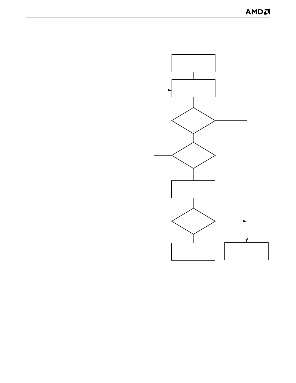
Figure 4 shows the Data# Polling algorithm.
START
Read DQ7–DQ0
Addr = VA
DQ7 = Data?
No
No
Notes:
1. VA = Valid address for programming. During a sector
erase operation, a valid address is an address within any
sector selected for erasure. During chip erase, a valid
address is any non-protected sector address.
2. DQ7 should be rechecked even if DQ5 = “1” because
DQ7 may change simultaneously with DQ5.
DQ5 = 1?
Yes
Read DQ7–DQ0
Addr = VA
DQ7 = Data?
No
FAIL
Yes
Yes
PASS
21504D-7
Figure 4. Data# Polling Algorithm
Am29F800B 17
Page 18

RY/BY#: Ready/Busy#
The RY/BY# is a dedicated, open-drain output pin that
indicates whether an Embedded Algorithm is in
progress or complete. The RY/BY# status is valid after
the rising edge of the final WE# pulse in the command
sequence. Since RY/BY# is an open-drain output, se veral RY/BY# pins can be tied together in parallel with a
pull-up resistor to V
If the output is low (Busy ), the de vice is activ ely er asing
or programming. (T his includes programming in the
Erase Suspend mode.) If th e output is high (Ready) ,
the device is ready to read array data (including during
the Erase Suspend mode), or is in the standby mode.
Table 6 shows the outputs for RY/BY#. The timing diagrams for read, reset, program, and erase shows the
relationship of RY/BY# to other signals.
CC
.
DQ6: Toggle Bit I
Toggle Bit I on DQ6 indicates whethe r an Embedded
Program or Erase algorithm is in progress or complete,
or whether the device has entered the Erase Suspend
mode. Toggle Bit I may be read at any address, and is
valid after the rising edge of the final WE# pulse in the
command sequence (prior to the program or eras e operation), and during the sector erase time-out.
The Write Operation Status table shows the outputs for
Toggle Bit I on DQ6. Refer to Figure 5 for the toggle bit
algorithm, and to the Tog gle Bit Timings figu re in the
“AC Characteristics” section for the timing diagram.
The DQ2 vs. DQ6 figure shows the differences between DQ2 and DQ6 in graphical form. See also the
subsection on “DQ2: Toggle Bit II”.
DQ2: Toggle Bit II
The “Toggle Bit II” on DQ2, when used with DQ6, indicates whether a par ticular sect or is actively erasing
(that is, the Embedded Erase algo rithm is in pro gress),
or whether that sector is erase-suspended. Toggle Bit
II is valid after the rising edge of t he final WE# pulse in
the command sequence.
DQ2 toggles w hen the system reads at addresses
within those sector s that have been selected for erasure. (The system may use either OE# or CE# to control the read cycles.) But DQ2 cannot distinguish
whether the sector is actively erasing or is erase-suspended. DQ6, by comparison, indicates whether the
device is actively erasing, or is in Erase Suspend, but
cannot distinguish which sectors are selected for erasure. Thus, both status bits are required for sector and
mode information. Refer to Table 6 to compar e outputs
for DQ2 and DQ6.
During an Embedded Program or Erase algorithm operation, successive read cycles to any address cause
DQ6 to toggle. (The system may use either OE# or
CE# to control the read cycles.) When the operation is
complete, DQ6 stops toggling.
After an erase command sequence is written, if all
sectors selected for erasing are protected, DQ6 toggles for appro xi mately 100 µ s , t hen returns to read ing
array data. If not all selected sectors are pro tected,
the Embedded Erase algorithm erases the unprotected sectors, and ignores the selected sectors that
are protected.
The system can use DQ6 and DQ2 together to determine whether a sector is actively erasing or is erasesuspended. When the device is activ ely erasing (that is ,
the Embedded Erase algorithm is in progress), DQ6
toggles. When the device enters the Erase Suspend
mode, DQ6 stops toggling. However, the system must
also use DQ2 to determine which sectors are erasing
or erase-suspended. Alternatively, the system can use
DQ7 (see the subsection on “DQ7: Data# Polling”).
If a program address falls within a pro tected sector,
DQ6 toggles for approximately 2 µs after the program
command sequence is written, then returns to reading
array data.
DQ6 also toggles during the erase-suspend-program
mode, and stops toggling once the Embedded Program algorithm is complete.
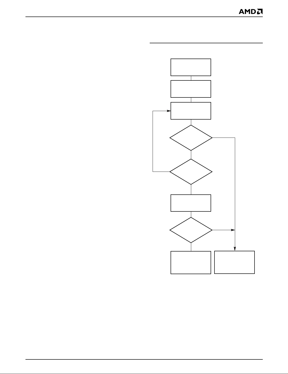
Figure 5 shows the toggle bit algorithm in flowchar t
form, and the section “DQ2: Toggle Bit II” explains the
algorithm. See also the “DQ6: Toggle Bit I” subsection.
Refer to the Toggle Bit Timings figure for the toggle bit
timing diagram. The DQ2 vs. DQ6 figure shows t he differences between DQ2 and DQ6 in graphical f orm.
Reading Toggle Bits DQ6/DQ2
Refer to Figure 5 for the following discussion. Whenever the system initially begins reading toggle bit status, it must read DQ7–DQ0 at least twice in a row to
determine whether a toggle bit is toggling. Typically, a
system would note a nd store th e val ue of the to ggle bit
after the first read. After the second read, the system
would compare the ne w v alue of the toggle bit with the
first. If the toggle bit is not to ggling, the device has
completed the program or erase operation. The system can read arra y data on DQ7–DQ0 on the f ollo wing
read cycle.
However, if after the initial two read cycles, the system
determines that the toggle bit is still toggli ng, the
system also should note whether the value of DQ5 is
high (see the section on DQ5). If it is, the system
should then determine again whether the toggle bit is
toggling, since the toggle bit may have s topped toggling just as DQ5 went high. If the toggle bit is no longer
toggling, the device has successfully comp leted the
program or erase operation. If it is still toggling, the
device did not complete the oper ation successfully, and
18 Am29F800B
Page 19
the system must write the reset command to return to
reading array data.
The remaining scenario is that the system initially determines that the toggle bit is toggling and DQ5 has not
gone high. The system may continue to monitor the
toggle bit and DQ5 through success ive read cycle s, determining the status as described in the previous paragraph. Alterna tively, it may choose to perfor m other
system tasks. In this case, the system must start at the
beginning of the algorithm when it returns to determine
the status of the operation (top of Figure 5).
DQ5: Exceeded Timing Limits
DQ5 indicates whether the program or erase time has
exceeded a specified internal pulse count limit. Under
these conditions DQ5 produces a “1.” This is a failure
condition that indicates the prog ram or er ase cycle was
not successfully completed.
erase command. If DQ3 is high on the second status
check, the last command might not have been accepted. Table 6 shows the outputs for DQ3.
START
Read DQ7–DQ0
Read DQ7–DQ0
(Note 1)
The DQ5 failure condition may appear if the system
tries to program a “1” to a location that i s previously programmed to “0.” Only an era se operation can change
a “0” back to a “1.” Under this condition, the device
halts the operation, and when the operation has ex-
ceeded the timing limits, DQ5 produces a “1.”
Under both these conditions, t he system must issue the
reset command to return the device to reading array
data.
DQ3: Sector Erase Timer
After writing a sector erase command sequence, the
system may read DQ3 to det ermine whether or not an
erase operation has begun. (The sector erase timer
does not apply to the chip erase command.) If additional sectors are selec ted for er asure, th e entire timeout also applies after each add itional sector erase
command. When the time-out is complete, DQ3
switches from “0” to “1.” The system may ignore DQ3
if the system can guar antee t hat the time betw een additional sector erase commands will always be less
than 50 µs. Se e also th e “S ector Er ase Command Sequence” section.
After the sector erase command sequence is written,
the system should read the status on DQ7 (Data# Polling) or DQ6 (Toggle Bit I) to ensure the device has accepted the command sequence, and then read DQ3. If
DQ3 is “1”, the internally controlled erase cycle has begun; all further commands (other than Erase Su spend)
are ignored u ntil the erase operation is complete. If
DQ3 is “0”, the device will accept additional sector
erase commands. To ensure the command has been
accepted, the system software should ch eck the s tatus
of DQ3 prior to and following each subsequent sector
Toggle Bit
= Toggle?
Yes
No
Notes:
1. Read toggle bit twice to determine whether or not it is
toggling. See text.
2. Recheck toggle bit because it may stop toggling as DQ5
changes to “1”. See text.
DQ5 = 1?
Yes
Read DQ7–DQ0
Twice
Toggle Bit
= Toggle?
Yes
Program/Erase
Operation Not
Complete, Write
Reset Command
No
(Notes
1, 2)
No
Program/Erase
Operation Complete
21504D-8
Figure 5. Toggle Bit Algorithm
Am29F800B 19
Page 20
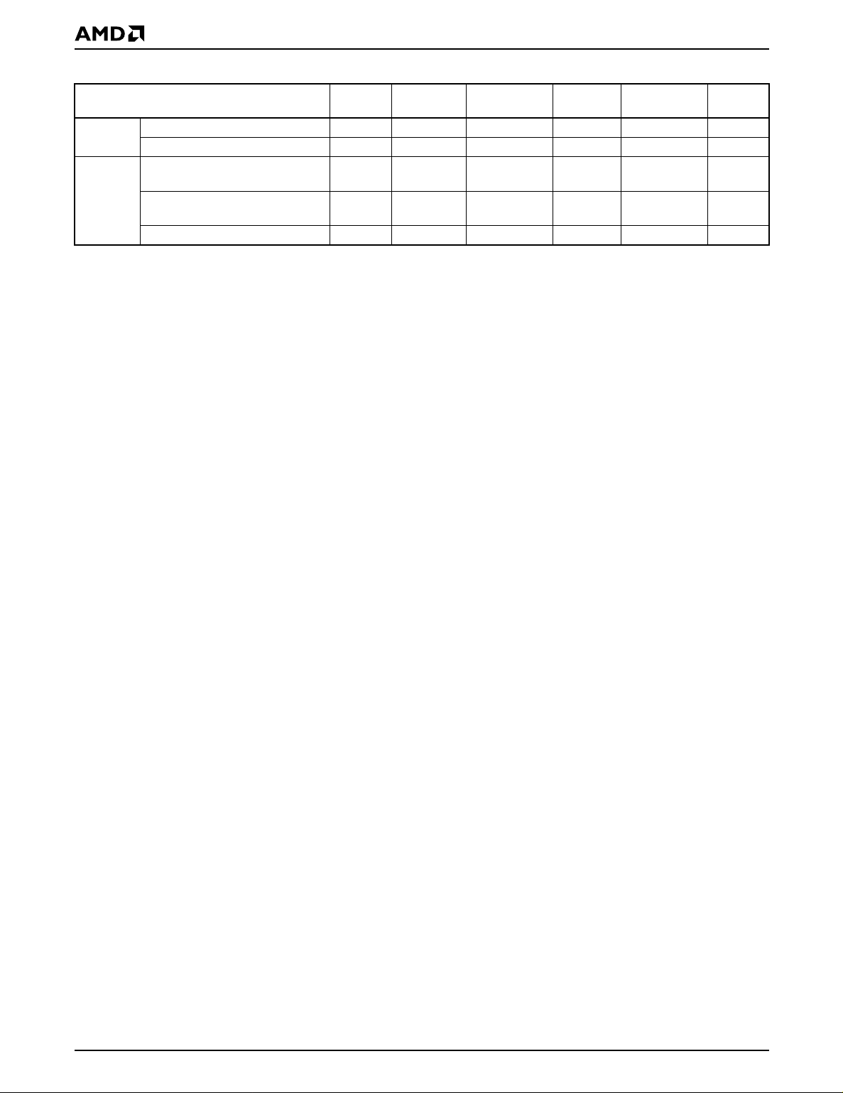
Table 6. Write Operation Status
DQ7
Standard
Mode
Erase
Suspend
Mode
Operation
Embedded Program Algorithm DQ7# Toggle 0 N/A No toggle 0
Embedded Erase Algorithm 0 Toggle 0 1 Toggle 0
Reading within Erase
Suspended Sector
Reading within Non-Erase
Suspended Sector
Erase-Suspend-Program DQ7# Toggle 0 N/A N/A 0
(Note 1) DQ6
1 No toggle 0 N/A Toggle 1
Data Data Data Data Data 1
Notes:
1. DQ7 and DQ2 require a valid address when reading status information. Refer to the appropriate subsection for further details.
2. DQ5 switches to ‘1’ when an Embedded Program or Embedded Erase operation has exceeded the maximum timing limits.
See “DQ5: Exceeded Timing Limits” for more information.
DQ5
(Note 2) DQ3
DQ2
(Note 1) RY/BY#
20 Am29F800B
Page 21
ABSOLUTE MAXIMUM RATINGS
Storage Temperature
Plastic Packages . . . . . . . . . . . . . . . –65°C to +150°C
Ambient Temperature
with Power Applied. . . . . . . . . . . . . . –55°C to +125°C
Voltage with Respect to Ground
(Note 1) . . . . . . . . . . . . . . . .–2.0 V to +7.0 V
V
CC
A9, OE#, and
RESET# (Note 2). . . . . . . . . . . .–2.0 V to +12.5 V
All other pins (Note 1) . . . . . . . . .–0.5 V to +7.0 V
Output Short Circuit Current (Note 3) . . . . . . 200 mA
Notes:
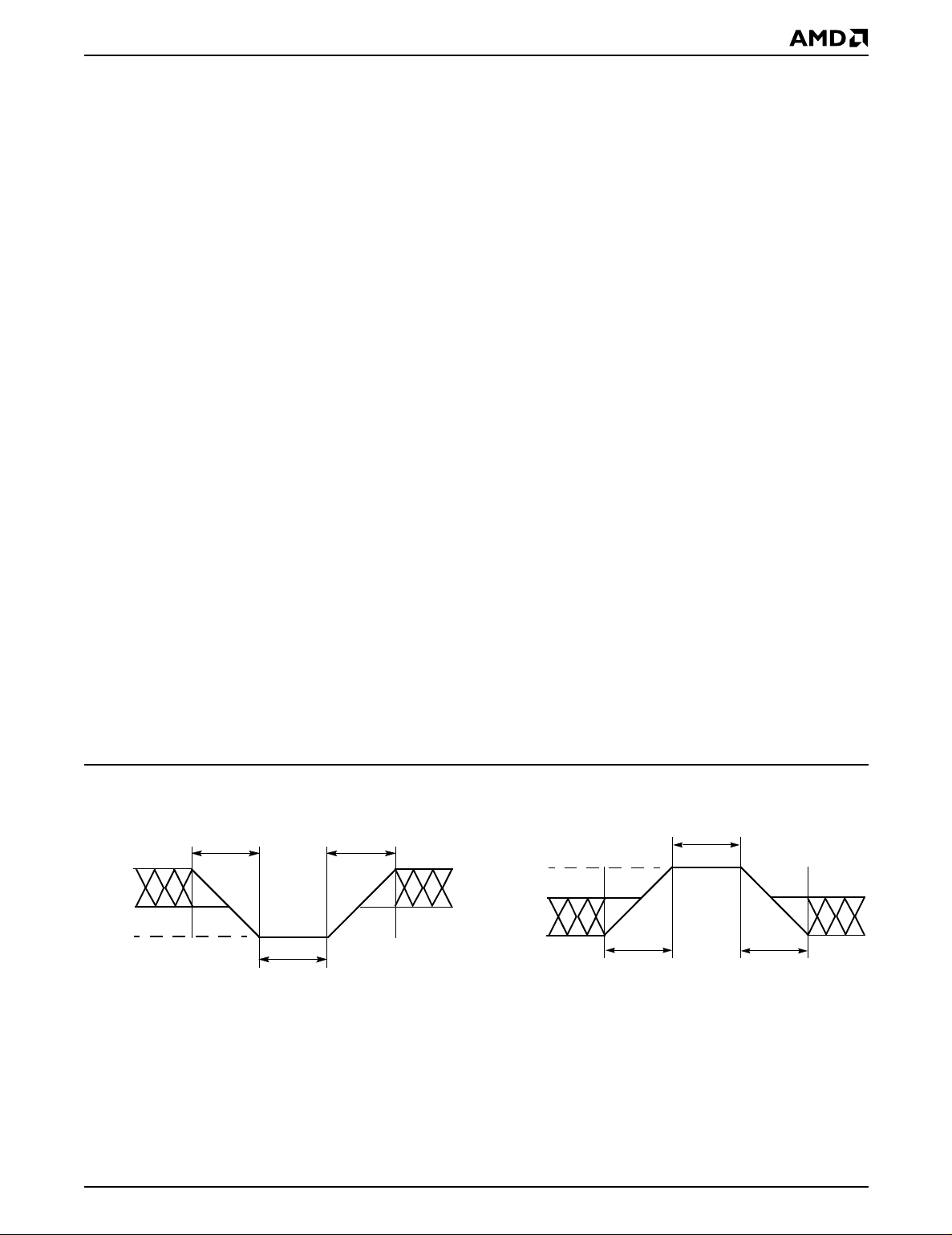
1. Minimum DC voltage on input or I/O pins is –0.5 V. During
voltage transitions, input or I/O pins may undershoot V
to –2.0 V for periods of up to 20 ns. See Figure 6.
Maximum DC voltage on input or I/O pin s is V
During voltage transitions, input or I/O pins may overshoot
to V
+2.0 V for periods up to 20 ns. See Figure 7.
CC
2. Minimum DC input voltage on pins A9, OE#, and RESET#
is –0.5 V. During voltage transitions, A9, OE#, and
RESET# may undershoot V
to 20 ns. See Figure 6. Maximum DC input voltage on pin
A9 is +12.5 V which may overshoot to +13.5 V for periods
up to 20 ns.
3. No more than on e output may be shor te d to ground at a
time. Duration of the short circuit should not be greater
than one second.
Note: Stresses above those listed under “Absolute Maximum
Ratings” may cause permanent damage to the device. This is
a stress rating only; functional operation of the device at
these or any other conditions above those indicated in the
operational sections of this data sheet is not implied.
Exposure of the device to absolute maximum rating
conditions for extended periods may affect device reliability.
to –2.0 V for periods of up
SS
CC
SS
+0.5 V.
OPERATING RANGES
Commercial (C) Devices
Ambient Temperature (T
Industrial (I) Devices
Ambient Temperature (T
Extended (E) Devices
Ambient Temperature (T
VCC Supply Voltages
for all devices. . . . . . . . . . . . . . . +4.5 V to +5.5 V
V
CC
Note: Operating ranges define those limits between which
the functionality of the device is guaranteed.
) . . . . . . . . . . .0°C to +70°C
A
) . . . . . . . . .–40°C to +85°C
A
) . . . . . . . .–55°C to +125°C
A
20 ns
+0.8 V
–0.5 V
–2.0 V
20 ns
20 ns
Figure 6. Maximum Negative Overshoot
Waveform
20 ns
V
CC
+2.0 V
V
CC
+0.5 V
2.0 V
20 ns
21504D-9
20 ns
Figure 7. Maximum Positive Overshoot
Waveform
Am29F800B 21
21504D-10
Page 22
DC CHARACTERISTICS
TTL/NMOS Compatible
Parameter Description Test Conditions Min Typ Max Unit
I
I
I
V
I
I
LIT
I
CC1
CC2
CC3
V
V
V
V
V
LKO
LI
LO
IH
ID
OL
OH
Input Load Current VIN = VSS to VCC, VCC = VCC
A9, OE#, RESET Input Load Current
Output Leakage Current V
VCC Active Read Current
(Notes 1, 2)
VCC Active Write Current
(Notes 2, 3 and 4)
VCC = V
A9 = OE# = RESET# = 12.5 V
= VSS to V
OUT
CE# = V
f
= 5 MHz, Byte Mode
CE# = V
f
= 5 MHz, Word Mode
CE# = V
;
CC max
OE# = VIH,
IL,
OE# = VIH,
IL,
OE# = V
IL,
CC
IH
VCC Standby Current (Notes 2, 5) CE#, OE#, and RESET# = V
IL
Input Low Voltage –0.5 0.8 V
max
IH,
19 40 mA
19 50 mA
36 60 mA
0.4 1 mA
Input High Voltage 2.0
Voltage for A utoselect and Temporary
Sector Unprotect
Output Low Voltage IOL = 5.8 mA, VCC = V
Output High Voltage IOH = –2.5 mA, VCC = V
V
= 5.0 V 11.5 12.5 V
CC
0.45 V
CC min
2.4 V
CC min
±1.0 µA
35 µA
±1.0 µA
V
CC
+ 0.5
V
Low VCC Lock-Out Voltage (Note 4) 3.2 4.2 V
Notes:
1. The I
2. Maximum I
3. I
current listed is typically less than 2 mA/MHz, with OE# at VIH.
CC
specifcations are tested with VCC = VCCmax
CC
active while Embedded Erase or Embedded Program is in progress.
CC
4. Not 100% tested.
5. I
= 20 µA max at extended temperature (>+85°C)
CC3
22 Am29F800B
Page 23
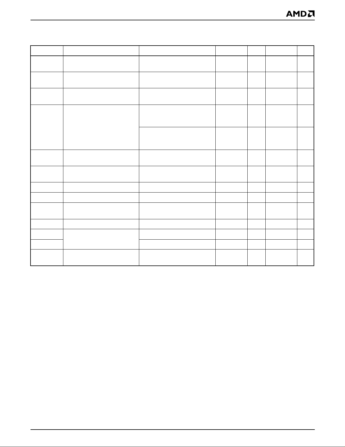
DC CHARACTERISTICS
CMOS Compatible
Parameter Description Test Conditions Min Typ Max Unit
= VSS to VCC,
V
IN
V
= VCC
CC
VCC = V
max
CC max
,
A9 = OE# = RESET = 12.5 V
V
= VSS to VCC,
OUT
V
= V
CC
CC max
CE# = V
f
= 5 MHz
OE# = VIH,
IL,
Byte Mode
CE# = VIL, OE# = VIH,
f
= 5 MHz
Word Mode
±1.0 µA
35 µA
±1.0 µA
20 40 mA
28 50 mA
I
I
I
CC1
I
LI
LIT
LO
Input Load Current
A9, OE#, RESET Input Load
Current
Output Leakage Current
VCC Active Read Current
(Note 2)
V
V
V
I
CC2
I
CC3
V
V
V
V
OH1
OH2
LKO
OL
VCC Active Write Current
(Notes 1, 2, 3)
VCC Standby Current (Note 2)
IL
IH
ID
Input Low Voltage –0.5 0.8 V
Input High Voltage 0.7 x V
Voltage for Autoselect and
Temporary Sector Unprotect
Output Low Voltage IOL = 5.8 mA, VCC = V
Output High Voltage
Low VCC Lock-Out Voltage
(Note 3)
CE# = V
IL,
CE# and RESET# = V
OE# = V
IH
VCC = 5.0 V 11.5 12.5 V
I
= –2.5 mA, VCC = V
OH
IOH = –100 µA, VCC = V
Notes:
1. I
active while Embedded Erase or Embedded Program is in progress.
CC
2. Maximum I
specifcations are tested with VCC = VCCmax
CC
3. Not 100% tested.
OE# = V
IH
30 50 mA
±0.5 V,
CC
0.45 V
CC min
0.85 V
CC min
VCC–0.4 V
CC min
0.3 5 µA
CC
CC
VCC + 0.3 V
3.2 4.2 V
V
Am29F800B 23
Page 24
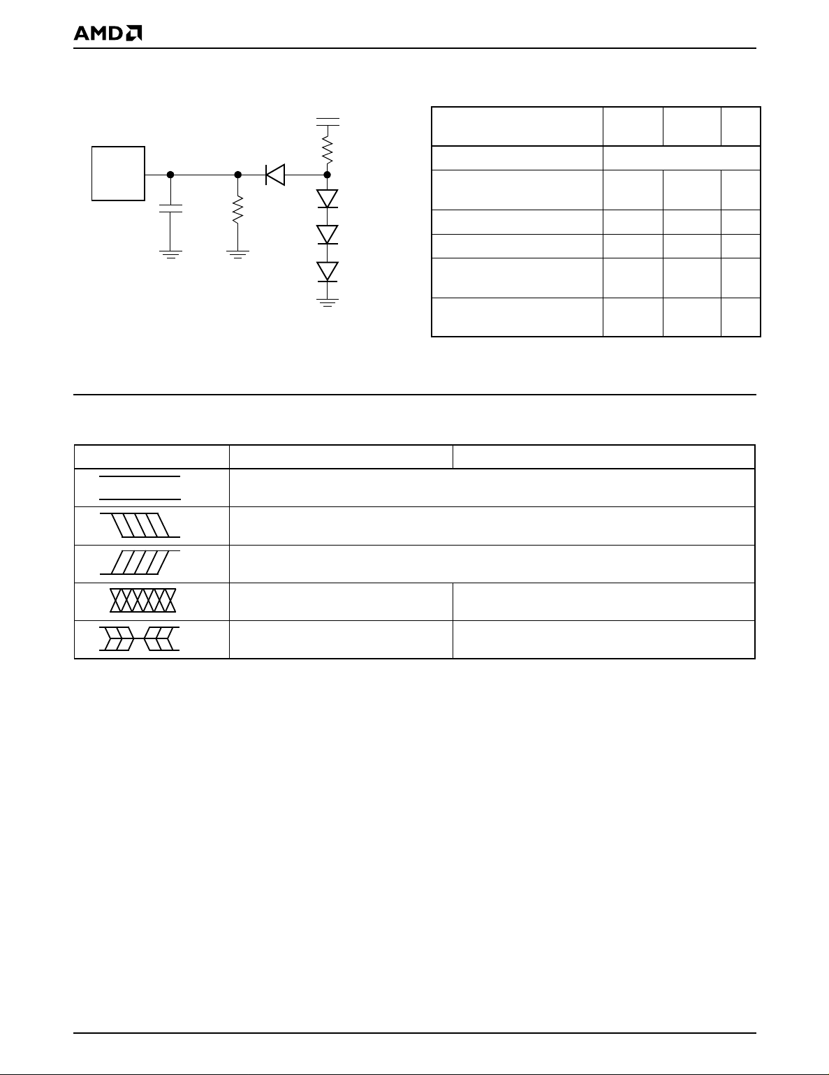
TEST CONDITIONS
Device
Under
Test
C
L
6.2 kΩ
5.0 V
2.7 kΩ
Table 7. Test Specifications
All
Test Condition -55
Output Load 1 TTL gate
Output Load Capacitance, C
(including jig capacitance)
Input Rise and Fall Times 5 20 ns
Input Pulse Levels 0.0–3.0 0.45–2.4 V
L
30 100 pF
others Unit
Note:
Diodes are IN3064 or equivalents.
Figure 8. Test Setup
KEY TO SWITCHING WAVEFORMS
WAVEFORM INPUTS OUTPUTS
Don’t Care, Any Change Permitted Changing, State Unknown
Does Not Apply Center Line is High Impedance State (High Z)
21504D-11
Input timing measurement
reference levels
Output timing measurement
reference levels
Steady
Changing from H to L
Changing from L to H
1.5 0.8, 2.0 V
1.5 0.8, 2.0 V
24 Am29F800B
KS000010-PAL
Page 25
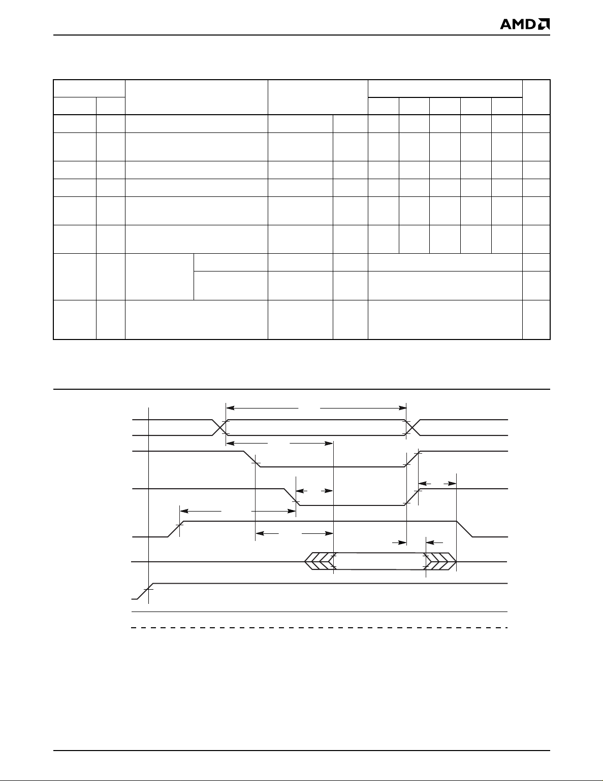
AC CHARACTERISTICS
Read Operations
Parameter
JEDEC Std Test Setup -55 -70 -90 -120 -150 Unit
t
AVAV
t
AVQVtACC
t
ELQV
t
GLQV
t
EHQZ
t
GHQZ
Description
t
Read Cycle Time (Note 1) Min 55 70 90 120 150 ns
RC
Address to Output Delay
t
Chip Enable to Output Delay OE# = V
CE
t
Output Enable to Output Delay Max 30 30 35 50 55 ns
OE
Chip Enable to Output High Z (Note
t
DF
1)
Output Enable to Output High Z
t
DF
(Note 1)
Read Min 0 ns
Toggle and
Data# Polling
t
OEH
Output Enable
Hold Time
(Note 1)
CE# = V
OE# = V
IL
Max 55 70 90 120 150 ns
IL
Max 55 70 90 120 150 ns
IL
Max 20 20 20 30 35 ns
Max 20 20 20 30 35 n s
Min 10 ns
Speed Options
Output Hold Time From Addresses,
t
AXQX
CE# or OE#, Whichever Occurs
t
OH
Min 0 ns
First (Note 1)
Notes:
1. Not 100% tested.
2. See Figure 8 and Table 7 for test specifications.
Addresses
CE#
OE#
WE#
Outputs
RESET#
RY/BY#
0 V
t
RC
Addresses Stable
t
ACC
t
OE
t
OEH
t
CE
HIGH Z
Output Valid
Figure 9. Read Operations Timings
t
DF
t
OH
HIGH Z
21504D-12
Am29F800B 25
Page 26
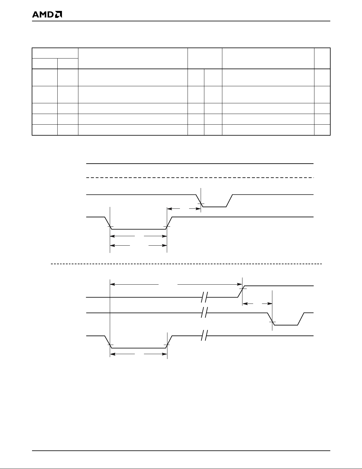
AC CHARACTERISTICS
Hardware Reset (RESET#)
Parameter
Description All Speed OptionsJEDEC Std Test Setup Unit
t
READY
t
READY
t
RP
t
RH
t
RB
Note:
Not 100% tested.
RY/BY#
CE#, OE#
RESET#
RESET# Pin Low (During Embedded
Algorithms) to Read or Write (See Note)
RESET# Pin Low (NOT During Embedded
Algorithms) to Read or Write (See Note)
Max 20 µs
Max 500 ns
RESET# Pulse Width Min 500 ns
RESET# High Time Before Read (See Note) Min 50 ns
RY/BY# Recovery Time Min 0 ns
t
RH
t
RP
t
Ready
RY/BY#
CE#, OE#
RESET#
Reset Timings NOT during Embedded Algorithms
Reset Timings during Embedded Algorithms
t
Ready
t
RP
Figure 10. RESET# Timings
t
RB
21504D-13
26 Am29F800B
Page 27
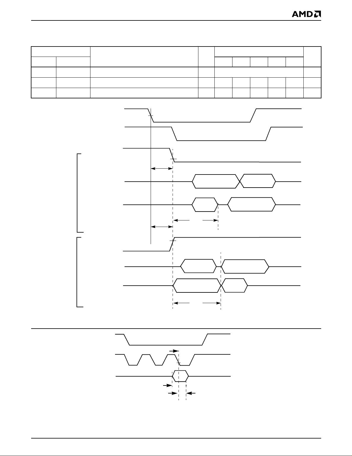
AC CHARACTERISTICS
Word/Byte Configuration (BYTE#)
Parameter Speed Options
JEDEC Std Description -55 -70 -90 -120 -150 Unit
t
ELFL/tELFH
t
FLQZ
t
FHQV
BYTE#
Switching
from word
to byte
mode
CE# to BYTE# Switching Low or High Max 5 ns
BYTE# Switching Low to Output HIGH Z Max 20 20 20 30 35 ns
BYTE# Switching High to Output Active Min 55 70 90 120 150 ns
CE#
OE#
BYTE#
t
DQ0–DQ14
DQ15/A-1
ELFL
t
ELFH
Data Output
(DQ0–DQ14)
DQ15
Output
t
FLQZ
Data Output
(DQ0–DQ7)
Address
Input
BYTE#
BYTE#
Switching
from byte
to word
DQ0–DQ14
Data Output
(DQ0–DQ7)
mode
DQ15/A-1
Address
Input
t
FHQV
Figure 11. BYTE# Timings for Read Operations
CE#
The falling edge of the last WE# signal
WE#
BYTE#
t
SET
(tAS)
t
HOLD
(tAH)
Note: Refer to the Erase/Program Operations table for tAS and tAH specifications.
Figure 12. BYTE# Timings for Write Operations
Data Output
(DQ0–DQ14)
DQ15
Output
21504D-14
21504D-15
Am29F800B 27
Page 28
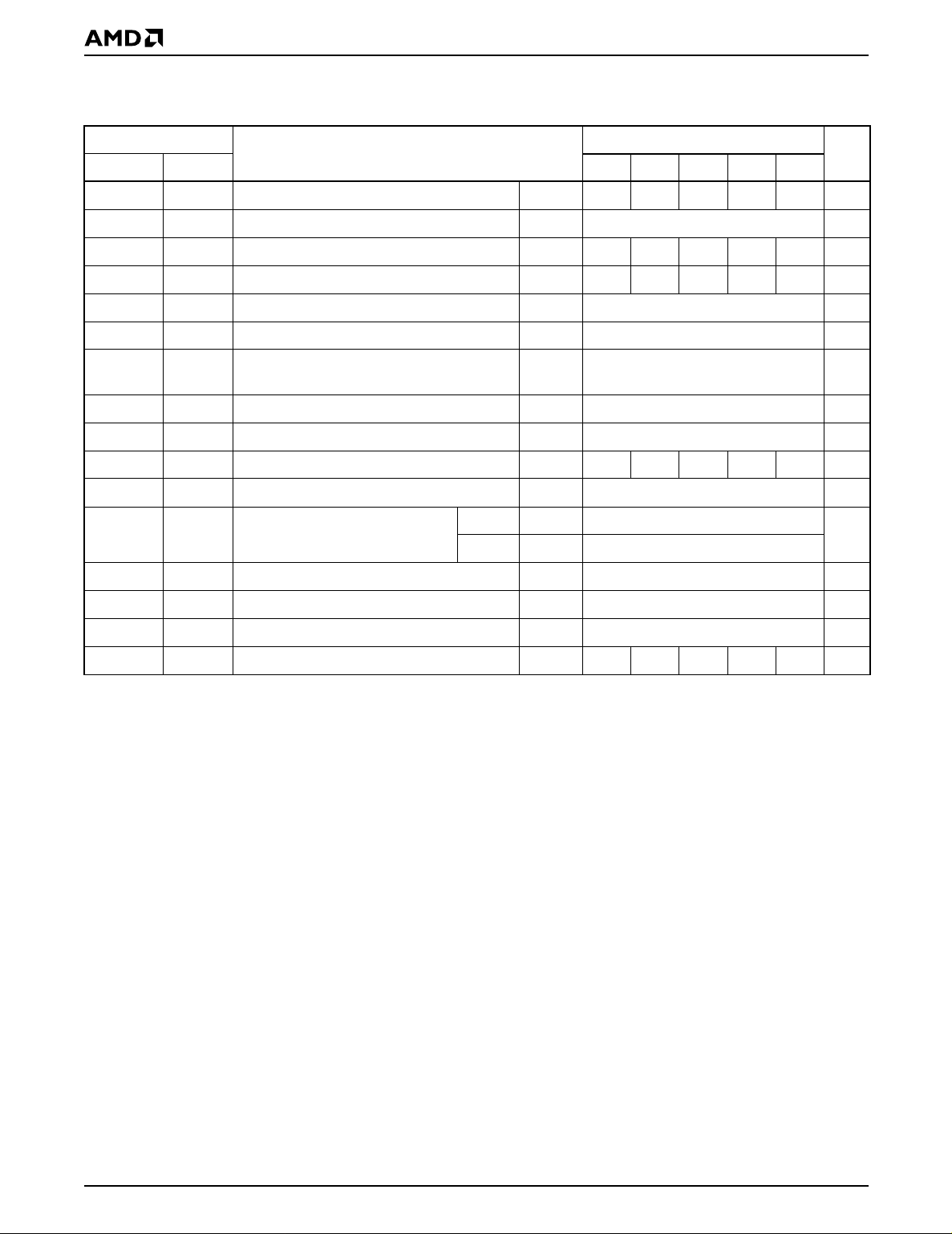
AC CHARACTERISTICS
Erase/Program Operations
Parameter
WC
t
AS
t
AH
t
DS
t
DH
OES
t
CS
t
CH
WP
Description
Write Cycle Time (Note 1) Min 55 70 90 120 150 ns
Address Setup Time Min 0 ns
Address Hold Time Min 45 45 45 50 50 ns
Data Setup Time Min 25 30 45 50 50 ns
Data Hold Time Min 0 ns
Output Enable Setup Time Min 0 ns
Read Recovery Time Before Write
(OE# High to WE# Low)
Min 0 ns
CE# Setup Time Min 0 ns
CE# Hold Time Min 0 ns
Write Pulse Width Min 30 35 45 50 50 ns
Write Pulse Width High Min 20 ns
JEDEC Std -55 -70 -90 -120 -150 Unit
t
AVAV
t
AVWL
t
WLAX
t
DVWH
t
WHDX
t
t
t
GHWL
t
ELWL
t
WHEH
t
WLWH
t
WHWL
t
GHWL
t
t
WPH
Speed Options
Byte Typ 7
t
WHWH1tWHWH1
t
WHWH2tWHWH2
t
VCS
t
RB
t
BUSY
Programming Operation (Note 2)
Word Typ 12
Sector Erase Operation (Note 2) Typ 1 sec
VCC Setup Time (Note 1) Min 50 µs
Recovery Time from RY/BY# Min 0 ns
Program/Erase Valid to RY/BY# Delay Min 30 30 35 50 55 ns
µs
Notes:
1. Not 100% tested.
2. See the “Erase and Programming Performance” section for more information.
28 Am29F800B
Page 29
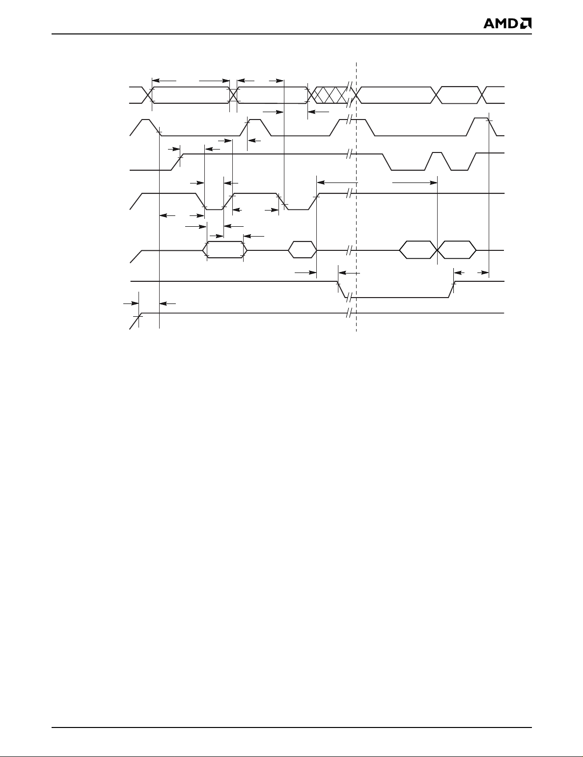
AC CHARACTERISTICS
Program Command Sequence (last two cycles)
t
WC
Addresses
555h
CE#
t
GHWL
OE#
t
WP
WE#
t
CS
t
DS
t
DH
Data
A0h
RY/BY#
t
VCS
V
CC
Notes:
1. PA = program address, PD = program data, D
2. Illustration shows device in word mode.
Read Status Data (last two cycles)
t
AS
PA PA
t
AH
t
CH
t
t
WPH
PA
WHWH1
PD
t
BUSY
is the true data at the program address.
OUT
Status
D
OUT
t
RB
21504D-16
Figure 13. Program Operation Timings
Am29F800B 29
Page 30
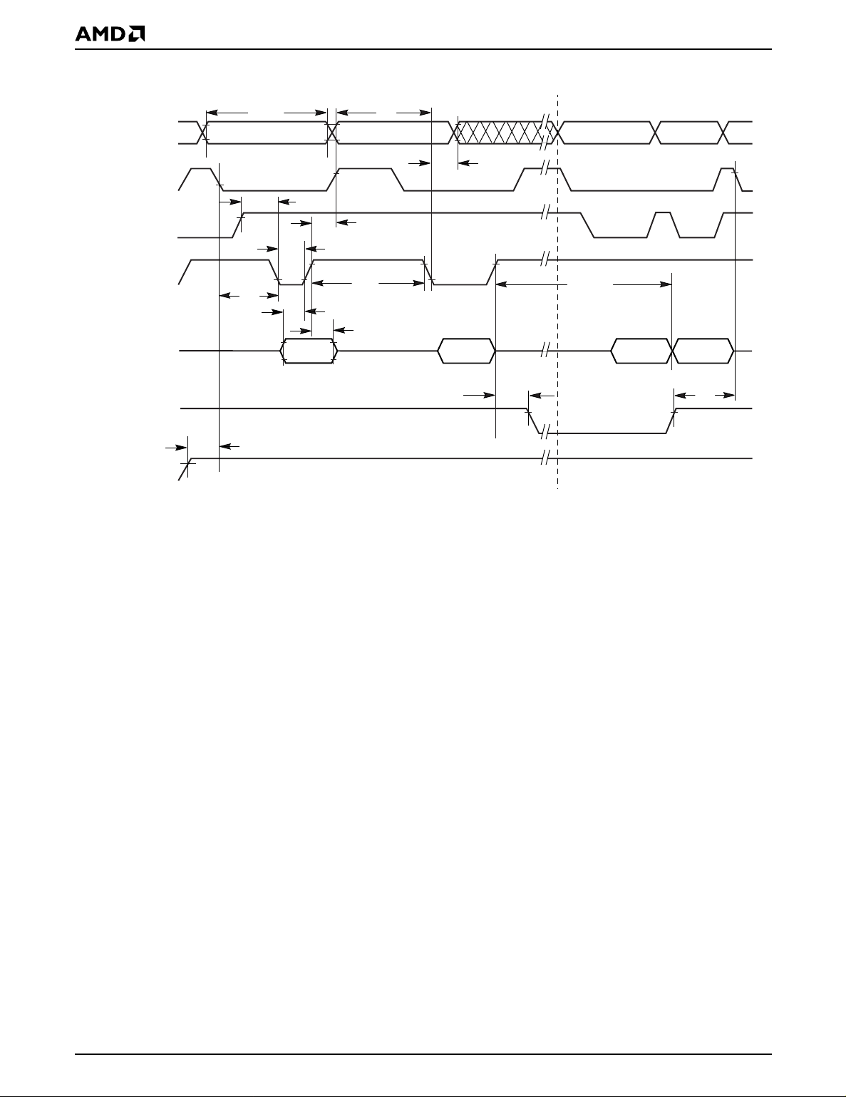
AC CHARACTERISTICS
t
AS
555h for chip erase
t
AH
Addresses
t
WC
2AAh SA
CE#
t
GHWL
t
t
WP
t
DS
55h
CH
t
WPH
t
DH
30h
10 for Chip Erase
OE#
WE#
Data
t
CS
RY/BY#
t
VCS
V
CC
Note: SA = Sector Address. VA = Valid Address for reading status data.
Figure 14. Chip/Sector Erase Operation Timings
t
BUSY
t
WHWH2
VA
In
Progress
VA
Complete
t
RB
21504-17
30 Am29F800B
Page 31
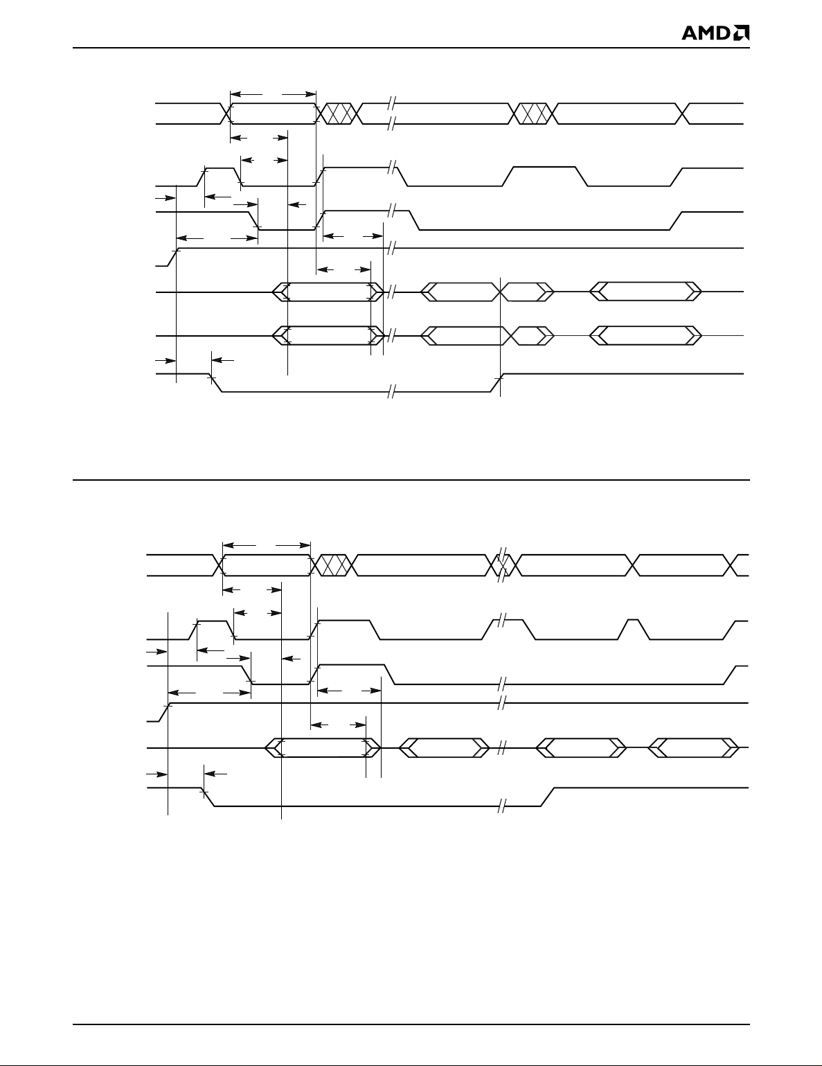
AC CHARACTERISTICS
Addresses
CE#
t
CH
OE#
t
WE#
DQ7
OEH
t
ACC
t
CE
t
VA
t
RC
OE
t
t
OH
Complement
DF
VA VA
Complement
True
Valid Data
High Z
DQ0–DQ6
t
BUSY
Status Data
Status Data
True
Valid Data
High Z
RY/BY#
Note:
V A = Valid address. Illustration shows first status cycle after command sequence, last status read cycle, and array data read cycle.
21504D-18
Figure 15. Data# Polling Timings (During Embedded Algorithms)
t
RC
Addresses
CE#
OE#
WE#
DQ6/DQ2
RY/BY#
t
CH
t
BUSY
t
OEH
High Z
t
ACC
VA
t
CE
t
OE
t
DF
t
OH
(first read) (second read) (stops toggling)
VA VA
Valid Status
VA
Valid DataValid StatusValid Status
Note:
V A = Valid address; not required for DQ6. Illustration shows first two status cycle after command sequence, last status read cycle,
and array data read cycle.
21504D-19
Figure 16. Toggle Bit Timings (During Embedded Algorithms)
Am29F800B 31
Page 32
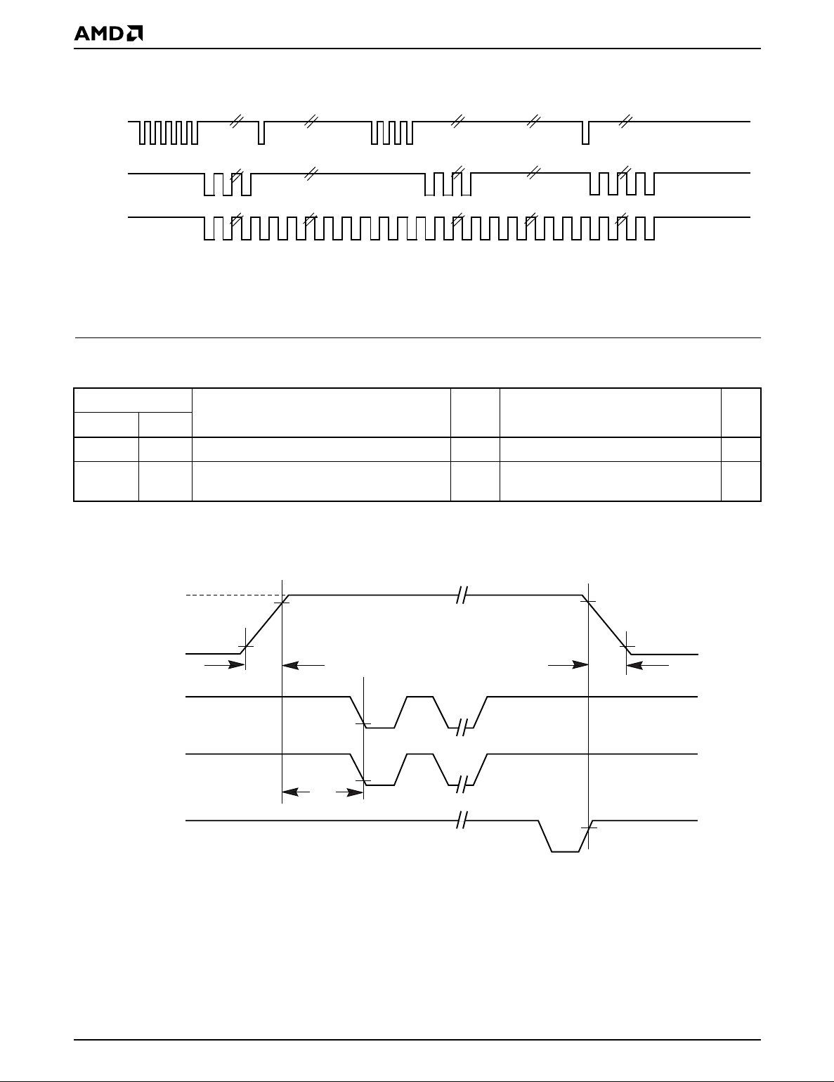
AC CHARACTERISTICS
Enter
Embedded
Erasing
WE#
DQ6
DQ2
Note: The system may use OE# or CE# to toggle DQ2 and DQ6. DQ2 toggles only when read at an address within the
erase-suspended sector.
Erase
Erase
Suspend
Erase Suspend
Enter Erase
Suspend Program
Read
Figure 17. DQ2 vs. DQ6
Erase
Suspend
Program
Erase Suspend
Read
Erase
Resume
Erase
Erase
Complete
21504D-20
Temporary Sector Unprotect
Parameter
All Speed OptionsJEDEC Std Description Unit
t
VIDR VID
t
RSP
Note: Not 100 % test ed.
12 V
RESET#
0 or 5 V
CE#
WE#
RY/BY#
Rise and Fall Time (See Note) Min 500 ns
RESET# Setup Time for Temporary Sector
Unprotect
Min 4 µs
0 or 5 V
t
VIDR
t
VIDR
Program or Erase Command Sequence
t
RSP
Figure 18. Temporary Sector Unprotect Timing Diagram
32 Am29F800B
21504D-21
Page 33
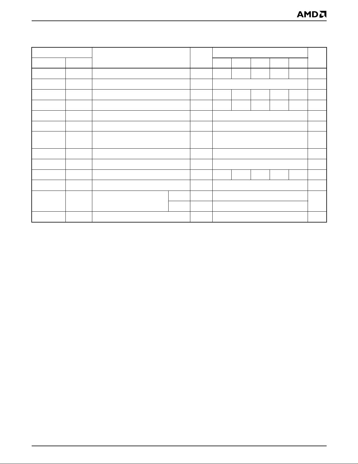
AC CHARACTERISTICS
Alternate CE# Controlled Erase/Program Operations
Parameter Speed Options
JEDEC Std Description -55 -70 -90 -120 -150 Unit
t
AVAV
t
AVEL
t
ELAX
t
DVEH
t
EHDX
t
GHEL
t
WLEL
t
EHWH
t
ELEH
t
EHEL
t
WHWH1
t
WHWH2
t
t
t
t
t
t
OES
t
GHEL
t
t
t
t
CPH
t
WHWH1
t
WHWH2
Write Cycle Time (Note 1) Min 55 70 90 120 150 ns
WC
Address Setup Time Min 0 ns
AS
Address Hold Time Min 45 45 45 50 50 ns
AH
Data Setup Time Min 25 30 45 50 50 ns
DS
Data Hold Time Min 0 ns
DH
Output Enable Setup Time Min 0 ns
Read Recovery Time Before Write
(OE# High to WE# Low)
WE# Setup Time Min 0 ns
WS
WE# Hold Time Min 0 ns
WH
CE# Pulse Width Min 30 35 45 50 50 ns
CP
Min 0 ns
CE# Pulse Width High Min 20 ns
Programming Operation
(Note 2)
Byte Typ 7
Word T yp 12
Sector Erase Operation (Note 2) Typ 1 sec
Notes:
1. Not 100% tested.
2. See the “Erase and Programming Performance” section for more information.
µs
Am29F800B 33
Page 34
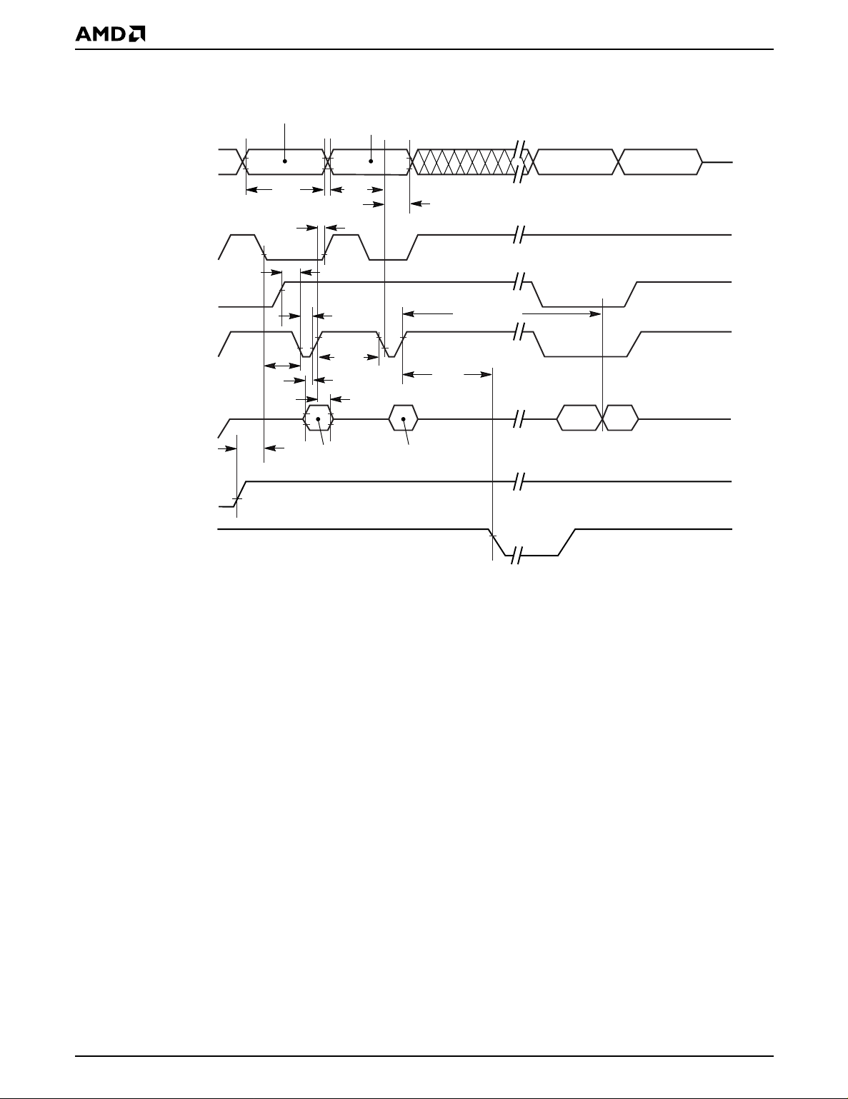
AC CHARACTERISTICS
Addresses
WE#
OE#
CE#
Data
RESET#
555 for program
2AA for erase
t
WC
t
WH
t
WS
t
RH
PA for program
SA for sector erase
555 for chip erase
t
AS
t
GHEL
t
CP
t
CPH
t
DS
t
DH
A0 for program
55 for erase
t
AH
t
PD for program
30 for sector erase
10 for chip erase
t
BUSY
Data# Polling
WHWH1 or 2
PA
DQ7# D
OUT
RY/BY#
Notes:
1. PA = Program Address, PD = Program Data, SA = Sector Address, DQ7# = Complement of Data Input, D
2. Figure indicates the last two bus cycles of the command sequence, with the device in word mode.
Figure 19. Alternate CE# Controlled Write Operation Timings
= Array Data.
OUT
21504D-22
34 Am29F800B
Page 35
ERASE AND PROGRAMMING PERFORMANCE
Parameter Typ (Note 1) Max (Note 3) Unit Comments
Sector Erase Time 1.0 8 s
Chip Erase Time (Note 2) 19 s
Byte Programming Time 7 300 µs
Word Programming Time 12 500 µs
Chip Programming Time
(Note 2)
Byte Mode 7.2 21.6 s
Word Mode 6.3 18.6 s
Excludes 00h programming
prior to erasure (Note 4)
Excludes system level
overhead (Note 5)
Notes:
1. Typical program and erase times assume the following conditions: 25
°
C, 5.0 V VCC, 1,000,000 cycles. Additionally,
programming typicals assume checkerboard pattern.
2. Under worst case conditions of 90°C, V
= 4.5 V, 1,000,000 cycles.
CC
3. The typical chip programming time is considerably less than the maximum chip programming time listed, since most bytes
program faster than the maximum program times listed.
4. In the pre-programming step of the Embedded Erase algorithm, all bytes are programmed to 00h before erasure.
5. System-level overhead is the time required to execute the four-bus-cycle sequence for the program command. See Table 5
for further information on command definitions.
6. The device has a guaranteed minimum erase and program cycle endurance of 1,000,000 cycles.
LATCHUP CHARACTERISTICS
Description Min Max
Input voltage with respect to V
(including A9, OE#, and RESE T#)
on all pins except I/O pins
SS
–1.0 V 12.5 V
Input voltage with respect to V
Current –100 mA +100 mA
V
CC
on all I/O pins –1.0 V VCC + 1.0 V
SS
Includes all pins except VCC. Test conditions: VCC = 5.0 V, one pin at a time.
TSOP AND SO PIN CAPACITANCE
Parameter
Symbol Parameter Description Test Setup Typ Max Unit
Input Capacitance VIN = 0 6 7.5 pF
Output Capacitance V
Control Pin Capacitance VIN = 0 7.5 9 pF
= 0 8.5 12 pF
OUT
C
C
C
IN
OUT
IN2
Notes:
1. Sampled, not 100% tested.
2. Test conditions T
= 25°C, f = 1.0 MHz.
A
DATA RETENTION
Parameter Test Conditions Min Unit
Minimum Pattern Data Retention Time
150°C 10 Years
125°C 20 Years
Am29F800B 35
Page 36
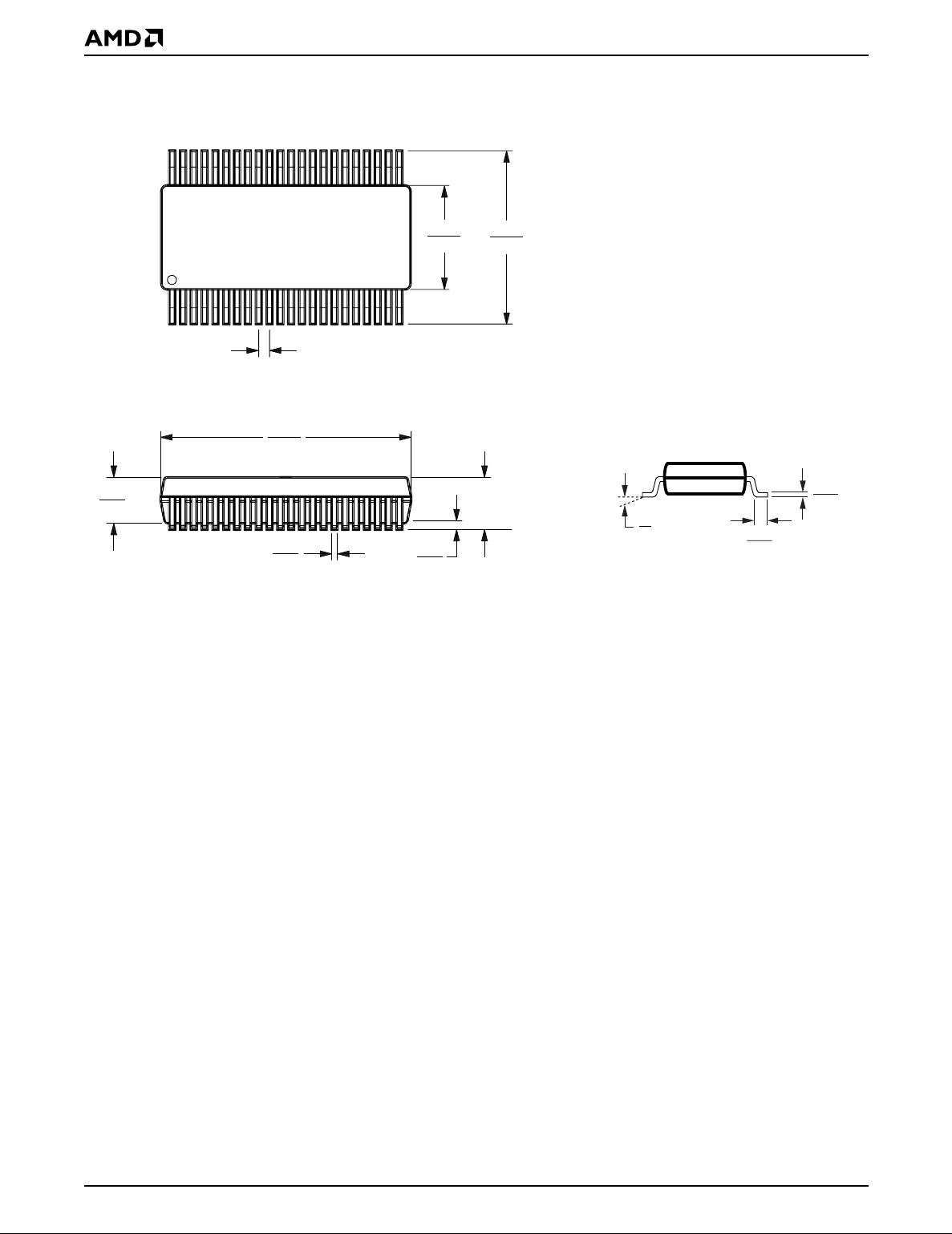
PHYSICAL DIMENSIONS
SO 044—44-Pin Small Outline Package (measured in millimeters)
2.17
2.45
44
23
13.10
13.50
1
1.27 NOM.
TOP VIEW
28.00
28.40
0.35
0.50
SIDE VIEW
22
0.10
0.35
2.80
MAX.
15.70
16.30
SEATING
PLANE
0°
8°
0.10
0.21
0.60
1.00
END VIEW
16-038-SO44-2
SO 044
DF83
8-8-96 lv
36 Am29F800B
Page 37
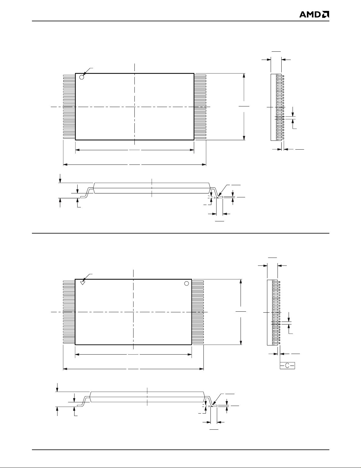
PHYSICAL DIMENSIONS (continued)
TS 048—48-Pin Standard Thin Small Outline Package (measured in millimeters)
0.95
1.05
Pin 1 I.D.
1
24
18.30
18.50
19.80
20.20
48
11.90
12.10
25
0.50 BSC
0.05
0.15
16-038-TS48-2
TS 048
DT95
8-8-96 lv
1.20
MAX
0.25MM (0.0098") BSC
0.08
0.20
0.10
0°
0.21
5°
0.50
0.70
TSR048—48-Pin Reverse Thin Small Outline Package (measured in millimeters)
0.95
1.05
Pin 1 I.D.
1
24
18.30
18.50
19.80
20.20
48
11.90
12.10
25
0.05
0.15
SEATING PLANE
0.50 BSC
1.20
MAX
0.25MM (0.0098") BSC
16-038-TS48
0.08
0.20
0.10
0°
5°
0.50
0.70
0.21
TSR048
DT95
8-8-96 lv
Am29F800B 37
Page 38

REVISION SUMMARY
Revision B (October 1997)
Global
Added -55 speed option. Changed data sheet designation from Advance Information to Preliminary.
Sector Protection/Unprotection
Corrected text to indicate that these functions can only
be implemented using programming equipment.
Table 1, Device Bus Operations
Revised to indicate inputs for both CE# and RESET#
are required for standby mode.
Program Command Sequence
Changed to indicate D ata# Polling is active for 2 µs
after a program command sequence if the sector specified is protected.
Sector Erase Command Sequence and DQ3: Sector Erase Timer
Corrected sector erase timeout to 50 µs.
Erase Suspend Command
Changed to indicate that the device suspends the
erase operation a maximum of 20 µs after the rising
edge of WE#.
DC Characteristics
Changed to indicate V
to 12.5 V, with a V
min and max values are 11.5
ID
test condition of 5.0 V. Added
CC
typical values to TTL table. Revised CMOS ty pical
standby current (I
CC3
).
Figure 14: Chip/Sector Erase Operation Timings;
Figure 19: Alternate CE# Controlled Write
Operation TImings
Corrected hexadecimal values in address and data
wavef orms. In Figure 19, corrected dat a v alues f or chip
and sector erase.
Erase and Programming Performance
Corrected word and chip programming times.
Revision C (January 1998)
Global
Formatted for consistency with other 5.0 volt-only
data sheets.
Revision C+1 (April 1998)
Distinctive Characteristics
Changed typical program/erase current to 30 mA to
match the CMOS DC Characteristics table.
Changed minimum endurance to 1 million write cycles
per sector guaranteed.
AC Characteristics
Erase/Program Operations:
ence for t
WHWH1
and t
100% tested. Changed t
ns device. Changed t
Corrected the notes refer-
WHWH2
WHWH1
. These parameters are
and tCP specifications for 55
DS
word mode specification
to 12 µs.
Alternate CE# C ontrolled Erase/Program Operations:
Corrected the notes ref erence f or t
WHWH1
These parameters are 100% tested. Changed t
specifications for 55 ns device. Changed t
t
CP
and t
WHWH2
and
DS
WHWH1
word mode specification to 12 µs.
Temporary Sector Unprotect Table
Added note reference for t
. This parameter is not
VIDR
100% tested.
Erase and Programming Performance
In Notes 1 and 6, changed the endur ance s pecification
to 1 million cycles.
Revision C+2 (April 1998)
Product Selector Guide
Deleted the -55 speed option for V
Added the -55 speed option for V
Ordering Information
Valid Combinations for Am29F800BT-55 and
Am29F800 BB-55:
Added the extended tem perature
range for all package types.
Operating Ranges
VCC Supply Voltages:
Deleted “VCC for ± 5% devices .
. . . +4.75 V to +5.25 V”. Ch anged “V
devices . . . . + 4 .5 V t o + 5 .5 V” to “ V
. . . +4.5 V to +5.5 V”.
Erase and Programming Performance
Note 2:
Deleted “(4.75 V for -55)”.
= 5.0 V ± 5%.
CC
= 5.0 V ± 10%.
CC
for ± 10%
CC
for all devices .
CC
.
38 Am29F800B
Page 39

REVISION SUMMARY (Continued)
Revision D (January 1999)
Distinctive Characteristics
Added the 20-year data retention subbullet.
Ordering Information
Optional Processing
DC Characteristics—TTL/NMOS Compatible
I
: Added OE# and RESET to the D escri pti on colu mn.
LIT
Changed “A9 = 12.5 V” to “A9 = OE# = RESET = 12.5
V” in the Test Conditions column.
I
LO
, I
CC1
, I
Test Conditions.
I
: Added Note 4, “I
CC3
temperatures (>+85°C)”.
: Deleted “B = Burn-in”.
: Deleted “VCC = VCCmax” in
CC2
= 20 µA max at extended
CC3
DC Characteristics—CMOS Compatible
I
: Added OE# and RESET to the D escri pti on colu mn.
LIT
Changed “A9 = 12.5 V” to “A 9 = OE# = RESET = 12.5
V” in the Test Conditions column.
I
, I
, I
CC1
CC2
Note 2 “Maximum I
= VCCmax”.
V
CC
: Deleted “VCC = VCCmax”; added
CC3
specifications are tested with
CC
Revision D+1 (March 23, 1999)
Command Definitions table
Corrected SA definition in legend; range should be
A18–A12. In Note 4, A17 should be A18.
Revision D+2 (July 2, 1999)
Global
Added referenc es to availability of device in K nown
Good Die (KGD) form.
Trademarks
Copyright © 1999 Advanced Micro Devices, Inc. All rights reserved.
AMD, the AMD logo, and combinations thereof are registered trademarks of Advanced Micro Devices, Inc.
ExpressFlash is a trademark of Advanced Micro Devices, Inc.
Product names used in this publication are for identification purposes only and may be trademarks of their respective companies.
Am29F800B 39
 Loading...