

Page 1

AH500
Industrial Automation Headquarters
Delta Electronics, Inc.
Taoyuan Technology Center
No.18, Xinglong Rd., Taoyuan City,
Taoyuan County 33068, Taiwan
TEL: 886-3-362-6301 / FAX: 886-3-371-6301
Asia
Delta Electronics (Jiangsu) Ltd.
Wujiang Plant 3
1688 Jiangxing East Road,
Wujiang Economic Development Zone
Wujiang City, Jiang Su Province, P.R.C. 215200
TEL: 86-512-6340-3008 / FAX: 86-769-6340-7290
Delta Greentech (China) Co., Ltd.
238 Min-Xia Road, Pudong District,
ShangHai, P.R.C. 201209
TEL: 86-21-58635678 / FAX: 86-21-58630003
Delta Electronics (Japan), Inc.
Tokyo Ofce
2-1-14 Minato-ku Shibadaimon,
Tokyo 105-0012, Japan
TEL: 81-3-5733-1111 / FAX: 81-3-5733-1211
Delta Electronics (Korea), Inc.
1511, Byucksan Digital Valley 6-cha, Gasan-dong,
Geumcheon-gu, Seoul, Korea, 153-704
TEL: 82-2-515-5303 / FAX: 82-2-515-5302
Operation Manual
Delta Electronics Int’l (S) Pte Ltd.
4 Kaki Bukit Ave 1, #05-05, Singapore 417939
TEL: 65-6747-5155 / FAX: 65-6744-9228
Delta Electronics (India) Pvt. Ltd.
Plot No 43 Sector 35, HSIIDC
Gurgaon, PIN 122001, Haryana, India
TEL : 91-124-4874900 / FAX : 91-124-4874945
Americas
Delta Products Corporation (USA)
Raleigh Ofce
P.O. Box 12173,5101 Davis Drive,
Research Triangle Park, NC 27709, U.S.A.
TEL: 1-919-767-3800 / FAX: 1-919-767-8080
Delta Greentech (Brasil) S.A.
Sao Paulo Ofce
Rua Itapeva, 26 - 3° andar Edicio Itapeva One-Bela Vista
01332-000-São Paulo-SP-Brazil
TEL: 55 11 3568-3855 / FAX: 55 11 3568-3865
Europe
Deltronics (The Netherlands) B.V.
Eindhoven Ofce
De Witbogt 20, 5652 AG Eindhoven, The Netherlands
TEL: 31-40-2592850 / FAX: 31-40-2592851
AH-0109420-05
AH500
Operation Manual
*We reserve the right to change the information in this manual without prior notice.
2018-05-15
www.deltaww.com
Page 2

Version
Revision
Date
1st
1. The first version was published.
2013/03/28
2nd
2. The information about AHPS15-5A, AH32AM10N-5A,
addresses of the C devices in Appendix B are updated.
4. Information concerning latched area in the device
AH500 Operation Manual
Revision His tory
AH32AM10N-5C, AH16AR10N-5A, AH32AN02T-5A,
AH32AN02T-5C, AH32AN02P-5A, AH32AN02P-5C,
AH08AD-5C, AH08DA-5C, AH08PTG-5A, AH15PM-5A,
AH10PFBM-5A, AH10PFBS-5A, AH10COPM-5A,
AHRTU-PFBS-5A, AHAADP01/02EF-5A, and
DVPAETB-IO34C is added to all chapters.
3. The storage temperature, the program capacity of
AHCPU500, the specifications for the input/output
relays, the functional specifications for the analog
input/output modules, the electrical specifications for
the temperature measurement modules, the response
characteristics of the input terminals on
AH05PM-5A/AH10PM-5A in Chapter 2 are updated.
4. The specifications for AH16AR10N-5A, and, the
specifications for AH15PM-5A, and the specifications
for AHPS15-5A are added to Chapter 2.
5. Section 4.2.1 is updated.
6. Section 5.1.1 is updated.
7. Point (6) is added to section 6.6.1.
8. Section 9.3.2.1 is updated.
9. Section 11.2.3 is updated, and section 11.3 is added to
Chapter 11.
10. The troubleshooting for new models is added to
Chapter 12.
11. The AH500 addresses of the T devices and the AH500
2014/06/13
1. Information concerning AHCPU511-RS2,
AHCPU511-EN, AHCPU521-EN, AHCPU531-EN,
3rd
AH08AD-5A and AH08DA-5A is added.
2. Information concerning larger program capacity and
memory, Serial control interface with multiple
functions and high-speed Ethernet communication
interface is updated to section 1.3.
3. Instruction execution speed, maximum number of
Information concerning backplanes which can be
connected is updated in section 2.2.1. Information
concerning AH500 advanced CPU modules is added to
section 2.2.2. Information concerning arrangement of
AH32AN02P-5 input/output terminals is updated in
section 2.4.4. Information concerning Interrupt input
terminals of AH05PM-5A and input signals as well as
terminal X1.2~X1.5 of AH15PM-5A and AH20MC-5A is
updated in section 2.8.1. Informaiton concering the
applicable input/output module is updated in section
2.11.1.
2016/08/15
Page 3

Version
Revision
Date
4th
1. New contents concerning AH15SCM-5A,
Windows 7 and Windows 10 are added in Appendix A.
settings.
range is updated in section 5.1.4.
5. Information concerning specifications for SD card is
updated in section 7.1.2.
6. Information concerning address is updated in section
8.3.2.
7. Information concerning AHCPU5X0 is added in chapter
9.
8. Information concerning AHCPU5X0 is added to section
11.1, 11.1.4, 11.2, 11.3, and 11.4.
9. Section 12.2.1, 12.2.2, 12.2.3, 12.2.5, 12.3.2, 12.4.1
are updated.
10. Information concerning installation in Windows 8 is
added in Appendix A.
11. Section B.2 is removed from Appendix B.
AHRTU-ETHN-5A are added in chapter 1.
2. New contents concerning module weights are added in
chapter 2 and I/O connection cable models
input/output terminals of AH series are also updated.
3. New information about EtherNet/IP is added in section
11.5.
4. New contents concerning EtherNet/IP troubleshooting
are added in section 12.2.5 and delete the error codes
16#9B01~16#9B20.
5. New contents concerning installing the USB driver in
2017/03/31
1. New contents concerning AH15EN-5A, AHCPU501-RS2,
AHCPU521-RS2, AHCPU531-RS2, and AHCPU501-EN
are added.
2. New contents concerning AHCPU501-RS2,
AHCPU521-RS2, AHCPU531-RS2, AHCPU501-EN,
AH04HC-5A and redundancy system are added in
Chapter 2.
5th
3. Update contents concerning ISPSoft in Chapter 6, 7 8
and 9.
4. Update contents concerning applicable memory cards.
5. Update the maximum characters can be input for the
CPU naming. Update the software supported and its
versions for the network I/O module.
6. Update parameters for network communication
20180515
Page 4

AH500 Operation Manual
Table of Contents
Chapter 1 Introduction
1.1 Introduction ............................................................................................... 1-2
1.1.1 Related Manuals ............................................................................... 1-2
1.1.2 Description of Models ........................................................................ 1-2
1.2 Overview .................................................................................................. 1-8
1.3 Characteristics .........................................................................................1-10
Chapter 2 Specifications and System Configuration
2.1 General Specifications.............................................................................. 2-3
2.2 Specifications for CPU Modules ............................................................... 2-3
2.2.1 Performance Specifications ............................................................... 2-3
2.2.2 Profiles .............................................................................................. 2-6
2.3 Basic System Configuration ..................................................................... 2-8
2.3.1 Introduction ....................................................................................... 2-8
2.3.2 Configuring a Main Backplane .......................................................... 2-9
2.3.3 Configuring an Extension Backplane ................................................2-10
2.3.4 Maximum Extension .........................................................................2-10
2.4 Specifications for Digital Input/Output Modules ....................................... 2-11
2.4.1 General Specificati ons ...................................................................... 2-11
2.4.2 Profiles .............................................................................................2-14
2.4.3 Dimensions ......................................................................................2-22
2.4.4 Arrangement of Input/Output Terminals ............................................2-27
2.5 Specifications for Analog Input/Output Modules ......................................2-35
2.5.1 General Specificati ons ......................................................................2-35
2.5.2 Profiles .............................................................................................2-39
2.5.3 Dimensions ......................................................................................2-41
2.5.4 Arrangement of Input/Output Terminals ............................................2-41
2.5.5 Setting Parameters ...........................................................................2-43
2.6 Specifications for Temperature Measurement Modules ...........................2-46
2.6.1 General Specificati ons ......................................................................2-46
2.6.2 Profiles .............................................................................................2-48
2.6.3 Dimensions ......................................................................................2-50
2.6.4 Arrangement of Input/Output Terminals ............................................2-51
2.6.5 Setting Parameters ...........................................................................2-52
i
Page 5

2.7 Specifications for Network Modules ........................................................ 2-53
2.7.1 General Specificati ons ..................................................................... 2-53
2.7.2 Profiles ............................................................................................. 2-56
2.7.3 Dimensions ...................................................................................... 2-65
2.7.4 Arrangement of Input/Output Terminals ........................................... 2-68
2.7.5 Setting Parameters .......................................................................... 2-69
2.8 Specifications for Motion Control Modules .............................................. 2-72
2.8.1 General Specificati ons ..................................................................... 2-72
2.8.2 Profiles ............................................................................................. 2-83
2.8.3 Dimensions ...................................................................................... 2-89
2.8.4 Arrangement of Input/Output Terminals ........................................... 2-92
2.8.5 Setting Parameters .......................................................................... 2-97
2.9 Specifications for Remote Input/Output Modules .................................... 2-99
2.9.1 General Specificati ons ..................................................................... 2-99
2.9.2 Profiles ........................................................................................... 2-100
2.9.3 Dimensions .................................................................................... 2-104
2.10 Specifications for Power Supply Modules .......................................... 2-106
2.10.1 General Specifications ................................................................ 2-106
2.10.2 Profiles ....................................................................................... 2-107
2.10.3 Dimensions ................................................................................. 2-108
2.10.4 Arrangement of Terminals .......................................................... 2-109
2.11 Space Module, Backplanes, and Extension Cables ........................... 2-110
2.11.1 General Specifications ................................................................ 2-110
2.11.2 Profiles ....................................................................................... 2-111
2.11.3 Dimensions ................................................................................. 2-114
Chapter 3 Installing Software
3.1 Installing and Uninstalling ISPSoft ............................................................ 3-2
3.1.1 Installing ISPSoft ................................................................................ 3-2
3.1.2 Uninstalling ISPSoft ........................................................................... 3-6
3.2 Installing and Uninstalling COMMGR ........................................................ 3-7
3.2.1 Installing COMMGR ........................................................................... 3-7
3.2.2 Uninstalling COMMGR ....................................................................... 3-9
Chapter 4 Installing Hardware
4.1 Installation ................................................................................................. 4-2
4.1.1 Mounting a Backplane ....................................................................... 4-2
4.1.2 Installing a Module ............................................................................. 4-4
ii
Page 6

4.2 Wiring ....................................................................................................... 4-5
4.2.1 Wiring a Power Supply Module ......................................................... 4-5
4.2.2 Wiring I/O Modules ............................................................................ 4-7
Chapter 5 Devices
5.1 Introduction of Devices .................................................................................. 5-2
5.1.1 Devise Table ..................................................................................... 5-2
5.1.2 Basic Structure of I/O Storages ......................................................... 5-4
5.1.3 Relation Between the P LC Action and the Device Type .................... 5-4
5.1.4 Latched Areas in the Device Range .................................................. 5-5
5.2 Functions of Devices ................................................................................ 5-5
5.2.1 Values and Constants ............................................................................. 5-6
5.2.2 Floating-point Numbers .......................................................................... 5-6
5.2.3 Strings ............................................................................................... 5-6
5.2.4 Input Relays ...................................................................................... 5-6
5.2.5 Output Relays ................................................................................... 5-7
5.2.6 Auxiliary Relays ................................................................................. 5-7
5.2.7 S pecial Auxiliary Relays .................................................................... 5-7
5.2.8 Stepping Relays ................................................................................ 5-7
5.2.9 Timers ............................................................................................... 5-8
5.2.10 Counters ........................................................................................ 5-8
5.2.11 32-bit Counters .............................................................................. 5-9
5.2.12 Data Registers ..............................................................................5-10
5.2.13 Special Data Registers .................................................................5-10
5.2.14 Link Registers ...............................................................................5-10
5.2.15 Index Registers .............................................................................5-10
Chapter 6 Wri ti ng a Prog r am
6.1 Quick Start ................................................................................................ 6-2
6.1.1 Example ............................................................................................ 6-2
6.1.2 Hardware ........................................................................................... 6-2
6.1.3 Program ............................................................................................ 6-2
6.2 Procedure for Creating a Project in ISPSoft ............................................. 6-3
6.3 Creating a Project ..................................................................................... 6-3
6.4 Hardware Configuration............................................................................ 6-4
6.4.1 Configuring a Module ........................................................................ 6-5
6.4.2 Setting the Parameters in a CPU Module and a Module ................... 6-6
6.5 Creating a Program .................................................................................. 6-8
iii
Page 7

6.5.1 Adding a Ladder Diagram .................................................................. 6-8
6.5.2 Basic Editing─Creating a Contact and a Coil ................................... 6-10
6.5.3 Basic Editing─Inserting a Network and Typing an Instruction .......... 6-13
6.5.4 Basic Editing─Selection of a Network and Operation ...................... 6-15
6.5.5 Basic Editing─Connecting a Contact in Parallel ............................... 6-16
6.5.6 Basic Editing─Editing a Comment ................................................... 6-17
6.5.7 Basic Editing─Inserting an Applied Instruction ................................. 6-18
6.5.8 Basic Editing—Creating a Comparison Contact and Typing a Constant
........................................................................................................ 6-20
6.5.9 Writing a Program ............................................................................ 6-21
6.5.10 Checking and Compiling a Program ............................................. 6-22
6.6 Testing and Debugging a Program ......................................................... 6-23
6.6.1 Creating a Connection ..................................................................... 6-23
6.6.2 Downloading a Program and Parameters ........................................ 6-25
6.6.3 Connection Test ............................................................................... 6-27
6.7 Setting a Real-time Clock ........................................................................ 6-33
Chapter 7 Memory Card
7.1 Overview of Memory Cards ....................................................................... 7-2
7.1.1 Appearances of Memory Cards ......................................................... 7-2
7.1.2 Specifications for SD Car ds ............................................................... 7-2
7.2 Using a Memory Card ............................................................................... 7-3
7.2.1 Formatting a Memory Card ................................................................ 7-3
7.2.2 Write Protect Function of a Memory Card .......................................... 7-4
7.3 Installing and Removing a Memory Card .................................................. 7-5
7.3.1 SD Slot in a CPU Module ................................................................... 7-5
7.3.2 Installing a Memory Card ................................................................... 7-5
7.3.3 Removing a Memory Card ................................................................. 7-5
7.4 Contents of a Memory Card ...................................................................... 7-6
7.4.1 Initializing a Memory Card ................................................................. 7-6
7.4.2 Folder Structure in a Memory Card .................................................... 7-6
7.5 Reading/Writing a Memory Card ............................................................... 7-7
7.5.1 Backing up the System ...................................................................... 7-7
7.5.2 Restoring the Sys tem ......................................................................... 7-7
7.6 Introduction of CARD Utility ...................................................................... 7-8
7.7 Backup .................................................................................................... 7-10
7.8 Restoration .............................................................................................. 7-13
iv
Page 8

Chapter 8 Hardware Configuration
8.1 Hardware Configuration Tool for AH500 Series Modules─HWCONFIG ... 8-3
8.1.1 Introduction of the Environment of HWCONFIG ................................ 8-3
8.1.2 Configuring a Module ........................................................................ 8-5
8.1.2.1 Adding a Module ........................................................................ 8-5
8.1.2.2 Assigning Devices to a Module .................................................. 8-8
8.1.2.3 Editing a Comment ....................................................................8-12
8.1.2.4 Deleting a Module .....................................................................8-13
8.1.2.5 Replacing a Module ..................................................................8-13
8.1.2.6 Searching for/Replacing a Module ............................................8-14
8.1.2.7 Copying/Pasting a Module ........................................................8-18
8.1.2.8 Cutting/Pasting a Module ..........................................................8-20
8.1.2.9 Dragging a Module ....................................................................8-21
8.1.2.10 Adding an Extension Rack ........................................................8-22
8.1.2.11 Deleting a Rack .........................................................................8-23
8.1.2.12 Replacing a Rack ......................................................................8-24
8.1.2.13 Cutting/Copying/Pasting an Extension Rack .............................8-25
8.1.2.14 Dragging an Extension Rack .....................................................8-28
8.1.2.15 Rearranging the Input/Output Devices ......................................8-28
8.2 Setting the Parameters in an AH500 Series CPU Module .......................8-29
8.2.1 Opening the PLC Parameter Setting Window ..................................8-29
8.2.2 Setting the Basic CPU Parameters ..................................................8-30
8.2.2.1 CPU: Name ...............................................................................8-30
8.2.2.2 CPU: System .............................................................................8-31
8.2.2.3 CPU: Latched Device Range ....................................................8-34
8.2.3 COM Port .........................................................................................8-36
8.2.4 Ethernet─Basic ................................................................................8-37
8.2.5 Ethernet─Advance ...........................................................................8-38
8.2.5.1 Ethernet─Advance: Filter ..........................................................8-38
8.2.5.2 Ethernet─Advance: NTP ...........................................................8-40
8.2.5.3 Ethernet─Advance: Email .........................................................8-41
8.2.5.4 Ethernet─Advance: Email Trigger .............................................8-42
8.2.5.5 Ethernet─Advance: Email and Trigger Configuration ................8-46
8.2.5.6 Ethernet─Advance: Socket .......................................................8-47
8.2.5.7 Ethernet─Advance: Web ...........................................................8-49
8.2.6 Saving and Downloading/Uploading the PLC Parameters ...............8-50
8.3 Setting the Parameters in an AH500 Series Module ...............................8-51
8.3.1 Managing the Version of a Module ...................................................8-51
v
Page 9

8.3.2 Setting the Parameters in a Module ................................................. 8-52
8.3.3 Exporting and Importing the Parameters in a Module ...................... 8-56
8.3.4 Setting the Parameters in an Intelligent Module............................... 8-57
8.4 Management o f the Par amet er s in AH500 Series Hardware and Onli ne
Diagnosis ................................................................................................ 8-58
8.4.1 Saving and Printing a Hardware Configuration ................................ 8-58
8.4.2 Purchase Order ................................................................................ 8-59
8.4.3 Rack Information Li st ....................................................................... 8-60
8.4.4 Downloading/Uploading the System Parameters ............................. 8-61
8.4.5 I/O Scan ........................................................................................... 8-62
8.4.6 Online Diagnosis .............................................................................. 8-63
8.4.6.1 Online Mode ............................................................................. 8-64
8.4.6.2 Module Information and Diagnosis ........................................... 8-65
8.4.6.3 Changing the Status of a Module Online ................................... 8-66
8.4.6.4 Monitoring Table........................................................................ 8-68
8.5 Setting Interrupts ..................................................................................... 8-69
8.5.1 Program Architectures ..................................................................... 8-69
8.5.2 Tasks Supported by AH500 Series CPU Modules ........................... 8-69
8.5.3 I/O Interrupts .................................................................................... 8-70
8.5.4 Low Voltage Detection Interrupt ....................................................... 8-71
8.5.5 Communication Interrupts ................................................................ 8-72
8.5.6 External Interrupts ............................................................................ 8-72
8.5.7 Timer Interrupts ................................................................................ 8-73
Chapter 9 Network Configuration
9.1 Network Configuration Tool─NWCONFIG ................................................ 9-2
9.1.1 Introduction of NWCONFIG ............................................................... 9-2
9.1.2 Basic Knowledge ............................................................................... 9-3
9.1.3 Communication Setting in NWCONFIG ............................................. 9-4
9.1.3.1 Connection Mechanism in NWCONFIG ...................................... 9-5
9.1.3.2 Setting Communication Parameters ........................................... 9-6
9.1.4 Workflow ............................................................................................ 9-7
9.2 Creating a Network Architecture ............................................................. 9-12
9.2.1 Deploying Nodes .............................................................................. 9-12
9.2.2 Connecting to a Network .................................................................. 9-15
9.2.3 Adjusting or Deleting Devices or Networks ...................................... 9-20
9.2.4 Setting the Attribut es o f a Node/N e t work ......................................... 9-23
9.2.5 Hiding/Displaying Devices or Ne tworks ........................................... 9-27
vi
Page 10

9.2.6 Correct Network Ar chitecture ...........................................................9-30
9.2.7 Downloading Routing Tables ............................................................9-33
9.2.8 Testing Routing.................................................................................9-34
9.3 Managing and Applying NWCONFIG ......................................................9-36
9.3.1 Saving Parameters and Printing a Network Framework ...................9-36
9.3.2 Downloading Parameters .................................................................9-37
9.3.2.1 Introduction of Parameters ........................................................9-37
9.3.2.2 Description of Downloading Parameters ...................................9-38
9.3.3 Using Routing in ISPSoft ..................................................................9-39
Chapter 10 Operating Principle of the CPU Module
10.1 Operation of the CPU Module .................................................................10-2
10.1.1 Procedure .........................................................................................10-2
10.1.2 I/O Refreshing and Communication Ser vice ....................................10-3
10.2 Operating Modes of the CPU Module ......................................................10-3
10.2.1 Operating Modes ..............................................................................10-3
10.2.2 Statuses and Operation under Different Operating Modes ...............10-3
Chapter 11 Convenient Functions
11.1 PLC Link (for AHCPU5X0 models) .......................................................... 11-2
11.1.1 Introduction of a PLC Link ............................................................ 11-2
11.1.2 Constructing a PLC Link in NWCONFIG in ISPSoft ...................... 11-2
11.1.2.1 Opening the PLC Link Table Editor Window ............................. 11-3
11.1.2.2 Designating a Port as a Master Station (Step 1) ....................... 11-4
11.1.2.3 Setting Communication Parameters (Step 2) ............................ 11-6
11.1.2.4 Creating a Data Exchange Table (Step 3) ................................ 11-7
11.1.2.5 Monitoring a PLC Link ............................................................. 11-14
11.1.2.6 Important Points About Constructing a PLC Link .................... 11-18
11.1.3 Executing a PLC Link through the Program in ISPSoft ............... 11-20
11.1.3.1 Parameters Related to a PLC Link .......................................... 11-20
11.1.3.2 Setti ng a PLC Link .................................................................. 11-25
11.1.4 Related Special Auxiliary Relays and Special Data Registers .... 11-31
11.2 Ether Link (for AHCPU5X0 models)....................................................... 11-33
11.2.1 Introduction of an Ether Link ....................................................... 11-33
11.2.1.1 General Specifications and Functions ..................................... 11-34
11.2.1.2 Steps of Constructing an Ether Link ........................................ 11-35
11.2.2 Constructing an Ether Link in NWCONFIG in ISPSoft ................ 11-36
11.2.2.1 Constructing an Ether Link ...................................................... 11-36
vii
Page 11

11.2.2.2 Opening the Ether Link Configuration Window ....................... 11-36
11.2.2.3 Creating and Managing a Data Exchange Table .................... 11-38
11.2.2.4 Node List and Display Area .................................................... 11-41
11.2.2.5 Start Mode of an Ether Link .................................................... 11-43
11.2.2.6 Downloading the Parameters Related to an Ether Link .......... 11-45
11.2.2.7 Uploading the Parameters Related to an Ether Link ............... 11-47
11.2.2.8 Deleting Asynchronous Device ............................................... 11-48
11.2.2.9 Enabling/Disabling the Online Monitoring Function ................ 11-49
11.2.2.10 Starting/Stopping the Execution of an Ether Link Online ......... 11-53
11.2.2.11 Monitoring Table and Error Log ............................................... 11-56
11.2.3 Related Special Auxiliary Relays and Special Data Registers .... 11-57
11.3 Data Exchange Func ti on ....................................................................... 11-60
11.3.1 MO DBUS Data Exchange .......................................................... 11-60
11.3.1.1 MODBUS Data Exchange ....................................................... 11-60
11.3.1.2 MODBUS Data Exchange - PLC Parameter Setti ng ............... 11-60
11.3.1.3 MODBUS Data Exchange - Downloading/Uploading Parameters ....
............................................................................................ 11-63
11.3.1.4 MODBUS Data Exchange – Special Auxiliary Relays ............. 11-64
11.3.2 MODBUS TCP Data Exchange .................................................. 11-81
11.3.2.1 MODBUS TCP Data Exchange ............................................... 11-81
11.3.2.2 MOD BUS TCP Dat a Ex change - PLC Parameter Setting ....... 11-82
11.3.2.3 MODBUS TCP Data Exchange - Downloading/Uploading
Parameters…… ...................................................................... 11-86
11.3.2.4 MODBUS TCP Data Exchange – Special Auxiliary Relays .... 11-88
11.4 Web ..................................................................................................... 11-116
11.4.1 Introduction ............................................................................... 11-116
11.4.2 Usage ....................................................................................... 11-116
11.4.3 Troubleshooting ........................................................................ 11-118
11.5 EtherNet/IP ......................................................................................... 11-121
Chapter 12 Troubleshooting
12.1 Troubleshooting ................................................................................... 12-2
12.1.1 Basic Inspection ........................................................................... 12-2
12.1.2 Eliminating Errors ......................................................................... 12-2
12.1.3 Troubleshooting Procedure .......................................................... 12-3
12.1.4 Viewing Error Logs ....................................................................... 12-4
12.2 Troubleshooting for CPU Modules ....................................................... 12-5
12.2.1 ERROR LED Indicator’s Being ON ............................................... 12-5
viii
Page 12

12.2.2 ERROR LED Indicator’s Blinking ..................................................12-7
12.2.3 BUS FAULT LED Indicator’s Being ON ......................................12-12
12.2.4 BUS FAULT LED Indicator’s Blinking .........................................12-13
12.2.5 Troubleshooting for AH500 Redundancy System .......................12-14
12.2.6 Troubleshooting for Ether N et/IP .................................................12-24
12.2.7 Others .........................................................................................12-25
12.3 Troubleshooting for I/O Modules ........................................................12-41
12.3.1 Troubleshooting for Anal og I/O Modul es and Te mper at ure
Measurement Modules ...............................................................12-41
12.3.2 Troubleshooting for AH 02H C-5A/AH04HC-5A ...........................12-44
12.3.3 Troubleshooting for AH 05PM -5A/AH10PM-5A/AH15PM-5A ......12-45
12.3.4 Troubleshooting for AH 20M C-5A ................................................12-47
12.3.5 Troubleshooting for AH 10EN -5A/AH15EN-5A ............................12-48
12.3.6 Troubleshooting for AH 10SC M -5A/AH15SCM-5A ......................12-48
12.3.7 Troubleshooting for AH 10D NET-5A ............................................12-49
12.3.8 Troubleshooting for AH 10PF BM -5A ...........................................12-50
12.3.9 Troubleshooting for AH10PFBS-5A ............................................12-50
12.3.10 Troubleshooting for AH10COPM-5A ...........................................12-51
12.4 Error Codes and LED Indicators ........................................................12-52
12.4.1 CPU Modules..............................................................................12-53
12.4.2 Analog I/O Modules and Temperature Measurement Modules ..12-75
12.4.3 AH02HC-5A/AH04HC-5A ...........................................................12-76
12.4.4 AH05PM-5A/AH10PM-5A/AH15PM-5A ......................................12-77
12.4.5 AH20MC-5A................................................................................12-78
12.4.6 AH10EN-5A/AH15EN-5A ............................................................12-79
12.4.7 AH10SCM-5A/AH15SCM-5A ......................................................12-79
12.4.8 AH10DNET-5A............................................................................12-79
12.4.9 AH10PFBM-5A ...........................................................................12-80
12.4.10 AH10PFBS-5A ............................................................................12-81
12.4.11 AH10COPM-5A ..........................................................................12-81
Appendix A Installing a USB Driver
A.1 Installing the USB Driver for an AH500 Series CPU module in Windows XP
with SP3 ....................................................................................................... A-2
A.2 Installing the USB Driver for an AH500 Series CPU module in Windows 7 .. A-6
A.3 Installing the USB Driver for an AH500 Series CPU module in Windows 8 ........
................................................................................................................... A-10
ix
Page 13

A.4 Installing the USB Driver for an AH500 Series CPU module in Windows 10
.......................................................................................................................... A-13
Appendix B Device Addresses
B.1 Device Addresses .................................................................................... B-2
x
Page 14

Chapter 1 Introduction
Table of Contents
1.1 Introduction ......................................................................................................... 1-2
1.1.1 Related Manuals ......................................................................................... 1-2
1.1.2 Description of Models .................................................................................. 1-2
1.2 Overview ............................................................................................................ 1-8
1.3 Characteristics .................................................................................................. 1-10
1-1
Page 15

AH500 Operation Manual
Classification
Model Name
Description
50/60 Hz
AHPS15-5A
24 V DC
It is a basic CPU module with two built-in RS-485 port s, one
inputs/outputs. The program capacity is 32K steps.
It is a basic CPU module with one built-in Ethernet port, one
is 32K steps.
768 inputs/outputs. The program capacity is 48K steps.
It is an advanced CPU module with one built-in Ethernet port,
capacity is 48K steps.
It is a basic CPU module with two built-in RS-485 port s, one
inputs/outputs. The program capacity is 64K steps.
It is a basic CPU module with one built-in Ethernet port, one
interface. It supports 1280 inputs/outputs. The program capacity
1.1 Introduction
This manual introduces functions of CPUs, devices, module tables, troubleshooting, and etc.
1.1.1 Related Manuals
The related manuals of the AH500 series programmable logic controllers are composed of the following
AH500 Quick Start
It guides users to use the system before they read the related manuals.
AH500 Programming Manual
It introduces the progra mming of the AH50 0 ser ies progr amm able logi c contro ller s, the ba sic instruct ions,
and the applied instructions.
ISPSoft User Manual
It introduces the use of ISPSoft, the programming lan gua ge (Ladder , IL, SFC , FBD , an d S T ), the co nce pt
of POUs, and the concept of tasks.
AH500 Hardware Manual
It introduces electrical specifications, appearances, dimensions, and etc.
AH500 Operation Manual
It introduces functions of CPUs, devices, module tables, troubleshooting, and etc.
AH500 Module Manual
It introduces the use of special I/O modules. For example, network modules, analog I/O modules,
temperature measurement module s, moti on control modules, and etc.
AH500 Motion Control Module Manual
It introduces the specifications for the motion control modules, the wiring, the instructions, and the
functions.
PMSoft User Manual
It introduces the use of PMSoft, including the editing mode, the connection, and the pas sword setting.
AH500 Redundancy System Operation Manual
It introduces the AH500 redundancy structures, establishments, programming designs, and operations.
1.1.2 Description of Models
Power supply
module
CPU module
AHPS05-5A
AHCPU500-RS2
AHCPU500-EN
AHCPU501-RS2
AHCPU501-EN
AHCPU510-RS2
AHCPU510-EN
100~240 V AC
built-in USB port, and one built-in SD interface. It supports 768
built-in RS-485 port, one built-in USB port, and one built-in SD
interface. It supports 768 inputs/outputs. The pr ogra m capacity
It is an advanced CPU module with two built-in RS-485 ports,
one built-in USB port, and one built-in SD interface. It supports
one built-in RS-485 port, one built-in USB port, and one built-in
SD interface. It supports 768 input s/out puts. The program
built-in USB port, and one built-in SD interface. It supports 1280
built-in RS-485 port, one built-in USB port, and one built-in SD
1-2
Page 16

Chapter 1 Introduction
Classification
Model Name
Description
is 64K steps.
capacity is 96K steps.
It is a basic CPU module with two built-in RS-485 port s, one
inputs/outputs. The program capacity is 128K steps.
It is a basic CPU module with one built-in Ethernet port, one
is 128K steps.
It is an advanced CPU module with two built-in RS-485 ports,
2304 inputs/outputs . The program capacity is 192K steps.
It is an advanced CPU module with one built-in Ethernet port,
capacity is 192K steps.
It is a basic CPU module with two built-in RS-485 port s, one
inputs/outputs. The program capacity is 256K steps.
is 256K steps.
It is an advanced CPU module with two built-in RS-485 ports,
4352 inputs/outputs. The program capacity is 384K steps.
It is an advanced CPU module with one built-in Ethernet port,
It is a redundant CPU module with one built-in Ethernet port,
program c apacity is 1M steps.
AHBP04M1-5A
Four-slot main backplane for a CPU/RTU rack
AHBP06M1-5A
Six-slot main backplane for a CPU/RTU rack
AHBP08M1-5A
Eight-slot main backplane for a CPU/RTU rack
AHBP12M1-5A
Twelve-slot main backplane for a CPU/RTU rack
Redundant
backplane
backplane
AHBP06E1-5A
Six-slot extension backplane for a CPU/RTU extension rack
AHBP08E1-5A
Eight-slot extension backplane for a CPU/R T U ex tension rac k
CPU/RTU redundant extension rack
Eight-slot extension backplane with power redundancy for a
CPU/RTU redundant extension rack
input/output
5 mA
It is an advanced CPU module with two built-in RS-485 ports,
AHCPU511-RS2
AHCPU511-EN
AHCPU520-RS2
AHCPU520-EN
AHCPU521-RS2
AHCPU521-EN
AHCPU530-RS2
AHCPU530-EN
one built-in USB port, and one built-in SD interface. It supports
1280 inputs/outputs. The program capacity is 96K steps.
It is an advanced CPU module with one built-in Ethernet port,
one built-in RS-485 port, one built-in USB port, and one built-in
SD interface. It supports 1280 input s/o utpu ts. The program
built-in USB port, and one built-in SD interface. It supports 2304
built-in RS-485 port, one built-in USB port, and one built-in SD
interface. It supports 2304 inputs/outputs. The program capacity
one built-in USB port, and one built-in SD interface. It supports
one built-in RS-485 port, one built-in USB port, and one built-in
SD interface. It supports 2304 input s/o utpu ts. The program
built-in USB port, and one built-in SD interface. It supports 4352
It is a basic CPU module with one built-in Ethernet port, one
built-in RS-485 port, one built-in USB port, and one built-in SD
interface. It supports 4352 inputs/outputs. The program capacity
Main backplane
Extension
Redundant
extension
backplane
Digital
AHCPU531-RS2
AHCPU531-EN
AHCPU560-EN2
AHBP04MR1-5A Four-slot redundant backplane for a CPU/RTU rack
AHBP06ER1-5A
one built-in USB port, and one built-in SD interface. It support s
one built-in RS-485 port, one built-in USB port, and one built-in
SD interface. It supports 4352 inputs/outputs. The progr am
capacity is 384K steps.
one built-in RS-485/RS-232 port, one built-in USB port, and one
built-in SD interface. It support s 65536 inputs/outputs. The
Six-slot extension backplane with power redundancy for a
AHBP08ER1-5A
AH16AM10N-5A
24 V DC
1-3
Page 17

AH500 Operation Manual
Classification
Model Name
Description
Terminal block
24 V DC
Terminal block
DB37 connector
24 V DC
Latch connector
24 V DC
Latch connector
100~240 V AC
Terminal block
24 V DC
(I/O interrupts are supported.)
240 V AC/24 V DC
Terminal block
Terminal block
12~24 V DC
Terminal block
12~24 V DC
Terminal block
12~24 V DC
DB37 connector
32 outputs
module 16 inputs
AH32AM10N-5A
AH32AM10N-5B
AH32AM10N-5C
AH64AM10N-5C
AH16AM30N-5A
AH16AR10N-5A
5 mA
32 inputs
24 V DC
5 mA
32 inputs
5 mA
32 inputs
3.2 mA
64 inputs
4.5 mA~9 mA (100 V, 50 Hz)
16 inputs
5 mA
16 inputs
Terminal block
Digital
input/output
module
AH16AN01R-5A
AH16AN01T-5A
AH16AN01P-5A
AH32AN02T-5A
AH32AN02T-5B
2 A
16 outputs
Relay
12~24 V DC
0.5 A
16 outputs
Sinking output
0.5 A
16 outputs
Sourcing output
0.1 A
32 outputs
Sinking output
0.1 A
32 outputs
Sinking output
1-4
AH32AN02T-5C
12~24 V DC
0.1 A
Page 18

Classification
Model Name
Description
Latch connector
AH32AN02P-5A
12~24 V DC
Terminal block
DB37 connector
12~24 V DC
Latch connector
12~24 V DC
Latch connector
12~24 V DC
Latch connector
100~240 V AC
Terminal block
24 V DC
Terminal block
Terminal block
24 V DC
Sourcing output
AH32AN02P-5B
AH32AN02P-5C
AH64AN02T-5C
Chapter 1 Introduction
Sinking output
0.1 A
32 outputs
Sourcing output
12~24 V DC
0.1 A
32 outputs
Sourcing output
0.1 A
32 outputs
Sourcing output
0.1 A
64 outputs
Sinking output
Digital
input/output
module
AH64AN02P-5C
AH16AN01S-5A
AH16AP11R-5A
AH16AP11T-5A
0.1 A
64 outputs
Sourcing output
0.5 A
16 outputs
TRIAC
5 mA
8 inputs
240 V AC/24 V DC
2 A
8 outputs
Relay
24 V DC
5 mA
8 inputs
12~24 V DC
0.5 A
8 outputs
Sinking output
AH16AP11P-5A
5 mA
8 inputs
12~24 V DC
0.5 A
8 outputs
1-5
Page 19

AH500 Operation Manual
Classification
Model Name
Description
Conversion time: 150 us/channel
Eight-channel analog input module
Eight-channel analog input module
Conversion time: 150 us/channel
Eight-channel analog input module
Conversion time: 150 us/channel
Four-channel analog output module
Conversion time: 150 us/channel
Eight-channel analog input module
Eight-channel analog output module
Conversion time: 150 us/channel
Conversion time: 150 us/channel
Four-channel analog input module
Conversion time: 150 us/channel
Four-channel four-wire/three-wire RTD
Three-wire conversion time: 300 ms/channel
Eight-channel four-wire/three-wire/two-wire RTD
Conversion time: 20 ms/4 channels and 200 ms/8 channels
AH04AD-5A
AH08AD-5A
Terminal block
Four-channel analog input module
Hardware resolution: 16 bits
0/1 V~5 V, -5 V~5 V, 0 V~10 V, -10 V~10 V, 0/4 mA~20 mA, and
-20 mA~20 mA
Hardware resolution: 16 bits
0/1 V~5 V, -5 V~5 V, 0 V~10 V, -10 V~10 V, 0/4 mA~20 mA, and
-20 mA~20 mA
Conversion time: 150 us/channel
Analog
input/output
module
AH08AD-5B
AH08AD-5C
AH04DA-5A
AH08DA-5A
AH08DA-5B
AH08DA-5C
Hardware resolution: 16 bits
0/1 V~5 V, -5 V~5 V, 0 V~10 V, and -10 V~10 V
Hardware resolution: 16 bits
0/4 mA~20 mA, and -20 mA~20 mA
Hardware resolution: 16 bits
0/1 V~5 V, -5 V~5 V, 0 V~10 V, -10 V~10 V, and 0/4 mA~20 mA
Hardware resolution: 16 bits
0/1 V~5 V, -5 V~5 V, 0 V~10 V, -10 V~10 V, 0/4 mA~20 mA
Conversion time: 150 us/channel
Hardware resolution: 16 bits
0/1 V~5 V, -5 V~5 V, 0 V~10 V, and -10 V~10 V
Eight-channel analog output module
Hardware resolution: 16 bits
0/4 mA~20 mA
Analog
input/output
module
Temperature
measurement
module
1-6
AH06XA-5A
AH04PT-5A
AH08PTG-5A
Hardware resolution: 16 bits
0/1 V~5 V, -5 V~5 V, 0 V~10 V, -10 V~10 V, 0/4 mA~20 mA, and
-20 mA~20 mA
Conversion time: 150 us/channel
Two-channel analog output module
Hardware resolution: 16 bits
0/1 V~5 V, -5 V~5 V, 0 V~10 V, -10 V~10 V, and 0/4 mA~20 mA
Sensor type: Pt100/Pt1000/Ni100/Ni1000 sensor, and 0~300 Ω
input impedance
Resolution: 0.1°C/0.1°F (16 bit s)
Four-wire conversion time: 150 ms/channel
Sensor type: Pt100/Pt1000/Ni100/Ni1000, and 0~300 Ω input
impedance
Resolution: 0.1°C/0.1°F (16 bit s)
Page 20

Classification
Model Name
Description
AH04TC-5A
Conversion time: 200 ms/channel
Eight-channel thermocouple
Conversion time: 200 ms/channel
AH02HC-5A
Two-channel high-speed counter module (200 kHz)
AH04HC-5A
Four-channel high-speed counter module (200 kHz)
AH05PM-5A
Two-axis pulse train motion control module (1 MHz)
Six-axis pulse train motion control module
(Four axes: 1 MHz; Two axes: 200 kHz)
Twelve-axis DMCNET (Delta Motion Control Network) motion
control module (10 Mbps)
It is an Ethernet communication module. It can function as a
supports a Modbus TCP master and EtherNet/IP (V2.0).
supports a Modbus TCP master and IEC60870-5-104.
It is a serial communication module with two RS-485/RS-422
part of the power.
It is a serial communication module with two RS-232 ports, and
part of the power.
It is a DeviceNet communication module. It can function as a
Mbps.
AH10PFBM-5A
PROFIBUS-DP master module
AH10PFBS-5A
PROFIBUS-DP slave module
master or a slave.
AHRTU-DNET-5A
DeviceNet remote I/O module
AHRTU-PFBS-5A
PROFIBUS-DP remote I/O module
AHRTU-ETHN-5A
Ethernet remote I/O module
0.6 meter extension cable for connecting an extension
backplane
1.0 meter extension cable for connecting an ex tensi on
backplane
backplane
3.0 meter extension cable for connecting an ex tensi on
backplane
AHAADP01EF-5A/
AHAADP02EF-5A
I/O extension
cable
1.0 meter I/O extension cable (latch connector) for
AH32AM10N-5C and AH64AM10N-5C
Chapter 1 Introduction
Four-channel thermocouple
Sensor type: J, K, R, S, T, E, N, and -150~+150 mV
Resolution: 0.1°C/0.1°F
Motion control
module
Network
module
AH08TC-5A
AH10PM-5A
AH15PM-5A Four-axis pulse train motion control module (1 MHz )
AH20MC-5A
AH10EN-5A
AH15EN-5A
AH10SCM-5A
AH15SCM-5A
Sensor type: J, K, R, S, T, E, N, and -150~+150 mV
Resolution: 0.1°C/0.1°F
mater or a slave. It is equipped with two Ethernet ports, and
It is an Ethernet communication module. It can function as a
mater or a slave. It is equipped with two Ethernet ports, and
ports, and supports Modbus and UD Link protocols.
One part of communication is isolated from the other part of the
communication, and one part of power is isolated from the other
supports Modbus and UD Link protocols.
One part of communication is isolated from the other part of the
communication, and one part of power is isolated from the other
AH10DNET-5A
AH10COPM-5A
Remote I/O
module
AHACAB06-5A
AHACAB10-5A
Extension cable
AHACAB15-5A
AHACAB30-5A
UC-ET010-24A
master or a slave. The maximum communication speed is 1
It is a CANopen communication module. It can function as a
1.5 meter extension cable for connecting an ex tensi on
Fiber optics modules for extension backplanes
1-7
Page 21

AH500 Operation Manual
Classification
Model Name
Description
AH64AN02P-5C
1.0 meter I/O extension cable (DB37 connector) for
AH32AM10N-5B, AH32AN02T-5B, and AH32AN02P -5B
UC-ET010-13B
1.0 meter I/O extension cable for AH04HC-5A and AH20MC-5A
UC-ET010-15B
1.0 meter I/O extension cable for AH10PM-5A and AH15PM-5A
I/O external terminal module for AH32AM10N-5C and
32 inputs
I/O external terminal module for AH32AN02T-5C and
16 relay outputs
I/O external terminal module for AH32AN02P-5C and
16 relay outputs
I/O external terminal module for AH32AM10N-5B
32 inputs
32 relay outputs
I/O external terminal module for AH32AN02P-5B
32 relay outputs
I/O external terminal module for AH32AN02T-5C,
32 transistor outputs
I/O external terminal module for AH32AN02T-5B and
32 transistor outputs
UB-10-IO16C
I/O external terminal module for AH04HC-5A and AH20MC-5A
UB-10-IO24C
I/O external terminal module for AH10PM-5A
UB-10-IO34C
I/O external terminal module for AH15PM-5A
Space module
AHASP01-5A
Space module used for an empty I/O slot
UC-ET010-24C
UC-ET010-33B
1.0 meter I/O extension cable (latch connector) for
AH32AN02T-5C, AH32AN02P-5C, AH 64AN02T -5C and
External
terminal
module
UB-10-ID32A
UB-10-OR16A
UB-10-OR16B
UB-10-ID32B
UB-10-OR32A
UB-10-OR32B
UB-10-OT32A
UB-10-OT32B
AH64AM10N-5C
AH64AN02T-5C
AH64AN02P-5C
I/O external terminal module for AH32AN02T-5B
AH32AN02P-5C, AH64AN02T-5C, and AH64AN02P-5C
AH32AN02P-5B
1.2 Overview
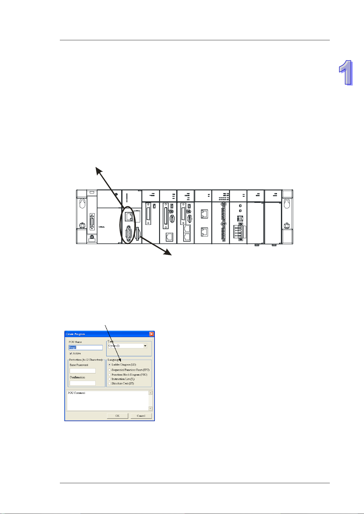
An AH500 series CPU module is a medium type of advanced controller with built-in communication ports. It
provides a strong network function for users, and users can create con nect ion among dev ic es on the network
through software. An AH500 series CPU module also provides structured programming. Users can assign
programs to different tasks, and write a program which is frequently executed in a function block. Besides,
users can choose different programmin g l anguages (instruction lists (IL), structured text s (S T ), ladder diagrams
(LD), sequential function charts (SFC), and function block diagrams (FBD)) dealt with by IEC 61131-3
according to their needs when writing programs. They can create the AH500 hardware co nfiguration by means
of hardware configuration sof t ware. They can also restore or back up a system rapidly through the built-in SD
interface in an AH500 series CPU module. This manual intr o duce s the basi c operat ion of an AH500 system,
and help users familiarize themselves with the AH500 system.
1-8
Page 22
programs to different tasks, and write a program
create connection among devices in the network through software.
module.
according to their needs when writing program.
configuration software.
An AH500 series CPU module also provides
structured programming. Users can assign
which is frequently executed in a function block.
An AH500 series CPU module is a medium type of advanced controller with built-in
communication ports. It provides a strong network function for users, and users can
Chapter 1 Introduction
Users can re store or back up a system rapidly through the built-in SD interface in an AH500 series CPU
With ISPSoft, users can choose different programming
languages (instruction lists (IL), structured texts (ST), ladder
diagrams (LD), sequential function charts (SFC), and
function block diagrams (FBD) dealt with by IEC 61131-3
Users can create an AH500 hardware
configuration by means of the hardware
1-9
Page 23
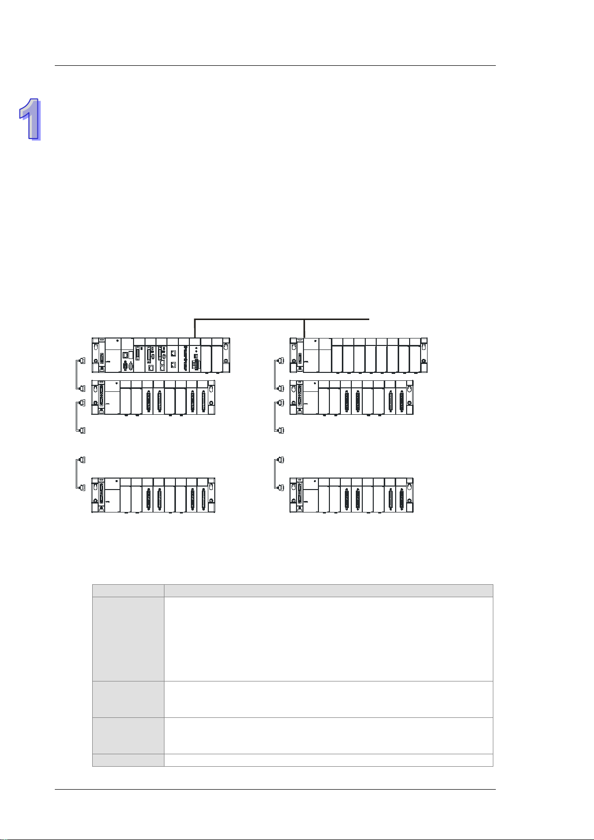
AH500 Operation Manual
7 backplanes
} }
.
.
.
.
.
.
.
.
.
.
.
.
...
Remote I/O
7 backplanes
Module
Description
Digital input/output
AH16AP11P-5A. and AH16AR10N-5A
Analog
module
Analog input/output
AH08DA-5B, AH08DA-5C, and AH06XA-5A
module
Motion
Controlling the motion
1.3 Characteristics
1. High efficiency
AH500 basic series CPU module: A 32-bit high-speed processor is used. The instructions ar e
executed at a speed of 3K steps/ms. (Fifty percent of the instructions are basic instructions, and fifty
percent of the instructions are applied instructions.)
AH500 advance series CPU module: A 32-bit high-speed processor is used. The instructions are
executed at a speed of 12K steps/ms. (Fifty percent of the instructions are basic instructions, and fifty
percent of the instructions are applied instructions.)
2. Supporting more inputs and outputs
The AH500 series CPU module supports up to 4,352 local digital I/O or 544 analog I/O.
A complete AH500 system consists of eight backplanes at most, including a main backplane. Twelve
I/O modules at most can be installed on a main backplane, and eight I/O modules at most can be
installed on an ex tension backplane. Therefore, for the AH500 series CPU, sixty-eight digital
input/output modules at most or sixty-eight analog input/output modules at most can be inst alle d.
Eight RTU modules at most can be installed on the main backplane.
3. Multiple I/O modules
1-10
The I/O module s s upp ort ed by the AH500 seri es CP U module are digit al in put/output modules, a nal og
input/output modules, temperature measurement modules, network modules, mot ion c ontr o l m odul es,
and RTU modules.
AH16AM10N-5A, AH32AM10N-5A, AH32AM10N-5B, AH32AM10N-5C,
Digital
input/output
module
input/output
Temperature
measurement
AH64AM10N-5C, AH16AM30N-5A, AH16AN01R-5A, AH16AN01T-5A,
AH16AN01P-5A, AH32AN02T-5A, AH32AN02T-5B, AH32AN02T-5C,
AH32AN02P-5A, AH32AN02P-5B, AH32AN02P-5C, AH64AN02T-5C,
AH64AN02P-5C, AH16AN01S-5A, AH16AP11R-5A, AH16AP11T-5A,
AH04AD-5A, AH08AD-5A , AH08AD-5B, AH08AD-5C, AH04DA-5A, AH08DA-5A
Measuring the temperature
AH04PT-5A, AH08PTG-5A, AH04TC-5A, and AH08TC-5A
Page 24
Chapter 1 Introduction
Module
Description
module
AH20MC-5A
Extending the communication interface (*There are multiple interfaces. All
AH10PFBS-5A, AH10PFBM-5A, and AH10COPM-5A
AHRTU-DNET-5A , AHRTU-PFBS-5A, and AHR TU-ETHN-5A.
b0b5b10
D0
b15
b0b5b10
X0
b15
control
Network
module
Remote I/O
module
AH02HC-5A, AH04HC-5A, AH05PM-5A, AH10PM-5A, AH15PM-5A, and
network modules can be installed on the main backplane except AH10SCM-5A
and AH15SCM-5A.)
AH10EN-5A, AH15EN-5A, AH10SCM-5A, AH15SCM-5A, AH10DNET-5A,
It is installed on the main backplane as a remote terminal unit. (*It supports
multiple communication interfaces.)
4. Larger program capacity and memory
Program capacity
AH500 basic series CPU module (AHCPU500/510/520/530): 32/64/128/256K steps.
AH500 advanced series CPU module (AHCPU501/511/521/531): 48/96/192/384K steps.
Providing with a wider module selection for users to select a suitable CPU module according to their
program capacity needs.
Memory
AH500 basic series CPU module (AHCPU500/510/520/530): 16/32/64K words of memory and
64/256/512/1024 function blocks to be declared.
AH500 advanced series CPU module (AHCPU501/511/521/531): 24/48/96/128K words of memory
and 512/1024/2048/4096 function blocks to be declared.
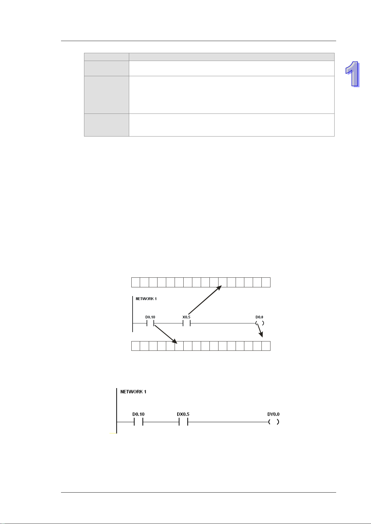
5. Devices which can be used conveniently in a program
An AH500 series CPU module is equ ipped w ith devi ces which can be used convenie ntly in a program.
Users can flexibly specify a bit in a word dev ice, e. g. D0.0, X0.0, and Y0.0. Owing to that bit s in a w ord
device can be specified, these bits can function as cont act s and coils.
Users can access the state of DX0.0 and that of DY0.0 in a program. The state of DX0.0 and that of
DY0.0 are not limited by scan time. They are refreshed immediately in a program.
1-11
Page 25
AH500 Operation Manual
6. Supporting IEC 61131-3
The AH500 series CPU module supports IEC 61131-3.
The programming languages which are supported are instruction lists (IL), structured texts (ST),
ladder diagrams (LD), sequential function charts (SFC), and function block diagrams (FBD).
Users can select a programming language according to their preference and the convenience. The
programming languages supp ort one another so that the pro gr am s writ ten by dif f er ent us er s are
related.
7. Strong function block
Not only the standard IEC61131-3 function blocks are supported, but also the convenient function
blocks provided by Delta Electronics, Inc. are supported. Users can write the program frequently
executed in a function blo ck so that t he program becomes more str u ctur ed a nd can be executed more
conveniently.
The symbol for a function block in a ladder diagram is like an Integrated circuit (IC) in a cir c uit d iagram.
Owing to the fact that the ladder diagram is based on the traditional circuit diagram, the operation of a
function block is quit e similar t o the fun ctio n of an i ntegr ated circuit. Users only need to send the signal
to the corresponding input of the function blo ck, and they ca n receive the signal or state which is
required. During the whole process, users do not need to consider the processing procedure inside
the function block.
1-12
Page 26

Chapter 1 Introduction
A function block i s a progr am element equipp ed with the oper ation f unction . It is sim ilar to a subro utine,
and is a type of POU (Program Organization Unit). It can not operate by itself, and has to be called
through the program POU. After the related parameters are transmitted, the function defined by a
function block is executed. Besides, the final operation result can be sent to the device or variable
used in the superior POU after the execution of the function block is complete.
The setting of passwords by means of ISPSoft provides the secrecy of function blocks for speci al
businesses. The program inside a function block can not be learned, and the patent of a business will
not be infringed.
8. Task
The programs can be assigned to 283 tasks at most. Among the 288 tasks, 32 tasks are cyclic tasks,
32 tasks are I/O interrupts, 4 tasks are timer interrupts, 2 tasks are communication interrupts, 1 task is
an external 24 V low-voltage interrupt, and 212 tasks are user-defined tasks.
Users can enable and disable a task during the execution of a program by means of TKON and
TKOFF.
9. Increasing the efficiency of configuring the hardware through an USB cable and ISPSoft
The AH500 series CPU module provides a standard USB 2.0 interface. USB 2.0 increases the data
transfer rate, and decreases the time it takes to download the program, monitor the program and
configure the hardware. Besides, users do not need to buy a communication cable for the CPU
module. They can use a general USB cable to connect to the AH500 series CPU module.
1-13
Page 27
AH500 Operation Manual
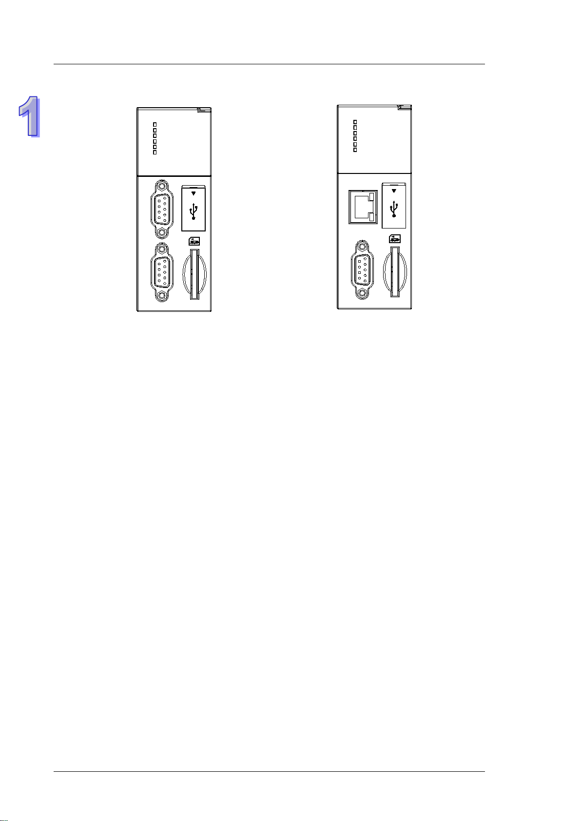
CPU530-RS2
RUN
ERROR
BUS FAULT
SYSTEM
COM1
COM2
C
O
M
C
O
M
2
1
USB
CPU530-EN
RUN
ERROR
BUS FAULT
SYSTEM
COM
Ethernet
COM
USB
10. Serial control interface with multiple functions
AHCPU500/501/510/511/520/521/530/531-RS2 provides two DB9 serial control interfaces, i.e. COM1
and COM2.
AHCPU500/501/510/511/520/521/530/531-EN provides one DB9 serial control interface, i.e. COM.
Users can set the DB9 serial control interface to RS-232, RS-485, or RS-422 according to the
application environment. The data transfer rate can be increased from 9600 bps to 1 Mbps.
AH500 basic series CPU module (AHCPU500/510/520/530): After users set the PLC Link in
NWCONIFG in ISPSoft, they can exchange the data with a device through the RS-485 serial control
interface, and do not need to write any program.
AH500 advanced series CPU module (AHCPU501/511/521/531): After users set the PLC Link in
HWCONIFG in ISPSoft, they can exchange the data with a device through the RS-485 serial control
interface, and do not need to write any program.
11. High-speed Ethernet communication interface
AHCPU500/501/510/511/520/521/530/531-EN is equipped with a 10/100 M Ethernet communication
interface, and supports emails, webs, and socket services.
AH500 basic series CPU module (AHCPU500/510/520/530): After users set the PLC Link in
NWCONIFG in ISPSoft, they can exchange the data with a device network through the Ethernet
communication interface, and do not need to write any program.
AH500 advanced series CPU module (AHCPU501/511/521/531): After users set the PLC Link in
HWCONIFG in ISPSoft, they can exchange the data with a device through the Ethernet
communication interface, and do not need to write any program.
The statu s or the error messa ge rela ted t o the sy stem is se nt to us ers’ email box es immediately. Users
do not need to be on the spot to understand the problem.
12. Memory card
The memory card has the following functions.
System backup: The user program, the CPU parameters, the module table, the setting value in the
device
System recovery: The user program, the CPU parameters, the module table, and the setting value in
the device
Parameter storage: The value in the device
Log storage: The system error log and the system status log
1-14
Page 28

Chapter 1 Introduction
13. Hot swap
The AH500 series I/O modules support the on-line uninterruptible hot swap. When the system runs,
users can replace the module which breaks down without disconnecting the module. After the module
is replaced, the new module runs normally. Users do not need to set the module manually or switch
the state.
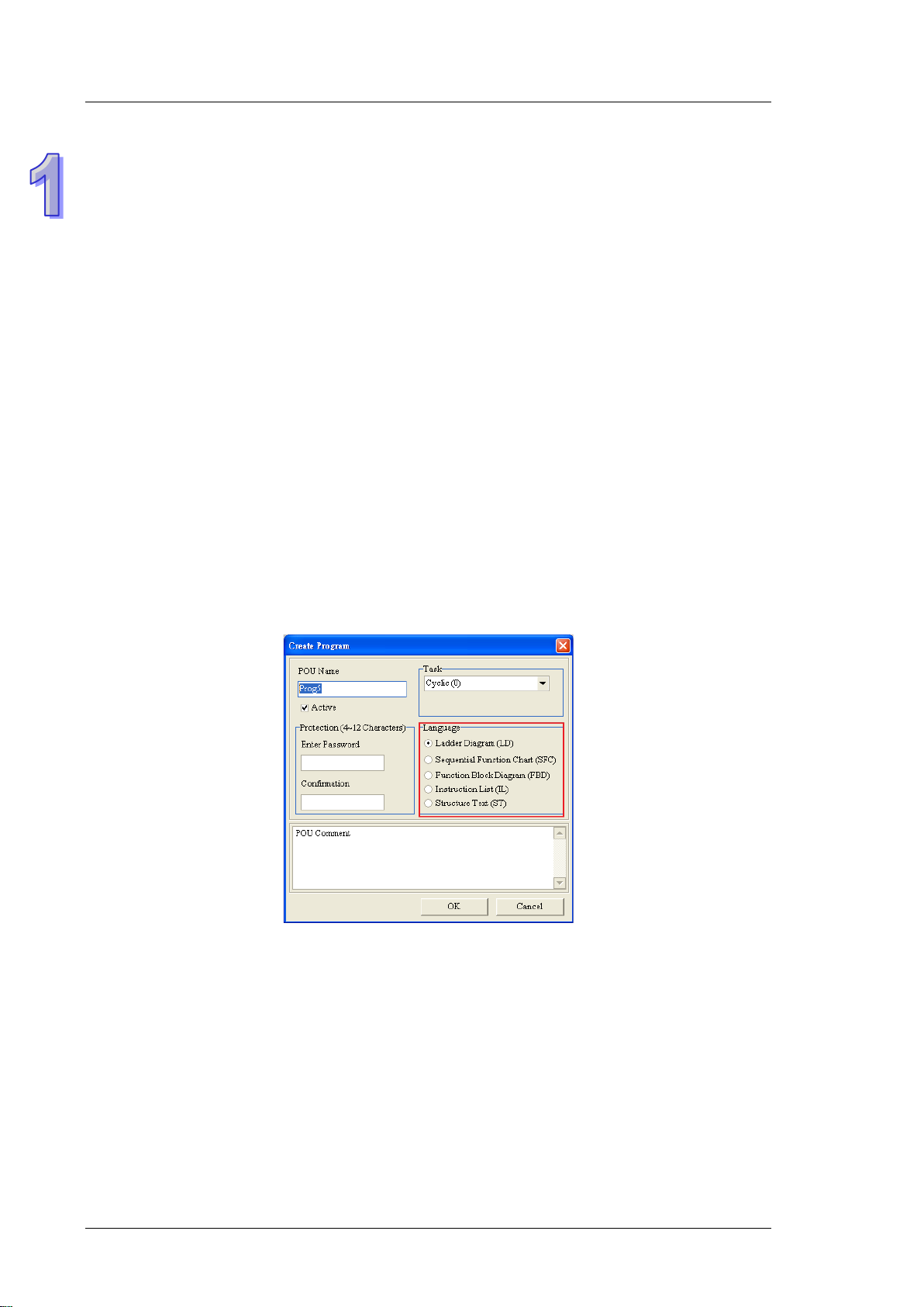
14. Supporting the on-line debugging mode
After a single instruction step has been complete, or after a breakpoint is specified, users can easily
find the bug in the program by means of the on-line debugging mode supported by the AH500 series
CPU module.
If users want to enter the debugging mode, the CPU module must run. After users enable the on-line
monitoring function, they have to click
language to programming language, but the same operat io n appl ies t o the se programming languages.
For the AH500 series PLC, structured texts do not support the debugging mode, and sequential
function charts support the de bugging mode during the action and the transiti on.
Step 1: Setting the PLC to RUN
. The debugging screen varies from programming
1-15
Page 29

AH500 Operation Manual
Step 2: Entering the on-line mode
Step 3: Entering the debugging mode
15. Supporting the on-line editing mode
When the system runs, users can make use of the on-line ed iting m ode to u pdate the program w ithout
affecting the operation of the system.
When the system is in the on-line monitoring mode, users can enter the on-line editing mode by
clicking .
1-16
Page 30

Chapter 1 Introduction
After the program is modified and compiled, users can update the program in the CPU module by
clicking .
1-17
Page 31

AH500 Operation Manual
MEMO
1-18
Page 32

Chapter 2 Specifications and System
Configuration
Table of Contents
2.1 General Specifications ........................................................................................ 2-3
2.2 Specifications for CPU Modules .......................................................................... 2-3
2.2.1 Performance Specifications ......................................................................... 2-3
2.2.2 Profiles ........................................................................................................ 2-6
2.3 Basic System Configuration ................................................................................ 2-8
2.3.1 Introduction ................................................................................................. 2-8
2.3.2 Configuring a Main Backplane .................................................................... 2-9
2.3.3 Configuring an Extension Backplane ......................................................... 2-10
2.3.4 Maximum Extension .................................................................................. 2-10
2.4 Specifications for Digital Input/Output Modules ................................................. 2-11
2.4.1 General Specifications .............................................................................. 2-11
2.4.2 Profiles ...................................................................................................... 2-14
2.4.3 Dimensions ............................................................................................... 2-22
2.4.4 Arrangement of Input/Output Terminals ..................................................... 2-27
2.5 Specifications for Analog Input/Output Modules ................................................ 2-35
2.5.1 General Specifications .............................................................................. 2-35
2.5.2 Profiles ...................................................................................................... 2-39
2.5.3 Dimensions ............................................................................................... 2-41
2.5.4 Arrangement of Input/Output Terminals ..................................................... 2-41
2.5.5 Setting Parameters ................................................................................... 2-43
2.6 Specifications for Temperature Measurement Modules ..................................... 2-46
2.6.1 General Specifications .............................................................................. 2-46
2.6.2 Profiles ...................................................................................................... 2-48
2.6.3 Dimensions ............................................................................................... 2-50
2.6.4 Arrangement of Input/Output Terminals ..................................................... 2-51
2.6.5 Setting Parameters ................................................................................... 2-52
2.7 Specifications for Network Modules .................................................................. 2-53
2.7.1 General Specifications .............................................................................. 2-53
2.7.2 Profiles ...................................................................................................... 2-56
2.7.3 Dimensions ............................................................................................... 2-65
2.7.4 Arrangement of Input/Output Terminals ..................................................... 2-68
2.7.5 Setting Parameters ................................................................................... 2-69
2.8 Specifications for Motion Control Modules ........................................................ 2-72
2.8.1 General Specifications .............................................................................. 2-72
2.8.2 Profiles ...................................................................................................... 2-83
2.8.3 Dimensions ............................................................................................... 2-89
2.8.4 Arrangement of Input/Output Terminals ..................................................... 2-92
2.8.5 Setting Parameters ................................................................................... 2-97
2.9 Specifications for Remote Input/Output Modules .............................................. 2-99
2.9.1 General Specifications .............................................................................. 2-99
2.9.2 Profiles .................................................................................................... 2-100
2.9.3 Dimensions ............................................................................................. 2-104
2.10 Specifications for Power Supply Modules .................................................... 2-106
2.10.1 General Specifications......................................................................... 2-106
2.10.2 Profiles ................................................................................................ 2-107
2.10.3 Dimensions ......................................................................................... 2-108
2.10.4 Arrangement of Te rminals ................................................................... 2-109
2.11 Space Module, Backplanes, and Extension Cables ..................................... 2-110
2-1
Page 33

2.11.1 General Specifications ......................................................................... 2-110
2.11.2 Profiles................................................................................................. 2-111
2.11.3 Dimensions .......................................................................................... 2-114
2-2
Page 34

AH500 Operation Manual
Item
Specifications
Operating temperature
-20~60°C
Storage temperature
-40~70°C
5~95%
No condensation
5~95%
No condensation
Vibration/Shock
resistance
International standar ds IEC 61131-2, IEC 68-2-6 (TEST Fc)/
IEC 61131-2 & IEC 68-2-27 (TEST Ea)
Work environment
No corrosive gas exists.
Installation location
In a control box
Pollution degree
2
AHCPU500/510/520/530
-RS2
AHCPU500/510/520/530
-EN
Execution
The program is executed cyclically.
direct outputs.
IEC 61131-3
Ladder diagrams, function block diagrams,
function charts
Instruction execution speed
3K Steps/ms
Number of instructions
Approximately 666 instructions
1-32000
millisecond.)
256K steps (AHCPU530)
Installation
DIN rails or screws
Installation of a module
A module is installed directly on a backplane.
Connection between two
backplanes
12 (AHCPU500)
68 (AHCPU530)
extension backplanes)
283 tasks (32 cyclic tasks; 32 I/O interrupts; 4
timed interrupts; 2 communication interrupts; 1
2.1 General Specifications
Operating humidity
Storage humidity
2.2 Specifications for CPU Modules
2.2.1 Performance Specifications of AH500 basic series
Item
Input/Output control
Programming language
Constant scan cycle (ms)
Program capacity (step)
Regenerated inputs/out puts
Direct inputs/output s
instruction lists, structured texts, and sequential
(The scan cycle can be increased by one
32K steps (AHCPU500)
64K steps (AHCPU510)
128K steps (AHCPU520)
An extension cable connects two backplanes.
Remark
The inputs and
outputs can be
controlled through the
direct inputs and
Setting the parameter
Maximum number of
modules which can be
installed
Maximum number of
backplanes which can be
connected
Number of tasks
20 (AHCPU510)
36 (AHCPU520)
AHCPU500: 1 backplane (1 main backplane)
AHCPU510: 2 backplanes (1 main backplane+1
extension backplane)
AHCPU520: 4 backplanes (1 main backplane+3
extension backplanes)
AHCPU530: 8 backplanes (1 main backplane+7
2-3
Page 35

Chapter 2 Specifications and System Configuration
AHCPU500/510/520/530
-RS2
AHCPU500/510/520/530
-EN
external 24 V low-voltage interrupt; 212 external
interrupts)
Number of
module
AHCPU500: 1024 (X0.0~X63.15)
AHCPU530: 8192 (X0.0~X511.15)
AHCPU530: 8192 (Y0.0~Y511.15)
Internal relays [M]
8192 (M0~M8191)
AHCPU530: 65536 (L0~L65535)
Timers [T]
2048 (T0~T2047)
Counters [C]
2048 (C0~C2047)
32-bit counter [HC]
64 (HC0~HC63)
AHCPU530: 65536 (D0~D65535)
Stepping relay [S]
2048 (S0~S2047)
Index register [E]
32 (E0~E31)
Special auxiliary relay [SM]
2048 (SM0~SM2047)
Special data register [SR]
2048 (SR0~SR2047)
Two
422
communication ports
One
communication port
Ethernet port
-
10/100 M
MODBUS TCP Slave
Connection Number
AHCPU500-EN: 16
AHCPU530-EN: 128
USB port
Mini USB
Storage interface
SD Card (SD 1.0)
Remote RUN/STOP
The setting range is X0.0~X511.15.
Years, months, days, hours, minutes, seconds, and
weeks
AHCPU501/511/521/531-
AHCPU501/511/521/531
-EN
Execution
The program is executed cyclically.
Regenerated inputs/out puts
Direct inputs/output s
The inputs and
outputs can be
Item
Number of inputs/outputs
Input relays [X]
Output relays [Y]
Link registers [L]
AHCPU500: 768
AHCPU510: 1280
AHCPU520: 2304
AHCPU530: 4352
AHCPU510: 2048 (X0.0~X127.15)
AHCPU520: 4096 (X0.0~X255.15)
AHCPU500: 1024 (Y0.0~Y63.15)
AHCPU510: 2048 (Y0.0~Y127.15)
AHCPU520: 4096 (Y0.0~Y255.15)
AHCPU500: 16384 (L0~L16383)
AHCPU510: 32768 (L0~L32767)
AHCPU520: 65536 (L0~L65535)
Remark
inputs/outputs
accessible to an
actual input/output
AHCPU500:16384 (D0~D16383)
Data register [D]
Serial communication port
MODBUS TCP Master
Connection Number
Real-time clock
AHCPU510: 32768 (D0~D32767)
AHCPU520: 65536 (D0~D65535)
RS-232/RS-485/RS-
32
RS-232/RS-485/RS-422
AHCPU510-EN: 32
AHCPU520-EN: 64
2.2.2 Performance Specifications of AH500 advanced series
Item
Input/Output control
2-4
RS2
Remark
Page 36

AH500 Operation Manual
AHCPU501/511/521/531-
AHCPU501/511/521/531
-EN
controlled through the
direct outputs.
IEC 61131-3
Ladder diagrams, function block diagram s,
function charts
Instruction execution speed
12K Steps/ms
Number of instructions
Approximately 666 instructions
millisecond.)
48K Steps (AHCPU501)
384K Steps (AHCPU531)
Installation
DIN rails or screws
Installation of a module
A module is inst al led dire ctly on a backplane.
Connection between two
backplanes
12 (AHCPU501)
68 (AHCPU531)
AHCPU501: 1 backplane
extension backplanes)
interrupts)
Number of
module
AHCPU531: 16384 (X0.0~X1023.15)
AHCPU501: 2048 (Y0.0~Y127.15)
AHCPU531: 16384 (Y0.0~Y1023.15)
Internal relays [M]
8192 (M0~M8191)
AHCPU501: 24576 (L0~L24575)
AHCPU531: 131072 (L0~L131071)
Timers [T]
2048 (T0~T2047)
Item
Programming language
Constant scan cycl e (ms)
Program capacity (step)
Maximum number of
modules which can be
installed
RS2
instruction lists, structured texts, and sequential
1-32000
(The scan cycle can be increased by one
96K Steps (AHCPU511)
192K Steps (AHCPU521)
An extension cable connects two backplanes.
20 (AHCPU511)
36 (AHCPU521)
Remark
direct inputs and
Setting the parameter
Maximum number of
backplanes which can be
connected
Number of tasks
Number of inputs/outputs
Input relays [X]
Output relays [Y]
AHCPU511: 2 backplanes (1 main backplane+1
extension backplane)
AHCPU521: 4 backplanes (1 main backplane+3
extension backplanes)
AHCPU531: 8 backplanes (1 main backplane+7
283 tasks (32 cyclic tasks; 32 I/O interrupts; 4
timed interrupts; 2 communication interrupts; 1
external 24 V low-voltage interrupt; 212 external
AHCPU501: 768
AHCPU511: 1280
AHCPU521: 2304
AHCPU531: 4352
AHCPU501: 2048 (X0.0~X127.15)
AHCPU511: 4096 (X0.0~X255.15)
AHCPU521: 8192 (X0.0~X511.15)
AHCPU511: 4096 (Y0.0~Y255.15)
AHCPU521: 8192 (Y0.0~Y511.15)
inputs/outputs
accessible to an
actual input/output
Link registers [L]
AHCPU511: 49152 (L0~L49151)
AHCPU521: 98304 (L0~L98303)
2-5
Page 37

Chapter 2 Specifications and System Configuration
AHCPU501/511/521/531-
AHCPU501/511/521/531
-EN
Counters [C]
2048 (C0~C2047)
32-bit counter [HC]
64 (HC0~HC63)
AHCPU501: 24576 (D0~D24575)
AHCPU530: 65536 (D0~D65535)
Stepping relay [S]
2048 (S0~S2047)
Index register [E]
32 (E0~E31)
Special auxiliary relay [SM]
4096 (SM0~SM4095)
Special data register [SR]
4096 (SR0~SR4095)
Two
422
communication ports
One
communication port
Ethernet port
-
10/100 M
MODBUS TCP Slave
Connection Number
AHCPU501-EN: 16
AHCPU531-EN: 128
USB port
Mini USB
Storage interface
SD Card (SD 2.0)
Remote RUN/STOP
The setting range is X0.0~X511.15.
Years, months, days, hours, minutes, seconds, and
weeks
CPU530-EN
RUN
ERROR
BUSFAULT
SYSTEM
COM
Ethernet
COM
USB
Ethernet
COM
1
2
3
4
7
8
9
10
5
6
Item
Data register [D]
Serial communication port
MODBUS TCP Master
Connection Number
RS2
AHCPU500:16384 (D0~D16383)
AHCPU510: 32768 (D0~D32767)
AHCPU520: 65536 (D0~D65535)
RS-232/RS-485/RS-
RS-232/RS-485/RS-422
32
AHCPU511-EN: 32
AHCPU521-EN: 64
Remark
Real-time clock
2.2.3 Profiles
An AH500 system can be configured by setting the following communication ports.
Three built-in communi cati on ports (USB port, RS-232C/RS-422A/RS-485 port, and Ethernet port)
AHCPU5X0-EN (AHCPU500-EN/ AHCPU510-EN/ AHCPU520-EN/ AHCPU530-EN)
AHCPU5X1-EN (AHCPU501-EN/ AHCPU511-EN/ AHCPU521-EN/ AHCPU531-EN)
2-6
Page 38

AH500 Operation Manual
CPU530-RS2
RUN
ERROR
BUS FAULT
SYSTEM
COM1
COM2
C
O
M
C
O
M
2
1
USB
C
O
M
C
O
M
2
1
11
1. Model name
2. LED indicator
3. USB port
4. Ethernet port (for AHCPU5xx-EN)
5. COM
6. SD slot
7. DIP switch
8. RST button
9. CLR button
10. RUN/STOP switch
11. CO M2 (for AHCPU5xx-RS2)
Number
Name
Description
1
Model name
Model name of the CPU module
Operating status of the CPU module
Blinking: The user program is in a debugging mode.
Blinking: A slight error occurs in the system.
Error status of the I/O bus
Blinking: A slight error occurs in the I/O bus.
cleared.
COM LED
indicator
3
USB port
4
Ethernet port
Two built-in communication ports (RS-232C port and RS-422A/RS-485 port)
AHCPU5X1-RS2 (AHCPU501-RS2/ AHCPU511-RS2/ AHCPU521-RS2/ AHCPU531-RS2)
2
RUN LED
indicator
ERROR LED
indicator
BUS FAULT
LED indicator
SYSTEM LED
indicator
indicator
COM1 LED
indicator
COM2 LED
ON: The user program is being executed.
OFF: The execution of the user program stops.
Error status of the CPU module
ON: A serious error occurs in the system.
OFF: The system is normal.
ON: A serious error occurs in the I/O bus.
OFF: The I/O bus is normal.
System status of the CPU module
ON: The external input/output is forced ON/OFF.
OFF: The system is in a default status.
Blinking: The CPU module is being reset./The value in the device is being
Communication status of the communication port
OFF: There is no communication through the communication port.
Blinking: There is communic ati on thro ugh the communication port.
Providing the mini USB communication interface
Providing the Ethernet communication interface (for AHCPU5xx-EN)
2-7
Page 39

Chapter 2 Specifications and System Configuration
Number
Name
Description
5
COM
Providing the RS-232/RS-485/RS-422 communication interface
6
SD slot
Providing the SD interface
ON: Write protection
OFF: No action (default)
card to the CPU module.)
memory card.)
It is used with SW3.
backed up.
need to execute ISPSOFT.exe to set the module table in HWCONFIG.
9
CLR button
Clearing the value in the latched device
switch
STOP: The execution of the us er progr am stops.
Providing the RS-232/RS-485/RS-422 communication interface
(for AHCPU5xx-RS2)
Function which the system executes
OFF: No action (default)
SW1
ON: The system is restored when the CPU module is supplied with
SW2
powered. (The user program, the CPU paramter, the module table,
and the setting values in the devices are restored from the memory
7 DIP switch
8 RST button
10
11 COM1/COM2
RUN/STOP
OFF: No action (default)
ON: It is used with the CLR button to backup the system. (The user
SW3
SW4
Resetting the CPU module, and restoring it to the default factory value
P.S. After the CPU module is reset, the ERROR LED indicator is ON, and the
RUN: The user program is executed.
program, the CPU paramter, the module table, and the setting
values in the devices are backupped from the CPU module to the
OFF: When the system is backed up, the values in the devices are
backed up.
ON: When the system is backed up, the values in the devices are not
error code 16#1402 is shown. To make the PLC operate normally, users
2.3 Basic System Configuration
2.3.1 Introduction
The AH500 system configuration is composed of a CPU module, power supply modules, digital input/output
modules, analog input/output modules, temperature measurement modules, network modules, motion control
modules, a main backplane, extension cables, and extension backplanes. Besides, an SD card is optionally
used.
A main backpla ne can be conn ecte d to an extension backplane through the interface on the left side of the
main backplane, the interface on the left side of the extension backplane, and a Delta extension cable. For a
CPU module or a RTU, a main backplane can be connected to seven extension backplanes at most through
the interfaces on the backplan es. Therefore, if there is a CPU module and t h ere are s ev er al R TUs, not only the
CPU module can be connected to seven extension backplanes, but also every RTU can connect to seven
extension backplanes.
There are two ports on an extensio n bac kp lane . The upper port is used to connect to a superior backplane, and
the lower port is used to connect to an inferior backplane.
2-8
Page 40

AH500 Operation Manual
POWER CPU
I/O0 I/O1 I/O2 I/O3 I/O4 I/O5 I/O6 I/O7
Extension backplane 2
Extension backplane 1
Extension cable
Main backplane
2.3.2 Configuring a Main Backplane
A CPU module, a power supply module, and I/O modules are installed on a main backplane. Twelve I/O
modules at most can be installed on a main backplane.
2-9
Page 41

Chapter 2 Specifications and System Configuration
POWER I/O0 I/O1 I/O2 I/O3 I/O4 I/O5 I/O6 I/O7
Extension
Maximum Extension
Description
A main backplane is
One main backplane and seve n ex tension
backplanes.)
Sixty-eight I/O modules at most
2.3.3 Configuri ng an Extension Backpla ne
An extension backplane can be connected to a main backplane to increase the number of I/O modules. Eight
I/O modules at most can be installed on an extension cable, and seven extension backplanes at most can be
connected to a main backplane.
2.3.4 Maximum Ext ension
Twelve I/O modules at most can be installed on a main backplane. (There are four types of main backplanes.
These four types are four-slot main backplanes, six-slot main backplanes, eight-slot main backplanes, and
twelve-slot main backplanes.) Eight I/O modules at most can be installed on an extension backplane, and
seven extension backplanes at most can be connected to a main backplane. (There are two types of extension
backplanes. These two types are six-slot extension backplanes, and eig ht-s lot extension backplanes.)
Sixty-eight I/O modules at most can be installed on backplanes. Eight AH10EN-5A modules at most can be
installed on a main ba ckplane, and eight AH10DNET-5A modules at most can be installed on a main backplane.
The other I/O modules can be installed on a main backplane unli mit edly . Be sid es, dig ital input/output modules,
analog input/output modules, temperature measurement modules, and AHSCM-5A modules can be installed
on an extension backplane. The other I/O modules can not be installed on an extension backplane.
connected to extension
backplanes
backplanes (There are four types of main
backplanes. These four types are
four-slot main backplanes, six-slot main
backplanes, eight-slot main backplanes,
and twelve-slot main backplanes. There
are two types of extension backplanes.
These two types are six-slot extension
backplanes, and eight-slot extension
can be installed on backplanes.
2-10
Page 42

AH500 Operation Manual
Configuration
Description
There is one main backplane in an AH500 system.
Twelve-slot main backplane: AHBP12M1-5A
There are seven extension backplanes at most in an AH500 system.
Eight-slot extension backplanes: AHBP08E1-5A
There are four types of lengths.
AHACAB30-5A: 3 m
are 1.5 A.)
There is one CPU module in an AH500 system, such as AHCPU5X0-RS2,
AHCPU5X0-EN, AHCPU5X1-RS2, and AHCPU5X1-EN.
Digital I/O module
Analog I/O module
Temperature
measurement module
Motion control module
Motion control modules can only be installed on a main backplane.
unlimitedly.
Model
Item
AH16AM10N
-5A
-5A
-5B
AH32AM10N
-5C
-5C
AH16AP11R
-5A
-5A
-5A
Number of inputs
16
32
32
32
64 8 8
8
Removable terminal
block
DB37
connector
Input type
Digital input
Input form
Direct current (sinking or sourcing)
24 V DC
5 mA
24 V DC
3.2 mA
24 V DC
5 mA
Response
AH500 system co nfig ur ati on
Four-slot main backplane: AHBP04M1-5A
Main backplane
Six-slot main backplane: AHBP06M1-5A
Eight-slot main backplane: AHBP08M1-5A
Extension backplane
Extension cable
Power supply module
CPU module
Network module
Six-slot extension backplanes: AHBP06E1-5A
AHACAB06-5: 60 cm
AHACAB10-5A: 1 m
AHACAB15-5A: 1.5 m
Every backplane needs a power supply module. (The voltages of the
alternating currents which can flow into AHPS05-5A range from 85 V to 264 V,
and the direct curr ents which can flow from AHPS05-5A are 5 A. AHPS05-5A is
used with a backplane. The voltages of the direct currents which can flow into
AHPS15-5A are 24 V, and the direct currents which can flow form AHPS15-5A
Digital I/O modules, analog I/O modules, and temperature measurement
modules can be installed in an AH500 system unlimitedly.
Network modules can only be installed on a main backplane s . Eight
AH10EN-5A modules at most can be installed on a main backplane, and eig ht
AH10DNET-5A modules at most can be installed on a main backplane.
However, AHSCM-5A modules can be installed on a main backplane
2.4 Specifications for Digital Input/Output Modules
2.4.1 General Specifications
Electrical specifications for the inputs on digital input/output modules (The signals passing
through the inputs are 24 V DC signals.)
AH32AM10N
Connector type
Input current
Action
level
time
OFF→ON
ON→OFF
OFF→ON
ON→OFF
>15 V DC
<5 V DC
10 ms±10%
15 ms±10%
AH32AM10N
AH64AM10N
AH16AP11T
AH16AP11P
Latch connector Removable terminal block
2-11
Page 43

Chapter 2 Specifications and System Configuration
Model
Item
-5A
-5A
-5B
AH32AM10N
-5C
AH64AM10N
-5C
-5A
-5A
-5A
Maximum input
frequency
Input impedance
4.7 kΩ
7.5 kΩ
4.7 kΩ
Voltage input
Sourcing: The inputs are PNP transistors whose collectors are open collectors.
Electrical isolation
Optocoupler
Input display
When the optocoupler is driven, the input LED indicator is ON.
Model
Item
Number of inputs
16
Connector type
Removable terminal block
Input type
Digital input
Input form
Alternating current
Input current
120 V AC and 4.5 mA; 240 V AC and 9 mA
Action
level
OFF→ON
>79 V AC
ON→OFF
<40 V AC
Response
time
OFF→ON
15 ms
ON→OFF
30 ms
Electrical isolation
Optocoupler
Input display
When the optocoupler is driven, the input LED indicator is ON.
Model
Item
Number of inputs
16
Input power form
Direct current
Connector type
Removable terminal block
Input type
Digital input
Input form
Direct current (sinking or sourcing)
Input current
24 V DC, 5 mA
level
OFF→ON
>15 V DC
ON→OFF
<5 V DC
Response
cycle
OFF→ON
(Typical)
OFF→ON
(Maximum)
ON→OFF
(Typical)
(Maximum)
Input impedance
ON→OFF
Sourcing: The inputs are PNP transistors whose collectors are open collectors.
Electrical isolation
Optocoupler
Input display
When the optocoupler is driven, the input LED indicator is ON.
AH16AM10N
AH32AM10N
AH32AM10N
AH16AP11R
AH16AP11T
AH16AP11P
50 Hz
Input signal
Sinking: The inputs are NPN transistors whose collectors are open collectors.
Electrical specifications for the inputs on a digital input/output module (The signals passing
through the inputs are alternating current signals ranging in voltage from 120 V to 240 V.)
AH16AM30N-5A
Electrical specifications for the inputs on a digital input/output module which supports I/O
interrupts (The signals passing through the inputs are 24 V DC signals.)
AH16AR10N-5A
Action
Filtering
0.1 ms 0.5 ms 3 ms 15 ms 20 ms
0.11 ms 0.51 ms 3.01 ms 15.01 ms 20.01 ms
time
0.12 ms 0.52 ms 3.02 ms 15.02 ms 20.02 ms
0.11 ms 0.51 ms 3.01 ms 15.01 ms 20.01 ms
ON→OFF
0.15 ms 0.55 ms 3.05 ms 15.05 ms 20.05 ms
Voltage input
Input signal
Sinking: The inputs are NPN transistors whose collectors are open collectors.
2-12
Page 44

AH500 Operation Manual
Model
Item
An interrupt is triggered when there is a transition in a signal from low to high/from
high to low/from low to high or from high to low.
Interrupt service
routine
Filtering cycle which
can be set for an input
channel
Model
Item
-5A
-5A
-5A
-5A
AH16AN01P
-5A
-5A
-5A
Number of outputs
16 8 16 8 16 8 16
Connector type
Removable terminal block
Output type
Relay-R
Transistor-T (sinking)
Transistor-P (sourcing)
TRIAC-S
250 V AC, and below
30 V DC
2 A/output
(5 A/COM)
0.5 A/output
(4 A/COM)
0.5 A/output
(4 A/COM)
(2 A/COM)
Not
applicable
20 W (24 V DC)
100 W (230 V AC)
Model
Item
AH32AN02T
-5A
AH32AN02P
-5A
AH32AN02T
-5B
AH32AN02P
-5B
AH32AN02T
-5C
32AN02P
- 5C
AH64AN02T
-5C
AH64AN02P
-5C
Number of outputs
32
32
32
32
32
32
64
64
Removable
terminal block
Transistor-P (sourcing)
Voltage specifications
12~30 V DC*2
Resistance
0.1 A/output (1 A/COM)
Inductance
Not applicable
Bulb
Not applicable
frequency*1
Resistance
100 Hz
Inductance
-
Bulb
-
time
AH16AR10N-5A
Trigger for an interrupt
The interrupt service routine numbers which can be set are in the range of 0 to 31.
0.1 ms, 0.5 ms, 3 ms (default), 15 ms, or 20 ms
Electrical specifications for the outputs on digital input/output modules
AH16AN01R
AH16AP11R
AH16AN01T
AH16AP11T
AH16AP11P
AH16AN01S
Voltage specifications
Resistance
Maximum
load
Inductance Life cycle curve*3 12 W (24 V DC) 12 W (24 V DC)
Bulb
Maximum
output
Resistance 1 Hz 100 Hz 100 Hz 10 Hz
Inductance 0.5 Hz 0.5 Hz 0.5 Hz -
frequency*1
Bulb 1 Hz 10 Hz 10 Hz 10 Hz
Maximum
OFF→ON
Response
time
ON→OFF
Connector type
Output type
12~30 V DC*2 12~30 V DC*2 120/240 V AC
2 W (24 V DC) 2 W (24 V DC) 60 W AC
10 ms 0.5 ms 0.5 ms
AH
DB37 connector Latch connector
Transistor–T (sinking )
0.5 A/output
1 ms+0.5
AC cycles
Maximum
load
Maximum
output
Maximum
OFF→ON
Response
ON→OFF
*1: The scan cycle affects the frequency.
*2: The terminals UP and ZP needs to be connected to the 24 V DC auxiliary power supply (-15%~+20%), and
the rated current consumption is 1 mA/output.
0.5 ms
2-13
Page 45

Chapter 2 Specifications and System Configuration
Contact Current(A)
20
0.5
0.1
0.2
30
50
0.3 0.7
1 2
200
300
500
100
1000
2000
3000
Operation(X10 )
3
120VAC Resistive
30VDC Inductive(t=7ms)
240VAC Inductive(cos 0.4)
ψ
=
120VAC Inductive(cos =0.4)
ψ
30VDC
Inductive
(t=40ms)
L
0
S/S
L
L
L
5
6
L
1
L
L
3
2
4
7
L
UP
ZP
0
24VDC 5mA
24VDC 0.5A
7
6
5
4
3
2
1
0
1 2 453
6
7
0
16AP11T
21 453 6
7
10 3 47562
16AM30N
1
0
4
2
12
8
14
13
15
COM
7
120/240VAC
4.5/9mA
11
9
10
COM
5
3
6
98 12 1513 1410 11
16AN01R
10 43256
7
L
L
L
L
4
5
3
2
L
COM0
12
COM1
L
7
L
L
L
L
L
13
14
15
L
6
11
COM2
24VDC
/240VAC 2A
COM3
L
L
L
8
10
9
L
1
0
1110 1413 15128 9
COM3
1
L
0
L
4
L
L
5
COM0
3
L
L
2
L
8
9
L
L
10
COM1
L
7
11
13
14
L
L
L
15
12
COM2
L
L
L
6
240VAC 0.5A
16AN01S
5
210 43 6
7
98 1413 151110 12
1
3
2
0
S/S
5
6
L
L
L
L
4
7
UP
ZP
L
L
L
L
24VDC 5mA
24VDC 0.5A
0
7
6
5
4
3
2
1
0
1 32 64
5 7
16AP11P
0 2 31 64
5 7
COM1
1
0
10 3 42
765
L
0
L
L
2
1
S/S
6
5
4
3
2
7
3
5
L
L
L
6
7
COM0
L
L
4
24VDC 5mA
240VAC 2A
16AP11R
10 43276
5
1
2
3
4
7
6
8
9
10
5
10
12
11
9
8
6
5
4
3
2
15
14
7
13
S/S
24VDC 5mA
1
0
S/S
7
6
16AM10N
0 2 3154
98 1510 11 12 13 14
11
21 3
109513412
6
7
14 15
0
2
L
L
L
L
L
0
8
1
3
4
16AN01T
9
8
7
6
10
12
13
11
ZP
UP
15
L
L
L
14
L
L
L
L
L
L
L
5
12~24VDC 0.5A
L
11
16AN01P
08192
10513
3 4126
7
1514
L
0
1
3
L
L
4
L
L
2
12~24V DC 0.5A
8
9
L
6
7
L
L
L
10
12
L
L
13
L
L
11
ZP
L
UP
15
L
14
L
5
7
10
12
11
9
8
6
5
4
3
2
15
14
6
7
13
S/S
24VDC 5mA
1
0
16AR10N
0 2 3154
S/S
98 1510 11 12 13 14
Number
Name
Description
1
Model name
Model name of the module
Input/Output LED
indicator
If there is an input signal, the input LED indicator is ON.
If there is an output signal, the output LED indicator is ON.
3
Removable
The inputs are connected to a switch or a sensor.
*3: The life cycle curve is shown below.
2.4.2 Profiles
AH16AM10N-5A/AH16AM30N-5A/AH16AR10N-5A/AH16AN01S-5A/AH16AN01R-5A/AH16AN01T-5A/
AH16AN01P-5A/AH16AP11R-5A/AH16AP11T-5A/AH16AP11P-5A
2-14
2
Page 46

AH500 Operation Manual
Number
Name
Description
terminal block
The outputs are conne cte d to a loa d w hich will b e driven , e.g . a cont act ,
or a solenoid valve.
Arrangement of the
terminals
Description of the
inputs/outputs
6
Label
Nameplate
7
Clip
Fixing the removable terminal block
8
Set screw
Fixing the module
9
Connector
Connecting the module and a backplane
10
Projection
Fixing the module
0 1
12
S/S
S/S
14
13
15
2
7
8
9
11
10
5
4
3
6
0
1
11
12
13
14
15
10
S
/S
S/S
2
7
8
9
3
4
5
6
0
1
8 1413 1510 11 129
24VDC 5mA
8
00
141310 11 12
2 3 54 6194 51 32 61577
32AM10N
10 2 543 64 51 320 6 77
2
3
4
1
5
7
6
0
1
0 1
12~24VDC 0.1A
12
ZP
UP
ZP
13
14
15
UP
2
7
9
8
11
10
3
4
5
6
0
1
12
ZP
ZP
UP
14
13
UP
15
2
7
9
8
11
10
5
4
3
6
1413 1512108 9 11
12~24VDC 0.1A
1461312541028
0 1
9 11315
7
6
5410 2 3
32AN02P
7
0 1
12~24VDC 0.1A
12
ZP
UP
ZP
13
14
15
UP
2
7
9
8
11
10
3
4
5
6
0
1
12
ZP
ZP
UP
14
13
UP
15
2
7
9
8
11
10
5
4
3
6
0
1
1413 1510 11 128 9
12~24VDC 0.1A
14 15
6 7
10 11 12
2 3 4
8
0 1
9 13
5
76
32AN02T
10 2 43 5
Number
Name
Description
1
Model name
Model name of the module
Input/Output LED
indicator
If there is an input signal, the input LED indicator is ON.
If there is an output signal, the output LED indicator is ON.
The inputs are connected to a switch or a sensor.
The outputs are conne cte d to a loa d w hich will b e driven , e.g . a cont act ,
or a solenoid valve.
Description of the
inputs/outputs
5
Set screw
Fixing the module
6
Label
Nameplate
7
Projection
Fixing the module
4
input/output
Arrangement of the terminals
5
Number of inputs/output s and spe cifi cat ion s
AH32AM10N-5A/AH32AN02T-5A/AH32AN02P-5A
2
3
4
Removable
terminal block
Number of inputs/output s and spe cifi cat ion s
2-15
Page 47

Chapter 2 Specifications and System Configuration
32D O-T Sink
12~24VDC 0.1A
32AN02T
32DI-DC
24VDC 5mA
32AM10N
32DO-T Source
12~24VDC 0.1A
32AN02P
2
3
4
5
6
7
8
1
131310 11 128 9
1028
0 1
9 11 12
354
210 543
14 15
14 15
6
7
76
131310 11 128 9
1028
0 1
9 11 12
354
210 543
14 15
14 15
6
7
76
131310 11 128 9
1028
0 1
9 11 12
354
210 543
14 15
14 15
6
7
76
Number
Name
Description
1
Model name
Model name of the module
Input/Output LED
indicator
If there is an input signal, the input LED indicator is ON.
If there is an output signal, the output LED indicator is ON.
3
DB37 connector
It is connected to the I/O extension cable UC-ET010-33B.
Description of the
inputs/outputs
5
Label
Nameplate
6
Set screw
Fixing the module
7
Connector
Connecting the module and a backplane
8
Projection
Fixing the module
24VDC 5mA
77
15
62 3
15491 64532
121110 13 14
00
8
77
32AM10N
60 2 31 54 63 4 520 1
9 121110 1513 148
5
7
2
3
4
1
6
12~24VDC 0.1A
12 1513 14
7645
12 1513 14
6 74 5
9108210
20 1
32AN02P
3
11
11398 10
12~24VDC 0.1A
5
13
9108
432
121110
7
6
1514
5
3 420 1
32AN02T
6 7
98 121110 1513 14
Number
Name
Description
1
Model name
Model name of the module
Input/Output LED
indicator
If there is an input signal, the input LED indicator is ON.
If there is an output signal, the output LED indicator is ON.
It is connected to the I/O extension cable
UC-ET010-24A/UC-ET010-24C.
Description of the
inputs/outputs
5
Set screw
Fixing the module
6
Label
Nameplate
7
Projection
Fixing the module
AH32AM10N-5B/AH32AN02T-5B/AH32AN02P-5B
2
4
Number of inputs/output s and spe cifi cat ion s
AH32AM10N-5C/AH32AN02T-5C/AH32AN02P-5C
2
3 Latch connector
4
Number of inputs/outputs and spe cifi cat ion s
2-16
Page 48

AH500 Operation Manual
2
3
4
5
0
-
3 4
-
7
24VDC 5mA
131310 11 128 9
1028
0 1
9 11 12
354
210 543
64AM10N
14 15
14 15
6
7
76
9
1
6
7
8
10
4-70-3
131310 11 128 9
1028
0 1
9 11 12
3
5
4
210 543
64AN02T
14 15
14 15
6
7
76
12~24VDC 0.1mA
4-70-3
131310 11 128 9
1028
0 1
9 11 12
3
5
4
210 543
64AN02P
14 15
14 15
6
7
76
12~24VDC 0.1mA
4
Number
Name
Description
1
Model name
Model name of the module
indicator
If there is an output signal, the output LED indicator is ON.
LED indicator
switch
Left: High 32 bits
Right: Low 32 bits
UC-ET010-24A/UC-ET010-24C.
Description of the
inputs/outputs
6
Extension port
Updating the firmware
7
Label
Nameplate
8
Set screw
Fixing the module
9
Connector
It connects the module and a backplane.
10
Projection
Fixing the module
2
1
Number
Name
Description
module.
2
Set screw
Fixing the connector
AH64AM10N-5C/AH64AN02T-5C/AH64AN02P-5C
Input/Output LED
2
If there is an input signal, the input LED indicator is ON.
3
4 Latch connector
5
It is connected to the I/O extension cable
Number of inputs/output s and spe cifi cat ion s
DB37 connector, I/O extension cable, and external terminal module
1. I/O extension cable UC-ET010-33B
1 DB37 connector
Connecting a digital input/output module and an external terminal
2-17
Page 49

Chapter 2 Specifications and System Configuration
1
3
4
2
1
3
4
2
1
3
4
2
1
3
4
2
2. External terminal module for AH32AM10N-5B: UB-10-ID32B
3. External terminal modules for AH32AN02T-5B
UB-10-OR32A
UB-10-OT32B
4. External terminal modules for AH32AN02P-5B
UB-10-OR32B
2-18
Page 50

AH500 Operation Manual
1
3
4
2
Number
Name
Description
Connecting the external terminal module and a digital
input/output module
2
Terminals
Input/Output terminals for wiring
3
Clip
Hanging the external terminal module on a DIN rail
4
Set screw
Fixing the base
1
1
1 2
1 2
39 4039 40
Number
Name
Description
Connecting a digital input/output module and the external
terminal module UB-10-ID32A
3
4
2
1
Number
Name
Description
Connecting the external terminal module a nd a digit al
input/output module
2
Terminals
Input/Output terminals for wiring
3
Clip
Hanging the external terminal module on a DIN rail
4
Set screw
Fixing the base
UB-10-OT32B
1 DB37 connector
Latch connector, I/O extension cable, and external terminal module
1. I/O extension cable UC-ET010-24A
1 40-pin IDC connector
2. External terminal module for AH32AM10N-5C/AH64AM10N-5C: UB-10-ID32A
1 40-pin latch connector
2-19
Page 51

3. I/O extension cable UC-ET010-24C
2
1
2
1 2
1 2
1 2
19 20
19 20
39 40
CN1
CN2
CN3
Number
Name
Description
terminal module.
Connecting a digital input/output module and the external
terminal module UB-10-OR16A or UB-10-OR16B
1
1
1 2
1 2
39 4039 40
Number
Name
Description
Connecting a digital input/output module and the external
terminal module UB-10-OT32A
5
7
2
1
3
4
6
Chapter 2 Specifications and System Configuration
1 40-pin IDC connector
Connecting a digital input/output module and an external
2 20-pin IDC connector
4. I/O extension cable UC-ET010-24A
1 40-pin IDC connector
5. External terminal modules for AH32AN02T-5C/AH64AN02T-5C
UB-10-OR16A
2-20
Page 52

AH500 Operation Manual
3
4
2
1
5
7
2
1
3
4
6
3
4
2
1
Number
Name
Description
20-pin latch
connector
Connecting the external terminal module and a digital input/output
module
Output LED
indicator
3
Output relay
Output relay
4
Output terminal
Output terminal for wiring
Power input
terminal
6
Clip
Hanging the external terminal module on a DIN rail
7
Set screw
Fixing the base
UB-10-OT32A
6. External terminal module for AH32AN02P-5C/AH64AN02P-5C
UB-10-OR16B
UB-10-OT32A
1
2
5
If there is an output signal, the output LED indicator is ON.
Power input terminal for wiring
2-21
Page 53

Chapter 2 Specifications and System Configuration
103
35
110
114
L
0
S/S
L
L
L
5
6
L
1
L
L
3
2
4
7
L
UP
ZP
0
24VDC 5mA
24VDC 0.5A
7
6
5
4
3
2
1
0
1 2 453
6
7
0
16AP11T
21 453 6
7
10 3 4756
2
16AM30N
1
0
4
2
12
8
14
13
15
COM
7
120/240VAC
4.5/9mA
11
9
10
COM
5
3
6
98 12 1513 1410 11
16AN01R
10 43256
7
L
L
L
L
4
5
3
2
L
COM0
12
COM1
L
7
L
L
L
L
L
13
14
15
L
6
11
COM2
24VDC
/240VAC 2A
COM3
L
L
L
8
10
9
L
1
0
1110 1413 15128 9
COM3
1
L
0
L
4
L
L
5
COM0
3
L
L
2
L
8
9
L
L
10
COM1
L
7
11
13
14
L
L
L
15
12
COM2
L
L
L
6
240VAC 0.5A
16AN01S
5
210 43 6
7
98 1413 151110 12
1
3
2
0
S/S
5
6
L
L
L
L
4
7
UP
ZP
L
L
L
L
24VDC 5mA
24VDC 0.5A
0
7
6
5
4
3
2
1
0
1 32 64
5 7
16AP11P
0 2 31 64
5 7
COM1
1
0
10 3 42
765
L
0
L
L
2
1
S/S
6
5
4
3
2
7
3
5
L
L
L
6
7
COM0
L
L
4
24VDC 5mA
240VAC 2A
16AP11R
1
0 43276
5
10
12
11
9
8
6
5
4
3
2
15
14
7
13
S/S
24VDC 5mA
1
0
S/S
7
6
16AM10N
0 2 3154
98 1510 11 12 13 14
11
21 3
109513412
6
7
14 15
0
2
L
L
L
L
L
0
8
1
3
4
16AN01T
9
8
7
6
10
12
13
11
ZP
UP
15
L
L
L
14
L
L
L
L
L
L
L
5
12~24VDC 0.5A
L
11
16AN01P
08192
10513
3 4126
7
1514
L
0
1
3
L
L
4
L
L
2
12~24V DC 0.5A
8
9
L
6
7
L
L
L
10
12
L
L
13
L
L
11
ZP
L
UP
15
L
14
L
5
7
10
12
11
9
8
6
5
4
3
2
15
14
6
7
13
S/S
24VDC 5mA
1
0
16AR10N
0 2 31 54
S/S
98 1510 11 12 13 14
0 1
12
S/S
S/S
14
13
15
2
7
8
9
11
10
5
4
3
6
0
1
11
12
13
14
15
10
S
/S
S/S
2
7
8
9
3
4
5
6
0
1
8 1413 1510 11 129
24VDC 5mA
8
00
141310 11 12
2 3 54 6194 51 32 61577
32AM10N
10 2 543 64 51 320 6 77
5
7
6
35
103
110
6
123.4
0
1
0 1
12~24VDC 0.1A
12
ZP
UP
ZP
13
14
15
UP
2
7
9
8
11
10
3
4
5
6
0
1
12
ZP
ZP
UP
14
13
UP
15
2
7
9
8
11
10
5
4
3
6
1413 1512108 9 11
12~24VDC 0.1A
1461312541028
0 1
9 11315
7
6
5410 2 3
32AN02P
7
0 1
12~24VDC 0.1A
12
ZP
UP
ZP
13
14
15
UP
2
7
9
8
11
10
3
4
5
6
0
1
12
ZP
ZP
UP
14
13
UP
15
2
7
9
8
11
10
5
4
3
6
0
1
1413 1510 11 128 9
12~24VDC 0.1A
14 15
6 7
10 11 12
2 3 480 1
9 13
5
76
32AN02T
10 2 43 5
2.4.3 Dimensions
AH16AM10N-5A/AH16AM30N-5A/AH16AR10N-5A/AH16AN01S-5A/AH16AN01R-5A/AH16AN01T-5A/
AH16AN01P-5A/AH16AP11R-5A/AH16AP11T-5A/AH16AP11P-5A
AH32AM10N-5A/AH32AN02T-5A/AH32AN02P-5A
2-22
Unit: mm
Unit: mm
Page 54

AH500 Operation Manual
35
103
110
6
32DI-DC
24VDC 5mA
32AM10N
131310 11 128 9
1028
0 1
9 11 12
354
210 543
14 15
14 15
6
7
76
32D O-T Sink
12~24VDC 0.1A
32AN02T
131310 11 128 9
1028
0 1
9 11 12
354
210 543
14 15
14 15
6
7
76
32DO-T Source
12~24VDC 0.1A
32AN02P
131310 11 128 9
1028
0 1
9 11 12
354
210 543
14 15
14 15
6
7
76
77
15
62 3
15491 64532
121110 13 14
00
8
77
32A 02NP
60 2 31 54 63 4 520 1
9 121110 1513 148
35
103
110
6
12~24VDC 0.1A
24VDC 5mA
77
15
62 3
15491 64532
121110 13 14
00
8
77
32AM10N
60 2 31 54 63 4 520 1
9 121110 1513 148
12~24VDC 0.1A
5
13
9108
432
121110
7
6
1514
5
3 420 1
32AN02T
6 7
98 121110 1513 14
0-3 4-7
24 VDC 5m A
131310 11 128 9
1028
0 1
9 11 12
354
210 543
64AM 10N
14 15
14 15
6
7
76
35
103
110
6
4-70-3
131310 11 128 9
1028
0 1
9 11 12
354
210 543
64AN 02T
14 15
14 15
6
7
76
12~24VDC 0.1mA
4
-
70-3
131310 11 128 9
1028
0 1
9 11 12
354
210 543
64AN 02P
14 15
14 15
6
7
76
12~24VDC 0.1mA
AH32AM10N-5B/AH32AN02T-5B/AH32AN02P-5B
Unit: mm
AH32AM10N-5C/AH32AN02T-5C/AH32AN02P-5C
Unit: mm
AH64AM10N-5C/AH64AN02T-5C/AH64AN02P-5C
Unit: mm
2-23
Page 55

Chapter 2 Specifications and System Configuration
100
113
87
50.8
215
87
39.
4
113
87
50.8
DB37 connector, I/O extension cable, and external terminal module
1. I/O extension cable UC-ET010-33B
Unit: cm
2. External terminal module for AH32AM10N-5B: UB-10-ID32B
Unit: mm
3. External terminal modules for AH32AN02T-5B
UB-10-OR32A
2-24
UB-10-OT32B
Unit: mm
Unit: mm
Page 56

AH500 Operation Manual
215
87
39.
4
113
87
50.8
100
1 2
1 2
39 4039 40
113
87
53.6
4. External terminal modules for AH32AN02P-5B
UB-10-OR32B
Unit: mm
UB-10-OT32B
Unit: mm
Latch connector, I/O extension cable, and external terminal module
1. I/O extension cable UC-ET010-24A
Unit: cm
2. External terminal module for AH32AM10N -5C/AH64AM10N-5C: UB-10-ID32A
Unit: mm
2-25
Page 57

Chapter 2 Specifications and System Configuration
113
87
53.6
113
87
53.6
100
1 2
1 2
1 2
19 20
19 20
39 40
CN1
CN2
CN3
113
87
55.3
3. External terminal module for AH32AN02T-5C/AH64AN02T-5C: UB-10-OT32A
Unit: mm
4. External terminal module for AH32AN02P-5C/AH64AN02P-5C: UB-10-OT32A
Unit: mm
5. I/O extension cable UC-ET010-24C
2-26
Unit: cm
External terminal module for AH32AN02T -5C/AH64AN02T-5C: UB-10-OR16A
Unit: mm
Page 58

AH500 Operation Manual
113
87
55.3
AH16AM10N-5A
AH16AM30N-5A
AH16AR10N-5A
AH16AN01S-5A
7
10
12
11
9
8
6
5
4
3
2
15
14
6
7
13
S/S
24VD C 5mA
1
0
16AM10N
0 2 31
5
4
S/S
98 1510 11 1
2 13 14
10 3 4756
2
16AM30N
1
0
4
2
12
8
14
13
15
COM
7
120/240VAC
4.5/9mA
11
9
10
COM
5
3
6
98 12 1513 1410 11
7
10
12
11
9
8
6
5
4
3
2
15
14
6
7
13
S/S
24VDC
5mA
1
0
16AR10N
0 2 31 54
S/S
98 1510 11 12 13 14
COM3
1
L
0
L
4
L
L
5
COM0
3
L
L
2
L
8
9
L
L
10
COM1
L
7
11
13
14
L
L
L
15
12
COM2
L
L
L
6
240 VAC 0. 5A
16AN01S
5
210 43 6
7
98 1
413 151110 12
External terminal module for AH32AN02P-5C/AH64AN02P-5C: UB-10-OR16B
Unit: mm
2.4.4 Arrangement of Input/Output Terminals
2-27
Page 59

Chapter 2 Specifications and System Configuration
AH16AN01R-5A
AH16AN01T-5A
AH16AN01P-5A
16AN01R
10 432
567
L
L
L
L
4
5
3
2
L
COM0
12
COM1
L
7
L
L
L
L
L
13
14
15
L
6
11
COM2
24VD C
/240VAC 2A
COM3
L
L
L
8
10
9
L
1
0
1110 1413 15128 9
11
21 3
109
5
13412
6
7
14 15
0
2
L
L
L
L
L
0
8
1
3
4
16AN01T
9
8
7
6
10
12
13
11
ZP
UP
15
L
L
L
14
L
L
L
L
L
L
L
5
12~2 4VDC 0 .5A
L
11
16AN01P
0
8
1
9
2
10513
3 4
12
6
7
1514
L
0
1
3
L
L
4
L
L
2
12~2 4VDC 0.5 A
8
9
L
6
7
L
L
L
10
12
L
L
13
L
L
11
ZP
L
UP
15
L
14
L
5
AH16AP11R-5A
AH16AP11T-5A
AH16AP11P-5A
COM1
1
0
10 3 42
765
L
0
L
L
2
1
S/S
6
5
4
3
2
7
3
5
L
L
L
6
7
COM0
L
L
4
24VD C 5m A
240 VAC 2A
16AP11R
10 432
765
L
0
S/S
L
L
L
5
6
L
1
L
L
3
2
4
7
L
UP
ZP
0
24VD C 5m A
24VDC 0.5A
7
6
5
4
3
2
1
0
1 2 453 6
7
0
16AP11T
21 453 6
7
1
3
2
0
S/S
5
6
L
L
L
L
4
7
UP
ZP
L
L
L
L
24VD C 5m A
24VDC 0.5A
0
7
6
5
4
3
2
1
0
1 32 64
5 7
16AP11P
0 2 31 64
5 7
2-28
Page 60

AH500 Operation Manual
AH32AM10N-5A
AH32AN02T-5A
0 1
12
S/S
S/S
14
13
15
2
7
8
9
11
10
5
4
3
6
0
1
11
12
13
14
15
10
S/S
S/S
2
7
8
9
3
4
5
6
0
1
24VDC 5mA
8 1413 1510 11 129
24VDC 5mA
8
00
141310 11 12
2 3 54 61
9
4 51 32 61577
32AM10N
10 2 543 64 51 320 6 77
0.0
1.0
0 1
12~24VDC 0.1A
12
ZP
UP
ZP
13
14
15
UP
2
7
9
8
11
10
3
4
5
6
0
1
12
ZP
ZP
UP
14
13
UP
15
2
7
9
8
11
10
5
4
3
6
0
1
1413 1510 11 128 9
12~24VDC 0.1A
14 15
6 7
10 11 12
2 3 4
8
0 1
9 13
5
76
32AN02T
10 2 43 5
0.0
1.0
0.1
1.1
0.1
1.1
0.2
1.2
0.2
1.2
0.3
1.3
0.3
1.3
0.4
1.4
0.4
1.4
0.5
1.5
0.5
1.5
0.6
1.6
0.6
1.6
0.7
1.7
0.7
1.7
0.8
1.8
0.8
1.8
0.9
1.9
0.9
1.9
0.10
1.10
0.10
1.10
0.11
1.11
0.11
1.11
0.12
1.12
0.12
1.12
0.13
1.13
0.13
1.13
0.14
1.14
0.14
1.14
0.15
1.15
0.15
1.15 - -
UP
UP
- - UP
UP
S/S
S/S
ZP
ZP
S/S
S/S
ZP
ZP
AH32AN02P-5A
AH32AM10N-5B
0
1
0 1
12~24VDC 0.1A
12
ZP
UP
ZP
13
14
15
UP
2
7
9
8
11
10
3
4
5
6
0
1
12
ZP
ZP
UP
14
13
UP
15
2
7
9
8
11
10
5
4
3
6
1413 1512108 9 11
12~24VDC 0.1A
1461312
5410280 1
9 11
3
15
7
6
5410 2 3
32AN02P
7
0.0
1.0
24VDC 5mA
10 2543
76745
1 320 6
8
8
00
1413 1510 11 12
1413 1510 11 12
2 354 6
7
1
9
9
745
1 32 6
32AM10N
0.0
0.1
0.1
1.1
0.2
0.3
0.2
1.2
0.4
0.5
0.3
1.3
0.6
0.7
0.4
1.4
0.8
0.9
0.5
1.5
0.10
0.11
0.6
1.6
0.12
0.13
0.7
1.7
0.14
0.15
0.8
1.8
S/S
S/S
0.9
1.9
NC
1.0
0.10
1.10
1.1
1.2
0.11
1.11
1.3
1.4
0.12
1.12
1.5
1.6
0.13
1.13
1.7
1.8
0.14
1.14
1.9
1.10
0.15
1.15
1.11
1.12
UP
UP
1.13
1.14
UP
UP
1.15
S/S
ZP
ZP
S/S ZP
ZP
2-29
Page 61

Chapter 2 Specifications and System Configuration
AH32AN02T-5B
AH32AN02P-5B
32AN02T
10 2543
7
6
1413 1510 11 12
1413 1510 11 12
2 354 6
7
8
8
0 1
9
9
12~24VDC 0.1A
0.0
0.1
12~24VDC 0.1A
32AN02P
13
13
10 11 128 9
1028
0 1
9 11 12
354
210 543
14 15
14 15
6
7
76
0.0
0.1
0.2
0.3
0.2
0.3
0.4
0.5
0.4
0.5
0.6
0.7
0.6
0.7
0.8
0.9
0.8
0.9
0.10
0.11
0.10
0.11
0.12
0.13
0.12
0.13
0.14
0.15
0.14
0.15
ZP
ZP
ZP
UP
UP
1.0
UP
1.0
1.1
1.2
1.1
1.2
1.3
1.4
1.3
1.4
1.5
1.6
1.5
1.6
1.7
1.8
1.7
1.8
1.9
1.10
1.9
1.10
1.11
1.12
1.11
1.12
1.13
1.14
1.13
1.14
1.15
ZP
1.15
ZP
UP UP
AH32AM10N-5C
AH32AN02T-5C
24VDC 5mA
77
15
62 3
1
5
4
9
1 64532
121110 13 14
00
8
77
32AM10N
60 2 31 54 63 4 520 1
9 121110 1513 148
0.0
0.1
12~24VDC 0.1A
5
13
9108
432
121110
7
6
1514
5
3 420 1
32AN02T
6 7
98 121110 1513 14
0.0
0.1
0.2
0.3
0.2
0.3
0.4
0.5
0.4
0.5
0.6
0.7
0.6
0.7
0.8
0.9
0.8
0.9
0.10
0.11
0.10
0.11
0.12
0.13
0.12
0.13
0.14
0.15
0.14
0.15
S/S
S/S
ZP
ZP
UP
UP
1.0
1.1
1.0
1.1
1.2
1.3
1.2
1.3
1.4
1.5
1.4
1.5
1.6
1.7
1.6
1.7
1.8
1.9
1.8
1.9
1.10
1.11
1.10
1.11
1.12
1.13
1.12
1.13
1.14
1.15
1.14
1.15
S/S
S/S
ZP
ZP
UP
UP
2-30
Page 62

AH500 Operation Manual
AH32AN02P-5C
AH64AM10N-5C
12~24VDC 0.1A
12 1513 14
7645
12 1513 14
6 74 5
9108210
20 1
32AN02P
3
11
11
3
98 10
0.0
0.1
0
-
3 4
-
7
2 4V DC 5m A
13
13
10 11 128 9
1028
0 1
9 11 12
354
210 543
64AM10N
14 15
14 15
6
7
76
NC
NC
NC
NC
0.2
0.3
S/S
S/S
2.0
2.1
0.4
0.5
1.15
1.14
2.2
2.3
0.6
0.7
1.13
1.12
2.4
2.5
0.8
0.9
1.11
1.10
2.6
2.7
0.10
0.11
1.9
1.8
2.8
2.9
0.12
0.13
1.7
1.6
2.10
2.11
0.14
0.15
1.5
1.4
2.12
2.13
ZP
ZP
1.3
1.2
2.14
2.15
UP
UP
1.1
1.0
S/S
S/S
1.0
1.1
NC
NC
NC
NC
1.2
1.3
S/S
S/S
3.0
3.1
1.4
1.5
0.15
0.14
3.2
3.3
1.6
1.7
0.13
0.12
3.4
3.5
1.8
1.9
0.11
0.10
3.6
3.7
1.10
1.11
0.9
0.8
3.8
3.9
1.12
1.13
0.7
0.6
3.10
3.11
1.14
1.15
0.5
0.4
3.12
3.13
ZP
ZP
0.3
0.2
3.14
3.15
UP
UP
0.1
0.0
S/S
S/S
AH64AN02T-5C
AH64AN02P-5C
4
-
70
-
3
13
13
10 11 128 9
1028
0 1
9 11 12
354
210 543
64AN02T
14 15
14 15
6
7
76
12~24VDC 0.1mA
UP
UP
2.0
2.1
4-70
-
3
13
13
10 11 128 9
10
280 1
9 11 12
354
210 543
64AN02P
14 15
14 15
6
7
76
12~24VDC 0.1mA
UP
UP
2.0
2.1
ZP
ZP
2.2
2.3
ZP
ZP
2.2
2.3
1.15
1.14
2.4
2.5
1.15
1.14
2.4
2.5
1.13
1.12
2.6
2.7
1.13
1.12
2.6
2.7
1.11
1.10
2.8
2.9
1.11
1.10
2.8
2.9
1.9
1.8
2.10
2.11
1.9
1.8
2.10
2.11
1.7
1.6
2.12
2.13
1.7
1.6
2.12
2.13
1.5
1.4
2.14
2.15
1.5
1.4
2.14
2.15
1.3
1.2
ZP
ZP
1.3
1.2
ZP
ZP
1.1
1.0
UP
UP
1.1
1.0
UP
UP
UP
UP
3.0
3.1
UP
UP
3.0
3.1
ZP
ZP
3.2
3.3
ZP
ZP
3.2
3.3
0.15
0.14
3.4
3.5
0.15
0.14
3.4
3.5
0.13
0.12
3.6
3.7
0.13
0.12
3.6
3.7
0.11
0.10
3.8
3.9
0.11
0.10
3.8
3.9
0.9
0.8
3.10
3.11
0.9
0.8
3.10
3.11
0.7
0.6
3.12
3.13
0.7
0.6
3.12
3.13
0.5
0.4
3.14
3.15
0.5
0.4
3.14
3.15
0.3
0.2
ZP
ZP
0.3
0.2
ZP
ZP
0.1
0.0
UP
UP
0.1
0.0
UP
UP
2-31
Page 63

Chapter 2 Specifications and System Configuration
row
X
X
X
X
row
X
X
X
X
row
Y
Y
Y
Y
row
Y
Y
Y
Y
GND
+24V
the left
Y
0
Y
Y0.12
Y0.13
Y0.14
Y0.15
from
the left
Y
0
Y
Y1.12
Y1.13
Y1.14
Y1.15
DB37 connector and the external terminal module
1. External terminal module for AH32AM10N-5B: UB-10-ID32B
AH series terminals: (only applicable for AH series)
Upper
X0.0 X0.2 X0.4 X0.6 X0.8 X0.10
Lower
X0.1 X0.3 X0.5 X0.7 X0.9 X0.11
0.12
0.14 X1.0 X1.2 X1.4 X1.6 X1.8 X1.10
0.13
0.15 X1.1 X1.3 X1.5 X1.7 X1.9 X1.11
2. External terminal modules for AH32AN02T-5B
UB-10-OT32B
AH series terminals: (only applicable for AH series)
Upper
Y0.0 Y0.2 Y0.4 Y0.6 Y0.8 Y0.10
Lower
Y0.1 Y0.3 Y0.5 Y0.7 Y0.9 Y0.11
0.12
0.14 Y1.0 Y1.2 Y1.4 Y1.6 Y1.8 Y1.10
0.13
0.15 Y1.1 Y1.3 Y1.5 Y1.7 Y1.9 Y1.11
1.12
1.14 S/S S/S
1.13
1.15 S/S S/S
1.12
1.14 UP UP
1.13
1.15 ZP ZP
UB-10-OR32A
AH series terminals: (only applicable for AH series)
1st from
21st
C0 Y0.0 Y0.1 Y0.2 Y0.3 C1 Y0.4 Y0.5 Y0.6 Y0.7 C2 Y0.8 Y0.9
C4 Y1.0 Y1.1 Y1.2 Y1.3 C5 Y1.4 Y1.5 Y1.6 Y1.7 C6 Y1.8 Y1.9
0.1
0.11 C3
1.1
1.11 C7
2-32
Page 64

AH500 Operation Manual
Upper
row
Y
Y
Y
Y
row
Y
Y
Y
Y
GND
+24V
the left
Y
Y0.12
Y0.13
Y0.14
Y
from
the left
Y
Y1.12
Y1.13
Y1.14
Y
Upper row
X0.0
X0.2
X0.4
X0.6
X0.8
X0.10
X0.12
X0.14
X1.0
X1.2
X1.4
X1.6
X1.8
X1.10
X1.12
X1.14
S/S
S/S
Lower row
X0.1
X0.3
X0.5
X0.7
X0.9
X0.11
X0.13
X0.15
X1.1
X1.3
X1.5
X1.7
X1.9
X1.11
X1.13
X1.15
S/S
S/S
3. External terminal modules for AH32AN02P-5B
UB-10-OT32B
AH series terminals: (only applicable for AH series)
Y0.0 Y0.2 Y0.4 Y0.6 Y0.8 Y0.10
Lower
Y0.1 Y0.3 Y0.5 Y0.7 Y0.9 Y0.11
0.12
0.14 Y1.0 Y1.2 Y1.4 Y1.6 Y1.8 Y1.10
0.13
0.15 Y1.1 Y1.3 Y1.5 Y1.7 Y1.9 Y1.11
UB-10-OR32B
AH series terminals: (only applicable for AH series)
1st from
C0 Y0.0 Y0.1 Y0.2 Y0.3 C1 Y0.4 Y0.5 Y0.6 Y0.7 C2 Y0.8 Y0.9
1.12
1.14 UP UP
1.13
1.15 ZP ZP
0.10 Y0.11 C3
0.15
21st
C4 Y1.0 Y1.1 Y1.2 Y1.3 C5 Y1.4 Y1.5 Y1.6 Y1.7 C6 Y1.8 Y1.9
1.10 Y1.11 C7
Latch connector and external terminal module
1. External terminal module for AH32AM10N-5C/AH64AM10N-5C: UB-10-ID32A
AH series terminals: (only applicable for AH series)
1.15
2-33
Page 65

Chapter 2 Specifications and System Configuration
row
Y
Y
Y
Y
Lower
row
Y
Y
Y
Y
GND
+24V
C0
Y0.0
Y0.1
Y0.2
Y0.3
C1
Y0.4
Y0.5
Y0.6
Y0.7
C2
Y0.8
Y0.9
Y0.10
Y0.11
C3
Y0.12
Y0.13
Y0.14
Y0.15
row
Y
Y
Y
Y
Lower
row
Y
Y
Y
Y
GND
+24V
C0
Y0.0
Y0.1
Y0.2
Y0.3
C1
Y0.4
Y0.5
Y0.6
Y0.7
C2
Y0.8
Y0.9
Y0.10
Y0.11
C3
Y0.12
Y0.13
Y0.14
Y0.15
2. External terminal module s for AH32AN02T-5C/AH64AN02T-5C:
UB-10-OT32A
AH series terminals: (only applicable for AH series)
Upper
Y0.0 Y0.2 Y0.4 Y0.6 Y0.8 Y0.10
Y0.1 Y0.3 Y0.5 Y0.7 Y0.9 Y0.11
0.12
0.14 Y1.0 Y1.2 Y1.4 Y1.6 Y1.8 Y1.10
0.13
0.15 Y1.1 Y1.3 Y1.5 Y1.7 Y1.9 Y1.11
UB-10-OR16A
AH series terminals: (only applicable for AH series)
3. External terminal module for AH32AN02P-5C/AH64AN02P-5C:
UB-10-OT32A
1.12
1.14 +24V +24V
1.13
1.15 GND GND
AH series terminals: (only applicable for AH series)
Upper
Y0.0 Y0.2 Y0.4 Y0.6 Y0.8 Y0.10
Y0.1 Y0.3 Y0.5 Y0.7 Y0.9 Y0.11
0.12
0.14 Y1.0 Y1.2 Y1.4 Y1.6 Y1.8 Y1.10
0.13
0.15 Y1.1 Y1.3 Y1.5 Y1.7 Y1.9 Y1.11
1.12
1.14 +24V +24V
1.13
1.15 GND GND
UB-10-OR16B
AH series terminals: (only applicable for AH series)
2-34
Page 66

AH500 Operation Manual
Module name
AH04AD-5A
AH08AD-5B
AH08AD-5B
AH08AD-5C
Number of inputs
4 8 8
8
Analog-to-digital
conversion
input/Current input
input/Current input
Supply voltage
24 V DC (20.4 V DC~28.8 V DC) (-15%~+20%)
Connector type
Removable terminal block
Conversion time
150 μs/channel
integrated circuit/an
Isolation between the 24 V DC and a ground: 500 V DC
Weight
200g
conversion
Rated input range
-10 V~10 V
0 V~10 V
±5 V
0 V~5 V
1 V~5 V
Hardware input
range
Fiducial error
temperature)
Fiducial error
range)
Linearity error
temperature)
Linearity error
range)
Hardware
resolution
Input impedance
>1MΩ
Absolute input
range
conversion
Rated input range
±20 mA
0 mA~20 mA
4 mA~20 mA
Hardware input
range
Fiducial error
temperature)
Fiducial error
range)
2.5 Specifications for Analog Input/Output Modules
2.5.1 General Specifications
AH04AD-5A/ AH08AD-5A/AH08AD-5B/AH08AD-5C
Electrical specifications
Isolation
Functional specifications
Analog-to-digital
-10.1 V~10.1 V -0.1 V~10.1 V -5.05 V~5.05 V -0.05 V~5.05 V 0.95 V~5.05 V
(Room
(Full temperature
Voltage
An analog circuit is isolated from a digital circuit by a digital
optocoupler , but the anal og ch annel s are not isol ated f rom one another.
Isolation between a digital circuit and a ground: 500 V DC
Isolation between an analog ci r cuit and a ground : 500 V DC
Isolation between an analog ci r cuit and a digital circuit: 500 V DC
Voltage
Voltage input
Voltage input Current input
±0.1%
±0.45%
(Room
(Full temperature
Analog-to-digital
(Room
(Full temperature
±0.07%
±0.12%
16 bits
±15 V
Current input
-20.2 mA~20.2 mA -0.2 mA~20.2 mA 3.8 mA~20.2 mA
±0.1%
±0.2%
2-35
Page 67

Chapter 2 Specifications and System Configuration
conversion
Linearity error
Full
range)
Linearity error
±0.23%
Hardware
resolution
Input impedance
250 Ω
Absolute input
range
Module name
AH04DA-5A
AH08DA-5A
AH08DA-5B
AH08DA-5C
Number of outputs
4 8 8
8
Voltage
output
Supply voltage
24 V DC (20.4 V DC~28.8 V DC) (-15%~+20%)
Connector type
Removable terminal block
Conversion time
150 μs/channel
An analog circuit is isolated from a digital circuit by a digital integrated circuit/an
Isolation between the 24 V DC and a ground: 500 V DC
Weight
210g
conversion
Rated output
range
Hardware output
range
Fiducial error
temperature)
Fiducial error (Full
range)
Linearity error
temperature)
range)
Hardware
resolution
Permissible load
impedance
1 kΩ~2 MΩ: ±10 V and 0 V~10 V
Ω: 1 V~5 V
Analog-to-digital
(Room
temperature) (
temperature
AH04DA-5A/ AH08DA-5A /AH08DA-5B/AH08DA-5C
Electrical specifications
Analog-to-digital
conversion
output/Current
Voltage
output/Current
Current input
±0.05%
16 bits
±32 mA
Voltage output Current output
Isolation
Functional specifications
Analog-to-digital
-10.1 V~10.1 V -0.1 V~10.1 V -5.05 V~5.05 V -0.05 V~5.05 V 0.95 V~5.05 V
(Room
temperature
(Room
Linearity error
(Full temperature
optocoupler , but the anal og ch annel s are not isol ated f rom one another.
Isolation between a digital circuit and a ground: 500 V DC
Isolation between an analog circuit and a ground: 500 V DC
Isolation between an analog ci r cuit and a digital circuit: 500 V DC
Voltage output
±10 V 0 V~10 V ±5 V 0 V~5 V 1 V~5 V
±0.02%
±0.04%
±0.004%
±0.004%
≧500
2-36
16 bits
Page 68

AH500 Operation Manual
conversion
Rated output
range
Hardware output
range
Fiducial error
temperature)
Fiducial error (Full
range)
Linearity error
temperature)
Linearity error
range)
Hardware
resolution
Permissible load
impedance
Module name
AH06XA-5A
Number of analog
inputs
Number of analog
outputs
Analog-to-digital
conversion
Supply voltage
24 V DC (20.4 V DC~28.8 V DC) (-15%~+20%)
Connector type
Removable terminal block
Conversion time
150 us/channel
An analog circuit is isolated from a digital circuit by a digital integrated circuit/an
Isolation between the 24 V DC and a ground: 500 V DC
Weight
210g
conversion
Rated input range
-10 V~10 V
0 V~10 V
±5 V
0 V~5 V
1 V~5 V
Hardware input
range
Fiducial error
temperature)
Fiducial error (Full
range)
Linearity error
±0.07%
Analog-to-digital
(Room
temperature
(Room
(Full temperature
AH06XA-5A
Electrical specifications
Current output
0 mA~20 mA 4 mA~20 mA
-0.2 mA~20.2 mA 3.8 mA~20.2 mA
±0.06%
±0.07%
±0.01%
±0.01%
16 bits
≦550 Ω
4 inputs
2 outputs
Voltage input/Current input/Vol t age out p ut/Current output
optocoupler , but the anal og ch annel s are not isol ated f rom one another.
Isolation
Isolation between a digital circuit and a ground: 500 V DC
Isolation between an analog ci r cuit and a ground : 500 V DC
Isolation between an analog ci r cuit and a digital circuit: 500 V DC
Functional specifications for the analog-to-digital conversion
Analog-to-digital
Voltage input
-10.1 V~10.1 V -0.1 V~10.1 V -5.05 V~5.05 V -0.05 V~5.05 V 0.95 V~5.05 V
(Room
±0.1%
temperature
±0.45%
2-37
Page 69

Chapter 2 Specifications and System Configuration
(Room
temperature)
Linearity error
range)
Hardware
resolution
Input impedance
>1MΩ
Absolute input
range
Analog-to-digital
conversion
Rated input range
±20 mA
0 mA~20 mA
4 mA~20 mA
Hardware input
range
Fiducial error
temperature)
Linearity error
temperature)
range)
Hardware
resolution
Input impedance
250 Ω
Absolute input
range
conversion
Rated output
range
Hardware output
range
Fiducial error
temperature)
Fiducial error (Full
range)
Linearity error
temperature)
Linearity error
range)
Hardware
resolution
(Full temperature
(Room
Fiducial error (Full
temperature
range)
(Room
Linearity error
(Full temperature
±0.12%
16 bits
±15 V
Current input
-20.2 mA~20.2 mA -0.2 mA~20.2 mA 3.8 mA~20.2 mA
±0.1%
±0.2%
±0.05%
±0.23%
Functional specifications for the digital-to-analog conversion
Digital-to-analog
Voltage output
±10 V 0 V~10 V ±5 V 0 V~5 V 1 V~5 V
-10.1 V~10.1 V -0.1 V~10.1 V -5.05 V~5.05 V -0.05 V~5.05 V 0.95 V~5.05 V
(Room
temperature
(Room
(Full temperature
16 bits
±32 mA
±0.02%
±0.04%
±0.004%
±0.004%
2-38
16 bits
Page 70

AH500 Operation Manual
Permissible load
impedance
Ω: 1 V~5 V
Digital-to-analog
conversion
Rated output
range
Hardware output
range
Fiducial error
temperature)
Fiducial error (Full
range)
Linearity error
temperature)
Linearity error
range)
Hardware
resolution
Permissible load
impedance
RUN
ERROR
04AD
SG
ZP
UP
-10~+ 10V
-20~+ 20mA
VI0
I3
VI3
I1
I2
V3
VI2
V2
V1
VI1
I0
V0
1
2
3
4
7
6
8
9
10
5
1 kΩ~2 MΩ: ±10 V and 0 V~10 V
≧500
Current output
0 mA~20 mA 4 mA~20 mA
-0.2 mA~20.2 mA 3.8 mA~20.2 mA
(Room
temperature
(Room
(Full temperature
±0.06%
±0.07%
±0.01%
±0.01%
16 bits
≦550 Ω
2.5.2 Profiles
AH04AD-5A/AH08AD-5B/AH08AD-5C/AH04DA-5A/AH08DA-5B/AH08DA-5C/AH06XA-5A
2-39
Page 71

AH08AD-5A/AH08DA-5A
6
7
1
2
3
4
5
08DA
RUN
ERROR
VO5
IO5
AG
VO6
AG
IO6
AG
AG
AG
AG
-10~+ 10V
0/4~+20mA
IO7
VO7
ZP
SG
AG
UP
SG
AG
IO3
VO3
VO4
IO4
IO0
VO0
IO1
VO1
VO2
IO2
Number
Name
Description
1
Model name
Model name of the module
Operating status of the module
OFF: The module stops running.
Error status of the module
Blinking: A slight error occurs in the module.
Removable terminal
block
The inputs are connected to a sensor.
The outputs are connected to a load which will be driven.
Arrangement of the
terminals
Description of the
inputs/outputs
6
Clip
Removing the terminal block
7
Label
Nameplate
8
Set screw
Fixing the module
9
Connector
Connecting the module and a backplane
10
Projection
Fixing the module
Chapter 2 Specifications and System Configuration
RUN LED indicator
ON: The module is running.
2
ERROR LED
indicator
ON: A serious error occurs in the module.
OFF: The module is normal.
3
4
input/output
5
Arrangement of the terminals
Simple specifications for the module
2-40
Page 72

AH500 Operation Manual
35
103
110
114
6
6
35
110
123.4
103
2.5.3 Dimensions
AH04AD-5A/AH08AD-5B/AH08AD-5C/AH04DA-5A/AH08DA-5B/AH08DA-5C/AH06XA-5A
AH08AD-5A/AH08DA-5A
Unit: mm
Unit: mm
2-41
Page 73

Chapter 2 Specifications and System Configuration
RUN
ERROR
04AD
SG
ZP
UP
-10~+10V
-20~+20mA
VI0
I3
VI3
I1
I2
V3
VI2
V2
V1
VI1
I0
V0
08AD
RUN
ERROR
-10~+10V
-20~+20mA
V4+
V7+
VI6
-
V6+
V5+
VI5
-
VI4
-
VI7
-
I3+
V3+
SG
VI3
-
I0+
V0+
I1+
V1+
VI1
-
VI2
-
V2+
I2+
VI0
-
I7+
SG
I4+
I6+
I5+
V3
V3
V2
V2
RUN
ERROR
08AD
V0
V1
V1
V0
-10~+10V
SLD
SLD
V7
V4
V4
SLD
V5
V7
V6
V6
V5
SLD
I3
I3
I2
I2
RUN
ERROR
08AD
I0
I1
I1
I0
SLD
SLD
I7
I4
I4
SLD
I5
I7
I6
I6
I5
SLD
0/4~20mA
20mA
RUN
ERROR
04DA
SLD
SLD
SLD
UP
SLD
ZP
SG
-10~+10V
0/4~+20mA
SG
AG
IO3
VO3
AG
IO2
AG
AG
VO2
IO1
VO1
IO0
VO0
08DA
RUN
ERROR
VO5
IO5
AG
VO6
AG
IO6
AG
AG
AG
AG
-10~+10V
0/4~+20mA
IO7
VO7
ZP
SG
AG
UP
SG
AG
IO3
VO3
VO4
IO4
IO0
VO0
IO1
VO1
VO2
IO2
2.5.4 Arrangement of Input/Output Terminals
AH04AD-5A AH08AD-5A AH08AD-5B
AH08AD-5C AH04DA-5A AH08DA-5A
2-42
Page 74

AH500 Operation Manual
ERROR
08DA
RUN
ZP
SG
UP
SG
-10~+10V
AG
VO7
AG
VO6
AG
VO5
AG
AG
VO4
AG
VO3
AG
AG
V
O2
VO1
VO0
0/4~20mA
RUN
ERROR
08DA
IO3
AG
UP
ZP
AG
SG
SG
AG
AG
IO0
IO1
IO2
AG
IO4
AG
AG
AG
IO5
IO6
IO7
±
10V,
±
20mA
±
10V,0/4~20mA
AI
06XA
RUN
ERROR
AO
ZP
UP
SG
VI0
AG
IO1
VO1
VO0
IO0
VI3
I3
I1
I2
V3
VI2
V2
V1
VI1
I0
V0
Par amete r Set t ing
AH08DA-5B AH08DA-5C AH06XA-5A
2.5.5 Setting Parameters
(1) AH04AD-5A
(2) AH08AD-5A
2-43
Page 75

(3) AH08AD-5B
Chapter 2 Specifications and System Configuration
(4) AH08AD-5C
(5) AH04DA-5A
2-44
Page 76

AH500 Operation Manual
Par a m eter Sett i ng
(6) AH08DA-5A
(7) AH08DA-5B
(8) AH08DA-5C
2-45
Page 77

(9) AH06XA-5A
Number of analog
inputs
Three-wire configuration: Pt100/Ni100/Pt1000/Ni1000 sensor, and 0~300 Ω
Ni100/Ni1000: DIN 43760
Supply voltage
24 V DC (20.4 V DC~28.8 V DC) (-15%~+20%)
Connector type
Removable terminal block
25°C/77°F: The error is ±0.5% of the input within the range.
-20~60°C/-4~140°F: The error is ±1% of the input within the range.
Two-wire/Four-wire Four-wire configuratio n: 150 ms/channel
Three-wire configuration: 300 ms/channel
An analog circuit is isolated from a digital circuit by a digital integrated circuit/an
Isolation between the 24 V DC and a ground: 500 V DC
Weight
195g
Analog-to-digital
conversion
Pt100: -180°C~800°C
Ni1000: -80°C~170°C
Pt100: -292°F~1,472°F
Ni1000: -112°F~338°F
Average function
Range: 1~100
Self-diagnosis
Disconnection detection
Chapter 2 Specifications and System Configuration
Please refer to AH500 Module Manual for more information about setting parameters.
2.6 Specifications for Temperature Measurement Modules
2.6.1 General Specifications
AH04PT-5A
Electrical specifications
4
input impedance
Two-wire/Four-wire configuration: Pt100/Ni100/Pt1000/Ni1000 sensor, and
Applicable sensor
Pt100: DIN 43760-1980 JIS C1604-1989; 100 Ω 3850 PPM/°C
Pt1000: DIN EN60751; 1 kΩ 3850 PPM/°C
Overall accuracy
Conversion time
0~300 Ω input impedance
optocoupler , and t he ana log c hanne ls are iso late d fro m one anoth er by
optocouplers.
Isolation
Functional specifications
Rated input range
2-46
Isolation between a digital circuit and a ground: 500 V DC
Isolation between an analog ci r cuit and a ground : 500 V DC
Isolation between an analog ci r cuit and a digital circuit: 500 V DC
Centigrade (°C) Fahrenheit(°F) Input impedance
Ni100: -80°C~170°C
Pt1000: -180°C~800°C
Ni100: -112°F~338°F
Pt1000: -292°F~1,472°F
0~300 Ω
Page 78

AH500 Operation Manual
Number of analog
inputs
Three-wire configuration: Pt100/Ni100/Pt1000/Ni1000 sensor, and 0~300 Ω
Ni100/Ni1000: DIN 43760
Supply voltage
24 V DC (20.4 V DC~28.8 V DC) (-15%~+20%)
Connector type
Removable terminal block
The error is ±0.1% of a resistance in the range of 0 Ω to 300 Ω.
Quick mode:
A conver sio n time w ill be gotten af ter the con v ersion tim e of
Three-wire configuration: 400 ms/channel
Isolation between the 24 V DC and a ground: 500 V DC
Analog-to-digital
conversion
Ni1000: -80°C~170°C
Ni1000: -112°F~338°F
Average function
Range: 1~100
Self-diagnosis
Disconnection detection
Module name
AH04TC-5A
AH08TC-5A
Number of analog
inputs
Type J, type K, type R, type S, type T, type E, and type N thermocouples
±150 mV voltage inputs
Supply voltage
24 V DC (20.4 V DC~28.8 V DC) (-15%~+20%)
Connector type
Removable terminal block
-20~60°C/-4~140°F: The error is ±1% of the input within the range.
Conversion time
200 ms/channel
An analog circuit is isolated from a digital circuit by a digital integrated circuit/an
optocouplers.
AH08PTG-5A
Electrical specifications
Applicable sensor
8
input impedance
Two-wire/Four-wire configuration: Pt100/Ni100/Pt1000/Ni1000 sensor, and
0~300 Ω input impedance
Pt100: DIN 43760-1980 JIS C1604-1989; 100 Ω 3850 PPM/°C
Pt1000: DIN EN60751; 1 kΩ 3850 PPM/°C
Overall accuracy
Conversion time
Isolation
Weight 255g
Functional specifications
Rated input range
The error is ±1°C of a Pt100/Pt1000/Ni100/Ni1000 sensor’s temperature.
Four-wire/Two-wire configuration: 20 ms/channel
Three-wire configuration: 200 ms/channel
General mode:
the two channels in a group is added up.
Four-wire/Two-wire configuration: 200 ms/channel
An analog circuit is isolated from a digital circuit by a digital integrated circuit,
and the analog channels are isolated from one another by optocouplers.
Isolation between a digital circuit and a ground: 500 V DC
Isolation between an analog ci r cuit and a ground: 500 V DC
Isolation between an analog ci r cuit and a digital circuit: 500 V DC
Isolation between two group circuits: 500 V DC
Centigrade (°C) Fahrenheit (°F) Input impedance
Pt100: -180°C~800°C
Ni100: -80°C~170°C
Pt1000: -180°C~800°C
Pt100: -292°F~1,472°F
Ni100: -112°F~338°F
Pt1000: -292°F~1,472°F
0~300 Ω
AH04TC-5A/AH08TC-5A
Electrical specifications
4 8
Applicable sensor
Overall accuracy
Isolation
25°C/77°F: The error is ±0.5% of the input within the range.
optocoupler , and t he ana log c hanne ls are iso late d fro m one anoth er by
2-47
Page 79

Module name
AH04TC-5A
AH08TC-5A
Isolation between a digital circuit and a ground: 500 V DC
Isolation between analog channels: 120 V AC
Weight
190g
Analog-to-digital
conversion
Type J: -100°C~1,150°C
Type N: -150°C~1,280°C
Type J: -148°F~2,102°F
Type N: -238°F~2,336°F
Average function
Range: 1~100
Self-diagnosis
Disconnection detection
I1
O1
O0
I3
O3
I0
RUN
ERROR
O2
I2
I0
FG
I1
04PT
O0
FG
O1
I3
I2
FG
O2
FG
RTD
2/3/4-WI RE
O3
1
2
3
4
7
6
8
9
10
5
I3
FG
FG
I3
Thermocouple
J,K,R,S ,T,E,N
I2
I2
I1
I1
I0
I0
08TC
RUN
ERROR
I6
I5
I5
I4
I7
FG
I7
I6
FG
I4
I0
I0
04TC
I3
FG
FG
I3
RUN
ERROR
I2
I2
I1
I1
Thermocouple
J,K,R,S ,T,E,N
Number
Name
Description
1
Model name
Model name of the module
OFF: The module stops running.
Error status of the module
Blinking: A slight error occurs in the module.
Removable
terminal block
Arrangement of the
terminals
Description of the
inputs/outputs
6
Clip
Removing the terminal block
7
Label
Nameplate
Functional specifications
Chapter 2 Specifications and System Configuration
Isolation between an analog ci r cuit and a ground : 500 V DC
Isolation between an analog ci r cuit and a digital circuit: 500 V DC
Isolation between the 24 V DC and a ground: 500 V DC
Centigrade (°C) Fahrenheit(°F) Voltage input
Type K: -100°C~1,350°C
Type R: 0°C~1,750°C
Rated input range
Type S: 0°C~1,750°C
Type T: -150°C~390°C
Type E: -150°C~980°C
2.6.2 Profiles
AH04PT-5A/AH04TC-5A/AH08TC-5A
Type K: -148°F~2,462°F
Type R: 32°F~3,182°F
Type S: 32°F~3,182°F
Type T: -238°F~734°F
Type E: -238°F~1,796°F
±150 mV
Operating status of the mod ul e
RUN LED indicator
ON: The module is running.
2
ERROR LED
indicator
3
4
5
2-48
input/output
ON: A serious error occurs in the module.
OFF: The module is normal.
The inputs are connected to a sensor.
Arrangement of the terminals
Simple specification s for the module
Page 80

AH500 Operation Manual
Number
Name
Description
8
Set screw
Fixing the module
9
Connector
Connecting the module and a backplane
10
Projection
Fixing the module
Number
Name
Description
1
Model name
Model name of the module
Operating status of the module
OFF: The module stops running.
Error status of the module
Blinking: A slight error occurs in the module.
Removable
terminal block
Arrangement of the
input terminals
Description of the
inputs
6
Set screw
Fixing the module
7
Label
Nameplate
8
Projection
Fixing the module
AH08PTG-5A
2 RUN LED indicator
2
3
4
5
ERROR LED
indicator
ON: The module is running.
ON: A serious error occurs in the module.
OFF: The module is normal.
The inputs are connected to a sensor.
Arrangement of the terminals
Simple specifications for the module
2-49
Page 81

2.6.3 Dimensions
110
114
35
6
103
I1
O1
O0
I3
O3
I0
RUN
ERROR
O2
I2
I0
FG
I1
04PT
O0
FG
O1
I3
I2
FG
O2
FG
RTD
2/3/4-WI RE
O3
I3
FG
FG
I3
Thermocouple
J,K,R,S ,T,E,N
I2
I2
I1
I1
I0
I0
08TC
RUN
ERROR
I6
I5
I5
I4
I7
FG
I7
I6
FG
I4
I0
I0
04TC
I3
FG
FG
I3
RUN
ERROR
I2
I2
I1
I1
Thermocouple
J,K,R,S ,T,E,N
6
08PTG
RUN
ERRO R
35
110
O0+ I 0+
I0-O0
-
I1-O1
-
I1+O1 +
I5+O5 +
I4+O4 +
I4
-O4-
I3+O3 +
I3
-O3-
I2+
O2+
I2
-O2-
FGFG
I5-O5
-
I6+O6 +
I6
-O6-
FGFG
RTD 2/3/ 4-WIR E
UP
I7
-
ZP
O7
-
O7+ I 7+
123.4
103
AH04PT-5A/AH04TC-5A/AH08TC-5A
Chapter 2 Specifications and System Configuration
AH08PTG-5A
Unit: mm
Unit: mm
2-50
Page 82

AH500 Operation Manual
AH04PT-5A
AH04TC-5A
I1
O1
O0
I3
O3
I0
RUN
ERROR
O2
I2
I0
FG
I1
04PT
O0
FG
O1
I3
I2
FG
O2
FG
RTD
2/3/4-WIRE
O3
I0
I0
04TC
I3
FG
FG
I3
RUN
ERROR
I2
I2
I1
I1
Thermocouple
J,K,R,S,T,E,N
AH08TC-5A
AH08PTG-5A
I3
FG
FG
I3
Thermocouple
J,K,R,S,T,E,N
I2
I2
I1
I1
I0
I0
08TC
RUN
ERROR
I6
I5
I5
I4
I7
FG
I7
I6
FG
I4
08PTG
RUN
ERROR
O0+ I0+
I0-O0
-
I1-O1
-
I1+O1+
I5+O5+
I4+O4+
I4
-O4-
I3+O3+
I3
-O3-
I2+O2+
I2
-O2-
FGFG
I5
-
O5
-
I6+O6+
I6
-O6-
FGFG
RTD 2/ 3/4-WIR E
UP
I7
-
ZP
O7
-
O7+ I7+
2.6.4 Arrangeme nt o f Input/Output Terminals
2-51
Page 83

2.6.5 Setting Parameters
(1) AH04PT-5A
Chapter 2 Specifications and System Configuration
(2) AH08PTG-5A
(3) AH04TC-5A
2-52
Page 84

AH500 Operation Manual
Item
Specifications
Connector type
European-style terminal block
1,200, 2,400, 4,800, 9,600, 19,200, 38,400, 57,600, 76,800, 115,200,
230,400, and 460,800 bps (bit/seconds)
Stop bit: 1 stop bit or 2 stop bits
Data bit: 7 data bits or 8 data bits
Modbus ASCII/RTU
BACnet MS/TP slave stations
Item
Specifications
Supply voltage
5 V DC
consumption
Insulation voltage
2,500 V DC
Weight
131 g
Item
Specifications
Connector type
DB9 connector
Transmission speed
1200, 2400, 4800, 9600, 19200, 38400, 57600, 76800 and 115200 bps
Data bit: 7 data bits or 8 data bits
Modbus ASCII/RTU
BACnet MS/TP slave stations
(4) AH08TC-5A
Please refer to AH500 Module Manual for more information about setting parameters.
2.7 Specifications for Network Modules
2.7.1 General Specifications
AH10SCM-5A
Functional specifications
RS-485/RS-422 communication interface
Transmission speed
Communication
format
Communication
protocol
Electrical specifications
Parity bit: none, an odd parity bit, or an even parity bit
UD Link
Electric energy
AH15SCM-5A
RS-232 communication interface
Communication
format
Communication
protocol
1.5 W
Stop bit: 1 stop bit or 2 stop bits
Parity bit: none, an odd parity bit, or an even parity bit
UD Link
2-53
Page 85

Electrical specifications
Item
Specifications
Supply voltage
5 VDC
Electric energy
consumption
Insulation
voltage
Weight
150g
Item
Specifications
Connector type
RJ-45 with auto-MDI/MDIX
Transmission
interface
Category 5e cable
The maximum length is 100 meters.
Transmission speed
10/100 Mbps auto-detection
Communication
protocol
ICMP, IP, TCP, UDP, DHCP, NTP, Modbus TCP, SNMP, SMTP, and
EtherNet/IP
Communication
protocol
ICMP, IP, TCP, UDP, DHCP, NTP, Modbus TCP, SNMP, SMTP, and
IEC60870-5-104
Item
Specifications
Supply voltage
5 V DC
Electric energy
consumption
Insulation voltage
2,500 V DC
Weight
139 g
Item
Specifications
Model name
AH500 series PLCs
Item
Specifications
Transmission method
CAN
Electrical isolation
500 V DC
Connector
Removable connector (5.08 mm)
The Delta standard cables UC-DN01Z-01A and UC-DN01Z-02A are
shielded cable should be connected to the ground.
DeviceNet network provides 11~25 V direct current. e.g. 28 mA (Typical
value), 125 mA impulse current (24 V DC).
Item
Specifications
Master mode: Supporting explicit messages, and all kinds of I/O
connections with the slave such as I/O polled connections,
1.5 W
2,500 VDC
AH10EN-5A/AH15EN-5A
Network interface
802.3 and 802.3u
Transmission cable
AH10EN-5A network protocol supported
Chapter 2 Specifications and System Configuration
AH15EN-5A network protocol supported
Electrical specifications
1.5 W
AH10DNET-5A
AH500 series CPU modules which are supported
DeviceNet interface
Communication cable
Voltage
DeviceNet Communication
Message type
2-54
recommended.
The communication cable should be away from the power cable and the
Page 86

AH500 Operation Manual
Slave mode: Supporting explicit messages and a group 2 only server
Standard: 125 kbps, 250 kbps and 500 kbps
kbps and 1M bps
Weight
135g
Item
Specifications
Model name
AH500 series PLCs
Item
Specifications
Interface
DB9 connector
method
Transmission cable
Two-wire twisted shielded cable
Electrical isolation
500 V DC
Item
Specifications
Message type
Cyclic data exchange
Module name
AH10PFBM-5A
Product ID
0B49
Serial transmission
(auto-detection)
Item
Specifications
Power supply
voltage
Insulation voltage
500 V DC
Power consumption
2 W
Weight
190 g
Interface
DB9 connector
Transmission
method
Transmission cable
Shielded twisted pair cable
Electrical isolation
500 V DC
Message type
Cyclic data exchange
Module name
AH10PFBS-5A
GSD file
DELA0AFE.GSD
Product ID
0AFE
Serial transmission
(auto-detection)
bit-strobed connections, state changing connections, and
cyclic connections
Transmission speed
AH10PFBM-5A
AH500 series CPU module supported
PROFIBUS-DP interface
Transmission
PROFIBUS-DP communication
speed supported
Extension: 10 kbps, 20 kbps, 50 kbps, 125 kbps, 250 kbps, 5 00 kbp s , 800
High-speed RS-485
9.6 kbps; 19.2 kbps; 31.25 kpbs; 45.45 kbps; 93.75 kbps; 187.5 kbps; 500
kbps; 1.5 Mbps; 3 Mbps; 6 Mbps; 12 Mbps
Electrical specification
AH10PFBS-5A
PROFIBUS-DP port
Communication
speed supported
5 V DC
High-speed RS-485
9.6 kbps; 19.2 kbps; 45.45 (31.25) kbps; 93.75 kbps; 187.5 kbp s; 500 kbps;
1.5 Mbps; 3 Mbps; 6 Mbps; 12 Mbps
2-55
Page 87

Electrical specification
Power supply
voltage
Insulation voltage
500 V DC
Power consumption
2 W
Weight
115 g
Item
Specifications
Transmission method
CAN
Electrical isolation
500 V DC
Connector
Removable connector (5.08 mm)
It is suggested that users should use the Delta standard cables
used, and the shielded cables used should be connected to the ground.
Item
Specifications
Message type
PDO, SDO, SYNC, EMCY, NMT
speed
Item
Specifications
Supply voltage
A CPU modul e su ppl ies 24 V D C (-15%~20%) power throug h an in ternal bus.
Electric energy
consumption
Insulation voltage
500 V
Weight
150g
D+
D-
ON
TR2
CO
M2
TX+
RX+
RX-
TX-
OFF
D+
D-
10SCM
RX+
RX-
COM1
TX-
TX+
TR1
ON
COM2 RS485
COM1 RS485
RUN
ERROR
OFF
GND
FG
FG
GND
GND
FG
GND
FG
1
12
2
3
4
7
13
6
8
9
11
10
5
9
AH10COPM-5A
CANopen interface
Chapter 2 Specifications and System Configuration
5 V DC
Communication cable
CANopen communication
Transmission
10 kbps, 20 kbps, 50 kbps, 125 kbps, 250 kbps, 500 kbps, 800 kbps, 1 Mbps
Electrical specifications
2.7.2 Profiles
AH10SCM-5A
UC-DN01Z-01A and UC-DN01Z-02A.
The communication cable used should be away from the power cable
1.7 W
2-56
Page 88

AH500 Operation Manual
Number
Name
Description
1
Model name
Model name of the module
Operating status of the module
OFF: The module stops running.
Error status of the module
: 1. The setting of the module is incorrect, or there is
2. Restoring the module to the default factory value
(green)
OFF: RS-422 mode
(green)
OFF: RS-422 mode
Blinking: The data is being transmitted through the
RS-485/RS422 port.
Blinking: The data is being reveived through the
RS-485/RS422 port.
4
Terminals
Terminals for COM1 (RS-422)
5
Terminals
Terminals for COM1 (RS-485)
6
Switch of terminal resistor 2
Switching terminal resistor 2 ON/OFF
7
Terminals
Terminals for COM2 (RS-422)
8
Terminals
Terminals for COM2 (RS-485)
9
European-style terminal block
Terminals for wiring
10
Label
Nameplate
11
Set screw
Fixing the module
12
Connector
Connecting the module and a backplane
13
Projection
Fixing the module
9
10
8
15SCM
ERROR
RUN
C OM1
COM 2
3
4
1
2
7
6
5
RUN LED indicator (green)
ON: The module is running.
ON: There is a hardware error.
ERROR LED indicator (red)
OFF: The module is normal.
Blinking
a communication error.
COM1 (RS-485) LED indicator
ON: RS-485 mode
2
COM2 (RS-485) LED indicator
TX1/TX2 LED indicator
(orange)
RX1/RX2 LED indicator
(orange)
ON: RS-485 mode
RS-485/RS422 port.
OFF: The data is not being transmitted through the
RS-485/RS422 port.
OFF: The data is not being reveived through the
3 Switch of terminal resistor 1 Switching terminal resistor 1 ON/OFF
AH15SCM-5A
2-57
Page 89

Chapter 2 Specifications and System Configuration
Number
Name
Description
1
Model name
Model name of the module
Operating status of the module
OFF: The module stops running.
Error status of the module
: 1. The setting of the module is incorrect, or there is
2. Restoring the module to the default factory value
(green)
OFF: RS-422 mode
COM2 (RS-485) LED indicator
(green)
ON: RS-485 mode
OFF: RS-422 mode
port.
Blinking: The data is being reveived through the RS-232
port.
3
Terminals
Terminals for COM1 (RS-232)
4
Terminals
Terminals for COM2 (RS-232)
5
Set screw
Fixing the module
6
Label
Nameplate
7
Projection
Fixing the module
8
Set screw
Fixing the module
9
Connector
Connecting the module and a backplane
10
Projection
Fixing the module
10EN
Ethe rnet
NS
MS
X 2
X 1
1
12
2
3
4
7
13
6
8
9
11
10
14
5
RUN LED indicator (green)
ERROR LED indicator (red)
COM1 (RS-485) LED indicator
2
TX1/TX2 LED indicator
(orange)
RX1/RX2 LED indicator
(orange)
ON: The module is running.
ON: There is a hardware error.
OFF: The module is normal.
Blinking
a communication error.
ON: RS-485 mode
Blinking: The data is being transmitted through the RS-232
port.
OFF: The data is not being transmitted through the RS-232
port.
OFF: The data is not being reveived through the RS-232
AH10EN-5A/AH15EN-5A
2-58
Page 90

AH500 Operation Manual
Number
Name
Description
1
Model name
Model name of the module
Seven-segment
display
3
LINK LED indicator
LINK LED indicator for RJ45 port 1
4
ACK LED indicator
ACK LED indicator for RJ45 port 1
5
LINK LED indicator
LINK LED indicator for RJ45 port 2
6
ACK LED indicator
ACK LED indicator for RJ45 port 2
7
NS LED indicator
LED indicator
8
MS LED indicator
LED indicator
9
RJ45 port 1
RJ45 port 1
10
RJ45 port 2
RJ45 port 2
11
Label
Nameplate
12
Set screw
Fixing the module
13
Connector
Connecting the module and a backplane
14
Projection
Fixing the module
IN 1
IN 0
DR 1
DR 0
10DNET
Nod e Ad dress
x10
0
x10
1
NS
MS
1
12
2
3
4
7
6
8
9
11
10
5
Number
Name
Description
1
Model name
Model name of the module
Seven-segment
display
3
Address knob
Setting the address
4
Function switch
Setting the functions
5
DeviceNet connector
DeviceNet is used to interconnect control devices for data exchange.
6
MS LED indicator
Indicating the status of the module
7
NS LED indicator
Indicating the status of the network
Removable terminal
block
9
Label
Nameplate
10
Set screw
Fixing the module
11
Connector
Connecting the module and a backplane.
12
Projection
Fixing the module
2
AH10DNET-5A
Display
2
8
Display
Terminals for wiring
2-59
Page 91

Chapter 2 Specifications and System Configuration
Setting
Description
DR 1
DR 0
Transmission speed
OFF
OFF
125 kbps
OFF
ON
250 kbps
ON
OFF
500 kbps
transmission speed mode
IN 1
Reserved
If the slave is disconnected, the previous
I/O data is retained.
I/O data is cleared.
1
2
3
4
5
shielded cable.
1. Address knobs
It is used to set the node address of AH10DNET-5A on a DeviceNet network. (Node addresses range
from 0 to 63.)
Example: If users want to set the communication address of AH10DNET-5A to 26, they can turn the
Points for attention:
After the station address of AH10DNET-5A is changed, users have to pow er A H10DNE T-5A again,
otherwise the change will not take effect.
Please use a slotted screwdriver to turn the knobs with care, and do not scrape them.
2. Function switch
The function switch provides the following functions:
Setting the working mode (IN 0)
Setting the transmission speed of a DeviceNet network (DR 0~DR 1)
ON ON
0…63
64…99
knob corresponding to x10
Available nodes on a DeviceNet
network
Unavailable nodes on a
DeviceNet network
Entering the extendable serial
1
to 2, and turn the knob corresponding to x100 to 6.
ON
IN 0
OFF
Points for attention:
After the setting of the function switch of AH10DNET-5A is changed, users have to power
AH10DNET-5A again, otherwise the change will not take effect.
Please use a slotted screwdriver to adjust the DIP switch with care, and do not scrape them.
3. DeviceNet connector
Pin Signal Color Description
5 V+ Red 24 V DC
4 CAN_H White Signal (positive pole)
3 SHIELD 2 CAN_L Blue Signal (negative pole)
1 V- Black 0 V DC
2-60
If the slave is disconnected, the previous
It is connected to a
Page 92

AH500 Operation Manual
1
2
3
4
5
6
7
8
9
CONF
Profibus
10
Number
Name
Description
1
Model name
Model name of the module
2
Seven-segment display
Display
The interface where the hardware configuration is
downloaded
4
PROFIBUS-DP interface
PROFIBUS-DP connection
5
RUN LED indicator
LED indicator
6
SYS LED indicator
LED indicator
7
DP LED indicator
LED indicator
8
Set screw
Fixing the module
9
Label
Nameplate
10
Projection
Fixing the module
Pin
PIN name
Description
1
5
9
6
1
--
N/C
2
--
N/C
3
RxD/TxD-P
Receiving/Sending data (P (B))
4
--
N/C
5
DGND
Data reference potential (C)
6
VP
Supplying positive voltage
7
--
N/C
8
RxD/TxD-N
Receiving/Sending data (N (A))
9
--
N/C
AH10PFBM-5A
3 CONF interface
1. PROFIBUS-DP port
A PROFIBUS-DP port is used to connect a module to a PROFIBUS-DP network. Users can wire
AH10PFBM-5A by using the conne ctor attached to AH10PFBM-5A.
2-61
Page 93

AH10PFBS-5A
1
2
3
4
5
6
7
8
9
Number
Name
Description
1
Model name
Model name of the module
2
Seven-segment display
Display
3
Address knobs
Setting the address
4
PROFIBUS-DP interface
PROFIBUS-DP connection
5
RUN LED indicator
Operating status of the module
6
NET LED indicator
Status of a network
7
Label
Nameplate
8
Set screw
Fixing the module
9
Projection
Fixing the module
0
x16
1
x16
Chapter 2 Specifications and System Configuration
1. Setting a PROFIBUS node address
The address knobs of AH10PF BS-5A are used for setting the node address of AH10PFBS-5A on a
PROFIBUS-DP network. There are tw o addres s kno bs. They are a knob correspondi ng t o x16
knob corresponding to x16
The range for setting the node address is de scri bed bel ow.
Address Definition
H’1~H’7D Valid PROFIBUS address
1.
The range for one ad dres s knob is 0~F.
0
, and a
H’0 or H’7E~H’FF Invalid PROFIBUS address
Example: If users need to set the node address of AH10PFBS-5A to 26 (decimal value), they have to
Points for attention:
If users set the node address of AH10PFBS-5A when AH10PFBS-5A is not supplied with power,
they have to power AH10PFBS-5A after the node address of AH10PFBS-5A is set.
If users change the node address of AH10PFBS-5A when AH10PFBS-5A is powered, the change
will not take effect immediately after the node address of AH10PFBS-5A is changed, and it w ill
take effect after the users cut off the power supplied to AH10PFBS-5A and then power
AH10PFBS-5A again.
To prevent the address knobs on AH10PFBS-5A from being scratched, please carefully use a
slotted screwdriver to rotate the address knobs on AH10PFBS-5A.
2-62
turn the knob corresponding to x16
1
to “1”, and the knob corresponding to x160 to “A”.
26 (decimal value)=1A (hexadecimal value)=1x16
1
+Ax160.
Page 94

AH500 Operation Manual
Pin
PIN name
Description
1
5
9
6
1
--
N/C
2
--
N/C
3
RxD/TxD-P
Sending/receiving data (P (B))
4
--
N/C
5
DGND
Data reference potential (C)
6
VP
Supplying positive voltage
7
--
N/C
8
RxD/TxD-N
Sending/receiving data (N (A))
9
--
N/C
7
10
9
8
DR 2
RUN
ERROR
x16
x16
0
1
Node Address
DR 1
DR 0
IN 0
GND
CAN-
SHLD
CAN+
1
2
3
4
6
5
10COPM
Number
Name
Description
1
Model name
Model name of the module
2
Address knobs
For setting an address
3
Function switch
For setting a function
4
CANopen connector
For a CANopen connection
5
RUN LED indicator
Operating status of the module
6
ERROR LED indicator
Error status of the module
7
Removable terminal block
Terminals
8
Set screw
Fixing the module
9
Label
Nameplate
10
Projection
Fixing the module
4
GND
SHLD
CAN-
CAN+
5
3
2
1
2. Definitions of the pins in the PROFIBUS-DP port
AH10COPM-5A
1. CANopen communication connector
A CANopen connector is connected to a CANopen network. Please wire AH10COPM-5A by using the
connector attached to AH10COPM-5A.
Pin Signal Description
5 - Reserved
4 CAN+ CAN_H
3 SHLD Shielded cable
2 CAN- CAN_L
1 GND 0 V DC
2-63
Page 95

Chapter 2 Specifications and System Configuration
NODE ADDRESS
x16
0
x16
1
Communication
Maximum
distance
DR 1
DR 0
DR 2
I N 0
OFF
OFF
OFF
10 kbps
5000 m
OFF
OFF
ON
20 kbps
2500 m
OFF
ON
OFF
50 kbps
1000 m
OFF
ON
ON
125 kbps
500 m
ON
OFF
OFF
250 kbps
250 m
ON
OFF
ON
500 kbps
100 m
ON
ON
OFF
800 kbps
50 m
ON
ON
ON
1 Mbps
25 m
IN 0
Reserved
2. Address knobs
The address knobs on AH10COPM-5A are used to set the node address of AH10COPM-5A on a
CANopen network. Setting range: 1~7F (0 and 80~FF can not be used.)
Setting Description
1~7F Valid CANopen node address
0, 80~FF Invalid CANopen node address
Example: If the station address of AH10COPM-5A is 16#26, users have to turn the knob
corresponding to x16
Points for attention:
After the station address of AH10COPM-5A is changed, users have to power AH10COPM-5A
again, otherwise the change will not take effect.
To prevent the address knobs on AH10COPM-5A from being scratched, please carefully use a
slotted screwdriver to rotate the address knobs on AH10COPM-5A.
3. Function switch
The function switch on AH10COPM-5A is used to set the communication speed at which
AH10COPM-5A is conne cted to a CANopen network. T here is a limit on the maximu m com muni cat ion
distance to which a communi c ation speed corre spo nds.
DR 2 DR 1 DR 0
1
to position 2, and turn the knob corresponding to x160 to position 6.
speed
communication
2-64
Points for attention:
After users change the communication speed at which AH10COPM-5A is connected to a
CANopen network, they have to power AH10COPM-5A again, otherwise the change will not take
effect.
To prevent the D IP switch on AH10COPM-5A from be ing scratched, please carefully use a slotted
screwdriver to rotate the DIP switch on AH10COPM-5A.
Page 96

AH500 Operation Manual
110
35
6
103
D+
D-
ON
TR2
CO
M2
TX+
RX+
RX-
TX-
OFF
D+
D-
10SCM
RX+
RX-
COM1
TX-
TX+
TR1
ON
COM2 RS485
COM1 RS485
RUN
ERROR
OFF
GND
FG
FG
GND
GND
FG
GND
FG
15SC M
ERR OR
R UN
COM1
C OM 2
6
103
110
35
2.7.3 Dimensions
AH10SCM-5A
Unit: mm
AH15SCM-5A
Unit: mm
2-65
Page 97

AH10EN-5A/AH15EN-5A
X2
X1
Ethe rn et
NS
MS
10EN
110
35
6
103
IN 1
IN 0
DR 1
D
R 0
4
1
4
1
2
3
3
2
0
x10
6
7
8
9
5
0
0
x10
7
8
6
9
5
1
NS
Node Address
MS
10DNET
110
35
6
103
Chapter 2 Specifications and System Configuration
AH10DNET-5A
Unit: mm
Unit: mm
2-66
Page 98

AH500 Operation Manual
CONF
Profibus
35
103
110
6
35
103
110
10PFBS
x16
0
x16
1
Node Address
6
AH10PFBM-5A
AH10PFBS-5A
Unit: mm
Unit: mm
2-67
Page 99

AH10COPM-5A
35
110
6
DR 2
RUN
ERROR
x16
x16
0
1
Node Address
DR 1
DR 0
IN 0
GND
CAN-
SHLD
CAN+
10COPM
103
AH10SCM-5A
AH10DNET-5A
D+
D-
ON
TR 2
COM2
TX+
RX+
RX-
TX-
OFF
D+
D-
10SCM
RX+
RX-
COM1
TX-
TX+
TR 1
ON
COM2 RS485
COM1 RS485
RUN
ERROR
OFF
GND
FG
FG
GND
GND
FG
GND
FG
IN 1
IN 0
DR 1
DR 0
4
1
4
1
2
3
3
2
0
x10
6
7
8
9
5
0
0
x10
7
8
6
9
5
1
NS
Node Address
MS
10DNET
Chapter 2 Specifications and System Configuration
Unit: mm
2.7.4 Arrangement of Input/Output Terminals
2-68
Page 100

AH500 Operation Manual
AH10COPM-5A
DR 2
10COPM
RUN
ERROR
x16
x16
0
1
GND
Node Address
DR 1
CAN-
SHLD
CAN+
DR 0
IN 0
2.7.5 Setting Parameters
(1) AH10EN-5A
2-69
 Loading...