

Page 1

POTS in a BOX® CDS-9090
LTE VoIP Dual Band Wi-Fi Router
User Manual V1.1
Page 2

Table of Contents
1 Preface .......................................................................................................................................................................................................................................................................................................... 5
2 LED Indicators and Connectors ................................................................................................................................................................................................................................................................... 6
2.1 LED Indicators ............................................................................................................................................................................................................................................................................. 6
DC ................................................................................................................................................................................................................................................................................................................. 7
Connector for a power adapter. .................................................................................................................................................................................................................................................................. 7
WAN ............................................................................................................................................................................................................................................................................................................. 7
Connector for accessing the Internet.......................................................................................................................................................................................................................................................... 7
LAN1/2/3/4 ................................................................................................................................................................................................................................................................................................. 7
Connectors for local networked devices..................................................................................................................................................................................................................................................... 7
2.2 Hardware Installation ................................................................................................................................................................................................................................................................... 8
3 Interactive Voice Response .......................................................................................................................................................................................................................................................................... 9
4 Configuring Basic Settings ........................................................................................................................................................................................................................................................................ 13
4.1 Administrator Management ....................................................................................................................................................................................................................................................... 13
4.2 Accessing Web Page .................................................................................................................................................................................................................................................................. 14
4.2.1 From LAN port .................................................................................................................................................................................................................................................................. 14
4.2.2 From WAN port.................................................................................................................................................................................................................................................................. 15
4.3 Webpage ..................................................................................................................................................................................................................................................................................... 16
4.4 Setting up the Time Zone ........................................................................................................................................................................................................................................................... 17
4.5 Setting up the Internet/WAN Connection................................................................................................................................................................................................................................... 18
4.5.1 Static IP .............................................................................................................................................................................................................................................................................. 18
4.5.2 DHCP ................................................................................................................................................................................................................................................................................. 20
4.5.3 PPPoE ................................................................................................................................................................................................................................................................................ 21
4.6 Setting up the Internet/LTE Connection ..................................................................................................................................................................................................................................... 22
4.6.1 LTE ..................................................................................................................................................................................................................................................................................... 22
4.7 Setting up the Wireless Connection ........................................................................................................................................................................................................................................... 25
4.7.1 Enable Wireless and Setting SSID ..................................................................................................................................................................................................................................... 25
4.7.2 Encryption .......................................................................................................................................................................................................................................................................... 28
4.8 Setting up WAN Failover ........................................................................................................................................................................................................................................................... 29
4.8.1 WAN Failover List ............................................................................................................................................................................................................................................................. 29
4.8.2 Connection Manager .......................................................................................................................................................................................................................................................... 30
Page 3

4.9 Register ...................................................................................................................................................................................................................................................................................... 31
4.9.1 Get the Accounts ................................................................................................................................................................................................................................................................ 31
4.9.2 Connections ........................................................................................................................................................................................................................................................................ 31
4.9.3 Configuration SIP from Webpage ...................................................................................................................................................................................................................................... 31
4.9.4 View the Register Status .................................................................................................................................................................................................................................................... 32
4.10 Make Call ................................................................................................................................................................................................................................................................................... 33
4.10.1 Calling phone or extension numbers .................................................................................................................................................................................................................................. 33
4.10.2 Direct IP calls ..................................................................................................................................................................................................................................................................... 33
4.10.3
4.10.4
4.10.5
4.10.6
5 Web Configuration ..................................................................................................................................................................................................................................................................................... 34
5.1 Login .......................................................................................................................................................................................................................................................................................... 34
5.2 Status .......................................................................................................................................................................................................................................................................................... 35
5.3 Network ...................................................................................................................................................................................................................................................................................... 36
5.3.1 LAN ................................................................................................................................................................................................................................................................................... 36
5.3.2 VPN/L2TP ......................................................................................................................................................................................................................................................................... 37
5.3.3 DMZ/Port Forward ............................................................................................................................................................................................................................................................ 41
5.3.4 DDNS ................................................................................................................................................................................................................................................................................. 43
5.3.5 QoS .................................................................................................................................................................................................................................................................................... 43
5.3.6 MAC Clone ........................................................................................................................................................................................................................................................................ 45
5.3.7 Routing ............................................................................................................................................................................................................................................................................... 46
5.3.8 WPS ................................................................................................................................................................................................................................................................................... 47
5.3.9 Station list .......................................................................................................................................................................................................................................................................... 48
5.3.10 Client .................................................................................................................................................................................................................................................................................. 48
5.4 Phone.......................................................................................................................................................................................................................................................................................... 50
5.4.1 VoIP QoS ............................................................................................................................................................................................................................................................................ 50
5.4.2 Dial Plan ............................................................................................................................................................................................................................................................................. 50
5.4.3 Blacklist ............................................................................................................................................................................................................................................................................. 51
5.4.4 Call Log ............................................................................................................................................................................................................................................................................. 51
5.5 SIP Account ................................................................................................................................................................................................................................................................................ 52
5.5.1 FXS1/2 SIP Account .......................................................................................................................................................................................................................................................... 52
5.5.2 FXS1/2 Audio Configuration ............................................................................................................................................................................................................................................. 52
5.5.3 FXS1/2 Supplementary Service Subscription .................................................................................................................................................................................................................... 54
5.6 Security ...................................................................................................................................................................................................................................................................................... 55
5.6.1 Filtering Setting .................................................................................................................................................................................................................................................................. 55
5.6.2 Content Filtering ................................................................................................................................................................................................................................................................ 56
5.7 Application ................................................................................................................................................................................................................................................................................. 58
5.7.1 Advance Nat ....................................................................................................................................................................................................................................................................... 58
Call Hold ............................................................................................................................................................................................................................................................................33
Blind Transfer ..................................................................................................................................................................................................................................................................33
Attended Transfer .................................................................................................................................................................................................................................................................33
Conference .........................................................................................................................................................................................................................................................................33
Page 4

5.7.2 UPnP .................................................................................................................................................................................................................................................................................. 59
5.7.3 IGMP .................................................................................................................................................................................................................................................................................. 60
5.8 Administration ........................................................................................................................................................................................................................................................................... 60
5.8.1 Management ....................................................................................................................................................................................................................................................................... 60
5.8.2 Firmware Upgrade ............................................................................................................................................................................................................................................................. 63
5.8.3 Scheduled Tasks ................................................................................................................................................................................................................................................................. 63
5.8.4 Provision ............................................................................................................................................................................................................................................................................ 65
5.8.5 TR069 ................................................................................................................................................................................................................................................................................ 66
5.9 System Log ................................................................................................................................................................................................................................................................................ 67
5.9.1 Logout ................................................................................................................................................................................................................................................................................ 69
5.9.2 Reboot ................................................................................................................................................................................................................................................................................ 69
6 Trouble shooting of the guide .................................................................................................................................................................................................................................................................... 70
6.1 Setting your PC gets IP automatically ........................................................................................................................................................................................................................................ 70
6.2 Cannot connect to the configuration Website ............................................................................................................................................................................................................................ 71
6.3 Password reset(Forgot Password) .............................................................................................................................................................................................................................................. 71
7 Statement ................................................................................................................................................................................................................................................................................................... 72
Page 5

1 Preface
Thank you for choosing CDS-9090 wireless router with VoIP. This product will allow you to make ATA calls using your broadband connection, and provides Wi-Fi router function.
This manual provides basic information on how to install and connect CDS-9090 wireless router with VoIP to the Internet. It also includes features and functions of LTE connection, wireless router with VoIP components,
and how to use it correctly.
Before you can connect CDS-9090 to the Internet and use it, you must have a high-speed broadband connection installed. A high-speed connection includes environments such as DSL, LTE wireless network, cable
modem, Wi-Fi access point, and a leased line.
CDS-9090 wireless router with VoIP is a stand-alone device, which requires no PC to make Internet calls. This product facilitates clear and reliable voice quality on Internet, which is fully compatible with SIP industry
standards and able to interoperate with many other SIP devices and software on the market.
Page 6

2 LED Indicators and Connectors
Before you use the high-speed router, please get acquainted with the LED indicators and connectors first.
2.1 LED Indicators
Rear Panel
LED
Status
Explanation
PWR
On (GREEN)
The router is powered on (External Power) and running normally.
On Blinking (GREEN)
The router is powered on (Internal Power - BAT) and running
normally.
OFF The router is powered off.
SYS
On (GREEN)
System OK
On (RED) System Fault (SW or HW)
BATTERY(BAT)
On (GREEN) Battery Charged
On Blinking (GREEN)
Battery Charging
Red Battery Low or not connected
FXS ports
On (GREEN)
Registered
OFF
Not Registered
WPs
OFF
Not Registered
On (GREEN) Active for Key registration
WiIFi Client
OFF Non active for Key registration
On (GREEN) Wireless Client Connected
On Blinking (GREEN) Wireless traffic (Data)
WIFI AP
OFF
The Wireless Client is powered off or not connected
On (GREEN) Wireless AP ready
On Blinking (GREEN) Wireless traffic (Data)
WAN ETH
OFF The Wireless AP is powered off
On (GREEN) Connected (Registered)
On Blinking (GREEN) Connected (Data)
Cell 1/2
OFF
Disconnected
On (GREEN) Connected (Registered)
On Blinking (GREEN) Connected (Data)
Page 7

RSSI
OFF
Disconnected
On (GREEN)
Strong
On Blinking (GREEN) Medium
CELL DCD
On (RED)
Weak
On (GREEN)
LTE
On Blinking (GREEN)
3G
SIM
Off
No Service
On (GREEN) SIM Accepted
Rear Panel
Interface
Description
DC
Connector for a power adapter.
WAN
Connector for accessing the Internet.
LAN1/2/3/4
Connectors for local networked devices.
Page 8

2.2 Hardware Installation
Before starting to configure the router, you have to connect your devices correctly.
Step 1.Connect Line port to land line jack with a RJ-11 cable.
Step 2.Connect the WAN port to a modem or switch or router or Internet with an Ethernet cable.
Step 3.Connect one port of 4 LAN ports to your computer with a RJ-45 cable. This device allows you to connect 4 PCs directly.
Step 4.Connect one end of the power cord to the power port of this device. Connect the other end to the wall outlet of electricity.
Step 5.Check the Power and WAN, LAN LEDs to assure network connections.
Page 9

3 Interactive Voice Response
In any circumstance, pressing the following command to enter relevant function. The following table lists command, and description.
Voice Menu Setting Options
Operation code
Contents
1
1
Step 1. Pick up phone and press “****” to start IVR
Step 2. Choose “1”, and CDS-9090 report the current WAN port connection type
Step 3. Prompt "Please enter password”, user need to input password with end char # if user want to configuration WAN port connection
type.
The password in IVR is same as the one of WEB login, user can use phone keypad to enter password directly, and the matching
table is in Note 4.
For example: WEB login password is “admin”, so password in IVR is “admin” too, user input “23646” to access and then
configuration WAN connection port.
Step 4.Report “operation successful” if password is right.
Step 5.Choose the new WAN port connection type from 1.DHCP and 2.Static
Step 6.Report “operation successful”, this means user make the changes successfully, and then CDS-9090 will return to sound prompting
“please enter your option, one WAN Port ……”.
Note: add “#” to assume after input password and selected new WAN port connection type
2
Step 1. Pick up phone and press “****” to start IVR
Step 2. Choose “2”, and CDS-9090 report current WAN Port IP Address
Step 3. Input the new WAN port IP address and with the end char #,
using “*” to replace “.”, user can input 192*168*20*168 to set the new IP address 192.168.20.168
press # key to indicate that you have finished
Step 4. Report “operation successful” if user operation properly.
Note: If you want to quit by the wayside, press “**”.
3
Step 1. Pick up phone and press “****” to start IVR
Step 2. Choose “3”, and CDS-9090 report current WAN port subnet mask
Step 3. Input a new WAN port subnet mask and with the end char #
using “*” to replace “.”, user can input 255*255*255*0 to set the new WAN port subnet mask 255.255.255.0
press # key to indicate that you have finished
3) Report “operation successful” if user operation properly.
Note: If you want to quit by the wayside, press “**”.
Page 10

4
Step 1. Pick up phone and press “****” to start IVR
Step 2. Choose “4”, and CDS-9090 report current gateway
Step 3. Input the new gateway and with the end char #
using “*” to replace “.”, user can input 192*168*20*1 to set the new gateway 192.168.20.1
press # (pound) key to indicate that you have finished
3) Report “operation successful” if user operation properly.
Note: If you want to quit by the wayside, press “**”.
5
Step 1. Pick up phone and press “****” to start IVR
Step 2. Choose “5”, and CDS-9090 report current DNS
Step 3. Input the new DNS and with the end char #
using “*” to replace “.”, user can input 192*168*20*1 to set the new gateway 192.168.20.1
press # (pound) key to indicate that you have finished
3) Report “operation successful” if user operation properly.
If you want to quit by the wayside, press “**”.
6
Step 1 .Pick up phone and press “****” to start IVR
Step 2. Choose “6”, and CDS-9090 report “Factory Reset”
Step 3. Prompt "Please enter password", the method of inputting password is the same as operation 1.
If you want to quit by the wayside, press “*”.
Step 4. Prompt “operation successful” if password is right and then CDS-9090 will be factory setting.
Step 5. Press “7” reboot to make changes effective.
7
Step 1. Pick up phone and press “****” to start IVR
Step 2. Choose “7”, and CDS-9090 report “Reboot”
Step 3 .Prompt "Please enter password", the method of inputting password is same as operation 1.
Step 4. CDS-9090 will reboot if password is right and operation is properly.
8
Step 1. Pick up phone and press “****” to start IVR
Step 2. Choose “8”, and CDS-9090 report “WAN Port Login”
Step 3. Prompt "Please enter password", the method of inputting password is same as operation 1.
If you want to quit by the wayside, press “*”.
Step 4. Report “operation successful” if user operation properly.
Step 5. Prompt “1enable 2disable”,choose 1 or 2, and with confirm char #
Step 6. Report “operation successful” if user operation properly.
Page 11

9
Step 1. Pick up phone and press “****” to start IVR
Step 2. Choose “9”, and CDS-9090 report “ WEB Access Port”
Step 3. Prompt “Please enter password”, the method of inputting password is same as operation 1.
Step 4. Report “operation successful” if user operation properly.
Step 5. Report the current WEB Access Port
Step 6. Set the new WEB access port and with end char #
Step 7. Report “operation successful” if user operation properly.
0
Step 1. Pick up phone and press “****” to start IVR
Step 2. Choose “0”, and CDS-9090 report current Firmware version
Notice:
◆ When using Voice Menu, press * (star) to return the main menu.
◆ If any changes made in the IP assignment mode, please reboot the CDS-9090 to take the setting into effect.
◆ When enter IP address or subnet mask, use “*”(Star) to replace “.” (Dot).
For example, to enter the IP address 192.168.20.159 by keypad, press these keys: 192*168*20*159, use the #(pound) key to indicate
that you have finished entering the IP address.
◆ #(pound) key to indicate that you have finish entering the IP address or subnet mask
◆ When assigning IP address in Static IP mode, setting IP address, subnet mask and default gateway is a must. If in DHCP mode,
please make sure that DHCP SERVER is available in your existing broadband connection to which WAN port of CDS-9090 is
connected.
◆ The default LAN port IP address of CDS-9090 is 192.168.1.1 and do not set the WAN port IP address of CDS-9090 in the same
network segment of LAN port of CDS-9090, otherwise it may lead to the CDS-9090 fail to work properly.
◆ You can enter the password by phone keypad, the matching table between number and letters as follows:
⚫ To input: D, E, F, d, e, f -- press ‘3’
⚫ To input: G, H, I, g, h, i -- press ‘4’
⚫ To input: J, K, L, j, k, l -- press ‘5’
Page 12

⚫ To input: M, N, O, m, n, o -- press ‘6’
⚫ To input: P, Q, R, S, p, q, r, s -- press ‘7’
⚫ To input: T, U, V, t, u, v -- press ‘8’
⚫ To input: W, X, Y, Z, w, x, y, z -- press ‘9’
⚫ To input all other characters in the administrator password-----press ‘0’,
E.g. password is ‘admin-admin’, press ‘236460263’
Page 13

4 Configuring Basic Settings
4.1 Administrator Management
This chapter explains how to setup a password for an administrator user and how to adjust settings for accessing Internet successfully.
CDS-9090 supports two-level management: administrator and user. For administrator mode operation, please type
“admin/Password1” on Username/Password and click Login button to configuration.
Page 14
4.2 Accessing Web Page
4.2.1 From LAN port
1. Make sure your PC have connected to the router’s LAN port correctly.
Notice: You may either simply set up your computer to get IP dynamically from the router or set up the IP address of the computer to be the same subnet as the
default IP address of router is 192.168.1.1. For the detailed information, please refer to the later section - Trouble shooting of the guide.
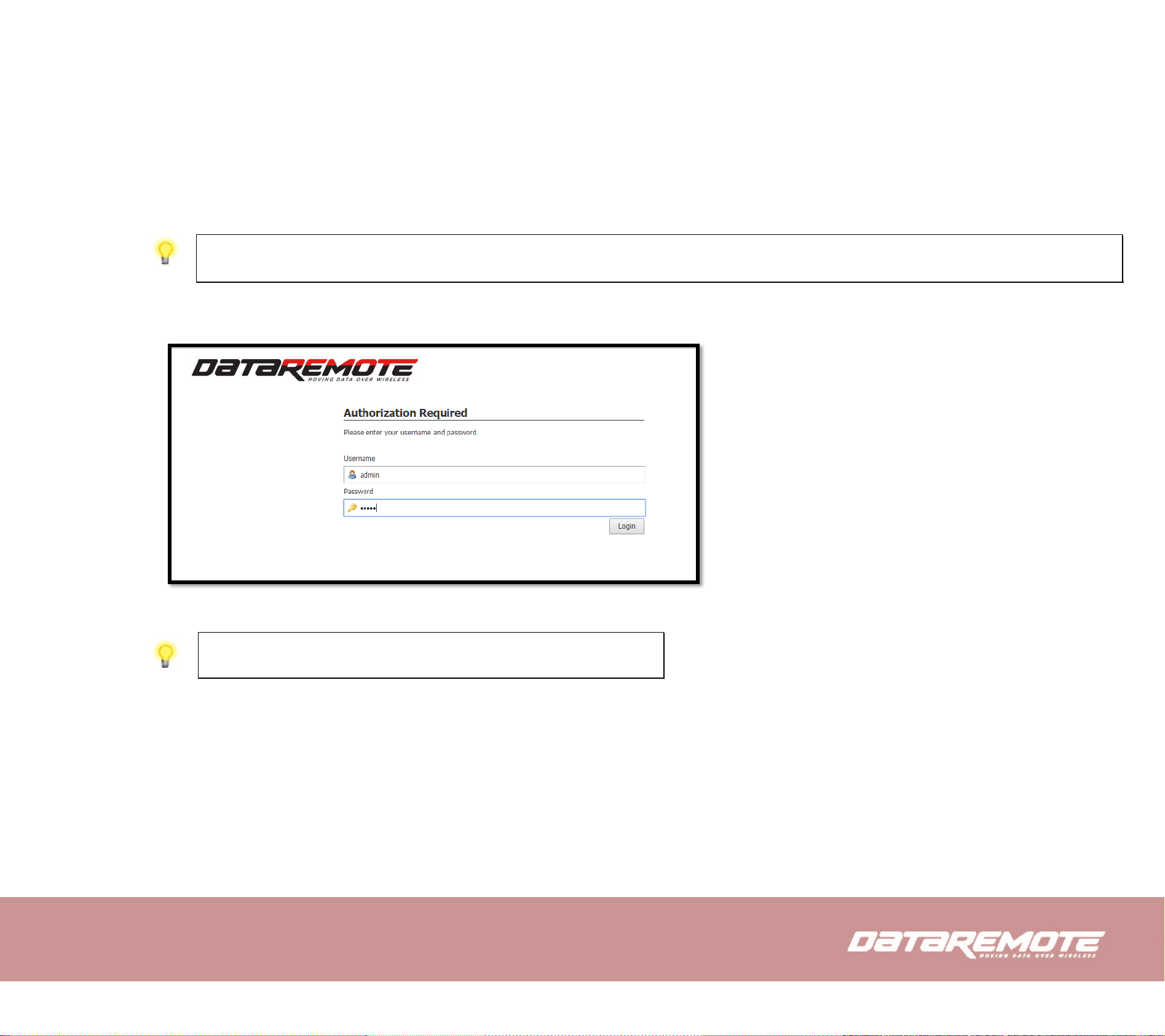
2. Open a web browser on your PC and type http://192.168.1.1. The following window will be open to ask for username and
password, and you can choose language.
3. For administrator mode operation, please type “admin/Password1” on Username/Password and click Login to configuration.
Notice: If you fail to access to the web configuration, please go to “Trouble
Shooting” for detecting and solving your problems.
4. The web page can be logged out after 5 minutes without any operation.
Page 15
4.2.2 From WAN port
1. Make sure your PC can connect to the router’s WAN port correctly.
2. Getting the IP addresses of WAN port using Voice prompt.
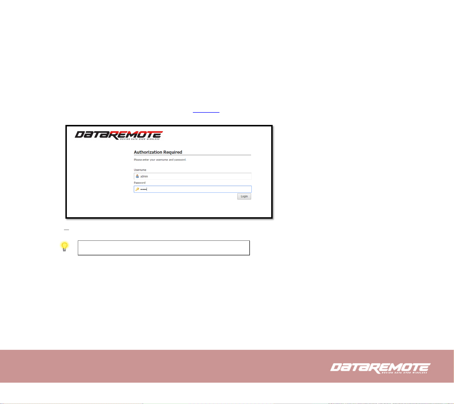
3. Open a web browser on your PC and type http://the IP address of WAN port. The following window will be open to ask for
username and password.
4. For administrator mode operation, please type “admin/Password1” on Username/Password and click Login to configuration.
Notice: If you fail to access to the web configuration, please go to “Trouble
Shooting” for detecting and solving your problem.
5. The web page can be logged out after 5 minutes without any operation.
Page 16
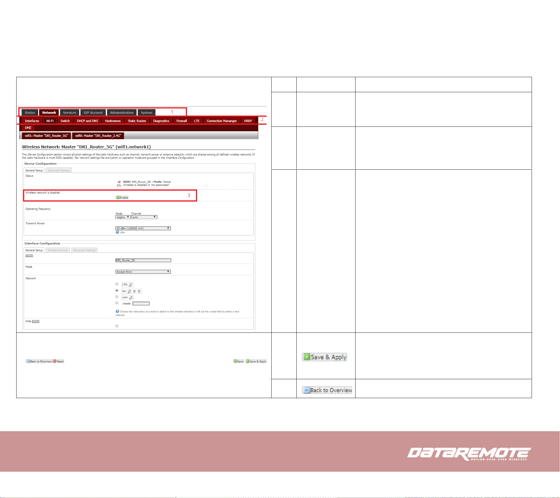
4.3 Webpage
No.
Name
Description
1
Navigation bar
Click navigation bar, many sub-navigation bar will
appear in the place 2
2
Title
Click sub-navigation bar to choose one configuration
page
3
Parameter
To configuration the parameters
• Every time making some changes, user should
press this button to confirm the changes.
• Save button will only save the changes but they
won’t be applied
To return to the original page
Page 17
Reset the changes that have been made
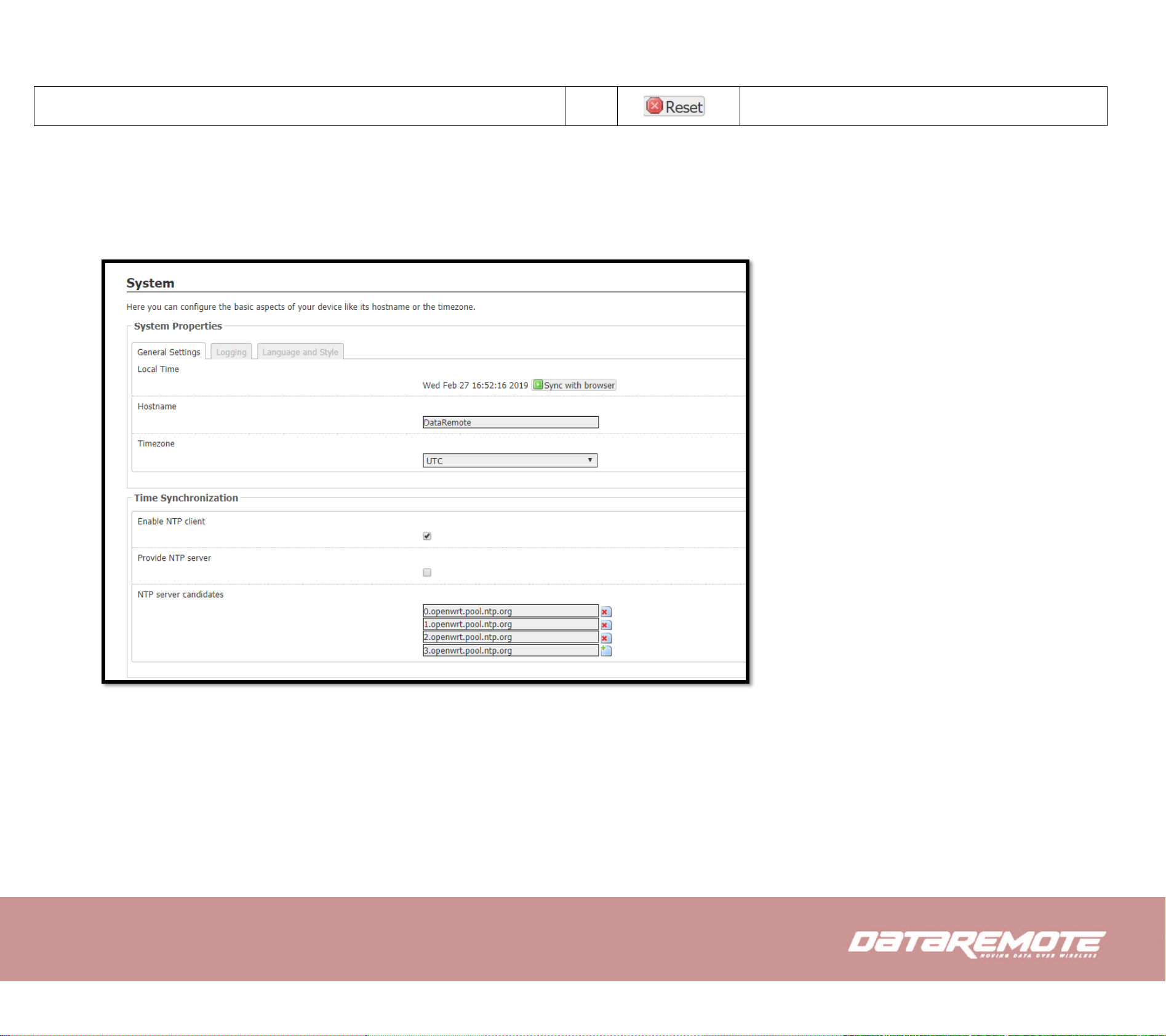
4.4 Setting up the Time Zone
Open System/System webpage as shown below, please select the Time Zone for the router installed and specify the NTP server and set
the update interval in NTP synchronization.
Page 18
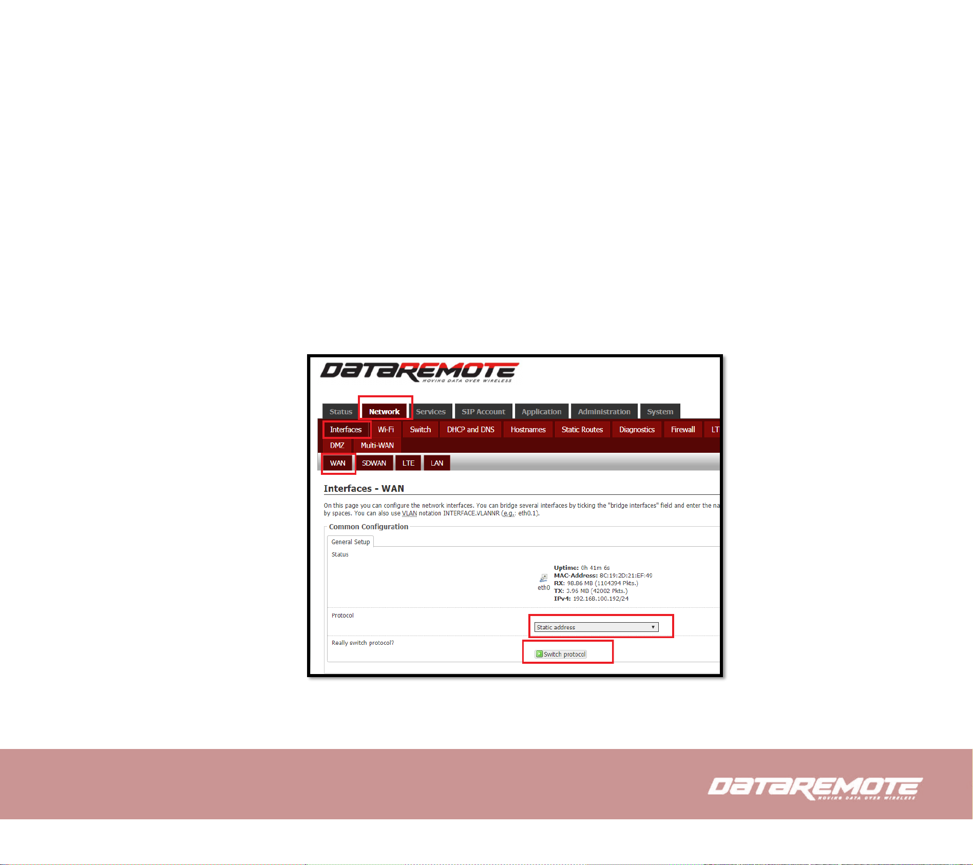
4.5 Setting up the Internet/WAN Connection
Open the Network/Interfaces/WAN webpage as shown below; please select the appropriate IP Mode according to the information from
your ISP. On this page you can configure the network interfaces. You can bridge several interfaces by ticking the "bridge interfaces" field
and enter the names of several network interfaces separated by spaces. You can also use VLAN notation INTERFACE.VLANNR (e.g.:
eth0.1).
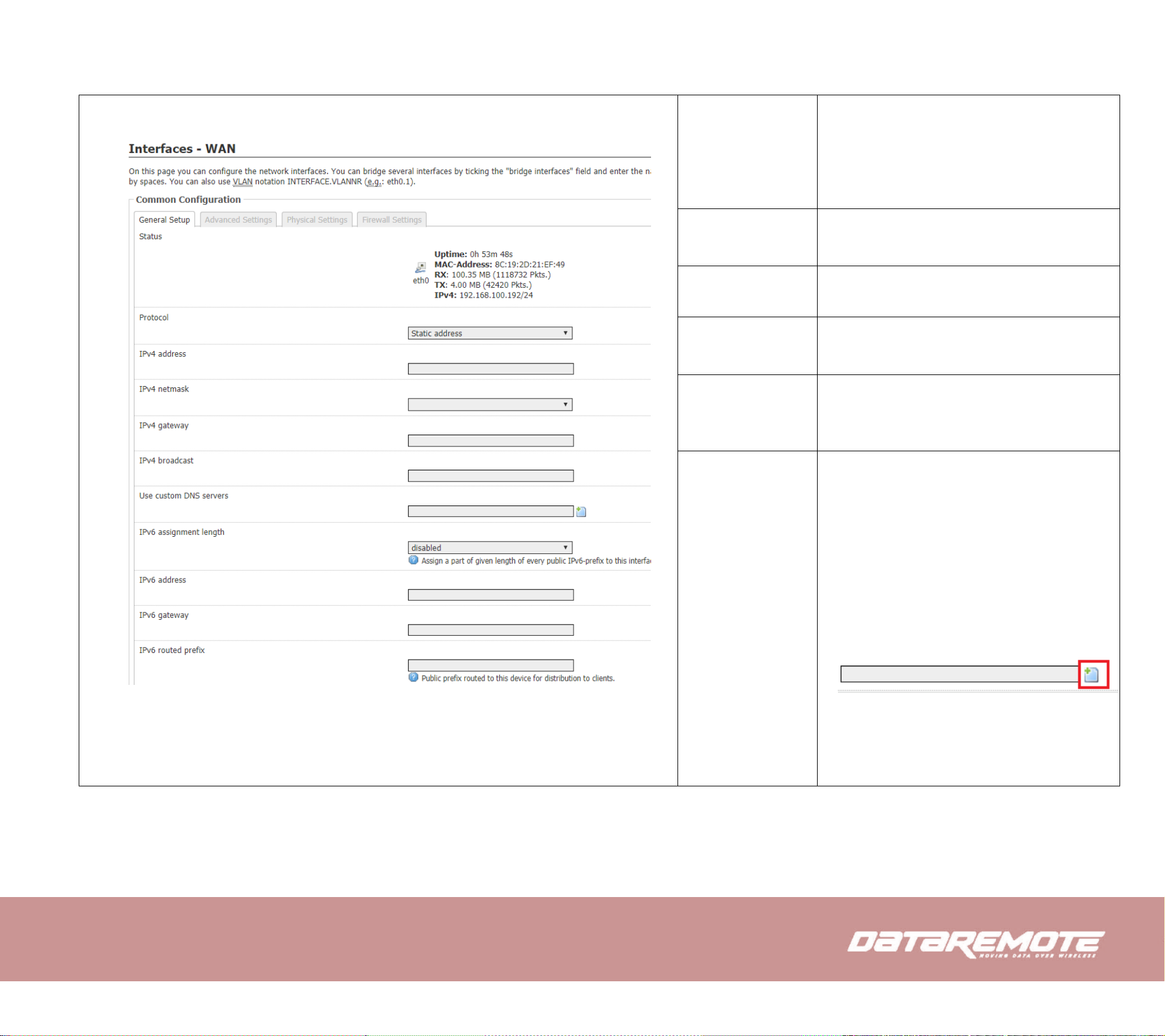
4.5.1 Static IP
You will receive a fixed public IP address or a public subnet, namely multiple public IP addresses from your DSL or Cable ISP service
providers. In most cases, a Cable service provider will offer a fixed public IP, while a DSL service provider will offer a public subnet. If you
have a public subnet, you could assign an IP address to the WAN interface.
Page 19
Protocol
• Use the dropdown menu select the
desired protocol
• Select “Switch Protocol”
IPV4 Netmask
Select the desired Netmask or select custom
to insert your own custom netmask
IPV4 Address
Type the IP address
IPv4 broadcast
Type the broadcast IP
IPV4
Gateway
Type the gateway address for IPV4
Use custom
DNS Server
Type in the Custom DNS IP address for the
route
You can always add another DNS IP address
by selecting :
Page 20
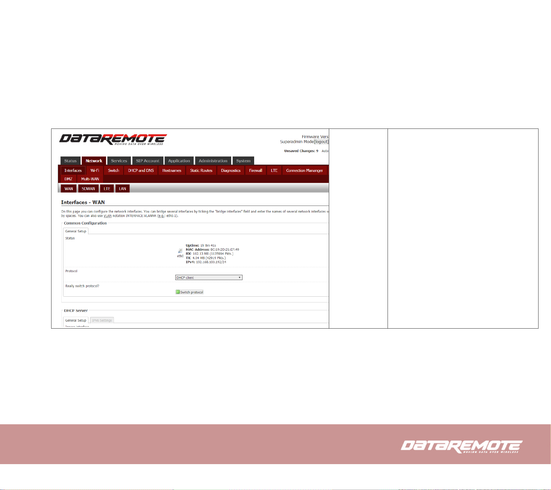
4.5.2 DHCP
It is not necessary for you to type any IP address manually. Simply choose this type and the system will obtain the IP address automatically
from DHCP server.
WAN IP Mode
The mode for obtain IP address
Page 21
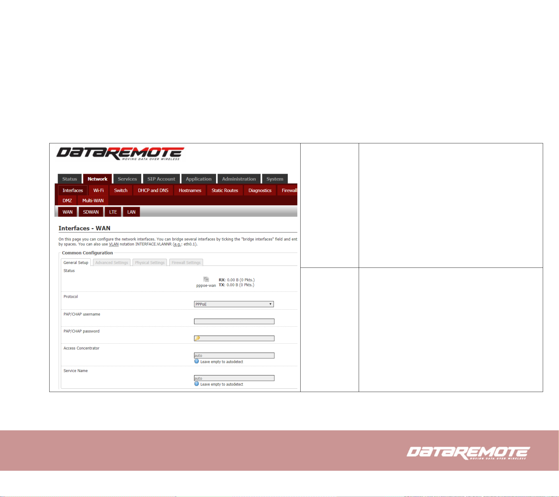
4.5.3 PPPoE
PPPoE stands for Point-to-Point Protocol over Ethernet. It relies on two widely accepted standards: PPP and Ethernet. It connects users
through an Ethernet to the Internet with a common broadband medium, such as a single DSL line, wireless device or cable modem. All the
users over the Ethernet can share a common connection.
PPPoE is used for most of DSL modem users. All local users can share one PPPoE connection for accessing the Internet. Your service
provider will provide you information about user name, password, and authentication mode.
PAP/CHAP
username
Assign a specific valid user name provided by the ISP
PAP/CHAP
password
Assign a valid password provided by the ISP
Page 22
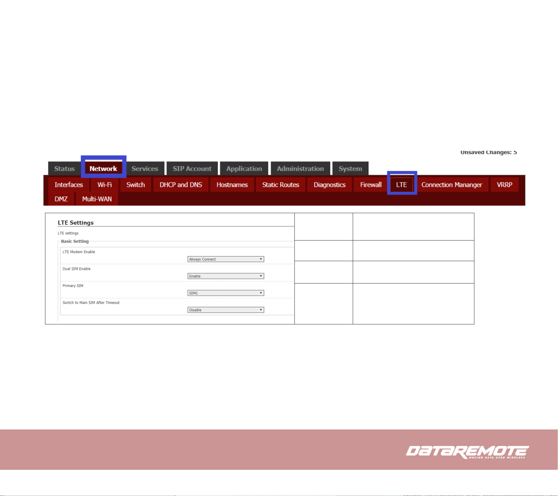
4.6 Setting up the Internet/LTE Connection
4.6.1 LTE
LTE Modem
Enable
Select to Disable, Auto Connect and
Always Connect.
Dual SIM
Enable or Disable Dual SIM
Primary SIM
Set to Primary SIM to SIM1 or SIM2
Switch to
Main SIM
After Timeout
Enable or Disable to switch
Secondary SIM if Primary SIM Fails
Page 23

SIM1 APN
Enter SIM1 APN
SIM1 Dial
Number
Insert SIM1 Dial number
SIM1
Username
Insert SIM1 Username
SIM1
Password
Insert SIM1 Password
SIM2 APN
Enter SIM2 APN
SIM2 Dial
Number
Insert SIM2 Dial number
SIM2
Username
Insert SIM2 Username
SIM2
Password
Insert SIM2 Password
Page 24

When LTE connected successfully, return the Status page, you can check the link status and the IP address obtained from the cellular carrier.
Page 25

4.7 Setting up the Wireless Connection
4.7.1 Enable Wireless and Setting SSID
Open 2.4G (5G) /Basic webpage as shown below
Select to enable
Page 26

Operating
Frequency
Transmit Power
Select Mode & Channel
Select Transmit power
Mode
Select to AP , Client. WiFi , AD-HOC,
Access point(WDS), Client(WDS) ,
Static(WDS)
Network
Select the check box for desired
network.
Select the
Wireless
Security Tab to
select desired
Wireless
Security
Select Desired Security(WEP Open
System , WEP Shared Key, WPAPSK, WPA2-PSK, WPAPSK/WPA2-MSK Mixed Mode)
Page 27

Mode
Select to AP , Client. WiFi , AD-HOC,
Access point(WDS), Client(WDS) ,
Static(WDS)
Network
Select the check box for desired
network.
Select the
Wireless
Security Tab to
select desired
Wireless
Security
Select Desired Security(WEP Open
System , WEP Shared Key, WPAPSK, WPA2-PSK, WPAPSK/WPA2-MSK Mixed Mode)
Page 28

4.7.2 Encryption
Open 2.4G (5G)/Security webpage to set the encryption of routers.
WEP Open System , WEP Shared Key, WPA-PSK, WPA2-PSK, WPA-PSK/WPA2-MSK
Mixed Mode
Open WPA-PSK
OPEN WEP
Cipher
Select Cipher and choose desired option
Key
Enter desired Password
WEP Keys
Set the WEP key. Select 64-bit key to
enter Hex is 10 characters, or ASCII
code is 5characters; select 128-bit
keys need to enter Hex is 26
characters, or ASCII is 13characters.
Page 29

4.8 Setting up WAN Failover
4.8.1 WAN Failover List
WAN Failover works in multiple outbound links to assure that you maintain Internet connectivity if a loss of connectivity occurs on one of
your WAN connections. If one of your ISP links goes down, WAN Failover will automatically route all traffic over the other WAN(s) until
service is restored.
CDS-9090 allows failover of the default route to WAN
interfaces. This part of settings allows ranking each WAN
interface in order of preferred usage for the default route.
The default route will always be set to the highest-priority
connected WAN interface. The assignment changes as
WAN interfaces connect or disconnect from the current
network.
Default Route Selection support WAN/ WiFi 2.4G/ LTE
and WiFi 5.0G. WAN Failover list switch over from
Number1 (highest priority) to Number 4 (lowest priority).
Page 30

4.8.2 Connection Manager
Enable
Enable this function, WAN Failover is
based on ping result. Disable this
function, WAN Failover is based on
each interface physical status.
Detect
Interval
Interval time for detecting WAN
connection.
Ping this IP
The IP address for ping detection
Max Try
Times for
Ping
Setup the re-try times for ping
Page 31

4.9 Register
4.9.1 Get the Accounts
CDS-9090 has eight RJ-11 phone ports, you can use it to make SIP call, and before registering, you should get the SIP account from you
administrator or provider.
4.9.2 Connections
Connect CDS-9090 to the Internet properly
4.9.3 Configuration SIP from Webpage
Step 1.Open SIP Account/Line 1 webpage, as the picture in the right side.
Step 2. Fill account which get from you administrator into Display Name parameter, Phone Number parameter, and Account parameter.
Step 3.Fill password which get from you administrator into Password parameter.
Step 4.Press button in the bottom of the webpage to save changes.
Note: if there is Please REBOOT to make the changes effective! please press Reboot button to make changes effective.
Page 32

4.9.4 View the Register Status
To view the status, please open Status webpage and view the value of register status. The value is registered like the following picture which
means CDS-9090 have registered normally and you can make calls.
Page 33

4.10 Make Call
4.10.1 Calling phone or extension numbers
To make a phone or extension number call:
a) Both ATA and the other VoIP device (i.e., another ATA or other SIP products) have public IP addresses, or
b) Both ATA and the other VoIP device (i.e., another ATA or other SIP products) are on the same LAN using private or public IP addresses, or
c) Both ATA and the other VoIP device (i.e., another ATA or other SIP products) can be connected through a router using public or private IP
addresses.
To make a call, first pick up the analog phone or turn on the speakerphone on the analog phone, input the IP address directly, end with #.
4.10.2 Direct IP calls
Direct IP calling allows two phones, that is, an ATA with an analog phone and another VoIP Device, to talk to each other without a SIP proxy. VoIP
calls can be made between two phones if:
a) Both ATA and the other VoIP device (i.e., another ATA or other SIP products) have public IP addresses, or
b) Both ATA and the other VoIP device (i.e., another ATA or other SIP products) are on the same LAN using private or public IP addresses, or
c) Both ATA and the other VoIP device (i.e., another ATA or other SIP products) can be connected through a router using public or private IP
addresses.
To make a direct IP call, first pick up the analog phone or turn on the speakerphone on the analog phone, Input the IP address directly, with the end
“#”.
Page 34

5 Web Configuration
When login successfully, the
webpage shows the basic
information about the router, such
as the current WAN IP, DNS server
IP, WAN port connection mode,
WAN link status, wireless SSID,
wireless channel and F/W version
This chapter will guide users to execute full configuration through admin mode operation.
5.1 Login
Step 1.Connect the LAN port of the router to your PC
Step 2.Open a web browser on your PC and type in http://192.168.1.1. The window will ask for typing username and password. And you
can choose language, too.
Step 3.Please type “admin/Password1” on Username/Password for administration operation. Now, the Main Screen will appear like below.
Page 35

5.2 Status
This webpage shows the status information about
product information, Network and system.
It shows the basic information of the product, such
as product name, serial number, MAC address,
hardware version and software version.
It also shows the information of Link Status, WAN Port
Status, memory and LAN Port Status.
And it shows the current time and the running time of
the product.
The picture in the right side is the CDS-9090’s Status
webpage.
Page 36

5.3 Network
You can configuration the LAN port, DDNS, Multi WAN,DMZ, MAC Clone, Port Forward and so on in these two bars.
5.3.1 LAN
LAN Port:
The most generic function of router is NAT. What NAT does is to translate the packets from public IP address to local IP address to forward the right
packets to the right host and vice versa.
IPV4 address
Type in local IP address for connecting
to a local private network
IPV4 Subnet Mask
Type in an address code that
determines the size of the network.
DNS Mode
Set the DNS Mode from Auto and
Manual.
Use custom DNS
Servers
Input DNS IP address, you can also
add more DNS IP address by selecting
IPV4 broadcast
Input broadcast IP.
Page 37

5.3.2 VPN/L2TP
VPDN
VPN Enable
Enable PPTP or L2TP VPN Client
Initial Service IP
VPN server IP address
User Name
The account for authentication
Password
The password for authentication
VPN As Default Route
The remote virtual IP as default
gateway .
MPPE Stateful(PPTP
Only)
Stateless encryption provides a lower
level of performance, but will be more
reliable in a lossy network
environment.
Require MPPE(PPTP
Only)
enable MPPE (Microsoft Point-to-
Point Encryption). It’s a protocol for
encrypting data across PPP and VPN
links.
L2TP Tunnel Name
Enter L2TP Tunnel Name.
L2TP Tunnel Password
Enter L2TP tunnel password in this
item.
Page 38

L2TP Server
L2TP Server Enable
Select to enable L2TP server.
Local IP Address
Set the IP address of L2TP server.
Pool Start Address
Set the IP pool start IP address which
will assign to the L2TP clients.
Pool End Address
Set the IP pool end IP address which
will assign to the L2TP clients.
Max MTU
Maximum Transmission Unit. It is the
identifier of the maximum size of
packet, which is possible to transfer in
a given environment.
Max MRU
Maximum Receiving Unit. It is the
identifier of the maximum size of
packet, which is possible to receive in
a given environment.
User Name
Set the username which will assign to
L2TP client.
Password
Set the password which will assign to
L2TP client.
Page 39

IPsec Connection
IPSec Connection List
The connection status of IPSec VPN
IPSec Connection
Select the specify VPN
Connection Name
The name of this IPSec VPN
IPSec Enable
Select to enable or disable IPSec VPN
Interface
Select the interface for encryption
IPSec Networking Type
The connection type of networking
Authentication Type
The authentication method of IPSec
VPN
PSK
The secret of IPSec VPN
Local ID Type
Select the local ID type for IKE
negotiation
Local WANs IP
Address/FQDN
Local IP address or domain name for
IKE negotiation
Remote ID Type
Select the remote ID type for IKE
negotiation
Page 40

Remote WANs IP
Address/FQDN
the address of remote side IPSec VPN
server
Local LAN IP Address/
Subnet Mask Length
IPSec local protected subnet’s address.
Remote LAN IP
Address/ Subnet Mask
Length
IPSec remote protected subnet’s
address.
Policy Protocol
The policy protocol for encryption
Encapsulated Mode
Select the security protocols
NAT Enable
Enable NAT Traversal for IPSec. This
item must be enabled when router
under NAT environment.
Mode
Select from “Main” and “aggressive”
for the IKE negotiation mode in phase
1.
Encryption Algorithm
Select Encryption Algorithm to be
used in IKE negotiation.
Integrity Algorithm
Select Integrity Algorithm to be used
in IKE negotiation.
Diffie-Hellman (DH)
Group
Select Diffie-Hellman Group to be
used in key negotiation phase 1.
SA Lifetime of Phase 1
Set the lifetime in IKE negotiation.
DPD Time Interval(s)
Set the interval after which DPD is
triggered if no IPSec protected packets
is received from the peer.
DPD Timeout(s)
Set the timeout of DPD packets.
Page 41

Encryption Algorithm
Select Encryption Algorithm to be
used in IPSec SA negotiation.
Integrity Algorithm
Select Integrity Algorithm to be used
in IPSec SA negotiation.
SA Lifetime of Phase 2
Set the lifetime in IPSec SA
negotiation
PFS
Enable or disable PFS. (Perfect
Forward Secrecy)PFS will ensure the
same key will not be generated again
5.3.3 DMZ/Port Forward
DMZ
DMZ Enable
If or not enable DMZ.
DMZ Host IP Address
Enter the private IP address of the
DMZ host
Page 42

Port Forward
Port Forwarding
Comment
Assign a meaningful name for port
forwarding.
IP Address
The IP address in LAN side
Port Range
The port range for LAN host, from 1 to
65535
Protocol
Select from “TCP”, “UDP” or
“TCP&UDP”
Virtual Servers
Comment
Assign a meaningful name to the
virtual server.
IP Address
The IP address of the system on your
internal network that will provide the
virtual service.
Public Port
The port that will be accessed from the
Internet.
Private Port
The port that will be used on your
internal network.
Protocol
Select from “TCP”, “UDP” or
“TCP&UDP”
Friendly IP
The IP address allow to access from
WAN side.
IP Address
The IP address of friendly IP
Page 43

5.3.4 DDNS
Dynamic DNS Provider
Select the DDNS service which you
have established an account with.
Account
Enter account that DDNS server
provided.
Password
Enter password that DDNS server
provided.
DDNS URL
Enter the DDNS Domain name or IP
address.
Status
Show current status of DDNS
5.3.5 QoS
QoS Enable
Select to enable QoS function
Upstream
Prescribe uplink speed of router.
Downstream
Prescribe downlink speed of router.
Name
Set server name of the service that you
want to set it with QoS Control.
Source IP Address
Enter source IP address of the user (for
example, PC) who you want to set it
with QoS Control.
Dest IP Address
Enter destination IP address of the user
(for example, PC) who you want to set
Page 44

it with QoS Control.
Protocol
Select from TCP /UDP /ICMP
Src.Port Range
Source port range of the service that
you want to set it with QoS Control.
Dst.Port Range
Destination port number of the service
that you want to set it with QoS
Control.
Physical Port
Select from WAN/LAN
DSCP
set the Differentiated Services Code
Point (DSCP) values in Quality of
Service (QoS)
802.1p
802.1p is an IEEE standard that
describes mechanisms to prioritize
traffic and perform dynamic multicast
filtering.
VLAN ID
When configuring a VLAN tag-based
QoS policy map, the router applies the
policy to one Ethernet port and only to
the VLANs on that particular port.
Remark DSCP
Remark DSCP Tag
Remark 802.1p
Remark 802.1p Tag
Remark VLAN_ID
Remark VLAN_ID Tag
Priority
Select from voice (VO), video (VI),
best effort (BE), and background (BK)
Drop
Select to Drop or not drop the packet
Page 45

Rate Limit
Limit the speed of this rule
5.3.6 MAC Clone
Some ISPs will require you to register your MAC address. If you do not wish to re-register your MAC address, you can have the router clone the
MAC address that is registered with your ISP. To use the Clone Address button, the computer viewing the Web-based utility screen will have the
MAC address automatically entered in the Clone WAN MAC field.
MAC Address Clone
Select to enable or disable
MAC Address
The MAC address for clone
Get Current PC MAC
clone the currently PC MAC address
to router’s Internet port automatically
Page 46

5.3.7 Routing
Destination
The IP address of packets that will take
this route.
Host/Net
Select the Host or Networking
Gateway
Specifies the next hop to be taken if
this route is used.
Interface
Specifies the interface LAN/
INTERNET/ VOICE/ TR069/ VPN
Comment
Set comment of this routing.
Page 47

5.3.8 WPS
WPS (Wi-Fi Protected Setup) provides easy procedure to make network connection between wireless station and wireless access point (vigor
router) with the encryption of WPA and WPA2.
It is the simplest way to build connection between wireless network clients and vigor router. Users do not need to select any encryption mode and
type any long encryption passphrase to setup a wireless client every time. He/she only needs to press a button on wireless client, and WPS will
connect for client and router automatically. Press button less than 5s for 2.4GHz, press button between 5 to 10s for 5.0GHz.
WPS Config
If or not enable WPS.
WPS Summary
The status for Current connection,
SSID and so on
WPS Progress
PIN: In the following PIN options, fill
in the PIN code of the client (wireless
card, etc.) that needs to be accessed,
and then click Apply.
PBC: PBC mode There are two ways
to start, you can directly press the PBC
button on the hardware, or select to
PBC mode, and then click Apply.
WPS Status
There are three WPS states:
WSC: Idle state is idle
WSC: Start WSC Process Status is to
start sending messages
WSC: Success: If a client accesses an
AP, the WPS connection succeeds
Page 48

5.3.9 Station list
You could monitor stations which
associated to this AP here.
5.3.10 Client
Enable WiFi Client would be one option for WAN Failover, select as the default route.
Connection Status
Current WiFi Client connect status
Connect
Select one SSID and press the button,
enter the password for the SSID.
Refresh
Refresh the SSID scan result
Add
Add one new/hidden SSID manually
Page 49

Page 50

5.4 Phone
5.4.1 VoIP QoS
SIP QoS(0-63)
QoS services can improve the quality of
voice applications. The default value is
46, and the range of values can be set
from 0 to 63.
RTP QoS(0-63)
Once Multi-WAN port is enabled, select
the corresponding voice PPPoE server
VID, the devices under the same VLAN
can transmit voice data.
5.4.2 Dial Plan
Dial Plan
Select to enable or disable
Unmatched Policy
Select from Accept or Reject
FXS
Select the FXS port
Digital Map
Fill in the expression of digital map,
please refer to the digital map syntax.
Action
Select the match action of the digital map,
Deny means the device will reject the
matching number dialing, and Dial Out
means the device can dial out the
matching number
Page 51

5.4.3 Blacklist
You can upload or download the phone
book, blacklist.
5.4.4 Call Log
On this page, users can view replay lists
(outgoing calls), received calls, and missed
calls.
Page 52

5.5 SIP Account
5.5.1 FXS1/2/3/4/5/6/7/8 SIP Account
Line Enable
Select to enable or disable Line
Outgoing Call without
Registration
Select to enable or disable this function
Display Name
The display name of this SIP number
Phone Number
The phone number provided by SIP
server
Account
The account provided by SIP server for
authentication
Password
The password provided by SIP server for
authentication
5.5.2 FXS1/2/3/4/5/6/7/8 Audio Configuration
Audio Codec Type
Select the appropriate encoding
G.723 Coding Speed
Select from 5.3kbps or 6.3kbps
Packet Cycle(ms)
Set the RTP packetization period. The
default configuration is 20ms
Silence Supp
Mute enable
Page 53

Echo Cancel
Echo Cancellation is enabled by default
Auto Gain Control
Used to automatically adjust the speech
level of an audio signal to a
predetermined value.
Use First Matching
Vocoder in 200OK SDP
Select to enable or disable
Codec Priority
Select from local or remote
Packet Cycle Follows
Remote SDP
Select to enable or disable
FAX Mode
Select from T.30/ T.38/ ByPass
ByPass Attribute Value
Select from fax/modem or X-fax/Xmodem
gpmd attribute Enable
Select to enable or disable
T.38 Redundancy
Select to enable or disable
Max Fax Rate
Select from 14400/ 9600/ 4800
Page 54

5.5.3 FXS1/2/3/4/5/6/7/8 Supplementary Service Subscription
Call Waiting
Select to enable or disable
Hot Line
Fill in the hotline number. After the
subscriber is set up successfully, the
hotline number will be automatically
dialed immediately after off-hook
MWI Enable
Enable WMI (Message Waiting
Indication), enable this function if you
want to use voicemail
Voice Mailbox Numbers
Fill in the voicemail code provided by
your ISP
MWI Subscribe Enable
Select to enable or disable
VMWI Serv
Select to enable or disable
DND
After enabling this option, any phone call
can not be dialed in, default is disable.
Speed Dial
Pre-set the phone number for Fast call
Page 55

5.6 Security
5.6.1 Filtering Setting
Filtering
Select to enable or disable
Default Policy
Select from Drop or Accpet
Interface
Select from LAN or WAN
Mac address
Fill MAC address for Filtering control
Dest IP Address
Fill Destination IP address for Filtering
control
Source IP Address
Fill source IP address for Filtering control
Protocol
Select from TCP/ UDP /ICMP
Dest. Port Range
Fill Destination port range for Filtering
control
Src Port Range
Fill source port range for Filtering control
Action
Select from Accept or Drop
Comment
Fill the comment for this filtering rule
Page 56

5.6.2 Content Filtering
Filtering
Select to enable or disable
Default Policy
Select from Drop or Accpet
Local File
Select the local file for upload
Current Webs URL
Filters
Existing URL filtering rules (blacklist)
Add a URL Filter
Add a URL filtering rule
URL
Fill the URL for webs filtering
Current Website Host
Filters
Existing keywords (blacklist)
Add a Host(keyword)
Filter
Add a keyword rule
Keyword
Fill the keyword for filtering
Page 57

Page 58

5.7 Application
5.7.1 Advance Nat
In this page, you can choose to enable /
disable FTP, SIP, H323, PPTP, L2TP,
IPSec services.
Page 59

5.7.2 UPnP
UPnP (Universal Plug and Play) supports
null-setting for networking, can
automatically find a variety of networked
devices. When UPnP is enabled, UPnPenabled devices are allowed to
dynamically access the network, obtain IP
addresses, and transmit performance
information. If you have DHCP and DNS
servers on your network, you can
automatically obtain DHCP and DNS
services. UPnP-enabled devices can be
automatically disconnected from the
network without affecting the device or
other devices on the network.
Page 60

5.7.3 IGMP
Multicast has the function of sending the
same data to multiple devices. An IP host
uses the IGMP (Internet Group
Management Protocol ) to report
multicast group memberships to send data
to neighboring routers, and the multicast
router uses IGMP to discover which hosts
belong to the same multicast group.
5.8 Administration
Note – The number of FXS ports and available parameters may vary depending on the device model.
5.8.1 Management
Save Config File
Local File
Select the local file for configuration
Upload
Use this option to restore previously
saved router configuration settings.
Download
This option allows you to export and then
save the router's configuration to a file on
your computer. Be sure to save the
configuration before performing a
Page 61

firmware upgrade.
Administrator Settings
New User Name
New user name for management
New Password
Type the password for user
Confirm Password
Type the same password again
Language
Setup the language for operation,
select from English or Spanish
Refresh Interval
The auto refresh interval for LTE
status
Management using VPN
Select to enable or disable
Remote Web Login
Allow host remote access from Active
WAN
Local Web Port
Enter the HTTP port number for
accessing from local side
Web Port
Enter the HTTP port number for
accessing from remote side
Web Idle Timeout(0 -
60min)
Timeout for web idle activity
Allowed Remote
IP(IP1;IP2;...)
Allow the host with specified IP
address to access from webpage.
Page 62

Time/Date Settings
NTP Enable
Select this option if you want to
synchronize the router's clock to a
Network Time Server over the
Internet.
Option 42
Obtain NTP Server via DHCP Server
Current Time
Displays the time currently maintained
by the router.
Sync with host
Synchronize with your current host's
system time
NTP Settings
Select your local time zone from pull
down menu.
Primary NTP Server
Type the primary Network Time
Server for synchronization.
Secondary NTP Server
Type the secondary Network Time
Server for synchronization.
NTP synchronization(1 -
1440min)
Interval time for NTP synchronization.
Reset to Factory Default
This option restores all configuration
settings back to the settings that were in
effect at the time the router was shipped
from the factory. Any settings that have
not been saved will be lost.
Page 63

5.8.2 Firmware Upgrade
Once you have a firmware update on your
computer, use this option to browse for
the file and then upload the information
into the router.
5.8.3 Scheduled Tasks
Scheduled WiFi Enable
Select to enable or disable
SSID
Choose the specified SSID for
scheduled WiFi
Scheduled Mode
Select the Schedule mode for cycle time
WiFi Work Time
Setup the working time for WiFi
broadcast
Schedule dReboot
Select to enable or disable
Scheduled Mode
Select the Schedule mode for cycle time
Time
Setup the reboot timing
Scheduled PPPOE
Select to enable or disable
Page 64

Scheduled Mode
Select the Schedule mode for cycle time
Time
Setup the PPPoE connection timing
Page 65

5.8.4 Provision
Please refer to the provision user manual to test provision.
Provision Enable
Select to enable or disable
Resync On Reset
Enable or disable DIV378 Resync after
rebooting
Resync Random
Delay(sec)
Setup the maximum delay for request
synchronization
Resync Periodic(sec)
If the last resynchronization is
unsuccessful, after the "Rsync Retry
Delay Error" time, after "time, the
device will retry the resynchronization
Resync Error Retry
Delay(sec)
Set the timed resynchronization
Forced Resync
Delay(sec)
If it is time to re-sync, but the device is
busy, in this case, the device will wait
for some time, the longest is "forced
resynchronization delay", the default is
14400s, time after the device will be
forced to re-sync.
Resync After Upgrade
After the resynchronization, enable or
disable the firmware update function
Resync From SIP
Select to enable or disable resync from
SIP
Option 66
Specifies the TFTP (Simple File
Transfer Protocol) server address
Page 66

Option 67
Specifies the startup file name
Config File Name
Configure the file name
User Agent
The name of user agent
Profile Rule
The URL of the configuration file
Note that the specified file path is
relative to the root directory of the
TFTP server
Upgrade Enable
Select to enable or disable
Upgrade Error Retry
Delay(sec)
Interval time for retry upgrade firmware
if error happen
Upgrade Rule
The path of firmware located
5.8.5 TR069 – Device Management
TR069 Enable
Select to enable or disable
CWMP
Select to enable or disable
ACS URL
The URL of ACS agent
User Name
The user name of ACS agent
Password
The password of ACS agent
Periodic Inform Enable
Select to enable or disable the periodic
notification function is
Periodic Inform Interval
Setup periodic Notification Interval
Page 67

User Name
User name for TR069 server connected
to DUT
Password
Password for TR069 server connected to
DUT
5.9 System Log
If you enable the system log in Status/syslog webpage, you can view the system log in this webpage.
Page 68

Page 69

5.9.1 Logout
Press the logout button to logout, and then the login window will appear.
5.9.2 Reboot
Press the Reboot button to reboot CDS-9090.
Page 70

6 Trouble shooting of the guide
6.1 Setting your PC gets IP automatically
Following are the process of setting your PC gets IP automatically
Step 1.Click the “begin”
Step 2.Select “control panel”, then double click “network connections” in the “control panel”
Step 3. Right clicks the “network connection” that your PC uses, select “attribute” and you can see the interface as picture 1:
Step 4.Select “Internet Protocol (TCP/IP)”, click “attribute” button, and you can see the interface as following Picture 2 and you should click the “Get IP address automatically”.
Picture 1
Picture 2
Page 71

6.2 Cannot connect to the configuration Website
Solution:
Check if the Ethernet cable is properly connected, then
Check if the URL is right wrote, the format of URL is: http:// the IP address: 8080, 8080 must be added, then
Check if the version of IE is IE8, or use other browser such as Firefox or Mozilla, then Contact your administrator, supplier, or ITSP for more information or assistance.
6.3 Password reset(Forgot Password)
If user changed the password and then forgot, you can not access to the configuration website.
Solution:
To factory default: press reset button 10s.
Page 72

7 Statement
FCC Radiation Exposure Statement
DataRemote Incorporated. Declares that this device is in compliance with the essential requirements and other relevant provisions of Directive
1999/5/EC. This equipment has been tested and found to comply with the limits for a Class B digital device, pursuant to part 15 of the FCC ru les. These limits
are designed to provide reasonable protection against harmful interference in a residential installation. This equipment generates, uses and can radiate radio
frequency energy and, if not installed and used in accordance with the instructions, many cause harmful interference to radio communications. However, there
is no guarantee that interference will not occur in a particular installation. If this equipment does cause harmful interference to radio or television reception, which
can be determined by turning the equipment off and on, the user is encouraged to try to correct the interference by one or more of the following measures:
• Reorient or relocate the receiving antenna.
• Increase the separation between the equipment and receiver.
• Connect the equipment into an outlet on a circuit different from that to which the receiver is
connected.
• Consult the dealer or an experienced radio/TV technician for help.
To assure continued compliance, any changes or modifications not expressly approved by the party
responsible for compliance could void the user’s authority to operate this equipment. (Example- use
only shielded interface cables when connecting to computer or peripheral devices)
FCC Radiation Exposure Statement
This equipment complies with FCC RF radiation exposure limits set forth for an uncontrolled
environment. This transmitter must not be co-located or operating in conjunction with any other
Page 73

antenna or transmitter.
This equipment complies with Part 15 of the FCC Rules. Operation is subject to the following two
conditions:
(1) This device may not cause harmful interference, and
(2) This device must accept any interference received, including interference that may cause
undesired operation.
This equipment should be installed and operated with minimum distance 20cm between the
radiator and your body.
Operations in the 5.15-5.25GHz band are restricted to indoor usage only.
 Loading...