

Page 1
Installation And Operation
BASIC A/B SWITCHES
K-AB-D25 K-AB-M34
SCOPE OF THIS DOCUMENT
This document covers the following models:
K-AB-D25 K-AB-D25-R
K-AB-M34 K-AB-M34-R
For the purposes of clarity, all above models are referred to as "K-AB ".
Card Nest
K-AB-R-12 Universal 12 position card nest for all K-AB cards above and all other K-AB cards.
GENERAL DESCRIPTION
Dataprobe's Relay Controlled A/B Switches, (K-AB) permits automatic, remote or manual switching of a
Common line between two circuits, A or B. Multiple relays are used to switch the following circuit types:
D25: 25 Pin D Subminiature Connectors; 23 Leads Switched,
Pins 1 (FG) and Pins 7 (SG) Unswitched
M34: 34 Pin ‘M’ (V.35) Connectors. 19 Leads Switched,
Pins A (FG) and Pins B (SG) Unswitched
When the relays are in the relaxed position, the Common Port is connected to Port A (Position A).
When a selected external control signals is supplied, the relays are energized and the Common Port is
connected to Port B (Position B). The K-AB returns to the A Position when the de-energize conditions
are met.
REF: M\MANUALS\K1\KAB-D25-M34_V970905E.DOC
Technical Support Hotline: (201) 967-8788
11 Park Place / Paramus, New Jersey 07652
TEL: 201-967-9300 FAX: 201-967-9090
Website: www. dataprobe.com Email: tech@dataprobe.com
Page 2
Model K-AB-D25 / M34 Page 2
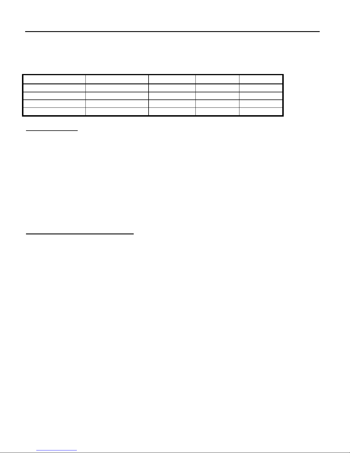
INPUT SELECTION
The K-AB is designed to be operated by an externally supplied control signal. The following control
signals can be used to operate the K-AB. Install the jumpers as shown to configure the K-AB.
Control Lead Logic Required Jumper E1 Jumper E2 Jumper E3
Contact Close=B Open=A Out Contact LO
RS-232 Low=B High=A Out EIA/TTL LO
RS-232 High=B Low=A Out EIA/TTL HI
TTL Low=B High=A In EIA/TTL LO
Gang Switching
An additional setting enables the K-AB card to be used in a multi-circuit gang (simultaneous) switching
arrangement. When used in this manner, one master card controls one or more slave cards. Jumper
E4 sets the master or slave nature of the card.
No Jumper = Independent Use any Control Input, as above
Master = Card Is Master Use any Control Input, as above
Slave = Card Is Slave Set for Contact Closure
Only one card in each card nest can be set as Master.
INSTALLATION AND CONFIGURATION
Connect External Control Source
Standalone models use a nine pin D Subminiature female connector to access the externally supplied
signals. Dataprobe supplies a mating connector kit to assist in fabrication of the proper control cable.
Rack Mounted cards have Control leads terminate on 50 pin Telco connectors on the rear of the
K-AB-R-12 nest. See Appendix A for 9 Pin and Telco Connector Pinouts.
The K-AB is often used in conjunction with other Dataprobe remote switch controlling equipment:
Smart-Line: Multi-Switch Control via Tone dial telephone.
Call Director: Dial Line Sharing device with Switch Control capabilities.
Code Activated Switch: Multi-Switch Control with ASCII Commands.
Dataprobe can supply interconnect cables for any application
Page 3

Model K-AB-D25 / M34 Page 3
MANUAL CONTROL
A front panel three position switch allows Automatic or Manual Control. In the AUTO position, the K-AB
switches on the selected Control Signal. In the Manual A or B Position, these controls are locked out
and the relays assume the selected position.
Status Indication
Two front panel LED's indicate switch status. Remote alarms or displays can be controlled by the K-AB
status signals, form C relay contacts. Status contacts are connected on the 9 pin (standalone) or 50 pin
(rack) connectors. See Appendix A for connector pin assignments.
SPECIFICATIONS
D25 Interface Three 25 Pin D Subminiature, Female Connectors.
23 leads switched. Pins 1 and 7 are Common
M34 Interface 34 Pin ‘M’ type Winchester Connectors
19 leads switched: C,D,E,F,H,J,K,L,P,R,S.T,U,V,W,X,Y,AA,BB.
Pins A and B are Common.
Indicators Two Red LEDs indicate Switch status A or B.
LED's are driven by extra relay contacts.
Stand Alone Enclosure Height....2.75" Width.....8.00"
Depth.....6.25" Weight....1.20 lbs.
Power Source; UL Approved Wall Mounted Power
Supply. 115 VAC 60 Hz
External Control and Status Interface;
9 pin D Subminiature, Female
Rack Mounted Standard 19" equipment Cabinet Mount, 8.75" high.
Card Nest Model K-AB-R-12 Accepts up to 12 cards per nest.
Includes power supply for 115 VAC 60Hz.
External Relay Controls and Status Contacts
Via Two 50 Pin Telco Connectors, Female
Control Circuits EIA RS-232/V.35, External:
Standard EIA RS-232C
Maximum Input + 30 VDC
TTL, External:
Maximum Input +5.5 VDC
Status Signals Contacts Form C, 1A @ 30 VDC. Not protected,
Use proper external suppression.
Page 4

Model K-AB-D25 / M34 Page 4
APPENDIX A
K-AB EXTERNAL CONTROL/STATUS CONNECTORS
STANDALONE, 9 PIN D SUBMINIATURE, FEMALE * = FACTORY
DEFAULT
Pin # Designation
1 EIA Control Voltage High (+VDC = Position B)
2 Control Reference Ground
3 Not Used
4 Contact / Open Collector To Ground EIA/TTL Low = B Position *
5 Not Used
6 Status Contact (N/O)
7 Status Contact Common
8 Status Contact (N/C)
9 Not Used
* E3 = LO
K-AB-R-12 CARD NEST EXTERNAL CONTROL CONNECTOR PIN OUT
J1 CONTROL
CARD SLOT: 1 2 3 4 5 6 7 8 9 10 11 12
------------------------------------------------------------------------------------------------------------------------------Contact / Open Collect. 1 3 5 7 9 11 13 15 17 19 21 23
Control Ground 26 28 30 32 34 36 38 40 42 44 46 48
Voltage High 2 4 6 8 10 12 14 16 18 20 22 24
No Connection 27 29 31 33 35 37 39 41 43 45 47 49
------------------------------------------------------------------------------------------------------------------------------- TELCO PIN NUMBERS
EXTERNAL STATUS PIN OUTS
J2 STATUS
CARD SLOT: 1 2 3 4 5 6 7 8 9 10 11 12
------------------------------------------------------------------------------------------------------------------------------Status Relay Common 1 3 5 7 9 11 13 15 17 19 21 23
Status Relay N/C 26 28 30 32 34 36 38 40 42 44 46 48
Status Relay N/O 2 4 6 8 10 12 14 16 18 20 22 24
No Connection 27 29 31 33 35 37 39 41 43 45 47 49
------------------------------------------------------------------------------------------------------------------------------
Page 5

Model K-AB-D25 / M34 Page 5
TELCO PIN NUMBERS
Page 6

Model K-AB-D25 / M34 Page 6
TECHNICAL SUPPORT, RETURNS and WARRANTY
Dataprobe Technical Support is available 8:30AM to 5:30PM ET to assist you in the installation and
operation of this product. To obtain Technical Support call our Tech Support Hotline at 201-967- 8788,
or Email us at tech@dataprobe.com. Please have the following information available when you call:
Model of Product
•
Serial Number
•
Data of Purchase
•
Name of Seller (if other than Dataprobe)
•
If you purchased this product through an Authorized Dataprobe Reseller, you should contact them
first, as they may have information about the application that can more quickly answer your questions.
WARRANTY
Seller warrants this product, if used in accordance with all applicable instructions, to be free from
original defects in material and workmanship for a period of One Year from the date of initial purchase.
If the product should prove defective within that period, Seller will repair or replace the product, at its
sole discretion.
Service under this Warranty is obtained by shipping the product (with all charges prepaid) to the
address below. Seller will pay return shipping charges. Call Dataprobe Technical Service at (201) 9678788 to receive a Return Materials Authorization (RMA) Number prior to sending any equipment back
for repair. Include all cables, power supplies and proof of purchase with shipment.
THIS WARRANTY DOES NOT APPLY TO NORMAL WEAR OR TO DAMAGE RESULTING FROM ACCIDENT,
MISUSE, ABUSE OR NEGLECT. SELLER MAKES NO EXPRESS WARRANTIES OTHER THAN THE
WARRANTY EXPRESSLY SET FORTH HEREIN. EXCEPT TO THE EXTENT PROHIBITED BY LAW, ALL
IMPLIED WARRANTIES, INCLUDING ALL WARRANTIES OF MERCHANT ABILITY OR FITNESS FOR ANY
PURPOSE ARE LIMITED TO THE WARRANTY PERIOD SET FORTH ABOVE; AND THIS WARRANTY
EXPRESSLY EXCLUDES ALL INCIDENTAL AND CONSEQUENTIAL DAMAGES.
Some states do not allow limitations on how long an implied warranty lasts, and some states do not
allow the exclusion or limitation of incidental or consequential damages, so the above limitations or
exclusions may not apply to you. This warranty gives you specific legal rights, and you may have other
rights which vary from jurisdictions to jurisdiction.
WARNING: The individual user should take care to determine prior to use whether this device is
suitable, adequate or safe for the use intended. Since individual applications are subject to great
variation, the manufacturer makes no representation or warranty as to the suitability of fitness for any
specific application.
Dataprobe Inc.
11 Park Place
Paramus, NJ 07652
 Loading...