

Page 1
iPIO-8
Ethernet I/O Monitor and Control
Quick Start Guide
Download the complete iPIO-8 Installation and Operation manual as well as the latest firmware and any
utilities at: http://dataprobe.com/ipio8-web-relay-control.html?Support
Overview
The iPIO-8 is a network attached, IP addressed digital input and output device. The iPIO-8 can be
controlled and monitored with a standard web browser. Multiple iPIO-8 devices can communicate
amongst themselves to transport I/O information across the network. Each iPIO-8 has eight controllable
form C relays, and eight digital inputs.
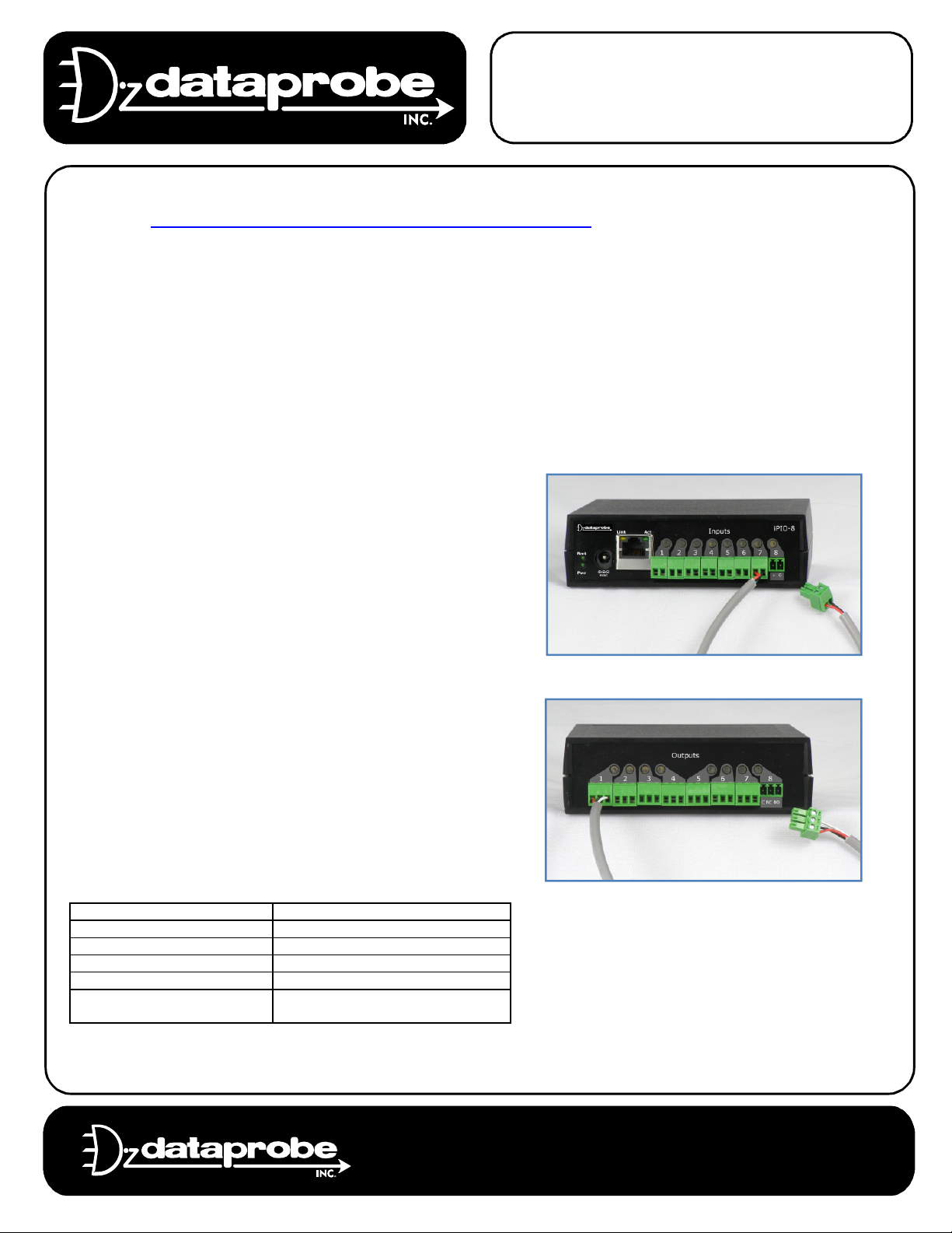
Hardware Installation
Inputs
Connect the inputs to the iPIO-8 using the removable
screw terminals. Connect only dry contact closures; relay
or switch contacts. Connect one leg to the G terminal and
the other to the + terminal.
For information on connecting wet contacts, consult the
complete manual before making any connections.
Relays
Connect to the iPIO-8 relays using the removable screw
terminals. Relays are Form C. Connect to the Common
(C), Normally Closed (NC) and Normally Open (NO) as
marked. When the iPIO-8 relay is in the Open Condition,
the Common is connected to the Normally Open. In the
Closed state, the Common and Normally Closed are
connected.
Relay Specifications
Rating (resistive) 0.5 A 120 VAC or 1 A 24 VDC
Maximum Carrying Current 2 A
Maximum Switching Power 60 AV, 24 W
Maximum Switching Voltage 120 VAC/60 VDC
Maximum Switching Current 1A
Life Expectancy 5 Million Operations Mechanical.
100K Operations at rated load
Technical Support:
Main:
201-934-5111
201-934-9944
tech@dataprobe.com
Website: dataprobe.com
Page 2
iPIO-8 Quick Start Guide Page 2
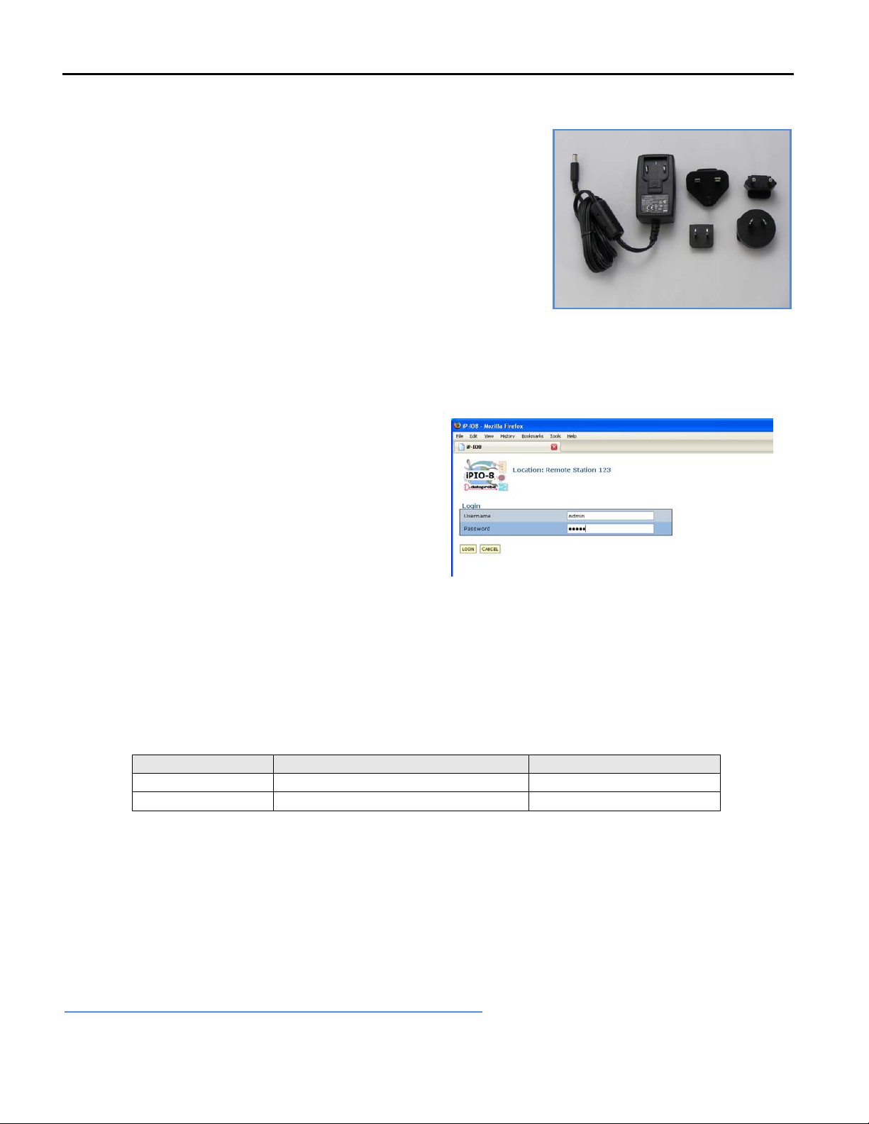
Power supply
The iPIO-8 is provided with a wall mounted power supply, item
1930075. This power supply is provided with four plug styles to
accommodate most locations. The plug for North America is pre
installed.
Network
Connect the network to the iPIO-8 with the Cat 5 cable, provided,
or suitable replacement. The Network connector on the iPIO-8
has two LED indicators. The orange LINK LED indicates a
successful connection to the network. The Green Activity (Act)
LED blinks to display network activity.
During power up sequence, Act LED will be solid on until boot process is complete. After boot, Act LED
blinking indicates network activity. Boot up takes about 20 seconds.
Power Supply 1930075 Included
WEB Page Access
The web pages provide status information on the
inputs and outputs of the iPIO-8, as well as provide
configuration for the unit. Open a browser to the
default or current IP address of the unit. Enter the
default username and password:
Factory Defaults:
Version 1.2 IP Address 192.168.1.254
Version 1.1 IP Address 192.168.0.254
User Credentials
User Type Default Username / Password Access
Administrator admin / admin View, Control and setup
General User user / user View and Control
iPIO-8 Login Page
Recover IP Address and Set Factory Defaults
Dataprobe provides a Setup Utility that
1) Discovers iPIO-8 units on the local network, and displays the current IP Address
2) Allows setting the IP Address
3) Resets to Factory Defaults
Download the Setup Utility from Dataprobe website at
http://dataprobe.com/ipio-web-relay-control.html?Resources
Ref: ipio8_1.20_qs ver: 2011-08-25
 Loading...