

Page 1
iBoot-PoE-P Quick Start Guide V180802N © 2018 Dataprobe Inc.
Hardware Connections
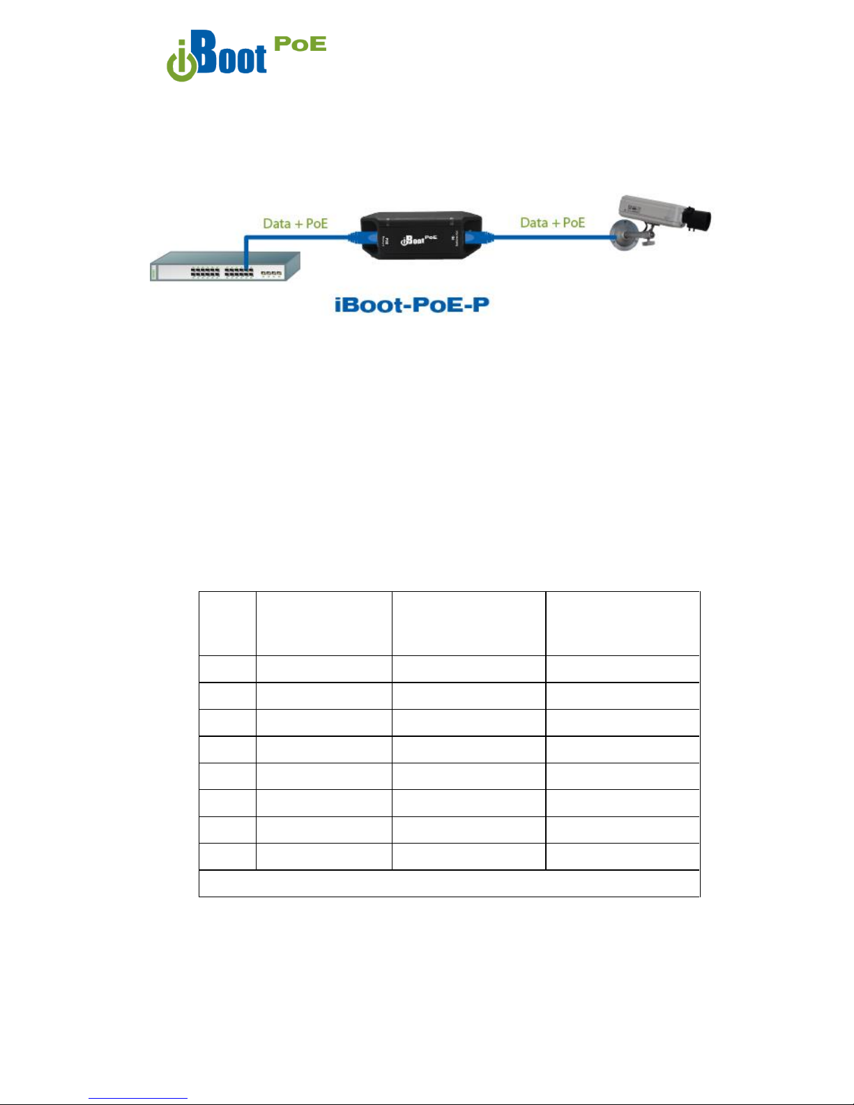
iBoot-PoE-P supports 10/100/1000 Ethernet using the cable supplied, or
other suitable unshielded twisted pair (Cat 5-6) cabling.
Power is derived from either the PSE, such as a PoE Network Switch or a
PoE Injector. The iBoot-PoE-P supports 802.3af Mode A, Mode B and
4PPoE wiring specifications, 9 – 72 VDC.
Connect the PoE OUT connector to the PoE Device to be
controlled (PD); Camera, Access Point, Phone, etc.
Connect the NET IN connector to the PoE Power source (PSE);
PoE Switch, Midspan or Injector.
PINS
Mode B
Voltage on Spare Pins
Mode A
Mixed Data and Voltage
4PPoE
(802.3bt Type 3 / 4 Draft
D1.2)
Voltage on all pins
1
DC +
DC +
2
DC +
DC +
3
DC -
DC -
4
DC +
DC +
5
DC +
DC +
6 DC -
DC -
7
DC -
DC -
8
DC -
DC -
Power Output on the PoE OUT connector will be identical to whatever mode is used on the NET IN
connector.
Quick Start Guide
PoE Switch or
PoE Injector
Page 2
iBoot-PoE-P Quick Start Guide V180802N © 2018 Dataprobe Inc.
LED Displays
NET IN Power is received by the iBoot-PoE from the PSE.
PoE OUT Power is delivered to the Controlled Device (PD).
Discover and Set the IP Address
If your network supports DHCP, the IP address of the iBoot will be automatically
assigned. Find the IP Address of the iBoot using either from the DHCP Router/Server
or use the Dataprobe Device Management Utility (DMU), available at
dataprobe.com/support-iboot-poe
See Page 3 for more in the DMU.
Web Browser PoE Power Control
Factory Default IP Address:
DHCP Set or 192.168.1.254
Factory Default Security Credentials:
User: admin Password: admin
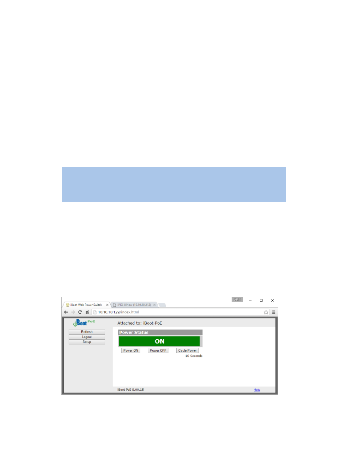
Point your browser to the IP Address of the iBoot-PoE, and then enter the
Administrator Username and Password. Once the user is validated, the Control and
Status is displayed.
To control the power, click on the appropriate button. During power cycling, the
Power Status bar will indicate the temporary status, with a blue background. Once
the cycle is complete, the status bar will revert to its original condition.
Page 3
iBoot-PoE-P Quick Start Guide V180802N © 2018 Dataprobe Inc.
Changing the IP Address
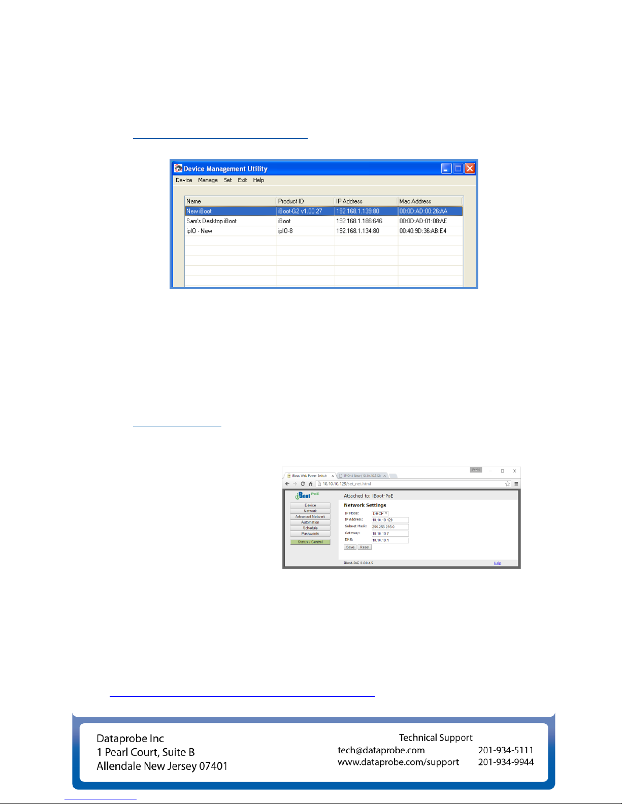
1. Device Management Utility
Obtain the Device Management Utility (DMU) from Dataprobe’s website at
dataprobe.com/support-iboot-poe
a. Open the DMU on a PC on the same physical network as the iBoot and select
Device > Discover to display the current IP Address of the iBoot.
b. Select Set > IP Address to change the address. The IP address can only be set
within the first two minutes of powering up the iBoot. The DMU will only work
with iBoots on the same physical subnets as the PC.
Complete instructions for the DMU are provided with the download, and in the full
iBoot-PoE Manual.
2. Web Page Setup
From the home page, click on
Setup, and then
Network. Enter the new
IP Address, Subnet Mask
and Gateway, then click
Save. Click the Reboot
button (or press the
reset button on the side of the unit to restart the iBoot-PoE with the new
settings. To lock the settings, select IP Mode = Static. If IP Mode remains
DHCP, the iBoot will obtain an address from a DHCP Server as soon as it finds
one.
The full manual covers all the automation and cloud control features
dataprobe.com/support-iboot-poe
 Loading...