

Page 1
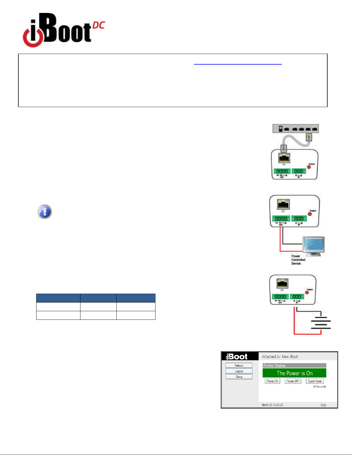
Fig.1
Connect Network
What’s Included
• iBoot-DC Unit
• Network Cable
• This Quick Start Guide
Quick Start Guide
Available Online at
dataprobe.com/support/iboot
• Complete Product Manual
• Device Management Utility
• Latest iBoot Firmware
• Software Developer Tools
Connections
1. Connect Network. iBoot-DC supports 10/100 Ethernet using the cable supplied, or other
suitable unshielded twisted pair (Cat 5) cabling. When power is connected to the iBoot-DC, the
Link (amber) and Activity (green) LEDs on the network connector indicate when the network
connection is properly established.
2. Connect Powered Device. Connect the device to be powered ON and OFF to the screw
terminals marked OUT. Connect the positive lead to the + and the negative (ground) to the - .
The Positive is switched. The standard connection is to the NO terminal. Screw terminal
assemblies are removable for easier connections. With the positive connected to the NO
terminal the power will be ON when the iBoot-DC displays ON. If the device has a power
switch, turn it on, to allow iBoot-DC to control the power.
Make sure that the load does not exceed 5 Amps for 5 - 29.9 VDC or
2 Amps for 30 - 48 VDC.
3. Connect Power Connect the DC power source to the terminals marked IN. Connect the
positive lead to the + and the negative (ground) to the - . The iBoot-DC is default power On.
The screw terminal assembly is removable for easier connection. The LED marked Output is
on when the power is connected to the NC terminal.
Web Browser Access
Factory Default IP Address: 192.168.1.254
Factory Default Security Credentials:
Role Username Password
Administrator admin admin
User user user
To access the iBoot from the default IP Address, requires the PC to be on the same local
network (IP Address 192.168.1.nnn). If it is not, change the iBoot IP
Address using one of the methods on the following page.
After pointing the browser to the IP Address of the iBoot, enter the
Administrator Username and Password to access the complete setup
features. Enter the User credentials to access only the power control.
Once the user is validated, the Control and Status is displayed.
To control the power, click on the appropriate button. During power
cycling, the Power Status bar will indicate the temporary status, with a
blue background. Once the cycle is complete, the status bar will
revert to its original condition.
Fig. 3 Connect Power
IBoot-DC quick start © 2011 Dataprobe Inc. V120423E
Fig. 4 Status and Control Page
Page 2
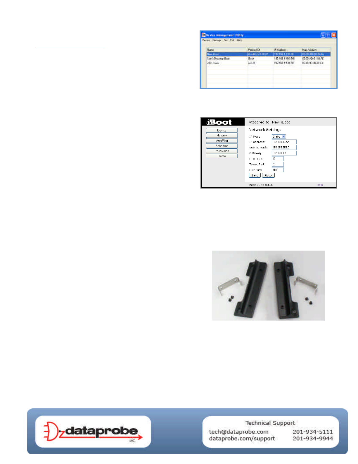
Changing the IP Address
F
ig. 5 Device Management Utility
1. Device Management Utility Obtain the Device
Management Utility (DMU) from Dataprobe’s website at
dataprobe.com/support/iboot. The DMU provides the easiest
means to find and configure your iBoot-DC for use. It can
discover all the iBoots on your network, display the current IP
address of each, and allow setting of any valid IP address.
Note: The IP address can only be set within the first two
minutes of powering up the iBoot. The Setup Utility will only
work with iBoots on the same local subnets as the PC.
The iBoot-DC Setup Utility can also be used to return an iBootDC to its Factory Default condition. This can be used to recover
an iBoot-DC with a lost password. Highlight an iBoot-DC from
the display and click Factory Defaults. This must also be done
within the first two minutes of powering up the iBoot.
Complete instructions for the DMU are provided with the
download, and in the full iBoot-DC Manual.
2. Web Page Setup From the home page, click on Setup,
then Network. Enter the new IP Address, Subnet Mask and
Gateway, then click Save. Click the Reboot button (or press the
reset button next to the power outlet LED) to restart the iBootDC with the new settings.
3. DHCP From the Home page, click on Setup, then Network.
Change the IP Mode from Static to DHCP. Click Save, then
Reboot. The iBoot-DC will obtain its network settings from the
server. Check the server, or use the Device Management Utility
to obtain the new settings.
Fig. 6 Network Setup Page
Mounting Options
iBoot-DC+ is suitable for desktop or shelf mounting. A mounting kit for
wall and DIN rail mounting is available. Order part:
1920034 Mounting Kit for iBoot-G2 Series
1920033 Mounting Kit
iBoot G2 Series
 Loading...