

Page 1
Port Selector & Relay Controller
Model 4PK-SCS
Operation Manual
INTRODUCTION
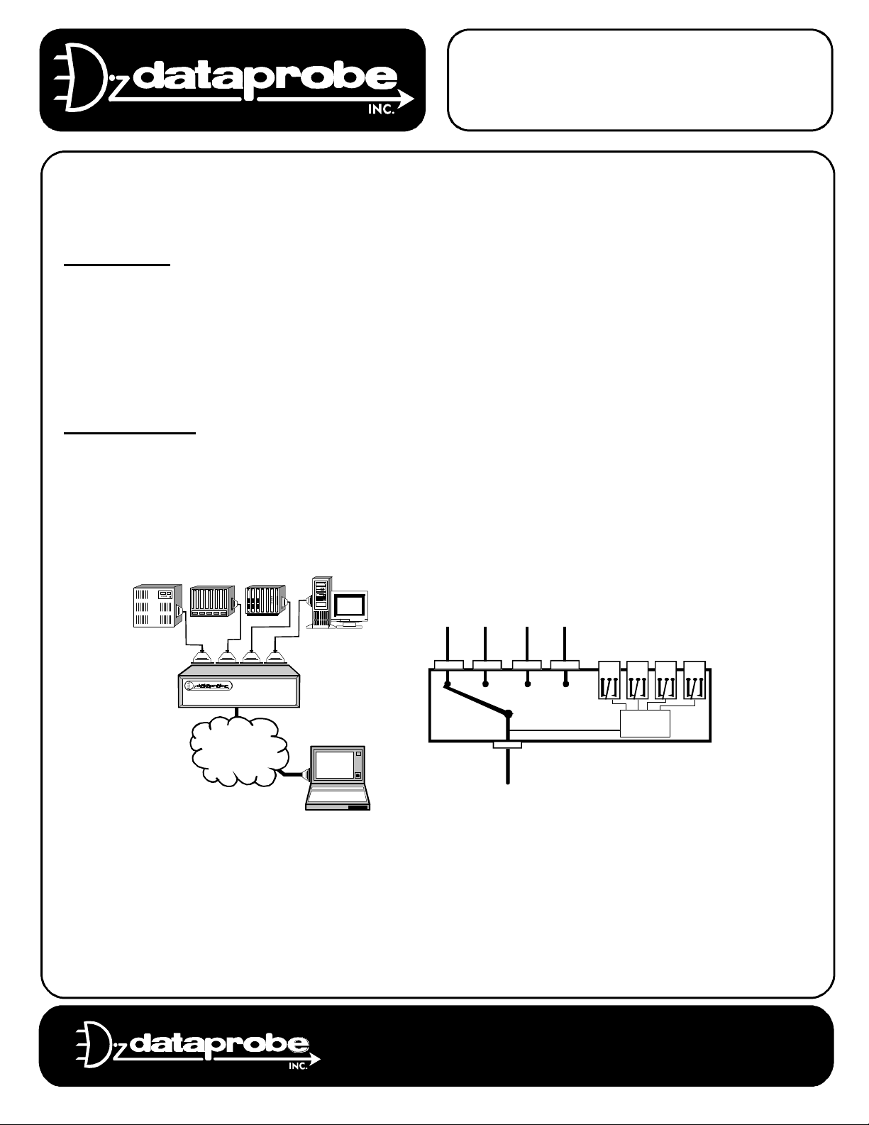
The 4PK-SCS is a serial switching system, capable of providing several functions:
Port Selector
As a port selector, the 4PK-SCS allows one Master RS-232 asynchronous channel to be selectively
switched to any of up to 4 ports. As a Port Selector, the 4PK-SCS can be used to provide access from
one modem or terminal to multiple systems. A typical use for the Port Selector is to access out-of-band
management ports on multiple devices. By using simple escape strings or easy to use menu
commands, the operator can select which port to access. Ports can also access the Master by raising a
control lead. While accessing a port, the 4PK-SCS is passive, allowing all data to pass until it receives
a user programmable command.
Relay Controller
As a relay controller, the 4PK-SCS accepts code or menu commands from its Master Port to energize or
de-energize four relays. These relays can be used, in turn, to control any device that responds to a
contact closure or open. When connected to Dataprobe supplied A/C or D/C power switches,
communications A/B switches or other devices, the 4PK-SCS allows remote control of many systems
through its Master RS-232 port.
Internal or
External
Modem
Supports Hardware #: 1-232-01 Rev D
REF: CAS\4PKSCS_110_V980326R.DOC
To 4 DTEs
A B
Master
Port
To DCE
C D
Relay
Control
Technical Support Hotline: (201) 967-8788
11 Park Place / Paramus, New Jersey 07652
TEL: 201-967-9300 FAX: 201-967-9090
Website: www. dataprobe.com Email: tech@dataprobe.com
Page 2

Model 4PK-SCS Page 2
OPERATION
The 4PK-SCS can be operated in four possible ways.
Menu Selection
By connecting to the Master Port, the user can switch to any of the four ports (A-D) or
operate any of the four relays. The menu system allows convenient naming of each
port and relay, as well as allowing setup of all 4PK-SCS parameters. A login
procedure protects the menu system.
Escape Code Sequences
(Page 6) The menu operation can be bypassed by transmitting escape codes to the
Master Port of the 4PK-SCS. These escape codes can be partially defined by the
user through the setup menus.
Lead Control
(Page 7) This option allows any of the four ports to access the master port by raising
its Request To Send (RTS) or Data Terminal Ready (DTR) control lead. This
capability is in addition to the menu selection as described above.
Manual Control
(Page 7) A front panel push-button allows local control of port selection.
MENU CONTROL
The 4PK-SCS is controlled principally through an ASCII terminal interface. By connecting to the modem
using a terminal or PC running terminal emulation software. The factory default parameters for
communication are:
9600 Bits per Second , 8 Data Bits , No Parity, 1Stop Bit (9600,8,n,1)
The 4PK-SCS incorporates automatic rate detection, allowing connection at 300-115.2K bps. Using the
default speed will allow the quickest access to the unit. To invoke the auto rate detector, send the Enter
key one or more times as necessary. When the rate is detected 4PK-SCS will respond the Security
Login Prompt:
Login >
Enter the Security Code. Three incorrect attempts to enter the security code will cause the 4PK-SCS to
terminate the call. When the correct code is entered, the Main Menu appears:
4PK-SCS Ver XXX
1) Port Selection
2) Relay Control
3) Programming
X) Logout
Enter >
Page 3

Model 4PK-SCS Page 3
1) Port Selection
This selection connects the Master Port to any of the four ports A through D. This brings up a Port
Selection Menu. Each port can be given a 24 character name. The default names are shown below:
A) PORT A
B) PORT B
C) PORT C
D) PORT D
X) Exit
Enter Port >
Once a port is selected, the 4PK-SCS will clear the screen and generate the following message:
x Selected (x=the programmed name of the port)
Enter ESC{PASSWORD}ESC to return to menu
At this point the Master Port is connected through to the port selected. The 4PK-SCS is passive to the
messages sent between the Master Port and the port selected. To terminate the session with the
current port and bring back the menu, enter the escape character plus the security code and another
escape character. i.e.
E
s
TEST
C
E
s
C
2) Relay Control
This selection allows control of the relays in the 4PK-SCS.
1) Eng SWITCH1
2) Eng SWITCH2
3) Den SWITCH3
4) Eng SWITCH4
# - Select relay to toggle
P# - Pulse relay
X - Exit
Enter >
Again, each relay can be named. Eng and Den display the current status of the relay, Energized or
De-energized. To toggle the relay, simply enter the relay number, followed by Enter.
The relay can also be cycled (pulsed) by entering P plus the number. (i.e. P1 to cycle relay number 1)
The length of time the relay pulses is preset through the programming menu. While the relay is cycling,
a message will be displayed.
Page 4

Model 4PK-SCS Page 4
3) Programming
1) Device labels
2) Password
3) Baud: 19200
4) Parity/Data: N,8
5) Lead: N
6) Resp: Y
7) Mode: Modem
8) Cycle time: 5
9) Time out: 0
X) Exit
Enter > 1
1) Device Labels. This allows changing of the screen labels for the ports and power control outlets.
A) PORT A
B) PORT B
C) PORT C
D) PORT D
1) SWITCH1
2) SWITCH2
3) SWITCH3
4) SWITCH4
X) Exit
Enter >
Enter the label to be changed. The current label is displayed along with a prompt for the new name.
Type in a new label and then confirm the selection. Labels can be up to 24 characters.
CURRENT LABEL PORT A PORT A
NEW LABEL PORT A > Your New Name
PORT LABEL CHANGED FROM PORT A
TO Your New Name
SAVE CHANGES? (Y/N) >
Page 5

Model 4PK-SCS Page 5
2) Password The password is used for login to the menu system and in every escape sequence.
The factory default is ‘TEST”. The security code may be 1 to 8 characters. These characters can be
any ASCII character except NULL (00 hex). To change the password, the current password must be
reentered. Then a prompt for a new password, then a confirmation of the new password.
LOGIN > TEST
ENTER NEW PASSWORD > TEST
RE-ENTER NEW PASSWORD > TEST
PASSWORD CHANGED
3) Baud Rate The 4PK-SCS is capable of operation from 300 BPS to 115200 BPS. Simply enter the
desired baud rate followed by the enter key. Valid Selections are:
300 600 1200 2400 4800 9600 19200 38400 57600 and 115200
The baud rate set only effects the code and menu control of the 4PK-SCS. Once connection is made to
a port, the 4PK-SCS is transparent to the speed and character format sent.
4) Parity and Data Bits The 4PK-SCS is capable of operating with a 7 or 8 bit data frame, and odd,
even ,or no parity. You need only set the parity, None, Even or Odd. The number of data bits and stop
bits is automatically determined.
5) Lead Control This selection determines whether control leads from the switched ports can be used
to access the Master Port. The factory default is lead control disabled. Select Yes or No.
6) Command Response The 4PK-SCS can send a response to escape sequences to let the operator
know that the switch has taken place. The factory default is responses disabled. Select Yes or No to
change this setting.
7) Modem or Terminal Mode Sets the 4PK-SCS for either Terminal or Modem use. Each time
selection 7 Mode is chosen, this setting toggles.
Modem Mode
The 4PK-SCS monitors the DCD lead from the Master Port. Once the call is established, send the
Escape to invoke the auto rate detector, if required, then the Enter Key to generate the Login
Prompt, or any valid control code. Three unsuccessful login attempts causes the 4PK-SCS to hang
up the modem. Use this setting when the 4PK-SCS is connected to a dial modem.
Terminal Mode
The 4PK-SCS does not monitor the connection status of the Master Port. This mode allows an
unlimited number of login attempts. Each time an enter key is received, a new login prompt is
issued. After three tries, the login prompt is suppressed to allow entry of control codes. Use this
mode for direct cable connections from a PC or Terminal to the 4PK-SCS.
8) Cycle Time Sets the length of time in a relay Cycle command. This time is set once for all relays
controlled. Selection of from 1 to 255 seconds are valid.
9) Time Out To prevent one port from dominating access to the Master Port and locking out other
selections, a time out feature is incorporated. With the timeout feature enabled, the 4PK-SCS monitors
the data activity received by the Master Port. When no data is received by the time as set, the currently
selected port is de-selected. Set the Time out from 1 to 99 minutes. Setting the Time Out to 0 (default
setting) disables the feature and allows unlimited time with no data received. The time out feature
affects all selection modes.
Page 6

Model 4PK-SCS Page 6
X) Exit the Programming Mode
Exit the programming menu and activate all current settings. If the baud rate and/or character format
have been changed, Exit will enable those changes.
X) Logout
From the Main Menu, this terminates the current session and a new connection to the 4PK-SCS will be
required. The calling system must terminate the session and hang up the modem.
ESCAPE CODE CONTROL
The 4PK-SCS allows direct computer control using simple ASCII strings. These codes can control the
port selection and relay operation. To access the 4PK-SCS for code control, enter the commands as
shown below. To invoke the auto-rate detector, send the Escape Key one or more times, until the 4PKSCS responds with 4PK-SCS READY. The syntax for all commands use the following:
E
s
C
<Sec> The Security Code (Default = TEST)
<x> The Port Letter (A - D)
<n> The Relay Number (1 - 4)
<EOT> The End of Text Character (Decimal 04 Hex 04 Ctl+D on the IBM Keyboard)
The Escape Character (Decimal 27 Hex 1B)
Select Port
Deselect Port
Toggle Relay
Query Status
Access Menu System
E
E
sC<Sec><x>
E
sC<Sec><EOT>
E
sC<Sec>R<n>
E
sC<Sec>?
sC<Sec>Es
C
Code Control Responses
The 4PK-SCS has an option to allow confirmation of switching commands. With this option enabled,
the 4PK-SCS will report back:
n selected where ‘n’ is the current port number or name (if programmed)
no ports selected when all ports are de-selected
r <status> Indicating the relay (number ‘r’) has been changed <status> will be
ENERG for energize or DE-ENERG for de-energized status.
n selected
1E 2D 3E 4D Response to Query Command. (E = Energized, D = De-energized)
Responses to Code Control commands are optional and set via the Programming Menu.
Page 7

Model 4PK-SCS Page 7
LEAD CONTROL OF PORTS
The 4PK-SCS provide the means for automatic port selection via control leads. The feature must be set
up prior to use. Any port can access the master by raising the RTS or DTR lead (jumper selectable)
provided no other port is already connected by Menu, Manual or Code Control. If another port is
connected the request is placed in queue. The queue is first in first out.
Once a port has been connected via lead control it remains in connected until the control lead has gone
low. If a port has been manually selected, and another port requests access, the manually selected
port remains active until it is deselected via the Menu, Code or Manual Control.
MANUAL CONTROL OF PORTS
The manual push-button switch on the front panel can be used for local control of the 4PK-SCS. Each
time the button is depressed, the port will cycle to the next port. To return the 4PK-SCS to automatic
operation, depress the push-button switch for over two seconds; all Port LEDs will turn off.
The Timeout feature, if enabled continues to operate when Manual control is established. To override
this feature, select Timeout = 0 from the Programming menu.
When manual control is selected, lead control is locked out. Escape codes will override the manual
selection only in Terminal Mode
Page 8

Model 4PK-SCS Page 8
INSTALLATION
Master and Switched Ports
Connection to the Switched A-D ports is made
using 25 pin D Subminiature connectors on the
rear of the unit. The following leads are supported
for Asynchronous communications:
Pin# Designation
2 Transmit Data
3 Receive Data
4 Request to Send
5 Clear to Send
6 Data Set Ready
7 Signal Ground
8 Data Carrier Detect
20 Data Terminal Ready
Typical
Port A-D
2 TD
3 RD
4 RTS
5 CTS
6 DSR
8 DCD
DTR20
7 SG
RTS
Mon.
Electronic
4 Way
Switch
Switch
Control
Code
Mon.
Master
Port
2 TD
3 RD
4 RTS
5 CTS
6 DSR
8 DCD
DTR20
7 SG
Figure 2
System Diagram
The four switched ports A-D are wired DCE (output
4 3 2 1
Relay Connections
data on pin 3,RD). The Master port is wired for as DTE.
To directly connect a terminal device to the Master
Port, a Null cable is required. Refer to Figure 3.
Null Connection to Terminal
2
4P-MAS
Master Port
3
4
5
6
7
8
20
Control Leads Required vary from device to
device. Consult your operations manual for
details on your specific needs.
2
3
4
5
6
7
8
20
Figure 3
Null Modem Connection
A
B
C
D
PORT
RTS
Port
Select
D
B
DTR
Port Status Relay Status
C
A
DCBA
MASTER
Board GND
K4 Common
K3 Common
K2 Common
K1 Common
4321
POWER
Figure 4
Component Location
(Not to Scale)
RTS / DTR Selection
Jumpers JP1 through JP4 allows selection of RTS (default) or DTR as the control lead used for Lead
Control. To access these jumpers, disconnect the power source and remove the top cover of the
4PK-SCS by loosening the two screws on the underside of the unit. The jumpers are located behind
the B and D Port Connectors. See Figure 4.
Ground / Common Pole
Any or All of the relay commons can be connected together and/or connected to board ground using
the header J9, located adjacent to the power LED. ( Used in conjunction with the 9 pin relay out )
Page 9

Model 4PK-SCS Page 9
Power Control Relay Connection
Connection to the four Power Control relays are made using four RJ11 modular jacks located on the
rear of the unit. The modular jacks are marked for Relays 1 - 4. Refer to Figure 4, Component
Locations. Dataprobe supplies A/C power and communications switches that can be used with the
4PK-CAS. The pin-outs of the modular jacks are designed to connect directly to Dataprobe’s relay
switches. In some cases a control cable, available from Dataprobe is required.
Model Description Connect to 4PK-CAS with
K-12A A/C Power Switch RJ11 Cord supplied with K-12A
K-515A 4 Outlet Power Strip Cable Supplied with K-515A
K-AB Series Communications A/B Cable SL-K7 Ordered Separately
To connect any other equipment to the relays, the following pin-out should be used:
Pin # Designation
2 Normally Open
5 Common
1
2 NO
3
4
5 COM
6
Figure 5
Modular Jack Pinout for
Relay Connections
DB9 Female Connector for relay connection. These connections are in addition to the RJ11
connectors.
Pin # Designation
6 7 8 9
1 Normally Open Relay #1
2 Normally Open Relay #2
3 Normally Open Relay #3
4 Normally Open Relay #4
1 2 3 4 5
5 Board Ground
INTERNAL MODEM OPTION
Dataprobe offers the following internal
modem options with the 4PK-SCS:
MOD-24 2400bps Modem
MOD-144 14.4 Kbps Modem
MOD-336 33.6 Kbps Modem
These modem options, when ordered
with the 4PK-SCS are supplied factory
installed. They can also be ordered
separately for field installation.
Information on field installation is
supplied with the modem.
Modular
Adaptor
MA-CAS
Relay
Control
MASTER
Modular
Cord
1 2 3 4
A AAA
C
A
1-4
D
B
Dial Line
Figure 6
Dial Line Connection
with Internal Modem
Connection to the dial line is made using a RS-232 to Modular Adapter, Model MA-CAS, supplied with
the modem. This adapter connects to the Master Port and to an RJ11 Modular Jack. The modem’s
FCC registration and AT command set are supplied in a separate document.
Page 10

Model 4PK-SCS Page 10
SPECIFICATIONS
Physical
8” Wide x 6.25” Deep x 3.25” High.
Power
120VAC via Wall Mounted Power Supply. UL/CSA approved.
Communications
Speed: 300 to 115,200 bps.
Character Format: 8 data, no parity, 1 stop bit / 7 data even or odd parity, 1 stop bit.
Interface: RS-232 Asynchronous .
Connectors
Ports A through D: 25 pin D Subminiature, Female.
Master Port: 25 pin D Subminiature, Male. Pins Supported: 1-8, 20.
Relays
Form C (SPDT)
Rating 0.5A @ 120VAC or 1A @ 24VDC
Switching Power 60VA Max 50uW Min
Switching Voltage 120VAC or 60VDC Max 1VDC Min
Switching Current 2A Max 1mA Min
Resistance 100 milliohms (initial value)
Life Expectancy 5 Million Operations Mechanical
100K Operations at rated load
Page 11

Model 4PK-SCS Page 11
TECHNICAL SUPPORT, RETURNS & WARRANTY
Dataprobe Technical Support is available 8:30AM to 5:30PM ET to assist you in the installation and
operation of this product. To obtain Technical Support call our Tech Support Hotline at 201-967-8788,
or Email us at tech@dataprobe.com. Please have the following information available when you call:
• Model of Product
• Serial Number
• Data of Purchase
• Name of Seller (if other than Dataprobe)
If you purchased this product through an Authorized Dataprobe Reseller, you should contact them
first, as they may have information about the application that can more quickly answer your questions.
WARRANTY
Seller warrants this product, if used in accordance with all applicable instructions, to be free from
original defects in material and workmanship for a period of One Year from the date of initial purchase.
If the product should prove defective within that period, Seller will repair or replace the product, at its
sole discretion.
Service under this Warranty is obtained by shipping the product (with all charges prepaid) to the
address below. Seller will pay return shipping charges. Call Dataprobe Technical Service at (201) 9678788 to receive a Return Materials Authorization (RMA) Number prior to sending any equipment back
for repair. Include all cables, power supplies and proof of purchase with shipment.
THIS WARRANTY DOES NOT APPLY TO NORMAL WEAR OR TO DAMAGE RESULTING FROM ACCIDENT,
MISUSE, ABUSE OR NEGLECT. SELLER MAKES NO EXPRESS WARRANTIES OTHER THAN THE
WARRANTY EXPRESSLY SET FORTH HEREIN. EXCEPT TO THE EXTENT PROHIBITED BY LAW, ALL
IMPLIED WARRANTIES, INCLUDING ALL WARRANTIES OF MERCHANT ABILITY OR FITNESS FOR ANY
PURPOSE ARE LIMITED TO THE WARRANTY PERIOD SET FORTH ABOVE; AND THIS WARRANTY
EXPRESSLY EXCLUDES ALL INCIDENTAL AND CONSEQUENTIAL DAMAGES.
Some states do not allow limitations on how long an implied warranty lasts, and some states do not
allow the exclusion or limitation of incidental or consequential damages, so the above limitations or
exclusions may not apply to you. This warranty gives you specific legal rights, and you may have other
rights which vary from jurisdictions to jurisdiction.
WARNING: The individual user should take care to determine prior to use whether this device is
suitable, adequate or safe for the use intended. Since individual applications are subject to great
variation, the manufacturer makes no representation or warranty as to the suitability of fitness for any
specific application.
Dataprobe Inc.
11 Park Place
Paramus, NJ 07652
 Loading...