

Page 1
92-2491-01 Rev.B
Media Hubs
Page 2

Page 3
Overview
This document describes the contents and installation of the Media Hub options for the M-Class MII
printer. Only qualified service personnel should perform this installation. After verifying the kit contents
and the tools needed, follow the steps below to install the option.
Contents
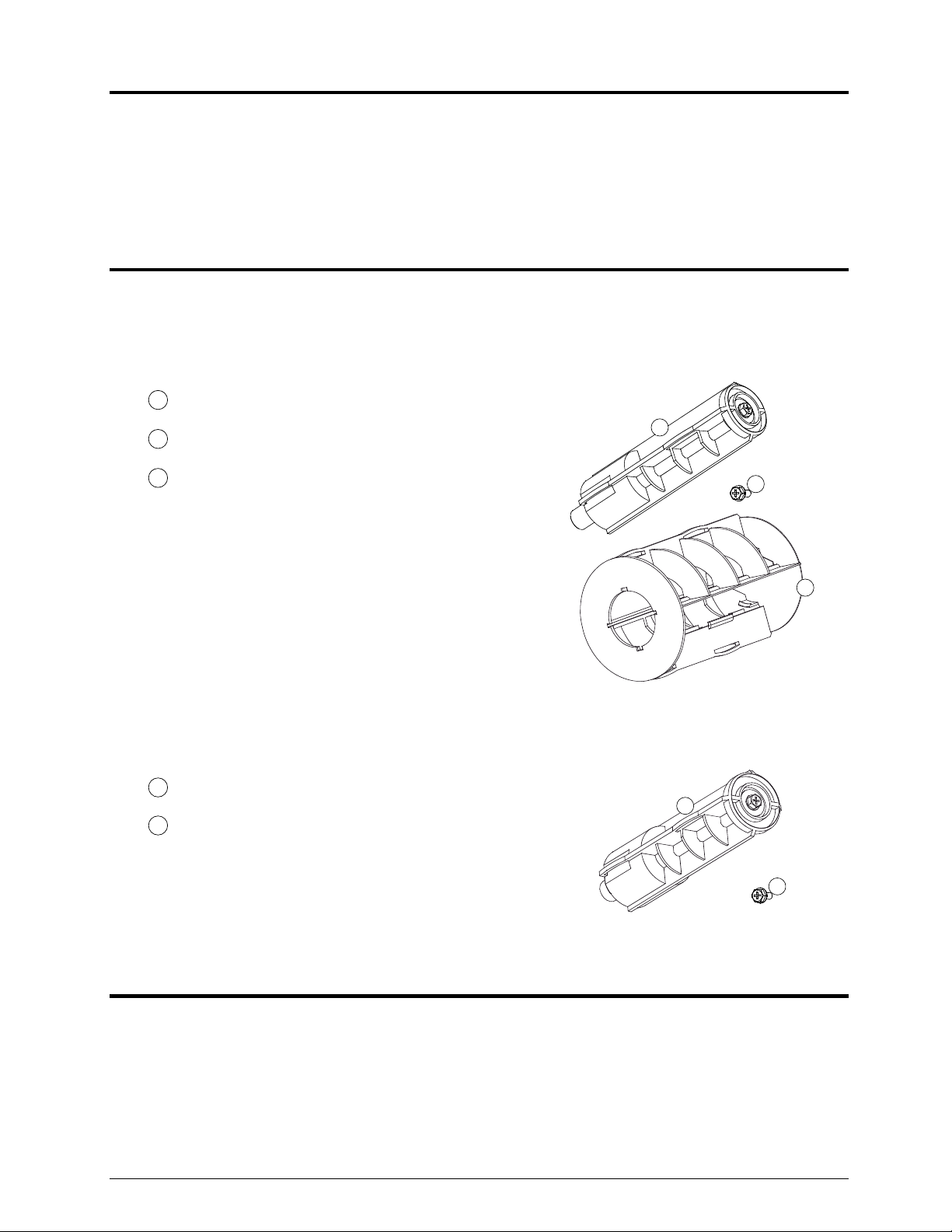
The contents of the Media Hub Kit differ according to kit number:
(3-Inch Media Hub Kit) contains the following items:
1
1.5-Inch Media Hub Assembly
2
Philips Screw
3
Hub Adapter
1
2
(40-mm Media Hub Kit) contains the following items:
1
40-mm Media Hub Assembly (P/N 15-3199-01)
2
Philips Screw (P/N 10-2903-04)
Tools Required
A Phillips screwdriver is needed for installation.
3
1
2
2
Page 4

Installation
CAUTION
A) Turn OFF the Power Switch
and unplug the power cord
from the AC Receptacle.
Disconnect the interface
cable(s).
Only qualified service personnel should perform this installation. Always wear a wrist
strap and follow standard ESD prevention measures when handling any printer
circuit card assembly.
Power Switch
AC Receptacle
B) Remove the Cover Screws
on the outside of the printer.
Cover Screws
Cover
C) Raise the Cover. Loosen the
Cover Screws on the
Centerplate then remove the
Cover.
Cover Screws
Centerplate
3
Page 5

D) Disconnect the cables from
the Main Logic Card.
Main Logic
Card
E) Remove the Screws that
secure the Main Logic Card
and the Fill Plate to the Card
Cage. Remove the Fill Plate
then slide the Main Logic
Card out of the printer.
Main Logic
Card
Screws
Fill
Plate
Card Cage
Centerplate
F) Remove the Hanger Screws
that secure the Media
Hanger to the Centerplate
and then remove the Media
Hanger.
Media
Hanger
4
Hanger
Screws
Page 6

Main Logic Card
G) Slide the Main Logic Card
into the Card Cage and
replace the Fill Plate. Secure
the Main Logic Card and the
Fill Plate using the previously
removed Screws. Reconnect
all the cables to the Main
Logic Card.
H) Remove the Ground Strap
Screw and Lock Washer,
four Power Supply Screws,
and two Line Filter Screws.
Remove the Line Filter
Bracket and then remove the
Power Supply.
Power Supply
Screws
Line Filter
Screws
Line Filter
Bracket
J11
J16
J4
Ground Strap
Screw and Lock Washer
Media Hub Assembly
J5
J9
J12
J7
J6
Power Supply
J14
J10
J8
I) Place the Media Hub
Assembly*(Item 1) into the
Hub Mount. Secure the
Shaft to Hub Mount using
the Screw (Item 2), ensuring
that both are completely
tightened before proceeding.
Shaft
Hub Mount
* 3-Inch Media Hub Kit installers – see the note at the end of this document.
5
Screw
Page 7

J) Install the Power Supply
then place the Line Filter
Bracket onto the Line Filter.
Secure the Power Supply
using the Power Supply
Screws and the Line Filter
Screws.
Power Supply
Screws
Line Filter
Bracket Screws
Line Filter
Line Filter
Bracket
Power Supply
K) Insert the Ground Strap
Screw into the Lock Washer
and the Ground Strap Lug.
Then secure the Ground
Strap Lug to the chassis
using the Ground Strap
Screw and Lock Washer.
L) Check all Power Supply cable
connections then place the
Cover onto the printer. Install
and tighten the Cover
Screws on the outside of the
printer.
Ground Strap Screw
and Lock Washer
Ground Strap Lug
Cover Screws
6
Page 8

M) Tighten the Cover Screws on
the Centerplate.
Cover Screws
Centerplate
N) Connect the interface
cable(s). Plug the power cord
into the AC Receptacle and
turn ON the Power Switch.
This completes the
installation process; refer to
the Operator’s Manual for
media loading instructions.
Note: The 3-Inch Media Hub
Kit is configurable:
To install the Hub
Adapter (Item 3),
align the Tabs then
slide the Hub
Adapter over the
1.5-Inch Hub
Assembly until it
seats in place; or,
To remove the Hub
Adapter, grasp and
pull.
Power Switch
AC Receptacle
Hub Adapter
Tabs
Tabs
1.5-Inch Hub
Assembly
Tabs
Tabs
7
 Loading...