

Page 1
Programmer’s Manual
Covers the following models:
MP Nova
MP Compact Mark II
MP Compact Mobile Mark II
Page 2

Information in this manual is subject to change without notice and does not represent a commitment on
the part of Datamax-O’Neil Corporation. No part of this manual may be reproduced or transmitted in any
form or by any means, for any purpose other than the purchaser’s personal use, without the expressed
written permission of Datamax-O’Neil Corporation.
© 2009 by Datamax-O’Neil Corporation
Part Number: 540340.03
Page 3

PROGRAMMER’S REFERENCE MANUAL
Table of Contents
Table of Contents
Labelpoint features: ..........................................................................................2
Scalable text field.............................................................................................. 7
Bitmap text field (deprecated) ........................................................................10
The text to be printed ...................................................................................... 11
Fixed text ........................................................................................................11
Variable information.......................................................................................11
Counters.......................................................................................................... 11
Date and time .................................................................................................. 11
Best-before date ..............................................................................................12
Check digits ....................................................................................................13
Line breaks......................................................................................................13
Reverse video.................................................................................................. 13
Barcode symbologies...................................................................................... 16
Bar code interpretation.................................................................................... 19
Defining a 2D barcode field............................................................................ 19
2D barcode symbologies................................................................................. 20
Code 128 ......................................................................................................... 22
RSS .................................................................................................................23
RSS-14 ............................................................................................................ 23
RSS-14 Truncated...........................................................................................23
RSS Limited.................................................................................................... 23
RSS Expanded ................................................................................................23
MaxiCode........................................................................................................ 24
Structured Carrier Message.............................................................................24
Modes.............................................................................................................. 24
Escape Sequences ...........................................................................................25
Data encodation ..............................................................................................25
Structured Append ..........................................................................................25
Code PDF417.................................................................................................. 26
Security level ..................................................................................................26
QR Code..........................................................................................................28
Correction level............................................................................................... 28
Masking pattern ..............................................................................................28
Other escape sequences...................................................................................28
Changing a single variable..............................................................................31
Clearing variable information......................................................................... 32
Clearing the layout..........................................................................................32
Print command................................................................................................ 32
Dormant print (or trigged printkey) ................................................................ 32
Status request 1 ...............................................................................................33
Out of paper ....................................................................................................33
Label not removed (LTS)................................................................................33
Printer restarted...............................................................................................33
No paper in label sensor.................................................................................. 33
Out of ribbon................................................................................................... 34
Heap error ....................................................................................................... 34
Status request 2 ...............................................................................................34
Page 4

PROGRAMMER’S REFERENCE MANUAL
Table of Contents
Stopped on label gap.......................................................................................34
Print incomplete..............................................................................................34
Cool down state...............................................................................................34
Last paper movement type.............................................................................. 34
Layout outside label........................................................................................35
Status request 3 ...............................................................................................35
Operating parameters error .............................................................................35
Internal print button ........................................................................................ 35
Label stock...................................................................................................... 35
Status request 4 ...............................................................................................36
Out of paper ....................................................................................................36
Label not removed (LTS)................................................................................36
Out of ribbon................................................................................................... 36
Head lifted....................................................................................................... 36
Internal print button ........................................................................................ 36
Printer restarted...............................................................................................36
Status request 8 ...............................................................................................37
LTS installed...................................................................................................37
I2C board installed...........................................................................................37
Cutter installed................................................................................................ 37
Black mark photocell...................................................................................... 37
PHD board installed........................................................................................37
Barcode displacement..................................................................................... 52
HTML version ................................................................................................53
Text version ....................................................................................................53
Document start................................................................................................54
Document end................................................................................................. 54
Cutter mode..................................................................................................... 55
Cutting command............................................................................................ 55
Label-taken sensor (LTS) ...............................................................................55
Local printer....................................................................................................56
Network printer...............................................................................................56
Macros.............................................................................................................57
Loading a macro .............................................................................................57
Deleting a macro............................................................................................. 57
Executing a macro...........................................................................................57
Auto macro......................................................................................................57
Graphics.......................................................................................................... 58
Loading a graphics file....................................................................................58
Deleting a graphics file ................................................................................... 58
Counters.......................................................................................................... 59
Initialising counters......................................................................................... 59
Retrieving information about counters ........................................................... 60
Paper feed........................................................................................................60
Automatic reverse feed ...................................................................................60
Paper feed on command..................................................................................60
True two-way communication........................................................................ 61
ENQ - ACK/NAK...........................................................................................61
Page 5

PROGRAMMER’S REFERENCE MANUAL
Table of Contents
Data Format ....................................................................................................64
Segment record ............................................................................................... 64
Data record...................................................................................................... 64
End record.......................................................................................................65
Labelpoint load graphics command................................................................ 66
Graphics format ..............................................................................................66
Control Characters ..........................................................................................67
Limitations...................................................................................................... 67
Code page 850, MS-DOS Latin 1................................................................... 68
Swedish/Finnish character set (7-bit)..............................................................68
German character set (7-bit) ...........................................................................69
UK character set (7-bit) ..................................................................................69
French character set (7-bit) ............................................................................. 70
Norwegian/Danish character set (7-bit).......................................................... 70
Spanish character set (7-bit)............................................................................71
Italian character set (7-bit).............................................................................. 71
Code page 861, MS-DOS Icelandic................................................................72
Code page 1252, Windows Latin 1 (ANSI).................................................... 73
Code page HP Roman-8..................................................................................74
Code page 852, MS-DOS Latin 2 (Central Europe)....................................... 74
Code page 1250, Windows Latin 2 (Central Europe)..................................... 75
Code page 855, MS-DOS Cyrillic ..................................................................75
Code page 1251, Windows Cyrillic (Slavic) .................................................. 76
Code page 1253, Windows Greek ..................................................................76
Code page 1254, Windows Latin 5 (Turkish)................................................. 77
Code page 1257, Windows Latin 6 (Baltic Rim)............................................ 77
Code page ISO 8859-2....................................................................................78
Command summary........................................................................................ 79
Status requests................................................................................................. 79
!S1................................................................................................................... 79
!S2................................................................................................................... 80
!S3................................................................................................................... 80
!S4................................................................................................................... 81
!S8................................................................................................................... 81
Service Commands .........................................................................................82
Printer configuration ....................................................................................... 84
Bar code symbologies..................................................................................... 87
Example 1a - The shoe example................................................................................. 88
Example 1b - The shoe example with variables ......................................................... 89
Page 6

PROGRAMMER’S REFERENCE MANUAL
The Labelpoint command language
Introduction
The thermal printer family features a simple yet powerful command language, Labelpoint II
(LP II). This allows the printers to be controlled from most computers. Most common bar code
symbologies are available. Text and bar codes can be printed in all four directions
simultaneously. Counters for consecutive numbering are available and an integral real-time
clock allows labels to be time-stamped at print time.
Labelpoint II uses only printable ASCII characters to allow commands to be easily
manipulated in the host computer. This also avoids problems with control characters that some
computer systems reserve for internal use.
Labelpoint features:
• Easy-to-use command language
• Prints text, bar and matrix codes, lines, boxes and graphics
• Contains character sets for all major European languages
• Many barcode symbologies are standard
• Several 2-dimensional (matrix) codes
• Ten scalable fonts as standard (uses Unicode character set internally to be able to
use all latin and cyrillic characters)
• TCP/IP support (LPD, RTELNET)
• Terminal Server functionality (COM1 and/or COM2 connected to the network)
• Easy-to-use configuration menu accessible through COM ports, Telnet port or by
using a common web-browser.
• Date and Time symbols
• Ten onboard counters for consecutive numbering
Page 2
Page 7
PROGRAMMER’S REFERENCE MANUAL
The Labelpoint command language
The Labelpoint command language
Labelpoint consists of a number of commands for creating a label layout, configuring the
printer, checking the printer set-up etc.
The printer receives characters and interprets them as commands or as data. A command
instructs the printer to perform some action, e. g. create a field in the label layout. Data can, for
example, be variable data that is to be included in the print-out, or it can be a sequence of
commands that are to be stored in the printer file system.
The printer acts on incoming data on a line-by-line basis. Input data is buffered until the
end-of-line character is received. The default end-of-line character is CR (carriage return,
ASCII 13
interpreted. If the line begins with the command character it is treated as a command.
= 0D16). When an end-of-line character is received, the line of data received is
10
A command line starts with an ! character (ASCII 33
specifying the command type. Some commands take parameters.
Note! The ‘!’ character must be the first character on the command line. Otherwise the
line will look like a data line.
Example
To print one label, type:
!P1
To print 100 labels, type:
!P100
Some commands assume a default value if a parameter is omitted. The command
to print one label may be given as:
!P
The available commands and programming procedures are described in the following
sections.
Case is significant for command characters. If the wrong case is used the printer will ignore
the command.
Note! All commands must be terminated by the end-of-line character (normally CR.).
The end-of-line character will not be shown in the examples in this manual.
= 2116) , followed by a character
10
Page 3
Page 8
PROGRAMMER’S REFERENCE MANUAL
Label layout definition commands
Label layout definition commands
This chapter will explain label designing basics and commands used to create labels in
Labelpoint.
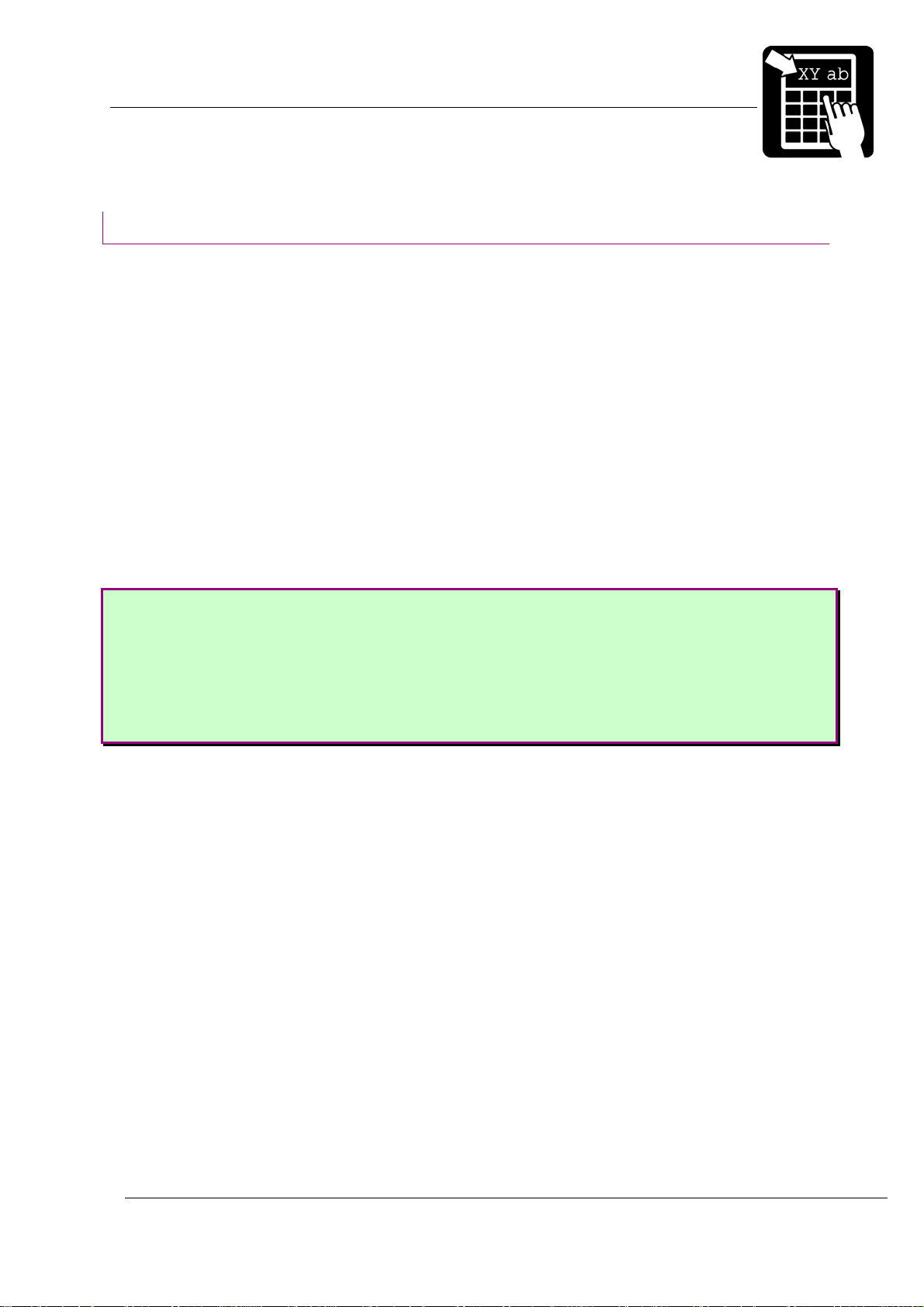
The print area
All items (fields) to be printed on a label must be defined with their position on the paper.
The coordinate system is shown below:
paper feed direction
Y
X
The X coordinate grows across the print head, from right to left, viewing the printer from the
front. The Y coordinate grows as the paper is fed out.
All fields have a print direction, which is specified by the up vector. This is the "natural" up
direction of the field. (The text on this paper has its up vector pointing to the top of the paper.)
The terminology of the compass is used to specify the up vector. "North" is defined as the
paper feed direction. Text printed with up vector =
the top of the characters appearing first. Up vector
left-most character of the text is the first to appear, etc.
The position of a field on the paper is given as its baseline and position.
The baseline is the coordinate of the bottom of the field. For fields with up vector
the baseline is the Y coordinate; for fields with up vector
fields the baseline is at the base of non-descending characters, so that descending characters
(e.g. 'j', 'g', and 'y') will extend below the baseline. ('Above' and 'below' always refer to the up
vector of the field, and may thus be different physical directions, depending on the up vector of
the field.)
The position parameter determines the position of the field in the direction perpendicular to
the up vector, i. e. sideways. It may be given as the position of either the left end, the right
end, or the center of the field.
N (north) is printed across the paper, with
E (east) is turned 90° clockwise, so that the
N or S,
E or W it is the X coordinate. For text
All coordinates are given in 1/10 of a millimeter. The same applies for the
length of the bars in a code, and the height and width of a black box.
Page 4
Page 9

PROGRAMMER’S REFERENCE MANUAL
Label layout definition commands
Building a label layout
Before printing, the label layout must be defined. The layout defines the position and other
attributes (size, font, barcode symbology etc.) of each item to be printed. When the print
command is issued, the resulting print picture is printed out. The print format can be changed
at any time.
The text to be printed can be fixed or variable. Fixed text is part of the layout and does not
change until the layout is changed. Variable text can be entered for each printout of a layout,
without changing the layout.
When the label layout with fixed data has been loaded in the printer the variable data (i. e.
text that changes for each printout) is sent, followed by the print command to print one or more
labels.
!F command defines a layout field, i. e. an item to be printed.
The
A layout field is one of the following:
• one or more lines of text
• a barcode or matrix code
• a line, box or frame
• graphics
When a ‘
layout is built by defining all the fields to be printed. A text, barcode, matrix code or graphics
field may include fixed or variable text, or both.
!F’ command is received the printer adds the new field to the label layout. A label
Page 5
Page 10
PROGRAMMER’S REFERENCE MANUAL
Label layout definition commands
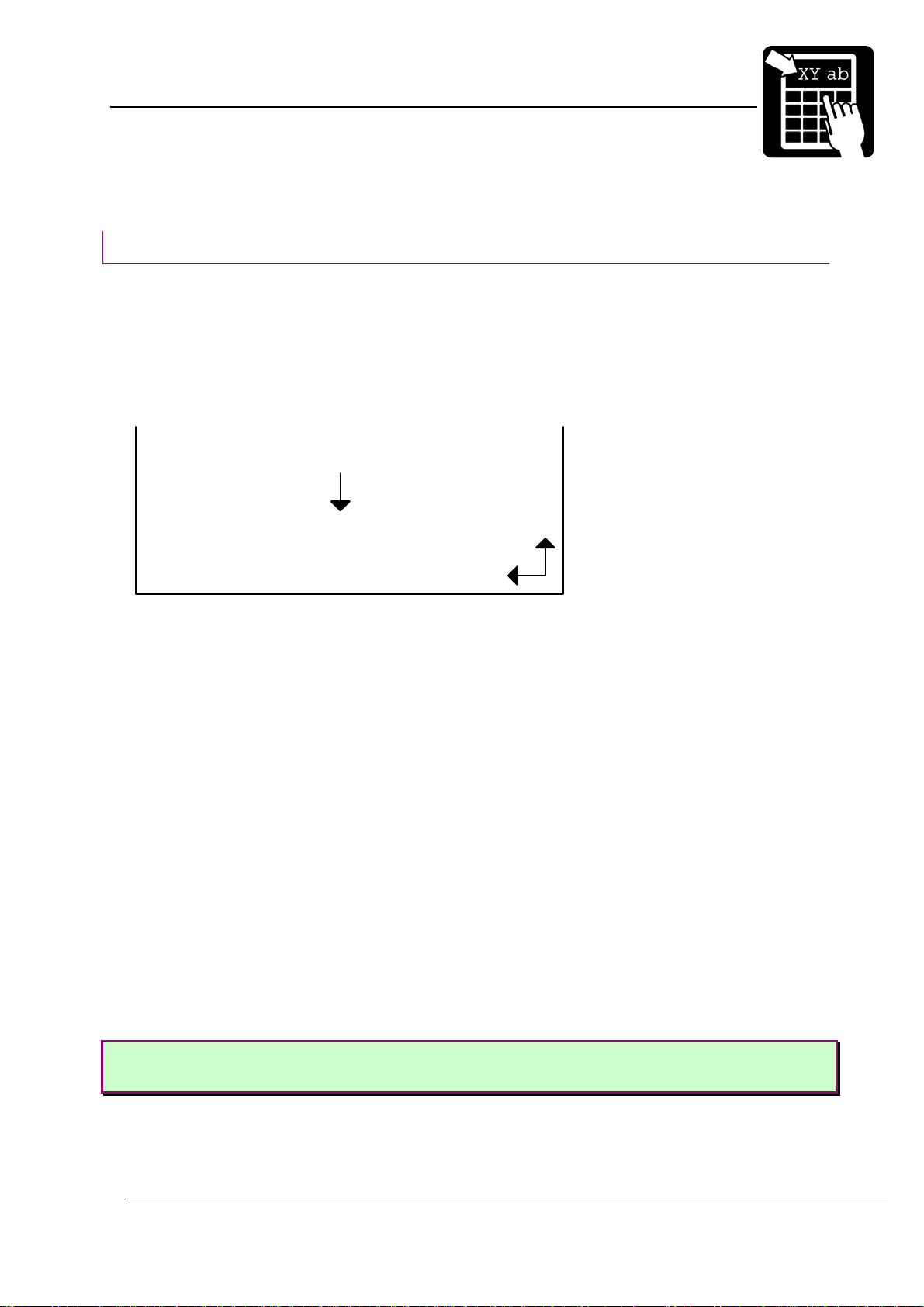
The shoe example:
!C
!Y24 60
!Y35 10
!Y42 1
!F T N 100 100 L 14 0 94030 "TESTLABEL"
!F T N 200 100 L 10 0 94021 "PRICE: 65.00"
!F T N 250 100 L 10 0 94021 "SIZE: 42"
!F C N 450 100 L 150 2 41 "65.00"
!F B N 120 90 L 80 240
!P
When sending this layout to the printer, you’ll get a 5 x 4 cm label with a black box at the
top, the size and price of the shoe, and a barcode at the bottom.
See further explanation for this example in section ‘Print Example’ at the end of this
document.
Page 6
Page 11
PROGRAMMER’S REFERENCE MANUAL
Label layout definition commands
Defining a text field
There are two different types of textfields, scalable and bitmap fields. Bitmap text fields are
deprecated, that is, not recommended for new designs but kept in this manual for backward
compatibility.
Scalable text field
The benefit of using scalable fonts is its possibility to use the highest possible resolution for
the letters, independent of the size defined. This is due to the font’s appearance being
calculated in run time.
Syntax I
!F S <u> <b> <p> <a> <h> <s> <f> [wa] <“text“>
Syntax II
!F S <u> <b> <p> <a> <h> <w> <f> [s] <“text“>
Note! Parameters enclosed in <> are required and parameters enclosed in [] are
optional.
The parameters have the following meanings:
<u> Defines the direction of printing as the ‘up’ direction of the printed characters. One
upper-case character (N, E, S, or W).
<b>
<p>
<a> The alignment relative to the position. One upper-case character.
<h> The font height, in points.
<w>
<f> The font number. See tables below.
<s>
<wa> Width adjustment, in percent. Valid values are 50 (%) to 200 (%).
The baseline of the field, in
1
The position, in
L = left end of the field aligned at p.
R = right end of the field aligned at p.
C = the field is centered around p.
The font width in points. To get normal character width, set parameter w to the same
value as parameter h.
Inter-character spacing in
To get normal character width, set parameter wa to 100.
This parameter is only used in syntax I. (Optional)
/10 mm.
1
/10 mm.
1
/10 points. (Optional in syntax II)
<”text”>
Specifies the text to be printed. The text must be enclosed in double quotes (
").
Page 7
Page 12
PROGRAMMER’S REFERENCE MANUAL
Label layout definition commands
Labelpoint uses Agfa Universal Font Scaling Technology® to generate scalable font
characters. Fonts are stored in either Agfa MicroType™ format or TrueType format.
There are ten fonts included in the printer. The printer also emulates a number of italic fonts
styles for sans serif fonts.
PCL typeface name PCL typeface number
Univers Medium
Univers Italic (emulated)
Univers Bold 1 94023
Univers Bold Italic (emulated) 1 94024
Univers Condensed Medium 2 94029
Univers Condensed Italic (emulated) 2 94039
Univers Condensed Bold 2 94030
1
1
94021
94022
Univers Condensed Bold Italic (emulated) 2 94040
CG Times 1 92500
CG Times Italic 1 92501
CG Times Bold 1 92504
CG Times Bold Italic 1 92505
Letter Gothic Bold 2 93779
Letter Gothic Bold Italic (emulated) 2 93780
Coronet (script) 2 90249
For faster printouts from MS-Windows systems, the Arial fonts and the Times New Roman
fonts are also emulated. On next page is a list with the fonts and their corresponding font
number:
1
Latin 1, 2, 5, 6, Greek and Cyrillic characters available
2
Latin 1, 2, 5 and 6 characters available
Page 8
Page 13
PROGRAMMER’S REFERENCE MANUAL
Label layout definition commands
PCL typeface name PCL typeface number
Arial (emulated) 24459
Arial Italic (emulated) 24460
Arial Bold (emulated) 24461
Arial Bold Italic (emulated) 24462
Times New Roman (emulated) 24455
Times New Roman Italic (emulated) 24456
Times New Roman Bold (emulated) 24457
Times New Roman Bold Italic (emulated) 24458
Page 9
Page 14
PROGRAMMER’S REFERENCE MANUAL
Label layout definition commands
Bitmap text field (deprecated)
Bitmap text fields are deprecated. This section is kept for backward compatibility reasons.
Use scalable fonts instead.
Syntax
!F T <u> <b> <p> <a> <h> <w> <f> <”text”>
Note! Parameters enclosed in <> are required and parameters enclosed in [] are
optional.
The parameters have the following meanings:
<u> Defines the direction of printing as the ‘up’ direction of the printed characters. One
upper-case character (N, E, S, or W).
<b>
<p>
<a> The alignment relative to the position. One upper-case character.
<h> The height expansion of the characters, 1 – 16.
<w> The width expansion of the characters, 1 – 16.
<f> The logical number of the font to be used for printing, 1 – 7.
<text>
The baseline of the field, in
1
The position, in
L = left end of the field aligned at p.
R = right end of the field aligned at p.
C = the field is centered around p.
Specifies the text to be printed. The text must be enclosed in double quotes (
/10 mm
1
/10 mm.
Bitmap font name Bitmap font number
7x9-dot bold 1
hv18r 2
15-dot bold 3
9-dot 4
").
19-dot bold x 18 5
hc42c 6
g19 x 12 7
Page 10
Page 15
PROGRAMMER’S REFERENCE MANUAL
Label layout definition commands
The text to be printed
The text parameter can contain both fixed text and references to variable information that
changes after each print cycle.
Fixed text
Fixed text is entered with the keyboard with som exceptions.
%, “ and \ are used for different commands. They must therefore be entered twice to get
them printed.
To specify characters not available from the keyboard, either a national character escape
sequence ‘\x’ or a Unicode escape sequence ‘\u’ can be used.
Examples:
To print ‘Å’, type the sequence \xc5 (for code page 1252)
To print the Euro symbol ‘€’, type the sequence \u20ac.
Variable information
A variable text reference has the form %<n>V, where n is the number of the variable.
Counters
A counter reference has the form %<n>C where n is the number of the counter.
Date and time
Date and time can be retrieved from the internal real-time clock. The date and time format
is programmed by combining the codes below.
%H expands to the hour count (one or two digits) (24-hour clock).
%h expands to the hour count (one or two digits) (12-hour clock).
%M expands to the minute count (two digits).
%S expands to the seconds count (two digits).
%J expands to "AM" or "PM" depending on the hours.
%j expands to "a.m." or "p.m." depending on the hours.
%Y expands to the year (two digits).
%y expands to the year (four digits).
%N expands to the month (two digits).
%D expands to the day of the month (two digits).
%K Julian date (three digits).
%W Week of the year (two digits).
%XA Month (one character, ‘A’ to ‘L’).
%XW Weekday (one digit).
Page 11
Page 16
PROGRAMMER’S REFERENCE MANUAL
Label layout definition commands
The date symbols can be defined with an offset for best-before dates. The offset value is
inserted between the ‘%’ character and the date symbol. The offset value can be either in days
or in months:
Best-before date
Today’s date in the examples below is assumed to be the 31 of January 1998 if nothing
else is specified.
Input Output
%d10D/%d10N/%d10y 10/02/1998 (ten days best-before date)
%m1y-%m1N 1998-02 (one month best-before date)
The offset value may be a variable. If variable one is 30 and variable two is 12, then the
following examples will give the result:
Input Output
%d%1VD/%d%1VN/%d%1Vy 02/03/1998 (30 days best-before date)
%m%2Vy-%m%2VN 1999-01 (12 months best-before date)
It is possible to use the same best-before date even if the actual date changes and only
update it on a monthly basis. This is accomplished by the use of parameter 185, which
specifies what day in the month to update the best-before date. The syntax of the label data
does not need to be changed. See the following example where parameter 185 is set to ‘15’:
Input Output
%d10D/%d10N/%d10y 25/01/1998 (i.e. calculated from the 15th of
January even though today’s date is 31
January)
st
of
When today’s date reaches the 15
th
of February the output would be 25/02/1998, until 15th
of Mars where it would be 25/03/1998 and so on.
Another feature that can be automated is month truncation. If the calculated best-before
date exceeds a certain day in the calculated month, the resulting best-before date will be
rounded to the first of next month. The truncation day is specified by setting parameter 186.
See the following example where parameter 186 is set to ‘20’:
Input Output
%d10D/%d10N/%d10y 01/02/1998
Note! Earlier versions of Labelpoint did not support best-before dates, week numbers,
julian date, week day. Some programs, like Viewpoint, used a similar syntax internally,
which was converted to static text before sent to the printer.
Page 12
Page 17
PROGRAMMER’S REFERENCE MANUAL
Label layout definition commands
Check digits
Three different checksum types can be inserted in the textfield, EAN/UPC, Code39 and
UPU. For usage, se table below.
%Z EAN/UPC checksum. If the characters %Z are inserted in the text they will
be replaced by a 3:1 weighted modulo-10 check digit.
%zC Code39 checksum. If the characters %zC are inserted in the text, they will
be replaced by weighted modulo-43 check digit, which is calculated on the
preceding code39 characters.
%zP UPU checksum. If the characters %zP are inserted in the text, they will be
replaced by specially weighted modulo-11 check digit, which is calculated
on the preceding 8 digits.
Line breaks
The text to print may include line breaks (carriage return characters) which cause a new
field to be automatically generated at a standard distance below the previous field. This is a
convenient shorthand method when entering a number of text lines that are to be printed in the
same font.
Example:
!F T N 100 100 L 12 0 94021 “Printer
SÄTERIGATAN 20
S-417 64 GÖTEBORG, Sweden”
Note! If a % or " character is to be printed it must be entered twice (%% or ""), to
distinguish it from a % character marking a reference, or the " that terminates the text to
print.
Reverse video
Text can be printed in reverse video. This means that the text will be printed with a white
font on a black background. The black background square will extend one half character at the
sides of the text and extend up to the maximum ascender and down to the maximum
descender of the font. It is also possible to change the size of the background square in
percent, from 2-999(%) of its original size, which is the described scenario above.
The command to enable/disable reverse video mode is
enable and 0 to disable. To change the background square n can be set to a value between 2
and 999.
Example
!C
!F T N 100 100 L 24 0 92500 “Normal Video”
!Y162 1 // Turn on reverse video mode
!F T N 200 100 L 24 0 92500 “Reverse Video”
!Y162 200 // Turn on reverse video mode and set background // square to
!Y162 <n>, where n is set to 1 to
Page 13
Page 18
PROGRAMMER’S REFERENCE MANUAL
Label layout definition commands
200%
!Y162 0 // Turn off reverse video mode
!P
Page 14
Page 19
PROGRAMMER’S REFERENCE MANUAL
Label layout definition commands
Defining a barcode field
This section describes how to create and select barcodes to be printed.
Syntax
!F C <u> <b> <p> <a> <h> <w> <s> [d] <”text”>
The parameters have the following meaning:
<u> Defines the direction of printing as the ‘up’ direction of the printed character.
One upper-case character (N, E, S, or W).
<b>
<p>
<a> The alignment relative to the position. One upper-case character.
<h>
<w> The width expansion of the bars.
<s> The bar code symbology to be used. This parameter is a number according to
[d] Optional parameter. Specifies the maximum allowed displacement in east-west
<”text”> Specifies the text to be printed. See ‘Defining a text field’ above.
The baseline of the field in
1
The position in
L = left end of the field aligned at p.
R = right end of the field aligned at p.
C = the field is centred around p.
The height of the bars of the code in
table 1.
direction when defining a north- or south oriented barcode field. The
displacement is specified in
head diagnostics functionality, see ‘Print Head Diagnostics’ for more
information.
/10 mm.
1
/10 mm.
1
/10 mm.
1
/10 mm and only used in combination with print
Page 15
Page 20
PROGRAMMER’S REFERENCE MANUAL
Label layout definition commands
Barcode symbologies
Barcode symbology Barcode type, information
1
2
3
4
5
6
7
11
12
13
2 of 5 Interleaved – 2:1
2 of 5 Interleaved – 3:1
2 of 5 Interleaved – 5:2
2 of 5 Interleaved – 8:3
2 of 5 Interleaved – 13:5
2 of 5 Interleaved – 11:4
2 of 5 Interleaved – 7:3
Code 39 - 2:1
Code 39 - 3:1
Code 39 - 5:2
Numeric code, variable length. If a check
digit is required, it can be inserted with the
%Z command. The code must contain an
even number of digits. The printer will
therefore insert a leading 0 if necessary.
If the 2:1 ratio is used, a minimum width
expansion of 4 is required.
Alphanumeric code, variable length. If a
check digit is required, it can be inserted
with the %zC command (Code39 – modulo
43 checksum) or the %Z command
(EAN/UPC – modulo 10 checksum).
14
15
16
17
Code 39 - 8:3
Code 39 - 13:5
Code 39 - 11:4
Code 39 - 7:3
Page 16
Page 21
PROGRAMMER’S REFERENCE MANUAL
Label layout definition commands
21
22
23
USS Codabar – 2:1
USS Codabar – 3:1
USS Codabar – 5:2
Numeric code, variable length. The start and
stop characters (‘A’, ‘B’, ‘C’ or ‘D’) must be
included in the input data.
24
25
26
27
31 UPC-A Numeric code. Requires 11 digits of input
32 EAN 13 Numeric code. Requires 12 digits of input
33 EAN 8 Numeric code. Requires 7 digits of input
34 UPC-E Numeric code. Requires 6 digits of input
USS Codabar – 8:3
USS Codabar – 13:5
USS Codabar – 11:4
USS Codabar – 7:3
data. The printer automatically appends the
check digit.
An EAN/UPC extension field could be
automatically appended by adding 2 or 5
digits to the input data.
data. The printer automatically appends the
check digit.
An EAN/UPC extension field could be
automatically appended by adding 2 or 5
digits to the input data.
data. The printer automatically appends the
check digit.
data. The printer automatically appends the
check digit.
35 EAN/UPC extension Numeric code. Requires 2 or 5 digits of
input data.
This code could maunally inserted with a
EAN/UPC extension barcode field, or
automatically inserted by adding 2 or 5
digits to a EAN 13 or UPC-A barcode field.
41 Code 128 All 128 ASCII characters plus control
characters can be encoded. The control
characters are explained further in - Code
128 function codes -. Variable length.
43 EAN 128 The same as Code 128, except that the
printer automatically inserts a FNC1 as the
first character. This is unique for the EAN
128 code.
(, ) and space characters are filtered in the
barcode, but printed in the human readable
text.
Page 17
Page 22
PROGRAMMER’S REFERENCE MANUAL
Label layout definition commands
51
52
53
54
55
56
57
ITF 14 – 2:1
ITF 14 – 3:1
ITF 14 – 5:2
ITF 14 – 8:3
ITF 14 – 13:5
ITF 14 – 11:4
ITF 14 – 7:3
Numeric code, fixed length. Requires 13
digits of input data. The printer
automatically appends the check digit. A
frame is printed around the barcode.
The nominal wide-to-narrow ratio for ITF 14
is 5:2 and the nominal narrow bar width is
1,016 mm. At 8 dots/mm, the width
expansion for ITF 14 – 5:2 should then be
set to 4. At 12 dots/mm it should be set to 6.
The nominal height is 41,4 mm including the
frame.
64 RSS-14
RSS-14 Truncated
67 RSS Limited Numeric code. Encodes up to 14 digits of
68 RSS Expanded All 128 ASCII characters plus the FNC1
71
72
73
74
75
Code 2 of 5 – 2:1
Code 2 of 5 – 3:1
Code 2 of 5 – 5:2
Code 2 of 5 – 8:3
Code 2 of 5 – 13:5
Numeric code. Encodes up to 14 digits of
numerical data. By selecting height
expansion values to appropriate values,
RSS-14 and RSS-14 Truncated are used
respectively. See the RSS section for
appropriate values to distinguish between
the two codes.
numerical data. See the RSS section for
more information.
control character. Encodes up to 74 numeric
or 41 alphabetic characters. Variable length.
See the RSS section for more information. (,
) and space characters are filtered in the
barcode, but printed in the human readable
text.
Numeric code, variable length. Old version
of Interleaved 2 of 5. Only the bars carry
information. If a check digit is required, it
can be inserted with the %Z command.
If the 2:1 ratio is used, a minimum width
expansion of 4 is required.
76
77
Code 2 of 5 – 11:4
Code 2 of 5 – 7:3
The "2:1", "3:1", notation in the table defines the width ratio of the wide and narrow bar, in
dots. The width of all bars and spaces can be doubled, tripled, etc., by setting the
<width>
parameter in the field command to 2, 3, etc.
Note! Avoid using a width value of 1 when using 2:1 or 3:1 ratios. The resulting bars
will be too thin for most codes.
Page 18
Page 23
PROGRAMMER’S REFERENCE MANUAL
Label layout definition commands
Bar code interpretation
The printer will automatically print a human-readable text line below the bar code if it has
been configured to do so. (The command is described in section - Printer configuration -). This
can be done individually for each bar code in a label layout. The command to enable humanreadable text is:
!Y42 1 and to disable: !Y42 0
Example:
!Y42 0
!F C S 50 800 L 100 3 1 “%1V“
!Y42 1
!F C S 200 800 L 100 3 33 “%1V“
Defining a 2D barcode field
A two-dimensional (2D) code is normally a matrix code or a stacked barcode. Labelpoint
supports a number of 2D codes.
Syntax
!F C <u> <b> <p> <a> <h> <w> <s> [o] <“text“>
Note! Parameters enclosed in <> are required and parameters enclosed in [ ] are
optional.
The parameters have the following meaning:
<u> Defines the direction of printing as the "up" direction of the printed character. One
upper-case character (N, E, S, or W).
<b>
<p>
<a> The alignment relative to the position. One upper-case character.
<h>
<w>
The baseline of the field, in
1
The position, in
L = left end of the field aligned at p.
R = right end of the field aligned at p.
C = the field is centred around p.
The height of the bars of the code in
16.
The width of the bars of the code in
16.
/10 mm
1
/10 mm.
1
/10 mm, or height expansion of the pixels, 1 –
1
/10 mm, orwidth expansion of the pixels, 1 –
<s> The bar code symbology to be used. This parameter is a number according to table
2.
[o] Optional parameter with different function depending on the code symbology:
Page 19
Page 24
PROGRAMMER’S REFERENCE MANUAL
Label layout definition commands
For Royal Mail 4-State Customer Code and the KIX code:
Width adjustment. See 2D barcode Symbologies. A value of 50 % to 200 % is
allowed. 100 % is the default and means that the bar width and space widths are
the same.
For MaxiCode:
An optional two digit number used to define structured appends, where the first
digit specifies the symbol number, and the second digit specifies the total number
of symbols.
<”text”> Specifies the text to be printed. See ‘Defining a text field’ above.
2D barcode symbologies
61 PDF417 Stacked barcode. Arbitrary binary data, variable length.
More described in – PDF417 -.
81 USD-5 dot code Matrix code. Numeric data, variable length. 5 to 20 digits.
The printer automatically appends the check digit. The
USD-5 code always has the same size, so <h> and <w>
should be set to 1.
83 LEB code Stacked barcode. Alpha-numeric code, variable length. <w>
is the expansion factor. <w> = 1 means a dot width of 0.25
mm. <h> is not currently used and should be set to the
same value as <w>.
91 Royal Mail 4-State
Customer Code
(RM4SCC)
92 KIX barcode The same as Royal Mail 4-State code, except that no start,
101 QR Code, Model 1 Matrix code. Arbitrary binary data, variable length. More
102 QR Code, Model 2 Matrix code. Arbitrary binary data, variable length. More
‘Stacked’ barcode. The character set includes numeric
characters and upper-case (A-Z) characters. Start, stop and
checksum characters are automatically generated.
The height (<h>) may be from 4.22 mm to 5.84 mm. <w> is
the width including both bar and space. 20 - 24 bars per
25.4 mm is allowed. The bar width may be 0.38 - 0.63 mm.
Example:
!F C N 100 100 L 50 12 91 “1234567”
will give a 5 mm high code with 0.60 mm bar width and with
21 bars in 25.4 mm.
stop or checksum characters are generated.
described in – QR Code -. Model 1 is included for
backwards compatibility reasons. All new applications
should use Model 2.
described in – QR Code -. New version of the QR Code.
Should be used in new applications.
Page 20
Page 25

PROGRAMMER’S REFERENCE MANUAL
Label layout definition commands
121
122
123
124
131 Data matrix Matrix code. Arbitrary binary data. A maximum of 3116
MaxiCode mode 2
MaxiCode mode 3
MaxiCode mode 4
MaxiCode mode 5
Table 2 – 2D code symbologies in Labelpoint
Matrix code developed by UPS (United Parcel Service)
which can encode about 100 characters of data in an area
of 28x27 mm. Modes 2 and 3 are optimized for encoding
postal address information. Mode 4 is used for encoding
arbitrary data. Mode 5 employs enhanced error correction.
numeric, 2335 alphanumeric characters or 1556 bytes
binary data can be coded.
Page 21
Page 26
PROGRAMMER’S REFERENCE MANUAL
Label layout definition commands
Code 128
Code 128 encodes the full ASCII character set, plus four special non-ASCII characters
(function codes) called FNC1, FNC2, FNC3, and FNC4. ASCII control characters and function
codes must be sent to the printer using escape sequences. An escape sequence consists of
the characters "??" followed by a third character.
To print a function code in the bar code send "??1" for FNC1, "??2" for FNC2, etc. To print
an ASCII control character (ASCII codes below 32
character corresponding to the desired control character. Any upper or lower case character in
the ASCII range 40
Example:
"??J" or "??j" is interpreted as the line feed character.
to 7E16 (6410 to 12710) will be recognised.
16
) send "??" followed by the alphabetic
10
"??[" or "??{" is interpreted as the ESC character (ASCII 27 = 1B
yields a single '?' in the code. It is thus possible to encode two consecutive ?'s by sending
"????" to the printer. Escape sequences that do not fit any of the above alternatives are
ignored.
The example below shows the commands to define two bar codes. The FNC2 (Message
Append) function character is included in the first code. The data for the second code is
terminated with a carriage return character. (FNC2 instructs the reader to concatenate the
present code with the next code scanned and transmit the data from both codes in one
message.)
Example:
!F C S 400 1000 L 100 2 41 "??2Printer"
!F C S 200 1000 L 100 2 41 "Printer??M"
). The sequence "???"
16
Page 22
Page 27
PROGRAMMER’S REFERENCE MANUAL
Label layout definition commands
RSS
The RSS, Reduced Space Symbology, family of symbols is used for space-constrained
applications. Currently supported variations include RSS-14, RSS-14 Truncated, RSS Limited
and RSS Expanded. Accompanying 2D Composite Components are currently not supported.
Note that the settings for width/height ratio of the RSS barcodes will differ between 200dpi and
300dpi layouts. The width/height ratio for respective RSS symblology is specified in the
following sections.
RSS-14
RSS-14 is a linear symbology that supports omni-directional scanning. It encodes full 14digit EAN/UCC Item Identification. RSS-14 is dimensioned as 96X wide by 33X high. X equals
"X" dimension or narrow bar width. The check-digit is added by the printer.
Example:
!F C S 200 1000 L 200 4 64 "1541215000015"
RSS-14 Truncated
This variant of RSS is identical to RSS-14 but allows truncation of the height to 13X. The
normal RSS-14 symbol has a height of 33X. X equals "X" dimension or narrow bar width. The
check-digit is added by the printer.
Example:
!F C S 200 1000 L 80 4 64 "1541215000015"
RSS Limited
RSS Limited is a linear symbology that encodes the same data as defined for RSS-14. The
encoding process is though different and limits the values assigned for Indicator digits to 1 or
0. The result is an RSS code that can be printed very small. RSS Limited is dimensioned as
71X wide by 10X high. X equals "X" dimension or narrow bar width. X equals "X" dimension or
narrow bar width. The check-digit is added by the printer.
Example:
!F C S 200 1000 L 50 4 67 "1541215000015"
RSS Expanded
RSS Expanded is a variable length, linear symbology that is encoded differently than RSS-
14. This symbology allows up to 74 numeric or 41 alphabetic characters. The FNC1 EAN/UCC
Function Character is also supported by entering “#”. Apart from encoding EAN/UCC Item
Identification, RSS Expanded also encodes all EAN/UCC Application Identifier Element
Strings. Width dimension is variable.
Example:
!F C S 200 1000 L 100 4 68 "1045566#17040301"
Page 23
Page 28
PROGRAMMER’S REFERENCE MANUAL
Label layout definition commands
MaxiCode
MaxiCode is a two-dimensional symbology built up by an array of hexagons surrounding a
central recognition pattern (bullseye). Reed-Solomon error correction is used to ensure
integrity of the encoded data.
Structured Carrier Message
The primary message in modes 2 and 3 contains the following formatted data: Ship to
Postal Code, Ship to Country Code ISO 3166 3-digit code, Class of Service.
Example:
!F C S 100 1000 L 1 1 122 "[)>\x1e Message Header
01\x1d96 Transportation Data Format Header
SE41764\x1d Postal Code
752\x1d Country Code
001\x1d Class of Service
1Z12345677\x1d Tracking Number
UPSN\x1d Standard Carrier Alpha Code
1234556\x1d UPS Account Number
089\x1d Julian Day of Collection
1234\x1d Shipment ID Number
1/1\x1d Package n/x
10\x1d Package Weight
Y\x1d Address Validation
SÄTERIGATAN 20\x1d Ship To Street Address
GÖTEBORG\x1d Ship To City
N/A\x1e Ship To State
\x04" End of Transmission
Further detailed information can be retrieved from
http://www.maxicode.com/maxicode/MaxicodeGuide.html
Modes
Mode 2 and 3: Structured Carrier Message – The first 20 codewords encodes the
Structured Carrier Message. Use mode 2 when the postal code is numeric and mode 3 when
the postal code is alphanumeric.
Example, a mode 2 and mode 3 MaxiCode:
!F C S 100 1000 L 1 1 121 "[)>\x1e01\x1d9641764\x1d752\x1d001\x1e\x04"
!F C S 400 1000 L 1 1 122 "[)>\x1e01\x1d96SE41764\x1d752\x1d001\x1e\x04"
Mode 4: Standard Symbol – The symbol provides 93 6-bit codeword for data encodation.
Example:
!F C S 100 1000 L 1 1 123 "MaxiCode Mode 4"
Mode 5: Enhanced Error Correction – The symbol provides 77 6-bit codewords for data
encodation.
Example:
!F C S 100 1000 L 1 1 124 "MaxiCode Mode 5"
Page 24
Page 29
PROGRAMMER’S REFERENCE MANUAL
Label layout definition commands
Escape Sequences
Nonwritable characters can be sent with the standard Labelpoint escape sequence \x<hh>.
Note that if either ASCII 0A hex or ASCII 0D hex shall be part of the data stream, the \0a or
\0d style escape sequence must be used. Otherwise they are treated as line breaks and
removed from the data stream.
Data encodation
The MaxiCode encodes data in six-bit codewords. Hence, in order to encode the full ASCII
set, shift symbols must be used to switch between different character sets. This means that
fewer symbols can be used to encode the real data. This must be considered so that data is
not truncated.
If the data consist of more than nine consecutive numbers, they are compacted into six
codewords. This means that for a mode 4 symbol, a maximum of 138 digits can be encoded.
Structured Append
It is possible to connect several MaxiCode symbols in order to encode larger quantities of
data through the use of structured append. To specify that a symbol is part of a structured
append, use the [o] parameter. The first digit specifies the symbol number, and the second
digit specifies the total number of symbols. There can be a maximum of eight connected
symbols.
Example:
!F C S 100 1000 L 1 1 123 12 "MaxiCode Mode 4 Symbol 1 of 2"
Page 25
Page 30

PROGRAMMER’S REFERENCE MANUAL
Label layout definition commands
Code PDF417
PDF417 is a two-dimensional bar code with built-in security. A PDF417 symbol can contain
arbitrary binary data. The following rules must be followed when entering the data for a
PDF417 code.
1. Control characters (ASCII 00 - 1F hex and 7F hex) must be sent as escape
sequences.
2. The double quote " (ASCII 22 hex) serves as terminator for the input data and must
be sent as an escape sequence if it is to be encoded in the symbol.
3. The back slash \ (ASCII 5C hex) is used as escape character and must be sent as
an escape sequence if it is to be encoded in the symbol.
All other characters, not mentioned in 1, 2, and 3, can be sent as ordinary data.
Any character can be sent as an escape sequence. An escape sequence consists of the
escape character followed by a two-digit hexadecimal value. The escape character is \ (ASCII
5C hex). For example, to encode a CR. (carriage return, ASCII 0D hex) in the code, send the
escape sequence \0D.
The escape character (\) and the double quote (") must be sent as escape sequences if they
are to be encoded (ie. \5C and \22, resp).
The data to be printed must be enclosed within double quotes ("). The lines of data may be
256 characters long maximum. A CR. or a CR. LF must be sent to break the lines. (This does
not affect the data in the code, the line breaks serve merely to limit the line length.)
To encode the string
Printer prints
PDF417
the following command could be sent to the printer.
Example:
!F C N 400 200 L 6 2 61 "Printer prints\0DPDF417\0D"
To improve readability when looking at program listings, etc. it could also be sent as
follows:
!F C N 400 200 L 6 2 61 "
Printer prints\0D
PDF417\0D"
Security level
PDF417 allows the user to tune the amount of error correction added to the code to suit a
specific application. This is called security level and can be set to a value between 0 and 8. 0
is the lowest level which provides error detection only, 8 is the highest level. The default in the
printer is security level 4.
The command to set the security level is
Page 26
Page 31

PROGRAMMER’S REFERENCE MANUAL
Label layout definition commands
!V61 <n>
where <n> is the desired security level.
For example, to set the security level to 6, enter the command
!V61 6
Page 27
Page 32

PROGRAMMER’S REFERENCE MANUAL
Label layout definition commands
QR Code
The QR Code has two main options: Correction level and masking pattern. They are set
with an escape sequence in the data string.
Correction level
The correction level is set with the sequence
\L<x>
where <x> is the desired level:
L High density Level
M Standard Level
Q High Reliability Level
H Ultra High Reliability Level
Masking pattern
The masking pattern is usually automatically selected, but can be set manually. The escape
sequence is
\M<n>
where <n> is the desired masking pattern 0 – 7 or 8 which means no masking. If omitted,
the most optimal masking pattern is automatically selected.
Other escape sequences
See the section about PDF417 for information on how to encode non-printable characters.
Example:
!F C S 100 1000 L 1 1 102 "\LQ\M3 QR Code – High Reliability, Pattern 3"
Page 28
Page 33

PROGRAMMER’S REFERENCE MANUAL
Label layout definition commands
Defining a line/box field
A line/box field appears as a black area on the label or as a frame window. Diagonal lines
can be made using Syntax II.
Syntax I !F B <u> <b> <p> <a> <h> <w> <b>
Syntax II !F B D <y0> <x0> <lw> <y1> <x1>
Note! For diagonal lines must x0 > x1 and y0 > y1
<u> Defines the direction of printing as the "up" direction of the printed character.
One upper-case character (N, E, S, or W). Since there is no inherent ‘up’ or ‘down’
in a black box this parameter is just a convenience which allows lines and boxes
to be specified the same way text and bar code fields are specified.
<b>
<p>
<a> The alignment relative to the position. One upper-case character.
<h>
<w>
<b>
<y0> Source y-coordinate.
<x0> Source x-coordinate.
<lw>
<y1> Destination y-coordinate.
<x1> Destination x-coordinate.
The baseline of the field, in
1
The position, in
L = left end of the field aligned at p.
R = right end of the field aligned at p.
C =
the field is centered around p.
The height of the box or width of the line, in
The width of the box or length of the line, in
The width of the border of a window frame, in
or set to 0 a filled (solid) box will be created.
Line width, in
/10 mm
1
/10 mm.
1
/10 mm.
1
/10 mm
1
/10 mm
1
/10 mm. If this parameter is omitted
Page 29
Page 34

PROGRAMMER’S REFERENCE MANUAL
Label layout definition commands
Defining a graphics field
A graphics field is linked to a graphics file. The graphics file may be downloaded after the
graphics field has been defined.
Syntax !F G <u> <b> <p> <a> <h> <w> <"name">
The parameters have the following meaning:
<u> Defines the direction of printing as the "up" direction of the printed character.
One upper-case character (N, E, S, or W).
<b>
<p>
<a> The alignment relative to the position. One upper-case character.
<h> The height expansion of the original graphics file, 1 – 16.
<w> The width expansion of the original graphics file, 1 – 16.
<name> The name of the graphics file to be printed. The name must be enclosed in double
The baseline of the field in
1
The position, in
L = left end of the field aligned at p.
R = right end of the field aligned at p.
C = the field is centered around p.
quotes (
") and can also contain variables. See examples below.
/10 mm
1
/10 mm.
For information on how to download graphics files, see section ‘File System’.
Examples:
!F G N 300 500 C 1 1 "Printer"
This command creates a field linked to the graphics file named PRINTER.G.
File name containing variable information.
!F G N 300 500 C 1 1 "FILE%1V"
If variable 1 is ‘10’, then this command creates a field linked to the
graphics file named FILE10.G.
Page 30
Page 35

PROGRAMMER’S REFERENCE MANUAL
Label layout definition commands
Variable information in text and bar code fields
Lines that are not commands (i. e. lines that do not begin with the command character) are
assumed to be variable information (text). The printer counts the number of variable text lines
received, and each line is assigned to the next variable text. The first line of text is copied to
variable text no. 1, the next line to text no. 2, etc. The variables are cleared and the count is
reset to zero when either the !C or the !R command is received.
Copies of the last label printed, will be printed if the print button is pressed before the next
print command is received. (Clearing the label format or the variable data prevents printing
copies.)
Example 1:
!C
!F T N 100 100 L 10 0 94021 "Type: %1V
Serial no. %1C
Date: %D/%N/%y"
!F C N 370 100 L 120 3 1 "%2V"
!F T N 410 100 L 10 0 94023 "PART NO: %2V"
THERMAL PRINTER (BASIC)
123456
!P
THERMAL PRINTER (EXTENDED)
987654
!P
The resulting printout of this example would contain the current date and current value of
counter 1 and might look as shown below. Note how the date print is created and the empty
line between the "Type" and "Serial no" lines. Variable 2 is referenced twice, in the bar code
and the text below the code.
First printout: Second printout:
Note! Only the variable information has to be sent for each label to be printed, once the
print format has been defined.
Changing a single variable
Page 31
Page 36

PROGRAMMER’S REFERENCE MANUAL
Label layout definition commands
The command !W<n> "<data>" allows text to be entered into one specific variable. The
string <data> is assigned to the variable specified by <n>. All other variables remain
unchanged. If the variable does not exist, it will be created.
Clearing variable information
The command !R deletes all the variable texts from memory. The next non-command line
will be copied to variable text no. 1, etc. This command is useful to remove any stray
information which may have been assigned to the variable texts. It also clears the print buffer
and so prevents making copies of the last label printed.
Clearing the layout
The command !C clears the print format, i. e. removes all the fields defined. It also clears
all variables. This command is used to delete the current print format before defining a new
layout and whenever it is desirable to reset the printer to a known idle state.
Send the
preceding the command character may make the command look like a variable text line.
!C command twice when clearing the printer, since any stray characters
Print command
The command !P<n> prints out <n> copies of the current label layout. If <n> is
omitted or is not a positive number it defaults to 1.
The counters are updated after each label printed. If the time or date is printed, it is updated
for each label. Copies of the last label can be printed by pressing the print button, until the !R
or !C command is received. Such copies are identical to the last label printed, i. e. the
date/time and up-down counters are not updated.
Dormant print (or trigged printkey)
This printmode requires parameter 67, printkey mode, to be set to dormant print. When set,
the printkey can be used to trig a new printout, updating counters, time and date. There are
two dormant print modes; limited and unlimited. Which mode to use depends on the print
command. If the !P command is used, a label or a batch of labels will be printed as normal, but
an unlimited number of new printouts can be made after this by repeatedly pressing the
printkey. By using
printouts are possible. After this a new layout must be loaded, or !P can be used to enter the
unlimited dormant print mode. Use service commands 93 and 39 to find out how many
dormant printouts that have been made or are remaining, respectively.
!p<n> no printout will be made until the printkey is pressed and only <n>
The dormant print mode is useful if the printer is to be used standalone to generate unique
printouts without having to be connected to a host after the layout is loaded and/or it is
important that only a specific amount of unique labels are to be printed, but not all at once.
Page 32
Page 37

PROGRAMMER’S REFERENCE MANUAL
Service commands
Status request commands
The status request command is !S<n> where n represents the number of the status
request. The printer responds with a string of 8 digits, followed by a carriage return character.
Each digit in the string is either
0 Ù Normal value (for error flags) or not available/not executed (for peripherals)
1 Ù Error value or abnormal condition (for error flags) or connected/executed (for per.)
Status request 1
0 or 1. The meaning of each digit in the status response is:
heap error
not used
not used
out of ribbon (TT models only)
no paper in paper sensor
printer restarted
label not removed (LTS)
out of paper
Out of paper
The printer has run out of paper. Operator intervention is necessary, as described below.
Label not removed (LTS)
‘1’ Ù Label has not been removed. The printer cannot continue to print until the label has
been taken.
Printer restarted
If this flag is set it means that the printer has been restarted since the last status 1 or status
4 requests. This bit is cleared by the status 1 or status 4 requests.
No paper in label sensor
This flag is set if there is currently no paper in the paper sensor. This can occur if there is
no paper in the printer or if a label gap happens to be in the paper sensor. If there is no
possibility of a label gap being positioned in the label sensor when the printer stops after a
print cycle this flag can provide additional security.
This flag is different from the paper out flag, since paper out is only detected during a paper
feed or print cycle. If the printer is switched off and then on, paper out is no longer flagged,
even if no paper has been loaded.
Page 33
Page 38

PROGRAMMER’S REFERENCE MANUAL
Service commands
Out of ribbon
The printer has run out of ribbon. Operator intervention is necessary, as described below.
Heap error
The heap (dynamic memory pool) is corrupt. This is a serious error which can not be
corrected. The only remedy is to power the printer off and on to restart the program.
Status request 2
layout outside label
not used
not used
last paper movement type
not used
cool down state
print incomplete
stopped on a label gap
Stopped on label gap
The last print or paper feed cycle stopped on a label gap, i. e. the paper is now
synchronised, if label stock is installed in the printer. If continuous stock is installed this flag will
never be set.
Print incomplete
The last print cycle was interrupted before printing was complete, either because a label
gap occurred or because the printer has run out of paper. This means that some information
may be missing from the printout.
Cool down state
When printing large batches using layouts with a large amount of blackness and/or the
printer is located in an environment with temperatures above room temperature, the system
temperature of the printer might after a while be too high to continue normal operation. If so,
the printer will enter a cool down state, which is indicated by this status flag. The LED will be
flashing with a red light and the internal fan will run at maximum speed until temperature has
decreased to operational level. Printing will then continue as normal, no sent information will
be lost.
Last paper movement type
This flag is set when the forward paper feed command is executed, i. e. a
with positive feed length. All other paper movements will reset the flag (by the print button or
on command from the host).
!K command
Page 34
Page 39

PROGRAMMER’S REFERENCE MANUAL
Service commands
This flag allows the host to detect when the operator has moved the paper by pressing the
print button. It is not safe to issue a reverse paper feed command when the paper is not in a
known position.
Layout outside label
This flag can be used to check if any part of the layout is outside the label. See parameter
178 and 179 for more information.
Status request 3
not used
label stock
not used
internal print button active
not used
operating parameters error
not used
not used
Operating parameters error
The printer configuration memory is corrupt. Use Service command !V3200 to reset all
parameters to their default state and then download the apropriate configuration file or use the
configuration menu to setup the printer.
Internal print button
This flag is
issued.
Label stock
The printer automatically detects the type of paper installed (labels or continuous). If label
stock is loaded, this flag will be
1 if the print button on the printer is pressed at the moment the status request is
1.
Page 35
Page 40

PROGRAMMER’S REFERENCE MANUAL
Service commands
Status request 4
not used
printer restarted
not used
internal print button active
head lifted
out of ribbon (TT models only)
label not removed (LTS)
out of paper
Status 4 assembles some of the most commonly needed status flags in one command.
Out of paper
Described above.
Label not removed (LTS)
Described above.
Out of ribbon
Described above.
Head lifted
‘1’ Ù Print head is lifted. Printing cannot continue until print head has been restored to print
position.
Note! This feature requires optional hardware for Compact models.
Internal print button
Described above.
Printer restarted
Described above.
Page 36
Page 41

PROGRAMMER’S REFERENCE MANUAL
Service commands
Status request 8
PHD board installed
Black mark photocell
Cutter installed
2
C-board installed
I
LTS installed
not used
not used
not used
LTS installed
‘1’ Ù LTS is installed. Note! Only Nova models have this feature.
2
I
C board installed
For Compact models, this flag has two different meanings depending on the version of the
power supply board currently installed.
Power supply board version 1
‘1’ Ù The control board for cutter and LTS (label-taken sensor) is installed and has been
initialized.
Power supply board version 2
2
‘1’ Ù The I
initialized.
For Nova models this flag is normally always set, meaning the I
functioning properly. If not, there might be some problem with the I
electrical interference of some kind.
Cutter installed
‘1’ Ù The cutter is installed and working. This is verified for each cutting cycle.
‘0’ Ù The cutter is either not connected or is jammed (cannot get back to home position).
Note! If no I
Black mark photocell
‘1’ Ù Black mark photocell installed. Note! Nova models have a media-positioning sensor
(MPS) instead, which contain both gap- and blackmark sensors. This status flag will be set
only if black mark is selected.
C circuit for cutter, LTS, LED and head lifted is functioning and has been
2
C connected board is
2
C bus connection, i.e.
2
C board is installed, this flag will never be set.
PHD board installed
‘1’ Ù Print-Head diagnostics board installed and activated. Note! Nova models always
have this feature as default.
Page 37
Page 42

PROGRAMMER’S REFERENCE MANUAL
Service commands
Service commands
The service commands provide a number of different utilities. The printer responds with a
line of data to a service command.
The command syntax is !V<i>
Note! Some commands take an additional argument after <i>.
Service command (i) Description
9 [m] Software revision level. If parameter m is zero or omitted, the
printer responds with a string of the form 4.12. If m is equal to 1,
the internal revision is appended. Example: 4.12.07.
11 Software date. The printer responds with a string of the form
Feb 19 1999 10:28:20
12 Label count. The printer responds with the total number of labels
printed.
13 Available dynamic RAM, in bytes.
15 Total paper movement, in mm.
16 PROM number. The printer responds with a string of the form
L412-0. ///Deprecated! Use !V9 instead
17 [m] Total paper movement. The printer responds with the amount of
paper it has printed. If parameter m is omitted, the printer responds
with the total paper movement, in metres. The following information
can also be received depending on the parameter m value:
1 – Total paper feed in mm.
2 – Total paper feed in inch.
3 – Total paper feed in feet.
19 Available file system memory, in bytes.
20 <hh:mm:ss> Set the time in the clock in the printer (24-hour clock). The clock is
kept running by a battery when the printer is switched off.
Example: !V20 14:30:00
21 <yy-mm-dd>
or
21 <yyyy-mm-dd>
Set the date in the clock in the printer.
Example: !V21 1999-02-22
22 [m] Get date and time. The response is a string in the form
99-02-22 14:30:00
if parameter m is 0 or omitted, and
1999-02-22 14:30:00
otherwise.
23 <m> Get name of bitmap font by logical number. The response is the
name of font number <m>. (///Deprecated! Use !V80 instead)
Page 38
Page 43

PROGRAMMER’S REFERENCE MANUAL
Service commands
24 <“name”> Get logo information. Quotes must be entered. The string ‘name’ is
the name of a logo stored in printer file system. The response is a
string of four numbers describing the logo (height, width,
orientation and number of bytes per row).
25 <m> Get information about logo number m. The response is a string of
the form: “logoname” 75 58 0 8, where logoname is the name of the
logo and the numbers are the same as for !V24. For information
about other types (macros, rasterized fonts), see !V48.
26 <”name”’> Displays the contents of a macro. Quotes must be entered. The
string ‘name’ is the name of a macro stored in printer file system.
31
32 <m> Get the current state of counter number m. The response is a string
Get length of the last paper movement. The response is in
of five numbers, representing:
y the current value of the counter
y the increment value
y the width of the counter
y the update interval
y the number of labels printed with the current values
1
/10 mm.
33 Get number of failing dots received from print head diagnostics
(PHD). The PHD functionality is an extra harware option for
Compact models but default for Nova models.
34 <m> Used in combination with service command 33 to get the position
of the failing dot(s). For instance, if service command 33 returns the
value 2 then ‘!V34 1’ returns the position of the first failing dot and
‘!V34 2’ the position of the second failing dot.
39 Gets the remaining number of dormant printouts since last !p<n>
was received. If unlimited printouts is active a ‘*’ is returned. See
Dormant print for more information.
40 <m> Get the name of bitmap font number, where parameter m is the
physical number of the font, not the logical (mapped) number.
44 Automatically sets the sensitivity of the paper sensor. The printer
feeds out some paper to assess the opaqueness of the paper and
then sets the sensitivity of the paper sensor. This command should
be followed by !Z to make the setting permanent.
45 Set default characters spacing for all bitmap fonts.
48 <m> Get information on file number m that resides in the printer file
system. The response is a string of the form t s "file name", where t
is the file type, s the file size and "file name" the name of the file.
The file can be a macro, logo, rastarised font, etc.
Page 39
Page 44

PROGRAMMER’S REFERENCE MANUAL
Service commands
61 <s> [r] [c] Set security level for PDF 417. Parameter s is the security level
ranging from 0 to 8. Parameter r is number of rows and parameter c
is number of columns. If r and c are omitted (or set to 0), Labelpoint
automatically adjusts height and width of the PDF code. If r is set
but c is omitted, then the PDF code will have fixed number of rows,
which means that only the width of the PDF code will grow with
increasing number of characters.
63 Get printer serial number.
74 <m>
80 <m> Show Agfa MicroType™ typeface by index <m>. The response is a
81 <m> Show TrueType typeface by index <m>. The response is a string in
93 [m] If m is omitted the total number of dormat printouts that have been
100 <a>.<b>.<c>.<d> Set network IP address.
101 Get network IP address. Use service command 108 if DHCP is used.
102 <a>.<b>.<c>.<d> Set network IP mask.
103 Get network IP mask. Use service command 108 if DHCP is used.
If m = 1 the printer will send a form-feed character (ASCII 12= 0C
at the beginning of every print cycle.
m = 0, disables this function
This command allows an external controller to monitor the number
of print cycles without polling the printer.
string in the form: <typeface number> “<typeface name>“
the form: <typeface number> “<typeface name>“
printed is returned. The number is calculated since restart and
!p<n> was sent for the first time. To reset the counter set m to 99.
See Dormant print for more information.
See section ‘Communication ports -> NET’ for more info.
See section ‘Communication ports -> NET’ for more info.
16
)
104 <”host”> Set network host name.
See section ‘Communication ports -> NET’ for more info.
105 Get network host name.
106 <”m”> Set domain name.
107 Get domain name.
108 [m] Get DHCP info received from DHCP server, if any. Valid values for
m are 0, 1, 2 and the following information can be received:
0 – IP address
1 – IP mask
2 – Gateway
110 <a>.<b>.<c>.<d> Set network default gateway.
See section ‘Communication ports -> NET’ for more info.
Page 40
Page 45

PROGRAMMER’S REFERENCE MANUAL
Service commands
111 Get network default gateway. Use service command 108 if DHCP is
used.
114 Get serial number of RF tag (tr ansponder).
115 Set login script. See section ‘Login script’ for more info.
116 Get login script. See section ‘Login sc ript’ for more info.
117 Get active port. Responds with the currently active port. Valid
responses are COM1, COM2 and TCP23.
120 Get the name of the current printer model (e.g. MP Nova6 TT)
Special service commands
The following service commands are ‘silent’ commands and will not respond with CR.
3194 [m] Delete either named macros, graphics or rasterized fonts from the
printer file system. If parameter m is omitted, then all files are
deleted.
m = 2 Delete graphic files
m = 3 Delete macro files
m = 6 Delete rasterized fonts
3196 Restart. The printer is restarted from the power-up state. This
command can be used to restart as an alternative to switching the
printer off and on manually.
3200 Reset all configuration parameters to their default state.
3201 Disconnect port. Only valid for RTELNET. Shuts down the network
connection.
3209 <m> Set password for webserver, m = new password. Requires setup
mode, i.e. service command 38153.
35183 Enter user mode. This command sets default access levels for
configuration parameters if service command 38153 has been used.
38153 Enter setup mode. This command enables modifying those printer
configuration parameters that are protected against accidental
modification. Reset to user mode access level with service
command 38153.
Page 41
Page 46

PROGRAMMER’S REFERENCE MANUAL
Printer settings
Printer settings
The printer settings can be set on command from the host computer. The initial settings
used at power-up are stored in non-volatile memory. Some settings can be changed during
operation while others always retain their power-up value. Using the commands described
below can access all of the parameters, but most of the common settings are available via the
configuration menu, accessible through the COM ports, Telnet port or the built-in webserver in
the printer. See section ‘configuration menu’ below.
Get current value: !X<i>
The printer responds with the current value of the parameter <i>, followed by a carriage
return character.
Set value: !Y<i> <n>
The parameter <i> is set to <n>, which must be a decimal number. Not all parameters can
be set, see the table below.
Make changes permanent: !Z
The current settings are written into the non-volatile memory so that they will still be in
effect when the printer has been switched off.
Note! All parameters that do not have the
command. The printer must then be switched off and back on (or restarted by
command) before the change becomes active.
5
suffix must be made permanent with the !Z
Page 42
Page 47

PROGRAMMER’S REFERENCE MANUAL
Printer settings
Parameter (i) Explanation
23 <n>
34 <n> Barcode speed (mm/s). Can be set to a value lower or equal to the normal
44 <n> Blank feed speed (mm/s). Can be set to a value higher than the normal print
4,5
5
<n>
63 Number of dots per mm on the print head. The value should be 8 dots/mm for
4,5
7
<n> Motor steps per mm. This parameter defaults to 24 for Compact and Nov a
4,5
8
<n> Print head width, in number of dots. This parameter should be:
Print speed (mm/s).
print speed in order to get a higher print quality for matrix codes and vertical
(ladder) barcodes.
speed.
Print head type. Caution: Setting the wrong type of print head will give poor
print quality and can even damage the print head. Valid values for n are:
0 = Unknown head
5 = Kyocera type KST
6 = Rohm type KF – 17B
7 = Rohm type KF – 13B
8 = Kyocera type KPC
203 dpi heads, or 12 dots/mm for 300 dpi heads.
models. Valid values for n are any positive numbers.
Note! Modify this parameter with caution. An incorrect value will give a
distorted printout and cause labels to stop at the wrong position.
832 for Compact, 203 dpi head
1280 for Compact, 300 dpi head
832 for Nova DT, 203 dpi head
864 for Nova TT, 203 dpi head
95 <n> Dot mode. This parameter determines print behaviour when two print fields
overlap. Valid values for n are {0, 1} and they are interpreted as follows:
0 = black on black prints white, XOR (default)
1 = black on black prints black, OR
103 Manufacturing date. The result is formatted in a four-digit number, two digits
each for year and week (yyww). If the new serial number format is applied,
however, the manufacturing year is displayed using a single digit (i.e. yww).
16 <n> Force DT. Only used by TT printer models to be able to use the printer in DT
mode, that is, without ribbon sensing. Valid values for n are {0, 1} and they
are interpreted as follows:
0 = normal mode (default)
1 = forced DT mode
3
Read-only parameter.
4
Protected parameter. Must be unlocked with the !V38153 command first.
5
The printer has to be restarted for the new value to take effect.
Page 43
Page 48

PROGRAMMER’S REFERENCE MANUAL
Printer settings
20 <n> Threshold level for photo sensor. Valid values for n are {2, 3, …, 12}.
21 <n> Current level to photo sensor. Valid values for n are {0, 1, …, 15}.
23 <n>
Max paper feed length, in
1
/10 mm. Valid values for n are all positive numbers.
24 <n>
255 <n> Baud rate for COM2. Valid values for n are {300, 600, 1 200, 2 400, 4 800,
265 <n> Parity check for COM2. Valid values for n are {0, 1, …, 4} and they are
275 <n> Number of data bits per character for COM2. Valid values for n are {7, 8}.
285 <n> Number of stop bits for COM2. Valid values for n are {1, 2}. Default is 1 bit.
295 <n> Input buffer size for COM2 in bytes. The input buffer is used to store
Dispensing feed, in
next label has reached the print area (for label stock) or after printing is
complete (for continuous stock). It can be set to position the paper for tearoff after printing, or so that pre-cut labels are properly dispensed.
9 600, 19 200, 38 400, 57 600, 115 200}. Default is 9 600 baud.
interpreted as follows:
0 = no parity (default)
1 = zero parity (space)
2 = odd parity
3 = even parity
4 = one parity (mark)
Default is 8 bits.
incoming data when data arrives faster than it can be processed. Its size is
usually not important since handshaking between the printer and the host
ensures that data is not sent faster than the printer can handle. Valid values
for n are {500, 501, …, 10000}. Default is 2000 bytes.
1
/10 mm. This is the distance the paper is fed after the
305 <n> Baud rate for COM1. Valid values for n are {300, 600, 1 200, 2 400, 4 800,
9 600, 19 200, 38 400, 57 600, 115 200}. Default is 9 600 baud.
315 <n> Parity check for COM1. Valid values for n are {0, 1, …, 4} and they are
interpreted as follows:
0 = no parity (default)
1 = zero parity (space)
2 = odd parity
3 = even parity
4 = one parity (mark)
325 <n> Number of data bits per character for COM1. Valid values for n are = {7, 8}.
Default is 8 bits.
335 <n> Number of stop bits for COM1. Valid values for n are {1, 2}. Default is 1 bit.
345 <n> Input buffer size for COM1, in bytes. The input buffer is used to store
incoming data when data arrives faster than it can be processed. Its size is
usually not important since handshaking between the printer and the host
ensures that data is not sent faster than the printer can handle. Valid values
for n are {500, 501, …, 10000}. Default is 2000 bytes.
Page 44
Page 49

PROGRAMMER’S REFERENCE MANUAL
Printer settings
35 <n> Character set, supported code pages. See Appendix C for tables of different
code pages. The left column is the old numbering system. The right column
is the new numbering system that corresponds to the standard code page
numbers.
A code page may be set individually for each text field. This means that one
field can be using a cyrillic code page, while another field is using a latin 1
code page.
1 850 CP 850, MS-DOS Latin 1
2 Swedish/Finnish (7-bit code page)
3 German (7-bit code page)
4 UK (7-bit code page)
5 French (7-bit code page)
6 Norwegian / Danish (7-bit code page)
7 Spanish (7-bit code page)
8 Italian (7-bit code page)
9 861 CP 861, MS-DOS Icelandic
10 1252 CP 1252, Windows Latin 1 (ANSI)
11 CP HP Roman-8
12 852 CP 852, MS-DOS Latin 2
13 1250 CP 1250, Windows Latin 2 (Central Europe)
14 855 CP 855, MS-DOS Cyrillic
15 1251 CP 1251, Windows Cyrillic (Slavic)
16 1253 CP 1253, Windows Greek
17 1254 CP 1254, Windows Latin 5 (Turkish)
18 1257 CP 1257, Windows Latin 6 (Baltic Rim)
21 8591 ISO 8859-1 (subset of CP 1252)
22 8592 ISO 8859-2
36 <n> Decimal ASCII code of the command character. Valid values for n are all
decimal ASCII code numbers. Default is 33 (‘!’).
39 <n> LTS enable. Normally, when a LTS is installed, the printer will check that the
label has been removed between printouts. This parameter can be used to
disable that check but still keep the LTS installed. Valid values for n are {0,1}
and they are interpreted as follows:
0 = LTS disabled
1 = LTS enabled (default)
40 <n>
42 <n> Printing of bar code interpretation. Can be turned on or off for each bar code
Minimum length of paper to be fed during a print cycle, in
stock paper, sensing is disabled until the specified amount of paper has
been fed. Valid values for n are all positive values. Default is 0.
defined. Valid values for n are {0, 1} and they are interpreted as follows:
0 = bar code interpretation not printed
1 = bar code interpretation printed (default)
1
/10 mm. With label
Page 45
Page 50

PROGRAMMER’S REFERENCE MANUAL
Printer settings
44 <n> Alternate end-of-line (EOL) character. This parameter must be set before CR
as end-of-line can be disabled. See parameter 45. Valid values for n are all
decimal ASCII values.
456 <n>
464 <n> Paper strobe time, in µs. The amount of blackness from a given strobe time
50 <n> Silent mode. When transferring graphic files this parameter can be used to
553 Get type of applicator.
623 Printer production year, two digits.
633 Printer serial number.
66 <n> Enable application. When Application Center is used, this parameter must be
Disable CR as end-of-line. Only valid when an alternate end-of-line
characters is enabled. See parameter 44. Valid values for n are {0,1} and they
are interpreted as follows:
0 = CR enabled (default)
1 = CR disabled
depends on paper type used. For most applications, however, the
recommended value is 510µs for Compact models and 350µs for Nova
models.
disable ACK/NAK responses from the printer. Valid values are {0,1} and they
are interpreted as follows:
0 = printer will respond using ack/nak during file transfers
1 = printer will not respond during file transfers (default).
0 = None
3 = Blow/Wipe/TampLong
set for the application to start. Valid values for n are {0, 1} where 0 is disable
and 1 enable. Default is disabled. See the Application Center manual for
more information.
67 <n> Printkey mode. This parameter is used to disable or change the functionality
of the printkey. Normally, a copy of last printout is made. This can be
disabled to make sure that no copy can be made of a unique printout, i.e a
ticket of some kind. It is also possible to trig a new printout, which
corresponds to sending the command ‘!P’. This can also be accomplished
when using a LTS. See parameter 93 for more information. Valid values for n
are {0, 1, 2} and they are interpreted as follows:
0 = copy of last printout (default)
1 = printkey disabled
2 = dormant (or trigged) print
68 <n>
6
RAM parameter. Not stored in non-volatile memory.
Horizontal print position adjustment, in
(positive values) or west (negative values). Valid values for n are all integer
values. Default is 0.
1
/10 mm. Shifts the print picture east
Page 46
Page 51

PROGRAMMER’S REFERENCE MANUAL
Printer settings
69 <n>
Vertical print position adjustment, in
(positive values) or south (negative values). Valid values for n are all integer
values. Default is 0.
1
/10 mm. Shifts the print picture north
72 <n>
...
79 <n>
89 <n> Allow command character anywhere on the line. Valid values for n are {0, 1}
92 <n> Stacked printers mode (daisy chaining). Used when sending commands to a
Font mapping of bitmap fonts. Maps a physical font number (the ordinal
number of the bitmap font in memory) to a logical font number used when
printing.
The physical font number is the parameter number minus 70. For example,
!Y75 3 maps physical font 5 (the 19-dot font) to logical font number 3. The
physical font 1 is always logical font 1.
Physical font Font name
(1 7x9-dot bold)
2 hv18r
3 15-dot bold
4 9-dot
5 19-dot bold x 18
6 hc42c
7 g19 x 12
This option was used in Mk2 printers to emulate different font sets in Mk1
printers.
///Bitmap fonts are deprecated, but kept for backward compatibility!
and they are interpreted as follows:
0 = Command character must be first on the line (default)
1 = Command character can be anywhere on the line
specific printer in a daisy chain. This requires the receiving COM port to be
set to ‘Printer’ mode and the transfering COM port to ‘Stacked printer’ mode.
See parameter 150 and 152. Valid values for n are {0, 1, …, 65535} where n is
the printer to be referenced.
See section ‘Communication modes’ for further information.
93 <n> LTS auto repeat. If enabled, a new copy will be printed when current label is
removed, that is, the LTS will have the same functionality as the default
behaviour of the printkey. It is also possible to print a new printout when the
label is removed, that is, the LTS will have the same functionality as when
sending the command ‘!P’. Valid values for n are {0, 1, 2} and they are
interpreted as follows:
0 = auto repeat disabled (default)
1 = auto repeat enabled (copy of previous printout)
2 = auto repeat enabled (new printout)
Note that parameter 39 must be enabled for the LTS to work at all.
Page 47
Page 52

PROGRAMMER’S REFERENCE MANUAL
Printer settings
100 <n>
Reverse paper feed, in
feeds the paper the specified distance before printing. This is used for
layouts starting at the very start of the label, when parameter 24 is set to
position the paper for tear-off. Valid values for n are all positive numbers.
Default is 0.
1
/10 mm. When set, the printer automatically reverse
101 <n>
...
106 <n>
132<n> Enable mapping of barcode information. Normally barcode information is not
1344 <n> Enable recover page. If a printout is interrupted by media end or ribbon end
136 <n> PDF code security level. Valid values for n are {0, 1, …, 8}. Default is 4. This
137 <n> PDF417 max number of columns. Valid values for n are all positive numbers.
138 <n> PDF417 max number of rows. Valid values for n are all positive numbers.
Set the inter-character space for bitmap font number. Each bitmap font has
an individual inter-character spacing that may be changed in order to
compress or expand the text. ///Bitmap fonts are deprecated, but kept for
backward compatibility!
mapped since it is not considered to be readable text but rather binary
information. Valid values for n are {0,1} and they are interpreted as follows:
0 = barcode mapping disabled (default)
1 = barcode mapping enabled
and then media or ribbon is replaced, a copy of the last printout can be
printed in order to make sure that the whole previous printout is printed.
Valid values for n are {0, 1} and they are interpreted as follows:
0 = recover page disabled
1 = recover page enabled (default)
can also be set with the service command !V61.
Default is 0, which is interpreted as no limit. This can also be set with the
service command !V61.
Default is 0, which is interpreted as no limit. This can also be set with the
service command !V61.
1454 <n>
146 <n> Linespacing, in percent of total font height. This parameter sets the distance
1504 <n> Communication mode for COM1. Valid values for n are {0, 1, 2} and they are
Timeout value for Telnet connections, in seconds. Valid values for n are
{0, 1, …, 7200}. Default is 0, which is interpreted as no timeout.
between the lines in a textfield containing a CR. Valid values for n are {0, 1,
…, 999}, where 0 is the default value and interpreted by the printer as 100%.
interpreted as follows:
0 = Print mode (Labelpoint, default)
1 = Terminal server mode
2 = Terminal client mode
3 = RF-ID mode
4 = Stacked printers mode (daisy chaining)
See section ‘Communication ports’ for further information.
Page 48
Page 53

PROGRAMMER’S REFERENCE MANUAL
Printer settings
1514 <n> TCP port for COM1. Valid when communication mode is set to terminal
server mode. See parameter 150.
See section ‘Communication ports’ for further information.
1524 <n> Communication mode for COM2. Valid values for n are {0, 1, 2} and they are
interpreted as follows:
0 = Print mode (Labelpoint, default)
1 = Terminal server mode
2 = Terminal client mode
3 = RF-ID mode
4 = Stacked printers mode (daisy chaining)
See section ‘Communication ports’ for further information.
1534 <n> TCP port for COM2. Valid when communication mode is set to terminal
server mode. See parameter 152.
See section ‘Communication ports’ for further information.
156 <n> Flow control for COM1. Valid values for n are {0, 1, …, 4} and they are
interpreted as follows:
0 = both rts/cts and xon/xoff (default)
1 = rts/cts
2 = xon/xoff
3 = none
4 = disabled
157 <n> Flow control for COM2. Valid values for n are {0, 1, …, 4} and they are
interpreted as follows:
0 = both rts/cts and xon/xoff (default)
1 = rts/cts
2 = xon/xoff
3 = none
4 = disabled
1626 <n> Reverse video mode for text fields. Valid values for n are {0, 1, …, 100} and
they are interpreted as follows:
0 = reverse video mode off
1 = reverse video mode on
Page 49
Page 54

PROGRAMMER’S REFERENCE MANUAL
Printer settings
167 <n> Media position sensor (MPS). The MPS can operate in three different modes,
which may be changed depending on how and where labelgaps are
positioned. The different modes are realized by selecting the inner, outer or
black mark sensor. Note that the number of valid sensor types are different
for Compact and Nova models. This is since Compact has an extra option for
the older inverted black mark sensor type, which still is the most common
type for Compact models.
The selection of MPS is also different for Compact and Nova models. Nova
always uses manual select of MPS type, whereas Compact has an automatic
detect function to see which sensor is currently mounted. The reason for this
is that Compact has different hardware for the different sensor types. Nova
has all types in the same hardware. The automatic detect functionality is the
default behaviour for Compact, to change to manual mode use parameter
170.
Valid values for n are {0, 1, 2, 3} and they are interpreted as follows:
0 = outer gap sensor (default)
1 = inner gap sensor
2 = black mark sensor
3 = inverted black mark sensor (Compact only)
1684 <n> Historic control mode. When enabled, historic strobes will automatically be
calculated during printout. Valid values for n are {0, 1} and they are
interpreted as follows:
0 = historic control off
1 = historic control on (default)
Note! This option is not available for older Compact models with the old CPU
board (the ones without USB port)
170 <n> Sensor detect. This parameter is only used by Compact models to decide
when and if an automatic detection of current media position sensor (MPS)
should be made. Valid values for n are {0, 1, 2} and they are interpreted as
follows:
0 = Autodetect sensor at startup (default when upgrading firmware )
1 = Autodetect sensor at autoadjust (default in future releases)
2 = Manual
If the manual mode is selected then parameter 167 is used to select sensor
type.
178 <n>
Maximum labelwidth, in
status register 2 (bit 7, layout outside label) to check if a layout is outside the
label (default) or, if this parameter is set, outside the user defined width. This
feature is useful to verify that a printout is within a certain area of the label.
Valid values for n are {0, 1, … , 1040}. Default is 0.
1
/10 mm. This parameter is used in combination with
Note! Parameter 179 must also be specified in order to activate the check.
Page 50
Page 55

PROGRAMMER’S REFERENCE MANUAL
Printer settings
179 <n>
1805 <n> RAW data port number. A user defined port number can be specified to be
185 <n> Best-before date update day. Specifies what day in the month to update the
186 <n> Best-before date truncation day. Specifies what day in the month to truncate
Maximum labelheight, in
status register 2 (bit 7, layout outside label) to check if a layout is outside the
label (default) or, if this parameter is set, outside the user defined height.
This feature is useful to verify that a printout is within a certain area of the
label. Valid values for n are {0, 1, …, 65535}. Default is 0.
Note! Parameter 178 must also be specified in order to activate the check.
able to send RAW TCP data to the printer. Valid values for n are {1024, 1025,
…, 65535}. Default is 9100.
best-before date. Valid values for n are {0, 1, …, 31} and specifies what day in
the month to do the update. Default is 0, which will update the best-before
date every day. It is not recommended to use a value of n > 28 for obvious
reasons. See Best-before date for more information.
the best-before date to the first of next month. Valid values for n are {0, 1, …,
31} and specifies what day in the month to truncate the date. Default is 0,
which means no truncation. See Best-before date for more information.
Note! Settings are read from memory at power-up. For settings to become permanent,
i. e. effective after the printer has been switched off, the !Z command must be issued
after a change to make the settings permanent.
1
/10 mm. This parameter is used in combination with
Consider the following example where the following sequence will set 12 mm dispensing
feed length, Windows Latin 1 character set, 19200 baud and make these settings permanent:
The printer must be restarted for the baud rate change to become valid. The other
parameters are changed immediately
Example
!Y24 120
!Y35 1252
!Y30 19200
!Z
Page 51
Page 56

PROGRAMMER’S REFERENCE MANUAL
Printer settings
Print head diagnostics (PHD)
The purpose of the PHD functionality is to continuously scan through the print head to find
out if any dots are failing. The scanning process is active as soon as the printer becomes idle.
Use service command 33 to find out if any failing dots are found and use service command 34
to find out at what position the failing dots were found at.
Barcode displacement
Failing dots can be seen in printouts as thin white stripes. It is important to keep track of the
failing dots since the white stripes can coincide with the black fields of north- and south
oriented barcode fields and thus making them unreadable. To avoid unreadable barcodes due
to failing dots Labelpoint supplies a possibility to move the north- and south oriented barcode
fields in east- and west directions until the white stripes coincide with the white parts of the
barcode, if possible. The more failing dots the less chance to succeed.
The barcode displacement functionality is activated by using the optional parameter when
specifying a barcode field in the layout. The optional parameter specifies the maximum
allowed east-west displacement of the barcode, in 1/10 mm. In the following example a EAN13
barcode is defined with a maximum displacement of +/-3mm.
Example :
!F C N 300 250 L 100 2 32 30 "123456789012"
See ‘Defining a barcode field’ for more information about the barcode field syntax.
Note! The PHD functionality requires extra hardware for Compact models but is
mounted as default on Nova models.
Page 52
Page 57

PROGRAMMER’S REFERENCE MANUAL
Printer settings
Configuration menu
An easy-to-use configuration menu can be used to access most of the common settings.
There are three ways to access it, a text version can be accessed through the COM ports or
Telnet port and a HTML version can be accessed through the built-in webserver.
HTML version
Before accessing the web server in the printer, all network information in the printer must be
set. See section ‘Communication ports -> NET’ for more information.
The webserver listens on port 80, which is default for all HTTP traffic. To access it from a
computer connected to the same LAN as the printer, start a common browser (e.g Netscape or
Internet Explorer) and enter the printer’s IP address in the address bar of the browser. A
configuration menu with most of the common parameters will be shown.
Note! The first time ‘apply’ is pressed a prompt for password will be shown. The default
password is empty so just press ‘OK’ to make changes permanent. To set a password
use the functionality in the ‘Miscellaneous’ menu or use service command 3209. See the
Network and Com guide for more information.
Text version
This menu is accessible via the COM ports by using a simpe terminal program (e.g
Hyperterminal). It is also possible to access the manu by connecting to the Telnet port, but this
requires that all network information in the printer is set. See section ‘Communication ports ->
NET’ for more information. However, when connected, simply type ‘!A’ to access the menu. A
configuration menu with most of the common parameters will be shown.
Page 53
Page 58

PROGRAMMER’S REFERENCE MANUAL
Document commands
Document commands
The document commands are a set of commands to control how the document is printed.
In order to support multiple hosts and to optimize the printing process, Labelpoint II has two
document commands. They are used to encapsulate print jobs, that is, a number of label printouts.
The Compact printer may be equipped with a cutter. The cutter is automatically detected
and normally no manual commands are needed, but for some situations there are commands
to further control the cutter.
Document start
!D D S
Document end
!D D E
The document commands enables Labelpoint to optimize the print process. If, for example,
automatic reverse feed is used, Labelpoint only reverse feeds the first layout in the print job.
This can save a lot of time when printing large batches.
Note! The dispensing feed and reverse feed must be set before the document start
command is sent.
Example
!Y24 60 // dispensing feed
!Y100 60 // reverse feed
!D D S // document start
!C // clear layout
!F T N 100 100 L 15 0 92501 “%1V print-out”
!R // clear variables
First
!P // print
!R
Second
!P
!R
Third
!P
!D D E // document end
Page 54
Page 59

PROGRAMMER’S REFERENCE MANUAL
Document commands
Cutter mode
When the printer is switched on, the cutter operates in automatic mode, that is, after each
print-out a cut is executed. The automatic mode can be turned off by the command:
!D T M
To turn automatic cutting on again, send the command:
!D T A
Cutting command
To execute a cut when in manual cutting mode, send the command:
!D T T
(For backwards compatibility with Mk2 printers, the old cut command, !T, can be used.)
Label-taken sensor (LTS)
When the optional LTS is installed it is active by default, that is, after each print-out the
printer waits for the label to be taken before it continues with the next print-out. The LTS can
be turned off by the command:
!D L 0
To turn the LTS on again, send the command:
!D L 1
Page 55
Page 60

PROGRAMMER’S REFERENCE MANUAL
Printer File System
Printer connection
The printer can be connected either as a local printer or as a network printer.
Local printer
When connected locally (with a serial or a parallel cable), the printer can be operated either
through a Windows printer driver or directly.
When operated directly, there is a tool, MP Communication API (ComAPI) available to
make the communication with the printer more straightforward. It contains high-level calls like
SendLayout(), SendVariable(), PrintLabel() etc.
Network printer
To be able to use the printer in a network an IP address must be specified. This can be done
with the internal configuration menu or by using service commands. When an IP address is set
it is possible to use different protocols by connecting to the corresponding logical port. The
following protocols are supported:
• TELNET -> port 23
• FTP -> port 21
• HTTP -> port 80
• LPD -> port 515 (queue name: mp)
• RAW TCP -> default port 9100 (user defined)
For more information see the Network and Communication Guide.
Page 56
Page 61

PROGRAMMER’S REFERENCE MANUAL
Printer File System
Printer File System
This chapter describes how to store macros and graphics in the printer file system.
Macros
Commands and variable texts sent to the printer can be stored in the printer's file system
and retrieved on command. Such a sequence of data is called a macro and is equivalent to the
same commands received from the computer. Macros provide a convenient shorthand for long
command sequences, e. g. complex label layouts.
Macros can be loaded, deleted, and executed on command.
Loading a macro
The command to load a macro is:
!L M "<name>"
where <name> is the name to be assigned to the macro. The name can be any sequence
of printable characters (except the " character), up to 24 characters, and must be enclosed in
double quotes. If a macro with the same name already exists in the internal memory it will be
deleted and the new macro loaded in its place. Case is not significant in macro names.
The macro load command should be followed by the macro text. Loading is terminated by
the terminate command:
!L
The !L command will terminate the macro load. If no macro is being loaded this command
is ignored.
Deleting a macro
To delete a macro, just send the macro load command followed by the terminate command:
!L M “<name>“
!L
Executing a macro
The command for executing a macro is
!M "<name>"
where <name> is the name of the macro to be executed. If the macro <name> does not
exist, this command is ignored.
Any command can be included in a macro, except the macro execute command (i. e.
nested macros are not allowed).
Auto macro
If a macro with the name AUTO or auto is present in the file system, it will be executed
automatically when the printer is switched on.
Page 57
Page 62

PROGRAMMER’S REFERENCE MANUAL
Printer File System
Graphics
Graphics can be loaded into the printer’s file system. The procedure is similar to that for
loading macros. Graphics data must be transmitted in Intel Hex format. Intel Hex format is
described in Appendix A.
The graphics consists of the graphics header and graphics information. For a description of
the graphics header, see - Appendix A: Data format –
Loading a graphics file
The command for loading a graphics file is:
!L G “<name>“
where <name> is the name to be assigned to the graphics file, up to 255 characters. This
command is followed by the graphics data, including the header, in Intel Hex format. The
loading is terminated by the command:
!L
Deleting a graphics file
To delete a graphics file, just send the graphics load command followed by the terminate
command:
!L G “<name>“
!L
Page 58
Page 63

PROGRAMMER’S REFERENCE MANUAL
Miscellaneous commands
Miscellaneous commands
This chapter describes how to use counters and various feeding commands.
Counters
Ten counters are available for consecutive numbering. They are numbered 1, 2, ..., 10.
Each counter is completely and independently programmable. The capacity is 9 digits (up to
999 999 999).
Any of the counters may be printed as text or bar code, or both, and more than one counter
may be printed on the same label.
Initialising counters
The command to initialise a counter is:
!N<n> <v> <i> <w> <u>
where:
<n> the number by which this counter is referenced (1 - 10)
<v> initial count value
<i> increment value (negative for counting down) to be added to the count when
updating the counter
<w> width, i.e. number of digits to be printed (1 - 9). Leading zeros are added if the
count value has less than <w> digits. If the count value has more than <w> digits
the excess digits are discarded. If <w> = 0 the value of the counter is printed
without leading zeroes, up to 9 digits.
<u> update interval, i.e. the number of labels to print before the counter is updated.
<u> may be omitted and defaults to 1.
<u> is omitted <w> may be omitted, in which case it defaults to 0.
If
<u> and <w> are omitted <i> may also be omitted and will then be set to 1.
If
Defining a counter only defines its initial state. It will not appear in print until it is referenced
in a field as described above.
Only counters that are referenced in the print format will be updated after the print cycle.
This makes it possible to maintain different counters for different labels.
All counters retain their value when the printer is switched off and will continue where they
left off when the printer is again switched on and printing resumed.
Example: !N1 500 30 4 2
The example above defines counter no. 1 to count 4 digits, starting at 500 and increment by
30 every two labels printed. The count cycle will be:
0500, 0500, 0530, 0530, ..., 9950, 9950, 9980, 9980, 0010, 0010, 0040, etc.
Page 59
Page 64

PROGRAMMER’S REFERENCE MANUAL
Miscellaneous commands
Example: !N2 10
The example above defines counter no. 2 to start at 10 and increment by 1 for each label
printed. All significant digits are printed. The count cycle will be:
10, 11, 12, 13, 14, ..., 999999999, 0, 1, 2, etc.
Retrieving information about counters
To retrieve information about a counter, send the command:
!V32 <n>
where <n> is the number of the counter. The printer will then respond with the current
status of the counter, i.e. the parameters described above.
Paper feed
There are two types of paper feed:
Automatic reverse feed before print-out
Paper feed on command.
Automatic reverse feed
Sometimes, especially for small labels, there is a need to print on the entire label, even on
the part that is already feed out to position the label for tear-off. The label may then be
retracted before printout. The parameter
retract the paper <n> tenths of mm before each print-out. This parameter is usually sent along
with the layout.
Paper feed on command
The command
printer) if <n> is negative. This command is not so often used since the automatic reverse feed
parameter was introduced. It can be used when printing a batch of labels. Then only the first
label needs to be retracted, and after the last label has been printed, the paper is fed out for
tear-off position. The maximum paper feed allowed is 30 mm (n = 300).
Examples:
!K 100 feeds out 10 mm of paper.
!K –50 retracts the paper 5 mm.
Note! The negative feed must not exceed the amount of paper fed out outside the print
head. Excessive negative paper feed may cause the printer to lose the paper so that it
cannot feed the paper.
!K <n> feeds out n / 10 mm of paper. The paper is fed backwards (into the
!Y100 <n> will cause the printer to automatically
Page 60
Page 65

PROGRAMMER’S REFERENCE MANUAL
Flow control
Flow control
The printer supports both software flow control, XON-XOFF, and hardware flow control,
RTS-CTS. When the input buffer becomes 75 % full, an XOFF character is sent out and the
RTS signal is taken to the inactive state. When the input buffer becomes less than 25 % full,
an XON character is sent out and RTS is set active.
When the printer runs out of paper, processing continues until a print command is received.
The printer will refuse to print before new paper has been loaded. If a print command is
received while the printer is out of paper the RTS signal is made inactive and processing is
suspended. If the host continues to send data, despite the inactive RTS signal, the printer
sends out an XOFF character when the input buffer becomes 75 % full. If the host ignores
both the RTS signal and the XOFF the input buffer will eventually overflow, and data will be
lost.
When new paper has been loaded, the printer continues to process input data where it left
off.
True two-way communication
If true two-way communication with the printer is possible, the host can send the status
request commands described above. The status request should be sent before each print
command to verify that there is paper in the printer, and again after the print command. The
printer responds to the last status request when the print cycle is complete, and it shows the
status after the print cycle.
The status request can also be used as a means of synchronizing with the printer, since the
status request command is stored in the input buffer with other commands and data. By
sending a status request at regular intervals (smaller than the size of the input buffer), and
waiting for the response before proceeding, the host can avoid sending more data than can be
accommodated in the input buffer.
If it is not possible to receive status information from the printer it is preferable that the host
computer obey RTS or XON/XOFF flow control, or both. Small amounts of data can be sent
without flow control, but if the printer cannot suspend the data flow from the host it may not be
able to preserve all the data it receives when it runs of paper.
ENQ - ACK/NAK
The printer responds to the ENQ character (ASCII 05) with either ACK (ASCII 06) or NAK
(ASCII 15H = 21). NAK is sent if the printer is out of paper, ACK otherwise.
Page 61
Page 66

PROGRAMMER’S REFERENCE MANUAL
Appendix A: Intelhex Records.
Paper sensing
The printer is equipped with a photo sensor in the paper track, which is used both to
synchronise with holes in the paper or the gap between labels, and to sense the end of the
paper.
If no gap appears at the photo sensor before printing is complete the printer stops when the
paper has been fed the dispensing feed length after the end of the print. If a minimum paper
feed length has been set the printer will not stop before it has fed out at least the specified
amount of paper.
If a gap is detected the printer feeds the next label to the print area, and then it feeds the
selected dispensing feed length to position the next label for printing.
When the printer runs out of paper it will suspend printing. Press the print button when new
paper stock has been installed. The printer will then print a copy of the printout that was
interrupted, unless this option has been disabled. (See parameter 134 for more information).
To synchronise with the label gap after loading new paper press the print button and keep it
depressed until the paper movement ceases.
Nova models use a media position sensor (MPS), which contains two different types of
sensors. The first type has the same function as a regular photo sensor. In the MPS, two
sensors of this type exists, but at different positions. The second type detects black marks on
the surface opposite to the printing surface. Thus, it is possible to set the MPS in three
different modes depending on label gap position and type. Parameter 167 is used to change
MPS mode.
Cutter
The printer may be equipped with a cutter. If a cutter is attached, the printer automatically
detects it by trying to cut at startup. When printing with a cutter attached, the printer cuts the
label/paper after each printout. There are some situations, however, when cutting is not
wanted after each printout. Automatic cutting can then be disabled and a manual cut
command is used to cut the paper. For more information, see section ‘Document Commands’.
Label taken sensor
The printer may be equipped with a Label taken sensor (LTS). The printer automatically
detects the LTS. No further setup is necessary.
When printing a batch, the printer stops and waits until current label has been removed until
next label will be printed. When printing a single label, no copy of that label will be printed
when removing the current label, unless parameter 93 has been set. (See parameter 93 for
more information).
LED indication
Page 62
Page 67

PROGRAMMER’S REFERENCE MANUAL
Appendix A: Intelhex Records.
The printer indicates certain events or states by using the LED. The indications have the
following meanings:
Green Normal operation.
Flashing green Firmware update of I2C board in progress. Note! Nova models only.
Yellow Printer is starting up or is in diagnostics mode. Note! Nova models only.
Red Paper out, ribbon out or print head lifted.
Flashing red System temperature too high, printer has entered cool down state.
Page 63
Page 68

PROGRAMMER’S REFERENCE MANUAL
Appendix A: Intelhex Records.
Appendix A: Intel Hex file format
Binary data (e. g. logos, and program code) is sent to the thermal printer in Intel hex format.
This is an ASCII data format widely used for transferring binary data between computers and
to PROM programming devices. There is also a binary mode available of Intel hex format. See
Appendix B for more information.
This description describes the Intel hex format as used by thermal printers.
Data Format
Intel hex data consists of lines of ASCII hex characters. Each line starts with colon (':') and
ends with a checksum, followed by a carriage return character.
Each byte of data is transmitted as two hex characters (0 ... 9, A ... F) with the high-order
character transmitted first.
The record format is:
where:
: - record start character
Ll - number of data bytes in the record
Aaaa - 16-bit load address
Tt - record type number
Dd - data characters, 2 characters per byte of data
Xx - 8-bit checksum, defined so that ll+aa+aa+tt+dd+dd+...+dd+xx = 0
The record type number defines the type of record. The following record types are used in
the printer.
Segment record
The segment record sets the segment value of the load address.
Ll = 02
aaaa = 0000 (not used)
Tt = 02
:ll aaaa tt dd dd ... dd xx (Spaces are shown for clarity only.)
data = segment load address (4 hex digits)
Data record
Ll = number of data bytes (max 20 = 32 decimal)
aaaa = load address
Tt = 00
Dd = binary data, 2 characters per byte
Page 64
Page 69

PROGRAMMER’S REFERENCE MANUAL
Appendix A: Intelhex Records.
End record
This record must be the last record in a transfer.
Ll = 00
aaaa = 0000 (not used)
Tt = 01
Since the address field is not used by the printer the end record always has the form
:00000001ff
Page 65
Page 70

PROGRAMMER’S REFERENCE MANUAL
Appendix A: Intelhex Records.
Labelpoint load graphics command
When using the Labelpoint load graphics command,
needed, since Labelpoint decides automatically where to store the graphics file.
Graphics format
Graphics are stored as bit-mapped graphics, where a bit set to 1 represents a black dot on
the paper. The actual bit-map is preceded by a table, which specifies the height and width of
the logo.
offset contents
0,1 0A,00
2,3 height of the pattern in dots
4,5 width of the pattern in dots
6,7 00,00
!L G ..., the segment record is not
8,9 Row length, the number of bytes stored for each r ow of bit-mapped data
10 ... the bit-mapped graphic data
The bit-mapped data is stored 8 bits per byte with the specified number of bytes per row.
Thus the total number of bytes required for the bitmap will be equal to the row length times the
height of the pattern.
The figure below shows how each bit in the bit map corresponds to a dot on the paper.
paper feed direction
12byte
bit
7654321076543210
row 0
1
2
3
4
Page 66
Page 71

PROGRAMMER’S REFERENCE MANUAL
Appendix B, Binary Intelhex Records
Appendix B: Binary Intelhex Records
The binary intelhex records were designed to improve download speed of graphics data to
the printers. The format is supported by MkII, Compact and Nova series of printers.
A binary record (line) has the following structure:
; L AA D... C
The record is ended with <CR> or <CR/LF>.
Each upper case character represents one data byte.
L number of data bytes in the record (can be up to 128)
AA load address (offset)
D... up to 128 data bytes
C two's complement of the sum of the length, address, and data bytes
L, A, D, and C are binary data. However, data bytes below 20 hex must be transformed to
non-control characters by shift control characters so that the resulting data is always between
20 hex and FF hex except for the control characters below.
SI sets control character mode. The following bytes will be masked to 5 bits. SI
remains in effect up to the end of the record.
SO clears control character mode
DLE toggles the control character mode, for one byte only.
Binary Intelhex Records do not have transfer type descriptors, type is always data. There is
no start, end or segment records.
Control Characters
SO 0E(hex)
SI 0F(hex)
DLE 10(hex)
Limitations
MkII series does not support long lines of data, max number of characters per line should
not exceed 80.
Page 67
Page 72

PROGRAMMER’S REFERENCE MANUAL
Appendix B, Binary Intelhex Records
Appendix C: Code Pages
Code page 850, MS-DOS Latin 1
0 1 2 3 4 5 6 7 8 9 A B C D E F
0 @ P ` p Ç É á ð Ó -
0
! 1 A Q a q ü æ í Ð ß ±
1
" 2 B R b r é Æ ó Ê Ô
2
# 3 C S c s â ô ú Ë Ò ¾
3
$ 4 D T d t ä ö ñ È õ ¶
4
% 5 E U e u à ò Ñ Á ı Õ §
5
& 6 F V f v å û ª Â ã Í μ ÷
6
' 7 G W g w ç ù º À Ã Î þ ¸
7
( 8 H X h x ê ÿ ¿ © Ï Þ
8
) 9 I Y i y ë Ö ® Ú ¨
9
* : J Z j z è Ü ¬ Û ·
A
+ ; K [ k { ï ø ½ Ù ¹
B
, < L \ l | î £ ¼ ý ³
C
- = M ] m } ì Ø ¡ ¢ ¦ Ý ²
D
. > N ^ n ~ Ä × « ¥ Ì ¯
E
/ ? O _ o Å ƒ » ¤ ´
F
°
Swedish/Finnish character set (7-bit)
0 1 2 3 4 5 6 7 8 9 A B C D E F
0 É P é p
0
! 1 A Q a q
1
" 2 B R b r
2
# 3 C S c s
3
$ 4 D T d t
4
§ % 5 E U e u
5
& 6 F V f v
6
' 7 G W g w
7
( 8 H X h x
8
) 9 I Y i y
9
* : J Z j z
A
+ ; K Ä k ä
B
, < L Ö l ö
C
- = M Å m å
D
. > N Ü n ü
E
/ ? O _ o
F
Ç É á _ _ Ó
ü æ í _ Ð ß
é Æ ó _ Ê Ô
â ô ú _ Ë Ò ¾
ä ö ñ È õ
à ò Ñ Á Õ
å û Â ã Í
ç ù À Ã Î þ
ê ÿ © Ï Þ
ë Ö ® Ú
è Ü Û
ï ø ½ Ù
î £ ¼ ý
ì Ø Ý ²
Ä Ì
Å
μ
°
Page 68
Page 73

PROGRAMMER’S REFERENCE MANUAL
Appendix B, Binary Intelhex Records
German character set (7-bit)
0 1 2 3 4 5 6 7 8 9 A B C D E F
0 @ P ` p
0
! 1 A Q a q
1
" 2 B R b r
2
# 3 C S c s
3
$ 4 D T d t
4
§ % 5 E U e u
5
& 6 F V f v
6
' 7 G W g w
7
( 8 H X h x
8
) 9 I Y i y
9
* : J Z j z
A
+ ; K Ä k ä
B
, < L Ö l ö
C
- = M Ü m ü
D
. > N ^ n ß
E
/ ? O _ o
F
Ç É á _ _ Ó
ü æ í _ Ð ß
é Æ ó _ Ê Ô
â ô ú _ Ë Ò ¾
ä ö ñ È õ
à ò Ñ Á Õ
å û Â ã Í
ç ù À Ã Î þ
ê ÿ © Ï Þ
ë Ö ® Ú
è Ü Û
ï ø ½ Ù
î £ ¼ ý
ì Ø Ý ²
Ä Ì
Å
μ
°
UK character set (7-bit)
0 1 2 3 4 5 6 7 8 9 A B C D E F
0 @ P ` p
0
! 1 A Q a q
1
" 2 B R b r
2
£ 3 C S c s
3
$ 4 D T d t
4
§ % 5 E U e u
5
& 6 F V f v
6
' 7 G W g w
7
( 8 H X h x
8
) 9 I Y i y
9
* : J Z j z
A
+ ; K [ k {
B
, < L \ l |
C
- = M ] m }
D
. > N ^ n ~
E
/ ? O _ o
F
Ç É á _ _ Ó
ü æ í _ Ð ß
é Æ ó _ Ê Ô
â ô ú _ Ë Ò ¾
ä ö ñ È õ
à ò Ñ Á Õ
å û Â ã Í
ç ù À Ã Î þ
ê ÿ © Ï Þ
ë Ö ® Ú
è Ü Û
ï ø ½ Ù
î £ ¼ ý
ì Ø Ý ²
Ä Ì
Å
μ
°
Page 69
Page 74

PROGRAMMER’S REFERENCE MANUAL
Appendix B, Binary Intelhex Records
French character set (7-bit)
0 1 2 3 4 5 6 7 8 9 A B C D E F
0 à P ` p
0
! 1 A Q a q
1
" 2 B R b r
2
£ 3 C S c s
3
$ 4 D T d t
4
§ % 5 E U e u
5
& 6 F V f v
6
' 7 G W g w
7
( 8 H X h x
8
) 9 I Y i y
9
* : J Z j z
A
+ ; K ° k é
B
, < L ç l ù
C
- = M § m è
D
. > N ^ n ~
E
/ ? O _ o
F
Ç É á _ _ Ó
ü æ í _ Ð ß
é Æ ó _ Ê Ô
â ô ú _ Ë Ò ¾
ä ö ñ È õ
à ò Ñ Á Õ
å û Â ã Í
ç ù À Ã Î þ
ê ÿ © Ï Þ
ë Ö ® Ú
è Ü Û
ï ø ½ Ù
î £ ¼ ý
ì Ø Ý ²
Ä Ì
Å
μ
°
Norwegian/Danish character set (7-bit)
0 1 2 3 4 5 6 7 8 9 A B C D E F
0 @ P ` p
0
! 1 A Q a q
1
" 2 B R b r
2
# 3 C S c s
3
$ 4 D T d t
4
§ % 5 E U e u
5
& 6 F V f v
6
' 7 G W g w
7
( 8 H X h x
8
) 9 I Y i y
9
* : J Z j z
A
+ ; K Æ k æ
B
, < L Ø l ø
C
- = M Å m å
D
. > N ^ n ~
E
/ ? O _ o
F
Ç É á _ _ Ó
ü æ í _ Ð ß
é Æ ó _ Ê Ô
â ô ú _ Ë Ò ¾
ä ö ñ È õ
à ò Ñ Á Õ
å û Â ã Í
ç ù À Ã Î þ
ê ÿ © Ï Þ
ë Ö ® Ú
è Ü Û
ï ø ½ Ù
î £ ¼ ý
ì Ø Ý ²
Ä Ì
Å
μ
°
Page 70
Page 75

PROGRAMMER’S REFERENCE MANUAL
Appendix B, Binary Intelhex Records
Spanish character set (7-bit)
0 1 2 3 4 5 6 7 8 9 A B C D E F
0 @ P ` p
0
! 1 A Q a q
1
" 2 B R b r
2
# 3 C S c s
3
$ 4 D T d t
4
§ % 5 E U e u
5
& 6 F V f v
6
' 7 G W g w
7
( 8 H X h x
8
) 9 I Y i y
9
* : J Z j z
A
+ ; K ! k {
B
, < L Ñ l ñ
C
- = M ? m }
D
. > N ^ n ~
E
/ ? O _ o
F
Ç É á _ _ Ó
ü æ í _ Ð ß
é Æ ó _ Ê Ô
â ô ú _ Ë Ò ¾
ä ö ñ È õ
à ò Ñ Á Õ
å û Â ã Í
ç ù À Ã Î þ
ê ÿ © Ï Þ
ë Ö ® Ú
è Ü Û
ï ø ½ Ù
î £ ¼ ý
ì Ø Ý ²
Ä Ì
Å
μ
°
Italian character set (7-bit)
0 1 2 3 4 5 6 7 8 9 A B C D E F
0 @ P ù p
0
! 1 A Q a q
1
" 2 B R b r
2
£ 3 C S c s
3
$ 4 D T d t
4
§ % 5 E U e u
5
& 6 F V f v
6
' 7 G W g w
7
( 8 H X h x
8
) 9 I Y i y
9
* : J Z j z
A
+ ; K ° k à
B
, < L ç l ò
C
- = M é m è
D
. > N ^ n ì
E
/ ? O _ o
F
Ç É á _ _ Ó
ü æ í _ Ð ß
é Æ ó _ Ê Ô
â ô ú _ Ë Ò ¾
ä ö ñ È õ
à ò Ñ Á Õ
å û Â ã Í
ç ù À Ã Î þ
ê ÿ © Ï Þ
ë Ö ® Ú
è Ü Û
ï ø ½ Ù
î £ ¼ ý
ì Ø Ý ²
Ä Ì
Å
μ
°
Page 71
Page 76

PROGRAMMER’S REFERENCE MANUAL
Appendix B, Binary Intelhex Records
Code page 861, MS-DOS Icelandic
0 1 2 3 4 5 6 7 8 9 A B C D E F
0 @ P ` p Ç É á
0
! 1 A Q a q ü æ í
1
" 2 B R b r é Æ ó
2
# 3 C S c s â ô ú
3
$ 4 D T d t ä ö ñ
4
§ % 5 E U e u à þ Í
5
& 6 F V f v å û Ó
6
' 7 G W g w ç Ý Ú
7
( 8 H X h x ê ý
8
) 9 I Y i y ë Ö
9
* : J Z j z è Ü
A
+ ; K [ k { Ð ø ½
B
, < L \ l | ð £ ¼
C
- = M] m} Þ Ø¡
D
. > N ^ n ~ Ä «
E
/ ? O _ o Å ƒ »
F
α
ß ±
Γ
π
Σ
σ
µ
τ
Φ °
Θ
Ω
δ
²
ε
Page 72
Page 77

PROGRAMMER’S REFERENCE MANUAL
Appendix B, Binary Intelhex Records
Code page 1252, Windows Latin 1 (ANSI)
In Labelpoint, this code page was previously called ‘DEC Multi-national’ which means
ISO 8859-1. ANSI-1252 is superset of ISO 8859-1 with characters between 80 and 9F added.
0 1 2 3 4 5 6 7 8 9 A B C D E F
0 @ P ` p € ° À Ð à ð
0
! 1 A Q a q ‘ ¡ ± Á Ñ á ñ
1
" 2 B R b r ‚ ’ ¢ ² Â Ò â ò
2
# 3 C S c s ƒ “ £ ³ Ã Ó ã ó
3
$ 4 D T d t „ ” ¤ ´ Ä Ô ä ô
4
% 5 E U e u … • ¥ µ Å Õ å õ
5
& 6 F V f v † – ¦ ¶ Æ Ö æ ö
6
' 7 G W g w ‡ — § · Ç × ç ÷
7
( 8 H X h x ˆ ˜ ¨ ¸ È Ø è ø
8
) 9 I Y i y ‰
9
* : J Z j z Š š ª º Ê Ú ê ú
A
+ ; K [ k { ‹ › « » Ë Û ë û
B
, < L \ l | Œ œ ¬ ¼ Ì Ü ì ü
C
- = M ] m } - ½ Í Ý í ý
D
. > N ^ n ~ ® ¾ Î Þ î þ
E
/ ? O _ o Ÿ ¯ ¿ Ï ß ï ÿ
F
©¹ ÉÙ é ù
™
Page 73
Page 78

PROGRAMMER’S REFERENCE MANUAL
Appendix B, Binary Intelhex Records
Code page HP Roman-8
0 1 2 3 4 5 6 7 8 9 A B C D E F
0 @ P ` p ¯ â Å Á Þ
0
! 1 A Q a q À Ý ê î Ã þ
1
" 2 B R b r  ý ô Ø ã ·
2
# 3 C S c s È ° û Æ Ð µ
3
$ 4 D T d t Ê Ç á å ð ¶
4
% 5 E U e u Ë ç é í Í ¾
5
& 6 F V f v Î Ñ ó ø Ì —
6
' 7 G W g w Ï ñ ú æ Ó ¼
7
( 8 H X h x ´ ¡ à Ä Ò ½
8
) 9 I Y i y ` ¿ è ì Õ ª
9
* : J Z j z ˆ ¤ ò Ö õ º
A
+ ; K [ k { ¨ £ ù Ü Š «
B
, < L \ l | ˜ ¥ ä É š
C
- = M ] m } Ù § ë ï Ú »
D
. > N ^ n ~ Û ƒ ö ß Ÿ ±
E
/ ? O _ o £ ¢ ü Ô ÿ
F
Code page 852, MS-DOS Latin 2 (Central Europe)
0 1 2 3 4 5 6 7 8 9 A B C D E F
0 @ P ` p Ç É á đ Ó -
0
! 1 A Q a q ü Ĺ í Ð ß ˝
1
" 2 B R b r é ĺ ó Ď Ô ˛
2
# 3 C S c s â ô ú Ë Ń ˇ
3
$ 4 D T d t ä ö Ą ď ń ˘
4
% 5 E U e u ů Ľ ą Á Ň ň §
5
& 6 F V f v ć ľ ŽÂĂ Í Š ÷
6
' 7 G W g w ç Ś ž Ĕ ă Î š ¸
7
( 8 H X h x ł ś Ę Ş ě Ŕ °
8
) 9 I Y i y ë Ö ę Ú ¨
9
* : J Z j z Ő Ü¬ ŕ ·
A
+ ; K [ k { ő Ť ź Ű ű
B
, < L \ l | î ť Č ý Ř
C
- = M ] m } Ź Ł ş Ż Ţ Ý ř
D
. > N ^ n ~ Ä × « ż Ů ţ
E
/ ? O _ o Ć č » ¤ ´
F
Page 74
Page 79

PROGRAMMER’S REFERENCE MANUAL
Appendix B, Binary Intelhex Records
Code page 1250, Windows Latin 2 (Central Europe)
0 1 2 3 4 5 6 7 8 9 A B C D E F
0 @ P ` p € ° Ŕ Đ ŕ đ
0
! 1 A Q a q ‘ ˇ ± Á Ń á ń
1
" 2 B R b r ‚ ’ ˘ ˛ ÂŇ â ň
2
# 3 C S c s “ Ł ł Ă Ó ă ó
3
$ 4 D T d t „ ” ¤ ´ Ä Ô ä ô
4
% 5 E U e u … • Ą μ Ĺ Ő ĺ ő
5
& 6 F V f v † – ¦ ¶ Ć Ö ć ö
6
' 7 G W g w ‡ — § · Ç × ç ÷
7
( 8 H X h x ¨ ¸ Č Ř č ř
8
) 9 I Y i y ‰ ™ © ą É Ů é ů
9
* : J Z j z Š š Ş ş Ę Ú ę ú
A
+ ; K [ k { ‹ › « » Ë Ű ë ű
B
, < L \ l | Ś ś ¬ Ľ Ĕ Ü ĕ ü
C
- = M ] m } Ť ť - ˝ Í Ý í ý
D
. > N ^ n ~ Ž ž ® ľ Î Ţ î ţ
E
/ ? O _ o Ź ź Ż ż Ď ß ď ·
F
Code page 855, MS-DOS Cyrillic
0 1 2 3 4 5 6 7 8 9 A B C D E F
0 @ P ` p ђ љ а л Я -
0
! 1 A Q a q Ђ Љ А Л р ы
1
" 2 B R b r ѓ њ б м Р Ы
2
# 3 C S c s Ѓ Њ Б М с з
3
$ 4 D T d t ё ћ ц н С З
4
% 5 E U e u Ё Ћ Ц x Н т ш
5
& 6 F V f v є ќ д X к о Т Ш
6
' 7 G W g w Є Ќ Д и К О у э
7
( 8 H X h x ѕ ў е И п У З
8
) 9 I Y i y Ѕ Ў Е ж щ
9
* : J Z j z і џ ф Ж Щ
A
+ ; K [ k { І Џ Ф в ч
B
, < L \ l | ї ю г В Ч
C
- = M ] m } Ї Ю Г й П ь
D
. > N ^ n ~ ј ъ « Й я Ь
E
/ ? O _ o Ј Ъ » ¤ №
F
Page 75
Page 80

PROGRAMMER’S REFERENCE MANUAL
Appendix B, Binary Intelhex Records
Code page 1251, Windows Cyrillic (Slavic)
0 1 2 3 4 5 6 7 8 9 A B C D E F
0 @ P ` p Ђ ђ ° А Р а р
0
! 1 A Q a q Ѓ ‘ Ў ± Б С б с
1
" 2 B R b r ‚ ’ ў І В Т в т
2
# 3 C S c s ѓ “ Ј і Г У г у
3
$ 4 D T d t „ ” ¤ ґ Д Ф д ф
4
% 5 E U e u … • Ґ µ Е Χ е х
5
& 6 F V f v † – ¦ ¶ Ж Ц ж ц
6
' 7 G W g w ‡ — § · З Ч з ч
7
( 8 H X h x € Ё ё И Ш и ш
8
) 9 I Y i y ‰
9
* : J Z j z Љ љ Є є К Ъ к ъ
A
+ ; K [ k { ‹ › « » Л Ы л ы
B
, < L \ l | Њ њ ¬ ј М Ь м ь
C
- = M ] m } Ќ ќ - Ѕ Н Э н э
D
. > N ^ n ~ Ћ ћ ® ѕ О Ю о ю
E
/ ? O _ o Џ џ Ї ї П Я п я
F
© № Й Щ й щ
™
Code page 1253, Windows Greek
0 1 2 3 4 5 6 7 8 9 A B C D E F
0 @ P ` p € ° ΐ Π ΰ π
0
! 1 A Q a q ‘ ΅ ± Α Ρ α ρ
1
" 2 B R b r ‚ ’ Ά ² Β β ς
2
# 3 C S c s ƒ “ £ ³ Γ Σ γ σ
3
$ 4 D T d t „ ” ¤ ´ Δ Τ δ τ
4
% 5 E U e u … • ¥ µ Ε Υ ε υ
5
& 6 F V f v † – ¦ ¶ Ζ Φ ζ φ
6
' 7 G W g w ‡ — § · Η Χ η χ
7
( 8 H X h x ¨ Έ Θ Ψ θ ψ
8
) 9 I Y i y ‰ ™ © Ή Ι Ω ι ω
9
* : J Z j z ª Ί Κ Ϊ κ ϊ
A
+ ; K [ k { ‹ › « » Λ Ϋ λ ϋ
B
, < L \ l | ¬ Ό Μ ά μ ό
C
- = M ] m } - ½ Ν έ ν ύ
D
. > N ^ n ~ ® Ύ Ξ ή ξ ώ
E
/ ? O _ o ― Ώ Ο ί ο
F
Page 76
Page 81

PROGRAMMER’S REFERENCE MANUAL
Appendix C: Code Pages
Code page 1254, Windows Latin 5 (Turkish)
0 1 2 3 4 5 6 7 8 9 A B C D E F
0 @ P ` p € ° À Ğ à ğ
0
! 1 A Q a q ‘ ¡ ± Á Ñ á ñ
1
" 2 B R b r ‚ ’ ¢ ² Â Ò â ò
2
# 3 C S c s ƒ “ £ ³ Ã Ó ã ó
3
$ 4 D T d t „ ” ¤ ´ Ä Ô ä ô
4
% 5 E U e u … • ¥ µ Å Õ å õ
5
& 6 F V f v † – ¦ ¶ Æ Ö æ ö
6
' 7 G W g w ‡ — § · Ç × ç ÷
7
( 8 H X h x ˆ ˜ ¨ ¸ È Ø è ø
8
) 9 I Y i y ‰ ™ © ¹ É Ù é ù
9
* : J Z j z Š š ª º Ê Ú ê ú
A
+ ; K [ k { ‹ › « » Ë Û ë û
B
, < L \ l | Œ œ ¬ ¼ Ì Ü ì ü
C
- = M ] m } - ½ Í İ í ı
D
. > N ^ n ~ ® ¾ Î Ş î ş
E
/ ? O _ o Ÿ ¯ ¿ Ï ß ï ÿ
F
Code page 1257, Windows Latin 6 (Baltic Rim)
0 1 2 3 4 5 6 7 8 9 A B C D E F
0 @ P ` p € ˚ Ą Š ą š
0
! 1 A Q a q ‘ ˇ ± Į Ń į ń
1
" 2 B R b r ‚ ’ ˘ ˛ Ā Ņ ā ņ
2
# 3 C S c s “ £ ³ Ć Ó ć ó
3
$ 4 D T d t „ ” ¤ ´ Ä Ō ä ō
4
% 5 E U e u … • µ Å Õ å õ
5
& 6 F V f v † – ¦ ¶ Ę Ö ę ö
6
' 7 G W g w ‡ — § · Ē × ē ÷
7
( 8 H X h x ¨ ¸ Č Ų č ų
8
) 9 I Y i y ‰ ™ © ¹ É Ł é ł
9
* : J Z j z Ŗ ŗ Ź Ś ź ś
A
+ ; K [ k { ‹ › « » Ė Ū ė ū
B
, < L \ l | ¬ ¼ Ģ Ü ģ ü
C
- = M ] m } - ½ Ķ Ż ķ ż
D
. > N ^ n ~ ® ¾ Ī Ž ī ž
E
/ ? O _ o Æ æ Ļ ß ļ ˙
F
Page 77
Page 82

PROGRAMMER’S REFERENCE MANUAL
Appendix B, Code Pages
Code page ISO 8859-2
0 1 2 3 4 5 6 7 8 9 A B C D E F
0 @ P ` p ° Ŕ Ð ŕ đ
0
! 1 A Q a q Ą ą ÁŃ á ń
1
" 2 B R b r ˘ ˛ ÂŇ â ň
2
# 3 C S c s Ł ł Ă Ó ă ó
3
$ 4 D T d t ¤ ´ Ä Ô ä ô
4
% 5 E U e u Ľ ľ Ĺ Ő ĺ ő
5
& 6 F V f v Ś ś Ć Ö ć ö
6
' 7 G W g w § ˇ Ç × ç ÷
7
( 8 H X h x ¨ ¸ Č Ř č ř
8
) 9 I Y i y Š š É Ů é ů
9
* : J Z j z Ş ş Ę Ú ę ú
A
+ ; K [ k { Ť ť ËŰ ë ű
B
, < L \ l | Ź ź Ě Ü ě ü
C
- = M ] m } - ˝ Í Ý í ý
D
. > N ^ n ~ Ž ž Î Ţ î ţ
E
/ ? O _ o Ż ż Ď ß ď ˙
F
Page 78
Page 83

PROGRAMMER’S REFERENCE MANUAL
Apendix C, Quick Reference Guide
Appendix C: Quick Reference Guide
Command summary
!C
Clear label layout
!D
!F
!K
!L
!M
!N
!P
!R
!S
!V
!W
!X
!Y
!Z
Document command
Label layout field (text, bar code, line/box or logo)
Paper feed
Load file (macro, logo etc.)
Execute macro
Set counter
Print
Clear variable information
Status request
Service command
Change a single variable
Get printer configuration parameter
Set printer configuration parameter
Make settings permanent
Status requests
!S1
heap error
not used
not used
out of ribbon (TT models only)
immediate value from gap sensor (‘1’ means gap)
printer restarted
label not removed (LTS)
out of paper
Page 84

PROGRAMMER’S REFERENCE MANUAL
Apendix C, Quick Reference Guide
!S2
layut outside label
not used
not used
last paper movement type
not used
cool down state
print incomplete
stopped on a label gap
!S3
not used
label stock
not used
internal print button active
not used
operating parameters error
invalid barcode/2D code specified
not used
Page 80
Page 85

PROGRAMMER’S REFERENCE MANUAL
Apendix C, Quick Reference Guide
!S4
not used
printer restarted
not used
internal print button active
head lifted
out of ribbon (TT models only)
label not removed (LTS)
out of paper
!S8
PHD board installed
Black mark photocell
Cutter installed
2
C-board installed
I
LTS installed
not used
not used
not used
Page 81
Page 86

PROGRAMMER’S REFERENCE MANUAL
Apendix C, Quick Reference Guide
Service Commands
!V9 Software revision level
!V11 Software date
!V12 Label count
!V13 Available dynamic RAM (bytes)
!V15 Total paper feed (mm)
!V16 PROM number
!V17 Total paper feed
!V19 Free file system size (bytes)
!V20
!V21
!V22 Get date and time
!V23 Get bitmap font name by logical number
!V24 Get logo information by name
!V25 Get logo information by number
!V26 Get macro content
!V31 Get length of last paper movement
!V32 Show contents of counter
!V33 Number of failing dots (PHD)
!V34 Position of failing dot
!V39 Get remaining number of dormant printouts
!V40 Get bitmap font name by physical font number
!V44 Automaticallu adjust sensitivity of paper sensor
!V45 Set default character spacing for bitmap fonts
!V48 Get filename
!V61 Set security level for PDF417
Set time (Ex: !V20 14:30:00)
Set date (Ex: !V21 94-02-17)
!V63 Get serial number
!V74 Form-feed character at the beginning of every print cycle
!V80 Show Agfa MicroType typeface by index <m>
!V81 Show TrueType typeface by index <m>
!V93 Get number of dormant printouts
!V100 Set network IP address
!V101 Get network IP address
!V102 Set network IP mask
Page 82
Page 87

PROGRAMMER’S REFERENCE MANUAL
Apendix C, Quick Reference Guide
!V103 Get network IP mask
!V104 Set network host name
!V105 Get network host name
!V106 Set domain name
!V107 Get domain name
!V108 Get DHCP info (IP address, IP mask, gateway)
!V109 Get MAC address
!V110 Set network default gateway
!V111 Get network default gateway
!V114 Get RF tag serial no
!V115 Set terminal client login script
!V116 Get terminal client login script
!V117 Get active communicati ons port
!V120 Get printer model
!V3194 Delete files
!V3196 Restart
!V3200 Reset parameter values
!V3201 Disconnect port
!V35183 Enter user mode
!V38153 Enter setup mode
Page 83
Page 88

PROGRAMMER’S REFERENCE MANUAL
Apendix C, Quick Reference Guide
Printer configuration
!Y2 Print speed (mm/s)
!Y3 Barcode speed (mm/s)
!Y4 Blank feed speed (mm/s)
!Y5 Print head type
!Y6 Dots per mm
!Y7 Motor steps per mm (24)
!Y8 Dots on head
!Y9 Dot mode (0 = XOR, 1= OR)
!Y10 Manufacturing date (year and week)
!Y16 Force DT (off, on)
!Y20 Threshold level for photosensor (<n>=2, ...,12)
!Y21 Current level to photosensor
!Y23
!Y24
!Y25 COM2 Baud rate
!Y26 COM2 Parity
!Y27 COM2 word length
!Y28 COM2 Stop bits
!Y29 COM2 Input buffer size
!Y30 COM1 Baud rate
!Y31 COM1 Parity
!Y32 COM1 word length
!Y33 COM1 Stop bits
!Y34 COM1 Input buffer size
!Y35 Character set
!Y36 Command character
!Y39 LTS disable
Max. paper feed (1/10 mm/s)
Dispensing feed (1/10 mm/s)
!Y40 Min. Paper feed
!Y42 Bar code interpretation
!Y44 Alternate end-of-line (EOL) character
!Y45 Disable CR
!Y46 Print head strobe time
Page 84
Page 89

PROGRAMMER’S REFERENCE MANUAL
Apendix C, Quick Reference Guide
!Y50 Silent mode (disable, enable)
!Y55 Get type of applicator
!Y62 Serial number year, two digits
!Y63 Serial number
!Y66 Enable application (disable, enable)
!Y67 Printkey mode (normal, disabled, trigged)
!Y68 Horizontal print position adjustment
!Y69 Vertical print position adjustment
!Y72 - 79 Map physical font to logical number
!Y89 Allow command character anywhere on the line
!Y92 Stacked printers mode (daisy chaining)
!Y93 LTS auto repeat (disable, enable copy, enable new)
!Y100 Automatic reverse paper feed before printing
!Y101 - 106 Set inter-character spacing for logical font
!Y132 Enable barcode mapping
!Y134 Enable recover page
!Y136 PDF417 security level
!Y137 PDF417 max columns
!Y138 PDF417 max rows
!Y145 Telnet keepalive (s)
!Y146 Line spacing
!Y150 COM1 Communication mode
!Y151 COM1 TCP port
!Y152 COM2 Communication mode
!Y153 COM2 TCP port
!Y156 COM1 flow control
!Y157 COM2 flow control
!Y162 Reverse video
!Y167 MPS type (gap outer, gap inner, black mark, inverted black mark)
!Y168 Historic control (on, off)
!Y170 Sensor detect (startup, adjust, manual)
!Y178 Max label width
!Y179 Max label height
!Y180 Raw data port number
Page 85
Page 90

PROGRAMMER’S REFERENCE MANUAL
Apendix C, Quick Reference Guide
!Y185 Best-before date update day
!Y186 Best-before date truncation day
Page 86
Page 91

PROGRAMMER’S REFERENCE MANUAL
Apendix C, Quick Reference Guide
Bar code symbologies
1 – 7 2 of 5 Interleaved – ratios 2:1, 3:1, 5:2, 8:3, 13:5, 11:4, 7:3
11 - 17 Code 39 – ratios 2:1, 3:1, 5:2, 8:3, 13:5, 11:4, 7:3
21 - 27 USS Codabar – ratios 2:1, 3:1, 5:2, 8:3, 13:5, 11:4, 7:3
31 UPC-A
32 EAN 13
33 EAN 8
34 UPC-E
35 EAN/UPC extension code (2 or 5 digits)
41 Code 128
43 EAN 128
51 - 57 ITF 14 – ratios 2:1, 3:1, 5:2, 8:3, 13:5, 11:4, 7:3
61 PDF 417
64 RSS-14, RSS-14 Truncated
67 RSS Limited
68 RSS Expanded
71 - 77 Code 2 of 5 – ratios 2:1, 3:1, 5:2, 8:3, 13:5, 11:4, 7:3
81 USD-5 dot code
83 LEB code
91 Royal Mail 4-State Customer Code
92 KIX barcode
101 QR code model 1
102 QR code model 2
Page 87
Page 92

PROGRAMMER’S REFERENCE MANUAL
Print Example
Print Example
Example 1a - The shoe example
In the following example we use the “shoe example” on page 5.
!C
!Y24 40
!Y35 1
!Y42 1
!Y102 3
!F T S 450 1000 L 2 1 2 "TESTLABEL"
!F T S 350 1000 L 1 1 2 "PRICE: 65.00"
!F T S 300 1000 L 1 1 2 "SIZE: 42"
!F C S 100 1000 L 150 2 41 "65.00"
!F B S 430 1010 L 80 240 0
!P
like label length, current character set.
print the current
layout.
Clear layout. Note! If this field is omitted, the new layout
fields will be added the previos fields.
The Y commands are used to change the printers settings,
Add a box field to the layout. Note! This field
entierly covers the “testlabel” field, the result will
be a black box with the white text inside, since the
printer uses the XOR bit manipulation for
overlapping fields.
Add text fields to the layout.
Add a barcode field to the
layout, with the price for the
shoe.
Now we want to change the price of the shoe to 62.50 (good pricing). Since the price is
written in both the text and the barcode we have to change both, but instead of doing this we
can use variable information. First we have to change the fixed field text to variable information
fields, see next example.
Page 88
Page 93

PROGRAMMER’S REFERENCE MANUAL
Print Example
Example 1b - The shoe example with variables
!C
!Y24 40
!Y35 1
!Y42 1
!Y102 3
!F T S 450 1000 L 2 1 2 "TESTLABEL"
!F T S 350 1000 L 1 1 2 "PRICE: %1V"
!F T S 300 1000 L 1 1 2 "SIZE: %2V"
!F C S 100 1000 L 150 2 41 "%1V"
!F B S 430 1010 L 80 240 0
Clear layout. Note! If this field is omitted, the new layout fields
will be added the previos layout.
The Y commands are used to change the printers settings,
like label length, current character set.
Add text fields to the layout.
Using variable 1 and 2.
Add a barcode field to the layout, also
using variable 1.
Add a box field to the layout. Note! This
field entierly covers the “testlabel” field, the
result will be a black box with the white
text inside, since the printer uses the XOR
bit manipulation for overlapping fields.
Now after we have downloaded the field layout to the printer, we can send the variable
information to the printer.
!R
62.50
42
!P
To print another label with another price
we send another data set for the variables.
!R
78.10
48
!P
clear variable information.
variable 1 is assigned to 62.50 (the price of the shoe)
variable 2 is assigned 42 (the size of the shoe)
print the label
Index
Page 89
Page 94

PROGRAMMER’S REFERENCE MANUAL
Index
2
2 of 5 Interleaved ............. See - Barcodes -
B
Bar code field .......................................... 15
Bar code interpretation............................ 19
Barcodes
2 of 5 Interleaved ....................................... 16
Code 128 ............................................. 17, 22
Code 39 ..................................................... 16
EAN 128..................................................... 17
EAN 13....................................................... 17
EAN 8......................................................... 17
ITF 14......................................................... 18
LEB code ................................................... 20
PDF417................................................ 20, 26
Royal Mail 4-state customer code ............. 20
UPC-E........................................................ 17
USD-5 dot code ......................................... 20
USS Codabar............................................. 17
Baseline .................................................... 4
Baud rate ................................................ 45
C
Character set .......................................... 46
French........................................................ 71
German ...................................................... 70
Italian ......................................................... 72
Norwegian/Danish ..................................... 71
Spanish ...................................................... 72
Swedish/Finnish......................................... 69
UK .............................................................. 70
Clearing the layout .................................. 32
Clearing variable info. .......See - Variables -
Code 128 ......................... See - Barcodes -
Code 39 ........................... See - Barcodes -
Counters ........................................... 11, 60
D
Date
Get date ..................................................... 39
Set date...................................................... 39
Date symbols .................................... 11, 13
F
Fonts........................................................48
G
Graphics ..................................................59
Graphics/logo field ...................................30
I
Intel Hex format .......................................65
ITF 14 ...............................See - Barcodes -
L
Line/box field............................................29
Logo format..............................................67
Logos .......................................................59
M
Macros .....................................................58
Auto macro................................................. 58
O
Out of paper.. See - Status request 1 or 4 -.
See - Status request 1 or 4 -
P
Paper feed .........................................49, 61
Paper type ...............................................47
PDF417.............................See - Barcodes -
Position ......................................................4
Print area ...................................................4
Print commands.......................................32
Printer configuration.................................43
R
RTS/CTS .................................................62
S
Service commands ..................................39
Status request 1.......................................34
Status request 3.......................................36
T
E
EAN 128........................... See - Barcodes -
EAN 13............................. See - Barcodes -
EAN 8............................... See - Barcodes -
ENQ-ACK/NAK ....................................... 62
Text field ....................................................7
Time
Get time ..................................................... 39
Set time...................................................... 39
Time symbols.....................................11, 13
Page 90
Page 95

PROGRAMMER’S REFERENCE MANUAL
Index
U
UPC-A..................................................... 17
UPC-E.............................. See - Barcodes -
USD-5 dot code ....................See Barcodes
USS Codabar................... See - Barcodes -
V
Variables............................................11, 31
Changing a single variable ........................ 32
Clearing variable information..................... 32
X
XON/XOFF ..............................................62
Page 91
 Loading...