

Page 1
92-2406-01 Rev.F
RFID HF & UHF Option
Page 2

Page 3
This device complies with FCC Radio Frequency exposure limits for an
uncontrolled environment. This equipment should be installed and operated with a
CAUTION
minimum distance of 20cm between the radiator and your body. If 20cm distance
cannot be maintained, end users are to be 20cm from printer extremity.
Any changes or modifications to this RFID module not expressly approved by
Datamax-O’Neil Corporation will void the user’s authority to operate the
equipment.
Operation is subject to the following conditions: (1) this device may not cause
interference, and (2) this device must accept any interference, including
interference that may cause undesired operation of this device.
Note: This equipment has been tested and found to comply with the limits for a Class A digital device, pursuant
to part15 of the FCC Rules. These limits are designed to provide reasonable protection against harmful
interference when the equipment is operated in a commercial environment. This equipment generates,
uses, and can radiate radio frequency energy and, if not installed and used in accordance with the
instruction manual, may cause harmful interference to radio communications. Operation of this equipment
in a residential area is likely to cause harmful interference in which case the user will be required to correct
the interference at their own expense.
Firmware Required
This option requires Application Version 10.065 (or greater).
Preparing the Printer
Start this installation by ensuring that the correct Application Version is resident:
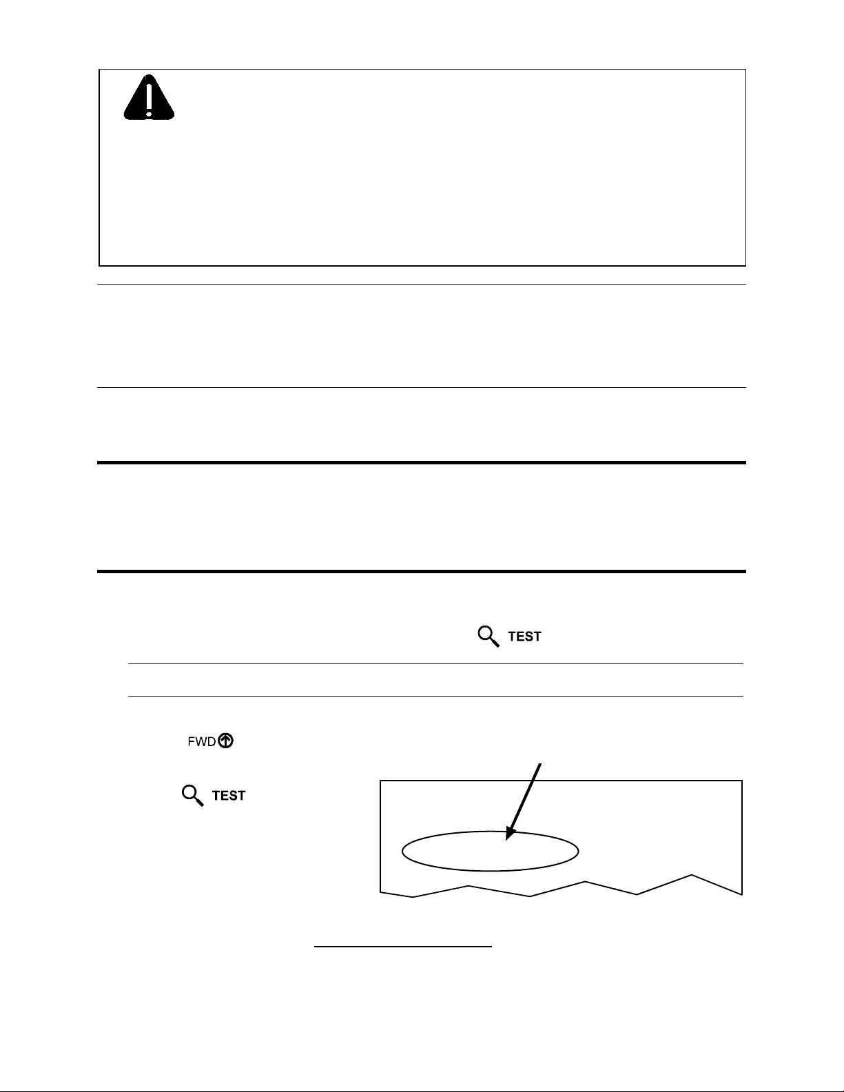
1. With media loaded and the printer powered ON, press the
Note: Use 2-inch (51 mm) or wider media with a Label Width setting that is matched to the label’s width;
see the Operator’s Manual for details.
2. Using the
Key, scroll to PRINT CONFIGURATION.
3. Press the
Key.
4. Examine the label for the Application
Version. Ensure that the Application
Version is 10.065, or greater.
CONFIGURATION
DATE NOT SET
PRINTER KEY:
4208-PA99-000412-488
APPLICATION VERSION:
83-2368-07ZN1 07.26 CP 09/19/2003
BOOT LOADER:
83-2268-02M 03.04 10/31/2000
5. If necessary, download the file ftp://ftp.datamax-oneil.com
Firmware” procedure in the Operator’s Manual.
then follow the “Updating Printer
Key.
SYSTEM SETTINGS
INTERNAL MODULE
1024
SCALABEL FONT CACHE
232
SYMBOL S ET
DATAMAX
ABSOLUTE COUNTE R S
0 inches
DATE NOT SET
RESETTABLE COUNTERS
1
Page 4
Installing the Option
If RFID is already installed, proceed to “Programming Information”; otherwise, follow the steps below:
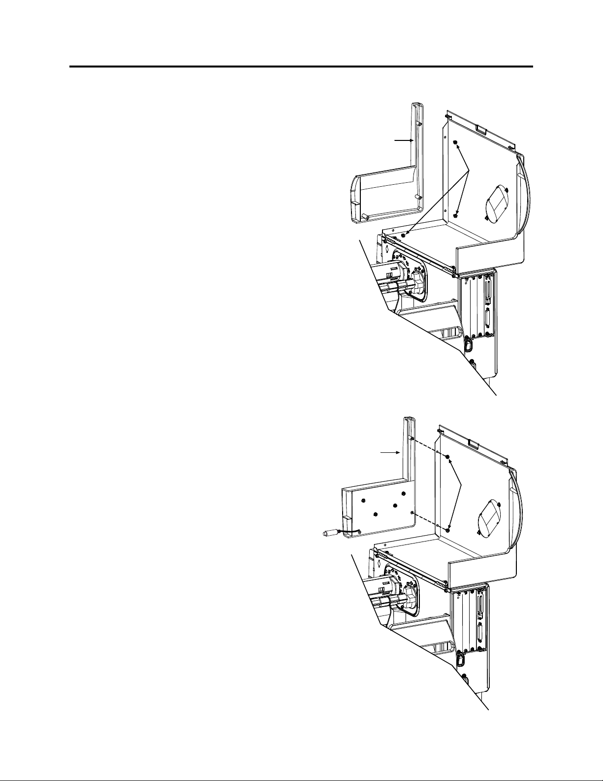
1. Turn off the power switch and unplug the printer.
2. Open the cover. Remove the three Screws that
secure the Front Cover Panel to the printer.
Front Cover
Panel
Screws
3. Position the RFID Front Cover Panel on the
printer and re-install two of the previously
removed screws, as shown.
RFID Front
Cover Panel
Screws
2
Page 5
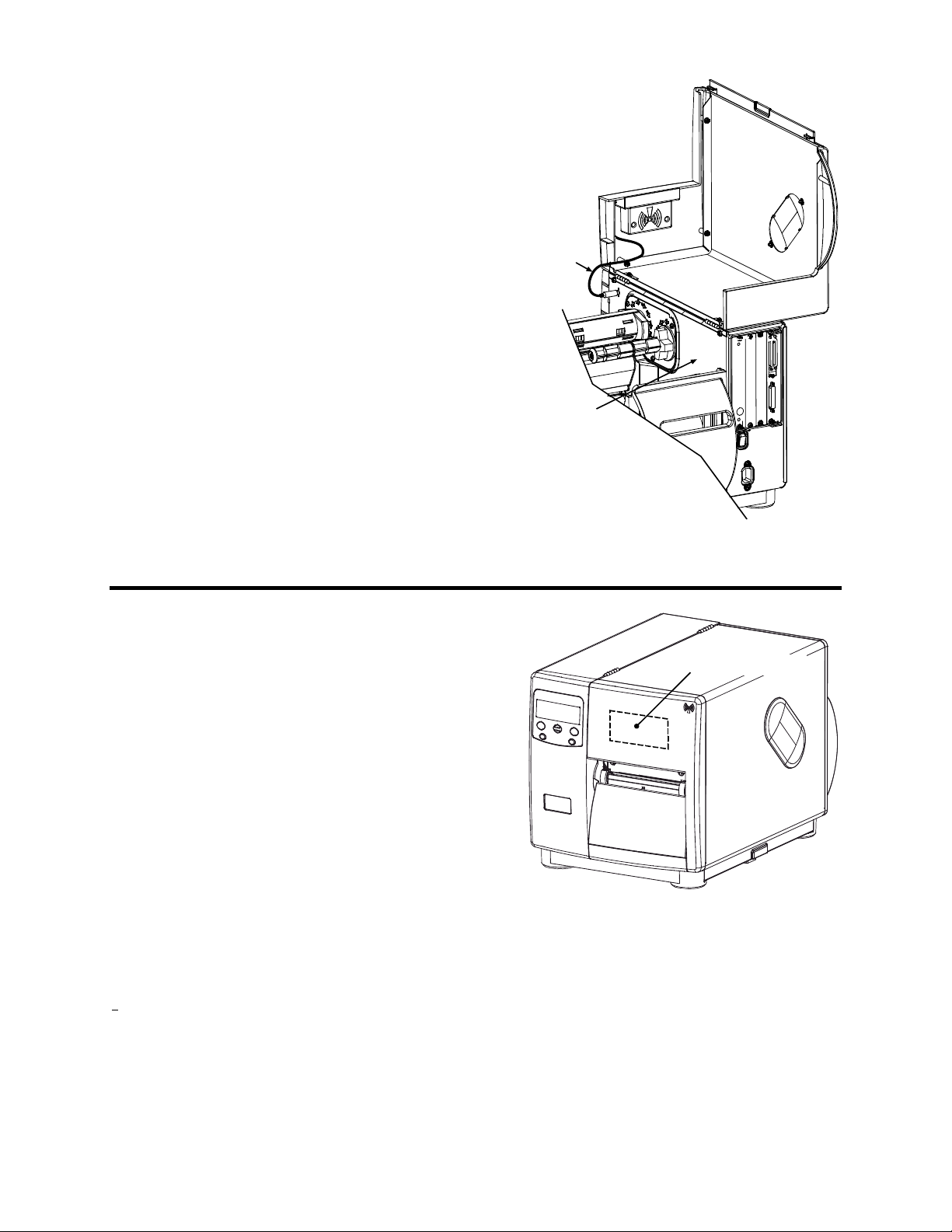
4. Route the RFID Cable, as shown, then connect
the cable to the connector in the Centerplate.
This completes the installation. Load Smart labels
and ribbon (if necessary) then close the printer’s
cover. Proceed to “Programming Information.”
RFID
Cable
Centerplate
Programming Information
Because the RFID device is attached to the cover, the
cover must be lowered for all printing applications.
Printer setup for the RFID media is also critical, so
the Present Distance and RFID position distance
should place the inlay directly under the upper tear
bar (near the antenna location). During operation,
RFID functions will be performed first and then the
printing functions will follow.
Ensure that the correct hardware has been enabled
(see below) so that the RFID module will initialize at
power up. There are three different modules:
Securakey HF (13.56 MHz) is capable of encoding data into standard ISO 15693 tags. These
typically have four bytes of data per block, with the number of blocks differing by manufacturer
(Texas Instrument contains 64 writable blocks; Philips contains 28 blocks; and, ST Micro LRI S12
contains 16 blocks. ST Micro LRI 64 tags are also supported.)
Alien UHF (915MHz) is capable of encoding data into 64 or 96-bit Class 1 EPC tags.
Samsys UHF (868 or 915 MHz) is multi-protocol. The protocols supported
*
are EPC Class 0, EPC
Class 0+ (Impinj or Matrics), EPC Class 1, EPC Class 1 Gen2, ISO 18000-6A, ISO 18000-6B
UCODE EPC 1.19 and EM4022/4222. Each offers different data sizes and other unique features.
* Not all protocols may be supported; see the firmware release notes for details.
^ ISO 18000-6B includes Intellitag® and UCODE non-EPC.
RFID
Module/Antenna
^
,
3
Page 6

Initialization
The initialization interface to the RFID module is auto baud detectable by the printer. Commands
necessary to enable, configure, read, write, and verify RFID tags are detailed below, arranged in the
following sections: Database / Menu, Data Input, Interfaces, Option Feedback, and Diagnostics.
Database / Menu
Menu mode accesses the following system level data (below, menu selections are listed on the left and
available parameters are listed on the right; see the Operator’s Manual for details):
PRINTER OPTIONS
RFID
MODE DISABLED, HF (Securakey), UHF CLASS 1 (Alien),
POSITION 0.00 - 4.00 (If 0.00 then the Print Position is used to
HF SETTINGS
TAG TYPE ISO 15693, TI, PHILIPS, ST LRI512, ST LRI64
AFI VALUE 2 Character Hex Value (Industry Codes)
AFI LOCK ENABLED or DISABLED
DFSID VALUE 2 Character Hex Value (Industry Codes)
DFSID LOCK ENABLED or DISABLED
EAS VALUE 2 Character Hex Value (Mfg. Codes)
AUDIO INDICATOR BUZZER ON or BUZZER OFF
ERASE ON FAULT ENABLED or DISABLED
UHF SETTINGS
TAG TYPE
TAG DATA SIZE
POWER ADJUST
EPC 0, EPC 0+ MATRICS, EPC 0+ IMPINJ, EPC 1,
64-BIT or 96-BIT (Samsys)
-4 dBm to +4 dBm (Samsys)
KILL CODE In the form: B3, B2, B1, B0
ACCESS CODE In the form: B3, B2, B1, B0
LOCK CODE
2 Character Hex Value (Alien)
LOCK AFTER WRITE ENABLED or DISABLED
RETRY ATTEMPTS 0 – 9
AUTO DETECT TAG Moves the label to find the tag and sets the present
COMMUNICATIONS / HOST SETTINGS
OPTION FEEDBACK DISABLED, SCANNER, RFID HEX, RFID ASCII
UHF MULTI-PROTOCOL (Samsys)
encode tag; otherwise, the Presented Position is used.)
UCODE EPC 1.19, EM 4022/4222, GEN 2 (Samsys)
distance. This will write to the tag in order to verify.
4
Page 7
Data Input
Data Input is in the form of System and Label Formatting commands, where <STX>KcRI and
<STX>KcQQQ support the entries that are shown in Menu mode. The RFID database file (RFID_DB)
resides on the Y module. It stores RFID information and should not be deleted. If not found at power-up
then factory defaults will be set. <STX>KcRIa configures the RFID interface, as noted below:
Value Units / Interpretation RFID Configuration Definition / Function
D = Disable Disables the RFID module. (“N” is also a valid disabler.)
Mn
AIhh
ALn
DIhh
DLn
Shh
Lhh
Rn
Wn
En
Pxxx
Tn where n:
Nn where n:
Un where n:
where n:
where hh: 2-Chararacter Hex ID Sets the Application Family Identifier (AFI), (HF only)
where n:
where hh: 2-Chararacter Hex ID Sets the Data Storage Format Identifier (DSFID), (HF only)
where n:
where hh: 2-Chararacter Hex ID
where hh: 2-Chararacter Hex ID Sets the Lock Code (Alien UHF only)
where n: 0 – 9 Sets the number of retries for RFID functions
where n:
where n:
where xxx: Is a 3-digit value
H = HF Enables the RFID module for HF (Securakey).
U = UHF Enables the RFID module for UHF Class 1 (Alien).
M = UHF Enables the RFID module for UHF Multi-Protocol (Samsys).
E = Enable,
D = Disable
E = Enable,
D = Disable
E = Enable,
D = Disable
E = Enable,
D = Disable
0 = ISO 15693
1 = Texas Instruments
2 = Philips
3 = ST Micro LRI 512
4 = ST Micro LRI 64
64 = 64-bit
96 = 96-bit
0 = EPC 0
1 = EPC 0+ Matrics
2 = EPC 0+ Impinj
3 = EPC 1
4 = ISO 18000-6A
5 = ISO 18000-6B
6 = UCODE EPC 1.19
7 = EM 4022/4222
8 = Gen 2
Allows locking the AFI after writing (HF only)
Allows locking the DSFID after writing (HF only)
Sets the Electronic Article Surveillance (EAS) set, representing
the manufacturer’s code. (HF only)
Allows locking the tag after writing.
Allows erasures of the tag on error (HF only)
Sets the tag encoding position: A value of 0.00 causes the print
position to be used; or, a value greater than 0 causes the
presented position to be used. (Subject to change.)
Establishes the tag type (HF only).
Sets the UHF tag data size (Samsys UHF only).
Sets the UHF tag type (Samsys UHF only).
Vn where n: Is a value from -4 to +4 Adjusts the power, in dBmn (Samsys UHF only).
5
Page 8

<STX>KcOFa configures the printer to output the status of the RFID operation, as noted below:
Value Range / Interpretation
D, Rx, S D - Disable
R - RFID Enable, where x = A - ASCII Response, x = H - Hexadecimal response
S - Scanner Enable
Interfaces
The printer has two methods of programming RFID tags: Direct Mode and Label Formatting Mode.
Direct Mode allows the Host to directly control RFID tag reading and writing, individually
processing each with status and data responses.
Label Formatting Mode utilizes the printer configuration to control RFID tag reading, writing,
and exception processing. The specification for the RFID operation is contained in the data fields
of a DPL label format and supports auto increment and decrement commands (+/-). Six RFID
operations are allowed per label.
The RFID programming data can be entered in one of two different formats: ASCII formats and
Hexadecimal formats:
The ASCII format is entered as you would normally see it (i.e., DATA).
The Hexadecimal format is entered as the hexadecimal equivalent of the ASCII data (i.e., DATA
becomes 44415441).
When entering the byte count, remember to consider the data format (from the examples, above, the
ASCII mode entry “DATA” has a byte count of four, while the hexadecimal mode entry “44415441” has
a byte count of eight).
Direct Mode - Generic Read/Write Interface
This interface allows the Host Application to send generic commands for RFID operations. These
commands consist of simple read and write operations requiring no knowledge (except data format)
of the tag types being used and utilize the printer’s database for specific parameters.
STX KaW Write Data to RFID Tag
This command instructs the RFID device to write data to the tag. It is expected that the tag
transponder will be within the read / write distance of the programming device; otherwise, a
warning will occur and a warning message (Read / Write Fail) will be displayed.
Syntax:
Where:
<STX>KaWAaaabbbcdee…e<CR>
Aaaa
- Optional – for data in the ASCII format, followed by the byte
count (000-999).
bbb
- HF – Starting block number (000 maximum block number).*
UHF – Should be 000.
6
Page 9

c
- Command 1. Reserved for Future (should be 0)
d
- Command 2. Reserved for Future (should be 0)
ee…e
- Data to be encoded on RFID tag (HF – the last used block will be
null-padded, if necessary).
Note: UHF ASCII formats must be 8 or 12 characters.
UHF Hexadecimal formats must be 16 or 24 character pairs.
Sample:
<STX>KaW0000054455354[CR]
The sample writes the data “TEST” at block zero.
* Dependent on transponder manufacturer.
STX KaR Read Data from RFID Tag
This command instructs the RFID device to read data from the tag and then place that data into a
replaceable field. It is expected that the tag transponder will be within the read / write distance of
the RFID programming device; otherwise, “Void” will be printed in the text or bar code label
field.
Syntax:
<STX>KaRAaaabbbcdee<CR>
Where:
A
- Optional – for data in the ASCII format.
aaa
- The number of bytes to read.
bbb
- HF - Starting block number (000 maximum block number).*
UHF – Should be 000.
Sample:
c
d
ee
<STX>L
1911A1802000010TEXT
U
X
<STX>KaR0000010001
<STX>G
- Command 1. Reserved. Should be 0.
- Command 2. Reserved. Should be 0.
- Field number in which to place the data (must be 01, 02, 03, etc.)
matching the order of Label Formatting command U.
Note: The 00 value will send read data to the host with no printing.
The sample creates a replaceable text field (01), recalls data from the RFID tag block zero (reading
only one block), and prints the data in the location specified by the replaceable field. Since there
are two digits per each hex value, replaceable fields should be twice as long than if using ASCII
data (e.g., the character “A” would be returned as “41”).
* Dependent on transponder manufacturer.
7
Page 10

h
Direct Mode - HF (13.56 MHz) ISO15693 Tag Interface
This interface allows the Host Application to perform specific operations pertaining to HF type tags.
These commands override the printer database as they interface directly to the tag module.
Knowledge of HF tags and their operation is required.
STX KtW Write Data to RFID Tag
This command instructs the RFID device to write data to the tag. It is expected that the tag
transponder will be within the read / write distance of the RFID programming device; otherwise,
a warning will occur and a warning message (Read / Write Fail) will be displayed.
Syntax:
<STX>KtWUn
1…n16Bncncnc
aaabcdee…e<CR>
Where:
Un
1…n16
- (Optional) Where n
is the Unique Identifier (UID) in
1…n16
exadecimal format. Must be sixteen characters long.
Bn
cncnc
- (Optional) Where n
is the data byte count, to allow non-
cncnc
printable characters (i.e., characters with hex values less than
0x20) to be encoded.
aaa
- Starting block number (000 maximum block number).*
b
- The number of retry attempts, 0-9.
c
- Lock block after writing:
0 = No Protection
1 = Write Protect
d
- Reserved. Should be 0.
ee…e
- Data to be encoded on RFID tag.
Sample 1:
<STX>KtWB004000900<0x00><0x01><0x02><0x03>[CR]
Sample 1 programs the hex values 0x00, 0x01, 0x02, 0x03 in block zero.
Sample 2:
<STX>KtWUE00700ABCDEF1234B004000510TEST[CR]
Sample 2 programs the data “TEST” to the tag with UID “E00700ABCDEF1234” at block zero
then write-protects block zero (attempting to write five additional times, if necessary). When write
protecting (locking) with UID, the separate lock command will also use the addressed mode and
the supplied UID.
* Dependent on transponder manufacturer.
Note: When using addressed commands and the tag with the specified UID cannot be found, a read /
write fault will be issued.
8
Page 11

h
STX KtR Read Data from RFID Tag
This command instructs the RFID device to read data from the tag and then put that data into a
replaceable field. It is expected that the tag transponder will be within the read / write distance of
the RFID programming device; otherwise, “Void” will be printed in the text or bar code label
field(s).
Syntax:
<STX>KtRUn
Haaabbbcdee<CR>
1…n16
Where:
Un
1…n16
- (Optional) Where n
is the Unique Identifier (UID) in
1…n16
exadecimal format. Must be sixteen characters long.
H
- (Optional) Hexadecimal data – An “H” may be added directly
after “R” to return a two character hex value of the data. Since
there are two digits per hex value, replaceable fields should be
twice as long than if using ASCII data (e.g., the character “A”
would be returned as “41”).
aaa
bbb
- Starting block number (000 maximum block number).*
- The number of blocks to read (001 maximum block
number).*
Sample:
c
d
ee
<STX>L
- The number of retry attempts, 0-9.
- Reserved. Should be 0.
- Field number in which to place the data (must be 01, 02, 03,
etc.) matching the order of Label Formatting command, U.
Note: The 00 value will send tag data to the host with no printing.
1911A1802000010TEXT
U
X
<STX>KtRUE00700ABCDEF1234H0000015001
<STX>G
The sample creates a replaceable text field (01), recalls data from the RFID tag block zero (reading
only one block, which is attempted nine times), and prints the data in the location specified by
replaceable field.
* Dependent on transponder manufacturer.
Note: When using addressed commands and the tag with the specified UID cannot be found, a standard
RFID read/write fault will be issued.
9
Page 12

STX KtU Read Unique Serial Number from RFID Tag
This command instructs the RFID device to read the unique serial number data from the tag and
then place that data into a replaceable field. It is expected that the tag transponder will be within
the read / write distance of the RFID programming device; otherwise, “Void” will be printed in
the text or bar code label field(s).
Note: This is a sixteen character alphanumeric value; therefore, the replaceable field must have an
adequate length.
Syntax:
<STX>KtUabcc<CR>
Where:
a
- The number of retry attempts, 0-9.
b
- Reserved. Should be 0.
cc
- Field number in which to place the data (must be 01, 02, 03, etc.)
matching the order of Label Formatting command, U.
Note: The 00 value will send the unique tag ID to the host with no
printing.
STX KtA Write Application Family Identifier (AFI) to Tag
This command writes the AFI data to the tag.
Syntax:
<STX>KtAabcc
Where:
a
- The number of retry attempts, 0-9.
b
- Lock the Application Family Identifier (AFI) after writing:
0 = No Protection
1 = Write Protect
cc
- Two character AFI value representing one byte.
Sample:
<STX>KtA91C3[CR]
The sample writes 0xC3 AFI byte, locking value, retrying nine times, if necessary.
10
Page 13

STX KtD Write Data Storage Format Identifier (DSFID) to Tag
This command writes the DSFID data to the tag.
Syntax:
<STX>KtDabcc
Where:
a
- The number of retry attempts, 0-9.
b
- Lock the Data Storage Format Identifier (DSFID) after writing:
0 = No Protection
1 = Write Protect
cc
- Two character DFSID value representing one byte.
Sample:
<STX>KtD91C3[CR]
The sample writes 0xC3 DSFID byte, locking value, retrying nine times, if necessary.
STX KtE Write Electronic Article Surveillance (EAS) Bit
This command writes the EAS bit for Philips ISO tags.
Syntax:
<STX>KtEabcc
Where:
a
- The number of retry attempts, 0-9.
b
- Electronic Article Surveillance (EAS) option:
0 = Set EAS
1 = Reset EAS
2 = Test EAS
cc
- Two character Manufacturer’s Code, representing one byte.
Sample:
<STX>KtE9004[CR]
The sample writes the EAS bit for Philips (0x04), retrying nine times, if necessary.
STX KtH Read and Feedback Tag Information to Host
This command returns the tag info to host.
Note: This command only works when the Data Flag for the tag is 0x0F (i.e., when the tag contains
DSFID, AFI, VICC and IC data.
Syntax:
Sample Feedback:
<STX>KtH
DATA FLAG: 0x0F
TAG ID: E004010000751412
DSFID: 0xE3
AFI: 0x01
NUM BLK: 0x1B
BLK SIZ: 0x03
IC REF: 0x01
11
Page 14

Direct Mode- UHF Interface
This interface allows the Host Application to perform specific operations pertaining to UHF type tags.
These commands override the printer database as they interface directly to the tag module.
Knowledge of UHF protocols and their operation is required.
STX KuW Write Data to RFID Tag
This command instructs the RFID device to write data to the tag. It is expected that the tag
transponder will be within the read / write distance of the RFID programming device; otherwise,
a warning will occur and a warning message (Read / Write Fail) will be displayed.
Syntax:
<STX>KuWabcc…c<CR>
Where:
a
- The number of attempts (1-9) to locate, erase, and program the
tag.
b
- Reserved. Should be 0.
Sample:
cc…c
<STX>KuW10ABCDEF0102030405[CR]
- Data to be encoded in the ASCII format. Must be sixteen
characters in length. The valid characters are 0-9, A-F.
Note: Must be 16 or 24 characters long.
The sample programs the data
<0xAB><0xCD><0xEF><0x01><0x02><0x03><0x04><0x05> to the tag, attempting to
write one additional time if necessary.
STX KuR Read Data from RFID Tag
This command instructs the RFID device to read data from the tag and then place that data into a
replaceable field. It is expected that the tag transponder is within the read / write distance of the
RFID programming device; otherwise, “Void” will be printed in the text or bar code label field(s).
Note: Data should be at least 16 or 24 characters in length.
Syntax:
<STX>KuRaa<CR>
Where:
Sample:
aa
<STX>L
- Field number in which to place the data (must be 01, 02, 03, etc.)
matching the order of Label Formatting command, U.
Note: The 00 value will send the unique tag ID to the host with no
printing.
D11
1911A1801000100 xxxxxxxxxxxxxxxx
U
1A31050002000200 xxxxxxxxxxxxxxxx
U
X
<STX>KuR01
<STX>Kur02
<STX>G
The sample creates a replaceable text field (01) and bar code field (02) and then recalls the data
from the tag and places it into the specified fields.
12
Page 15

STX KuE Erase RFID Tag (Alien only)
This command erases the tag by filling it with nulls (0x00).
Syntax:
Where:
STX KuL Lock RFID Tag (Alien only)
<STX>KuEa<CR>
a
- The number of attempts to locate and erase the tag, 1-9.
This command locks tag.
Syntax:
<STX>KuLabb<CR>
Where:
a
- The number of attempts to locate and lock the tag, 1-9.
bb
STX KuB Read Data from Gen2 Tag Section
- Two character Lock Code value, representing one byte.
This command reads a specific block address of a Gen2 tag.
Syntax:
<STX>KuBaaabbb
Where:
aaa
- Block address number, where: 000 is kill/access section; 001
is EPC section; 002 is Tag ID; and, 003 is user memory.
bbb
- Data offset in word length
Sample:
<STX>KuB001002
This example reads the block address 1 at offset word 2, which is location of the EPC data.
STX KuF Send RFID Device Firmware Version
This command instructs the RFID device to return the firmware version.
Syntax:
<STX>KuF<CR>
Printer response: DEVICE VERSION: XXX.XXX.XXX[CR]
13
Page 16

STX KuJ Write Data to Gen 2 Tag Section
This command writes a specific block address of a Gen2 tag.
Syntax:
Where:
Sample:
<STX>KuJaaabbb<data>
aaa
bbb
<data>
- Block address number, where: 000 is kill/access section; 001
is EPC section; 002 is Tag ID; or, 003 is user memory
- Data offset in word length
- Hexadecimal data, must be length of multiples of 4
<STX>KuJ001002112233445566778899AABBCC
This example writes data “112233445566778899AABBCC” to block address 1 at offset word 2,
which is the EPC data.
STX KuI Send Inventory (Alien only)
This command instructs the RFID device to read data from the tag and return it to the host. This is
a high level command that uses collision avoidance.
Note: CRC validation is performed, but the CRC is not included in the response (nor is the kill / lock
Syntax:
code).
<STX>KuI<CR>
Printer response: The data will be output as 16 hex bytes for a 64-bit tag, and 24 hex bytes for
a 96-bit tag.
STX KuG Send Tag ID with Global Scroll (Alien only)
This command instructs the RFID device to read data from the tag and return it to the host. The
reader sends GLOBALSCROLL air interface. Data is reported regardless of CRC verification.
Syntax:
<STX>KuG<CR>
Printer response:
Parameter 0 – Tag Decode Status:
0x00 = Good ID
0x01 = No Tag
0x02
= Collision
0x03 = CRC Error
Parameter 1 – Antenna Number: 0x00 (always)
Parameter 2 – Tag Data Length, with CRC and kill/lock codes.
0x0A = 64-Bit Tag
0x0E = 96-Bit Tag
Parameter 3: CRC byte one
Parameter 4: CRC byte two
Parameter 5 thru (Tag Data Length + 2): Tag Data, MSB to LSB
Note: Data response includes Parameters 2, 3, and 4 only with a ‘Good ID’ (Parameter 0) decode
status.
14
Page 17

STX KuT Send Tag ID (Alien only)
This command instructs the RFID device to read data from the tag and return it to the host. This is
a low level command that issues an air interface command to acquire one tag ID. There is no
collision avoidance used. A CRC validation is performed on the data; however, the CRC data is
not returned.
Syntax:
<STX>KuT<CR>
Printer response:
Parameter 0 – Tag Decode Status:
0x00 = Good ID
0x01 = No Tag
0x02
0x03 = CRC Error
Parameter 1 – Antenna Number: 0x00 (always)
Parameter 2 – Tag Data Length (only included if ‘Good’ ID status):
= Collision
0x08 = 64-Bit Tag
0x0C = 96-Bit Tag
Parameter 3 thru (Tag Data Length + 2), (only included if ‘Good’ ID status):
Tag Data, MSB to LSB.
STX KuV Send Tag ID with Verify (Alien only)
This command instructs the RFID device to send a VERIFY air interface command. Data is
reported regardless of CRC verification.
Syntax:
<STX>KuG<CR>
Printer response:
Parameter 0 – Tag Decode Status:
0x00 = Good ID
0x01 = No Tag
0x02
= Collision
0x03 = CRC Error
Parameter 1 – Antenna Number: 0x00 (always)
Parameter 2 – Tag Data Length, with CRC and kill/lock codes (only
included if ‘Good’ ID status):
0x0C = 64-Bit Tag
0x10 = 96-Bit Tag
Parameter 3: CRC byte one
Parameter 4: CRC byte two
Parameter 5 thru (Tag Data Length): Tag Data, MSB to LSB
Param Tag Data Length + 1: Kill Code
Param Tag Data Length + 2: Lock Code
15
Page 18

Label Formatting Mode
As mentioned earlier, Label Formatting mode utilizes the current printer configuration to process
each tag printed. (For exception processing and fault handling, see the
<STX>KcFH command.) The
specification for RFID programming is contained in the data fields of the DPL label format, as
described below.
Wx / W1x: RFID
Syntax for RFID (spaces shown for readability):
a bbb c d eee ffff gggg jj…j
Where:
Field Valid Inputs Meaning
Operation to perform, where:
a
1, 2, and 3
1 = Read (report to host)
2 = Write
3 = Write / Verify
bbb
c
d
eee
Wnx
0 Not Used
0 Not Used
xyy
RFID Hexadecimal Operation, where no ‘n’ is an implied 1.
Lock after write, where:
x = 0 – Use printer setup to determine if lock is performed.
x = 1 – Lock after write.
yy = Lock Code, representing a 2-character hex value (UHF
Alien only).
ffff
gggg
0000 – 9998 Starting block number to begin writing (HF only).
0000 Not Used
Valid
hexadecimal
jj…j
pairs per
character
followed by a
Data to write to the tag.
Note: UHF must be 16 or 24.
termination
character.
The following example encodes, starting at block 001, “Datamax writes RFID best”:
<STX>L
D11<CR>
2W1x0000000010000446174616D61782077726974657320524649442062657374<CR>
E
16
Page 19

WX / W1X: RFID with Byte Count Specifier
The upper case X identifies an RFID data string with a string 4-digit length specifier, which
allows values 0x00 through 0xFF to be included within the data strings without conflicting with
the DPL format record terminators. The four-digit decimal data byte count immediately follows
the four-digit column position field. This value includes all of the data following the byte count
field, but does not include itself.
Syntax for RFID with Byte Count Specifier (spaces shown for readability):
a bbb c d eee ffff gggg hhhh jj…j
Where:
Field Valid Inputs Meaning
Operation to perform, where:
a
1, 2, and 3
1 = Read (report to host)
2 = Write
3 = Write / Verify
bbb
c
d
eee
Wnx
0 Not Used
0 Not Used
xyy
RFID Hexadecimal Operation, where no ‘n’ is an implied 1.
Lock after write, where:
x = 0 – Use printer setup to determine if lock is performed.
x = 1 – Lock after write.
yy = Lock Code, representing a 2-character hex value (UHF
only).
ffff
gggg
hhhh
0000 – 9998 Starting block number to begin writing (HF only).
0000 Not Used
Four-digit
decimal data
byte count.
Number of bytes to follow (to include all bytes that follow until
the end of the data).
Note: UHF should be 8 or 12.
Valid ASCII
Data to write to the tag.
Note: UHF must be 8 or 12.
jj…j
character string
followed by a
termination
character.
The following example encodes, starting at block 001, “Datamax <CR> writes RFID best.” It
includes a Byte Count Specifier (the portion in bold), where 0024 equals a four-digit decimal data
byte count and includes all bytes that follow until the end of the data. Field termination is set by
the byte count.
<STX>L
D11<CR>
2W1X00000000100000024Datamax<CR>
writes RFID best<CR>
E
17
Page 20

Option Feedback
Once enabled, the printer will report information about the results of the last label printed. One
response per label is returned to the host (this includes each voided and retried label). The format and
contents of the returned information is as follows:
Printer response format:
<A;B;C;D;E;F>[CR]
A
Where:
- Device type:
R = RFID
S = Scanner
B
- Resulting status:
C = entire label complete
F = faulted (failed) label
U = unknown
C
- The number of expected reads for bar codes or tags, given in two
characters.
D
- The number of good reads for bar codes or tags, given in two
characters.
E
- The printer’s internal Job Identifier and Sub Job Identifier, given in
four characters each.
F
- The data read, delimited with semicolons (;) if multiple reads.
RFID response samples: Since RFID commands vary in operation, the data returned also differs.
Write commands return entire tag data; Write/Verify commands return the data written; and, Read
commands return data and length requested in the specified format. (See Appendix T for a listing of
commands.)
Write response example:
<R;C;00;00;0013:0001>[CR]
Write/Verify hexadecimal response example:
<R;C;01;01;0012:0001;446174616D61782077726974657320524649442062657374>[CR]
Read hexadecimal response example:
<R;C;01;01;0013:0001;446174616D61782077726974657320524649442062657374>[CR]
Write/Verify ASCII response example:
<R;C;01;01;0012:0001; Datamax writes RFID best >[CR]
Read ASCII response example:
<R;C;01;01;0013:0001; Datamax writes RFID best >[CR]
18
Page 21

Diagnostics
Menu mode accesses testing functions. Press the Menu Key and scroll to DIAGNOSTICS /
OPTIONS TESTING / TEST RFID.
Note: Upon selection, NOT INSTALLED will be displayed if the device is not equipped or communicating. In
this case, verify the Mode selection.
TAG DATA – Acts as an RFID reader and will read and display data from block zero through ten
for HF, or the entire tag for UHF. If the tag cannot be found after 10 tries, CANNOT READ
RFID TAG will be displayed.
DEVICE VERSION – Queries and displays the serial number of the RFID programming device
and the firmware version, useful for verifying device communications.
TAG ID – (HF only) Queries and displays the unique serial number for the tag.
19
Page 22

 Loading...