

Page 1
92-2324-01 Rev.D
Peel and Present Option
Page 2

Page 3
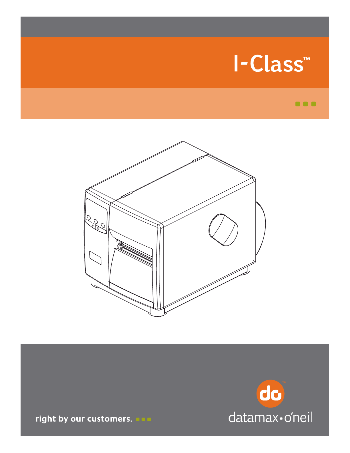
Contents of the Peel and Present Kit
This kit contains the following items:
Peel and Present Assembly
Platen Roller Assembly
Note: When using the Peel and Present Option do not exceed print or slew speeds
above 6 IPS.
Tools Required
The Peel and Present Option requires a #2 Flat and #2 Phillips screwdriver for installation.
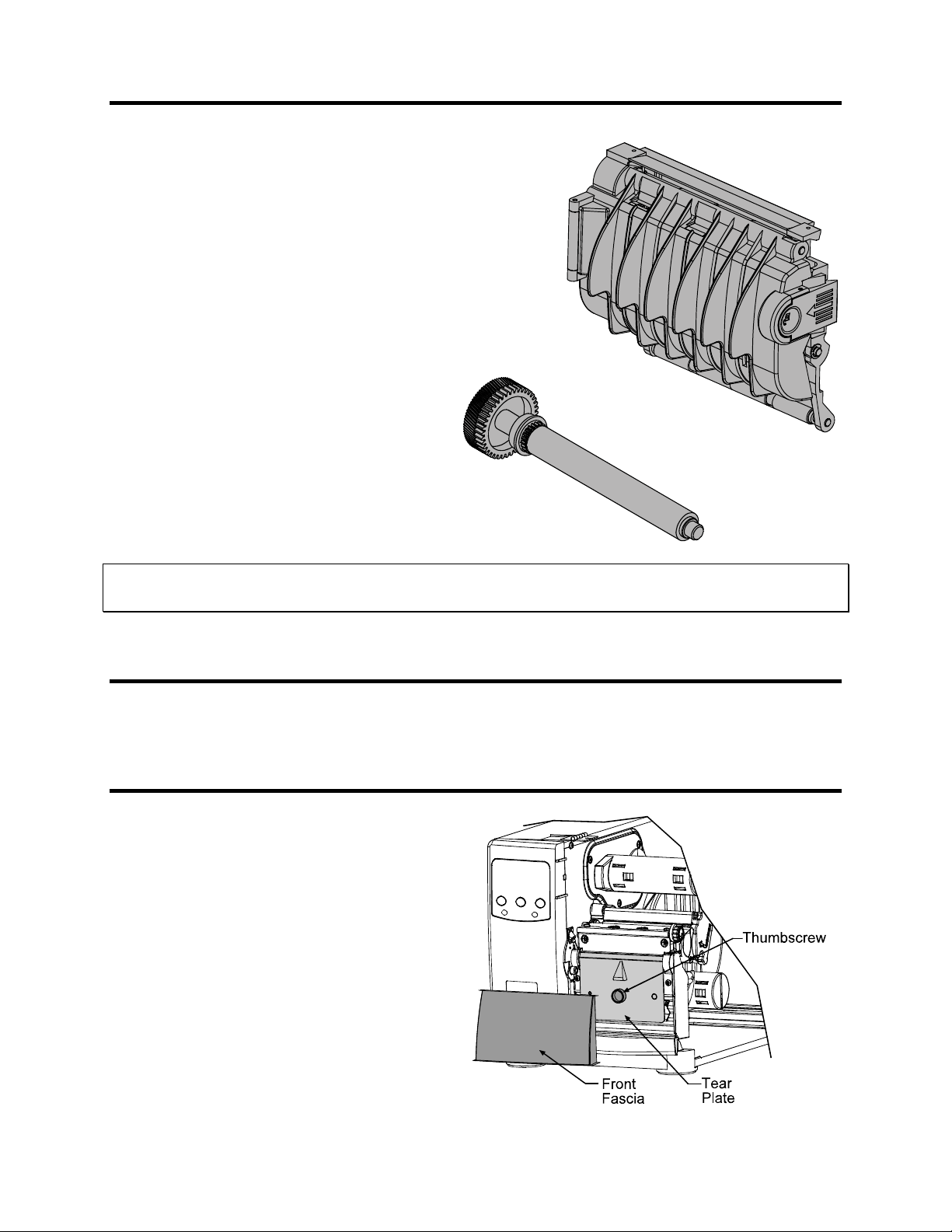
Preparing the Printer
Turn the power off and unplug the printer.
Remove any installed media from the printer.
Open the cover and remove the Front Fascia
by gently pulling it from the printer.
Loosen and remove the Thumbscrew and
then remove the Tear Plate
1
Page 4

Replacing the Platen Roller
Note:
Remove the Sensor Cover by pulling it from the
printer in the direction of the arrows, as shown.
(If equipped with the optional Present Sensor,
first disconnect the cabling to the Options
Connector).
Inspect your printer and determine if the Platen Roller Assembly installed in
your printer includes the Integral Gear as shown to the left. If the Integral
Gear is present it is not necessary to replace the Platen Roller Assembly,
proceed to ‘Installing the Peel and Present Assembly’
Integral
Gear
Note: If necessary, the Front Panel can be loosened to facilitate the removal of the Sensor Cover.
Remove the two Screws securing
the Bearing Plate then remove
the Bearing Plate.
Remove the Platen Roller
Assembly.
Reassembly
Place the Outside Bearing onto the Platen Roller Assembly.
Using care to avoid the Platen Roller, place a very small amount of silicon grease on the Compound
Gear.
Position the new Platen Roller Assembly in the printer.
Position the Bearing Plate onto the printer and secure with the two Screws.
Position the Sensor Cover. Then rotate the cover inward until it snaps into place.
Note: If necessary, the Front Panel can be loosened to facilitate the installation of the Sensor Cover.
2
Page 5

Installing the Peel and Present Assembly
Position the Peel and Present Assembly on
the front of the printer and then tighten the
mounting screw.
Mounting
Screw
Peel and Present
Assembly
Options
Connector
Route the Present Sensor Cable along the
Baseplate and on the inside of the Cable
Guide as shown. Plug the end into the
Options Connector as shown.
Cable
Guide
Baseplate
Present Sensor
Cable
3
Page 6

Setup and Configuration
The printer will automatically sense the presence of the Present Sensor and allow it to be enabled for
present printing. If you wish to enable the Present Sensor it must be enabled within the menu system. To
‘Enable’ or ‘Disable’ the Present Sensor follow the steps below.
Verify the printer is in the ‘Ready Mode’
Press the button. Using the
button scroll to ‘Printer Options’ and press the
button.
Using the button scroll to ‘Present Sensor’
and press the button.
Using the button scroll to either ‘Enable’ or
‘Disable. Press the button to select the
displayed setting, an asterisk will appear to the
left of the setting indicating that it is selected.
Once you have selected the desired setting
press the button repeatedly until the ‘Save
Changes’ message is displayed. Press the
button to save the changes or the button to
discard the changes.
Note: The use of the present sensor can also be controlled via software commands from the host.
Media Loading
Press in on the Peel Mechanism Latch and
allow the Peel Mechanism Front Cover to
swing open.
Load the printer with media, (see the
Operator’s Manual for more information).
Peel Mechanism
Latch
Peel Mechanism
Front Cover
4
Page 7

Peel off at least 20 inches of labels from the label backing. Route the label backing as shown below.
Route the Label Backing back to and around the Rewind Hub. Insert the edge of the Label Backing
into the Slot on the Rewind Hub. Then insert the Media Retainer, (supplied with the Rewind Option)
into the Slots on the Rewind Hub and rotate the Rewind Hub to remove any slack in the Label
Backing.
Label
Backing
Slots
Label
Backing
Rewind
Hub
Media
Retainer
Close the Peel Mechanism Front Cover. Press and hold the Feed button for three seconds, the printer
will then calibrate the media and normalize tracking. The printer should peel each label from its
backing as it prints.
5
Page 8

Periodic Maintenance
The Peel Mechanism Rollers will need to be disassembled and cleaned approximately every 100,000
inches to ensure trouble free operation. This cleaning interval may be more or less depending on the type
of adhesive on the back of your media. Heavy or “gummy” adhesive will require more frequent cleaning.
Upper Rollers:
Remove the Peel Mechanism from the printer.
Press in on the Latch and allow the Front Cover
to swing open.
Remove the small C-Clip from the Upper
Roller Shaft.
Remove Upper Roller Shaft and associated
Rollers. Note the order of the Rollers as they
are removed, they must be re-installed in the
same order.
Clean all
Roller Shaft. Isopropyl Alcohol can be used,
for heavy or stubborn deposits WD-40
adhesive remover can be used. Be sure all the
ridges on the rollers are free of debris.
Re-assemble the Upper Roller Shaft, Rollers,
and C-Clip into the Peel Mechanism Assembly.
surfaces of the Rollers and the Upper
or an
C-Clip
Latch
Upper Roller
Shaft
Front
Cover
Upper Roller
Shaft
Rollers
6
Page 9

Lower Rollers:
Remove the Peel Mechanism from the printer.
Press in on the Latch and allow the Front Cover
to swing open.
Push in on the Tab as shown, repeat for the
other side and then remove the entire Lower
Roller Assembly.
Remove Lower Roller Shaft and associated
Rollers. Note the order of the Rollers as they
are removed, they must be re-installed in the
same order.
Clean all
surfaces of the Rollers and the Lower
Roller Shaft. Isopropyl Alcohol can be used,
for heavy or stubborn deposits WD-40
or an
adhesive remover can be used. Be sure all the
ridges on the rollers are free of debris.
Re-assemble the Lower Roller Shaft and
Rollers. Reinstall the assembly into the Peel
Mechanism Assembly.
Push in on Tab
Lower Roller
Assembly
Lower Roller
Shaft
7
Page 10

 Loading...